EP2114338B1 - Kopfstützenanordnung - Google Patents
Kopfstützenanordnung Download PDFInfo
- Publication number
- EP2114338B1 EP2114338B1 EP08708133.7A EP08708133A EP2114338B1 EP 2114338 B1 EP2114338 B1 EP 2114338B1 EP 08708133 A EP08708133 A EP 08708133A EP 2114338 B1 EP2114338 B1 EP 2114338B1
- Authority
- EP
- European Patent Office
- Prior art keywords
- axis
- headrest
- arrangement according
- bearing
- around
- Prior art date
- Legal status (The legal status is an assumption and is not a legal conclusion. Google has not performed a legal analysis and makes no representation as to the accuracy of the status listed.)
- Not-in-force
Links
- 210000005069 ears Anatomy 0.000 claims description 2
- 230000000694 effects Effects 0.000 claims description 2
- 210000000078 claw Anatomy 0.000 description 25
- 238000010586 diagram Methods 0.000 description 13
- 0 CC(*)CC(CCN)(C*1)*2C3(C)C2*1(C1)C1C3 Chemical compound CC(*)CC(CCN)(C*1)*2C3(C)C2*1(C1)C1C3 0.000 description 1
- 230000006978 adaptation Effects 0.000 description 1
- 230000000712 assembly Effects 0.000 description 1
- 238000000429 assembly Methods 0.000 description 1
- 238000006073 displacement reaction Methods 0.000 description 1
- 230000002349 favourable effect Effects 0.000 description 1
- 230000004886 head movement Effects 0.000 description 1
- 230000001771 impaired effect Effects 0.000 description 1
- 230000007246 mechanism Effects 0.000 description 1
- 238000011144 upstream manufacturing Methods 0.000 description 1
Images





Classifications
-
- A—HUMAN NECESSITIES
- A61—MEDICAL OR VETERINARY SCIENCE; HYGIENE
- A61G—TRANSPORT, PERSONAL CONVEYANCES, OR ACCOMMODATION SPECIALLY ADAPTED FOR PATIENTS OR DISABLED PERSONS; OPERATING TABLES OR CHAIRS; CHAIRS FOR DENTISTRY; FUNERAL DEVICES
- A61G15/00—Operating chairs; Dental chairs; Accessories specially adapted therefor, e.g. work stands
- A61G15/10—Parts, details or accessories
- A61G15/12—Rests specially adapted therefor, e.g. for the head or feet
- A61G15/125—Head-rests
-
- A—HUMAN NECESSITIES
- A61—MEDICAL OR VETERINARY SCIENCE; HYGIENE
- A61G—TRANSPORT, PERSONAL CONVEYANCES, OR ACCOMMODATION SPECIALLY ADAPTED FOR PATIENTS OR DISABLED PERSONS; OPERATING TABLES OR CHAIRS; CHAIRS FOR DENTISTRY; FUNERAL DEVICES
- A61G13/00—Operating tables; Auxiliary appliances therefor
- A61G13/10—Parts, details or accessories
- A61G13/12—Rests specially adapted therefor; Arrangements of patient-supporting surfaces
- A61G13/1205—Rests specially adapted therefor; Arrangements of patient-supporting surfaces for specific parts of the body
- A61G13/121—Head or neck
Definitions
- the invention relates to a headrest assembly with a headrest for a medical chair.
- the head restraint assembly includes a head rest having a head rest surface disposed on a front side of the head rest and a bracket over which the head rest may be disposed on the treatment chair.
- the headrest assembly comprises a bearing arrangement arranged on the carrier with a first pivot bearing, via which the headrest is rotatably mounted relative to the carrier about at least one axis.
- headrest assemblies from the EP 0 701 806 A1 , of the DE-C-469 771 and the DE-B-12 27 189 known. In each of these documents is described that the headrest is mounted via a bearing assembly on a support of the backrest of the treatment chair.
- EP 0 701 806 A1 is the headrest via a ball joint in the center about all three spatial axes rotatable and pivotally mounted on a further substantially horizontally extending axis.
- DE-C-469 771 discloses a headrest which is pivotable about two parallel in a shell part and designed as a pivot joints hinge pin about two parallel and substantially horizontally extending axes.
- This headrest is also above this shell assembly about three hinges rotatable about an axis, these three axes are arranged at right angles to each other and intersect at a point.
- DE-B-12 27 189 describes a headrest which is pivotable about three parallel and substantially horizontal axes and about a respective axis arranged at right angles to the three axes.
- a headrest for an operating table which is rotatable by means of a pivotable mounting of the headrest about a substantially horizontally extending axes so that the pivot point is located at a distance in front of the support surface of the headrest.
- a headrest is known, which is attached via an arm to the backrest of a treatment chair, wherein the arm has two movable joints.
- FR 451582 A describes a headrest for a treatment chair, wherein by means of several pivotable bearings, the headrest is pivotable about different axes relative to the treatment chair.
- the object of the invention is to design and arrange a head restraint assembly such that the head restraint can be adjusted manually and at the same time precisely, but also quickly in defined steps and an optimal head movement of the standard patient is ensured during the adjustment.
- the axis X is arranged relative to the head support surface with a distance Ax in the region of the front in front of the head support surface.
- the precision and the rapid adjustability is achieved in that the adjusting device a first locking device and via the first latching device, a stepwise adjustment and fixation of the headrest at least about the axis X at intervals between 1 degree and 10 degrees, in particular between 2.5 degrees and 3.5 degrees can be achieved.
- the first locking device comprises a plurality of spaced apart locking elements and engaging in the locking elements claw, the locking elements medium or directly on the guideway or on the carriage and the claw middle or directly on the carriage or on the Guideway is arranged.
- the axis X runs approximately parallel to the cervical spine of a standard patient positionable with the head on the headrest.
- a rotation of the headrest is achieved about an axis with only one pivot bearing, which runs approximately coaxially to the spinal column of a standard patient, so that with the rotation of the headrest an ergonomic and thus optimal rotation of the standard patient head is effected.
- only one pivot bearing is used with a degree of freedom for rotation about the axis of rotation displaced before the headrest, it is possible to adjust the headrest quickly and accurately.
- the bearing arrangement can have at least one adjusting device for simple and rapid operation, by way of which the headrest can be released and fixed in a circumferential direction about at least one of the axes X, Y or Z.
- the distance Ax of the axis X can, for example, relative to the head support surface a dimension between 10 mm and 200 mm, in particular between 25 mm and 85 mm. Depending on the size of the standard patient different dimensions are favorable.
- the first pivot bearing about the axis X for example, have a radius Rx between 25 mm and 200 mm, in particular between 105 mm and 110 mm and greater than the distance of the axis X. In certain areas, a shape design of the housing and the headrest is possible when an upstream axis X is realized.
- the bearing arrangement comprises a second pivot bearing, via which the headrest is rotatably mounted relative to the support about an axis Y, wherein the axis Y intersects the axis X at an intersection Pyx and at an angle Wxy the axis X is arranged, the point Pyx is arranged relative to the head support surface with the distance Ax in front of the front of the headrest and the distance Ax relative to the head support surface has a dimension between 10 mm and 200 mm, in particular between 25 mm and 85 mm and wherein the axis Y is approximately parallel to a line leading from the upper cervical vertebra through the nasal tip with respect to a standard patient positionable with the head on the headrest.
- the headrest via the bearing assembly is pivotable relative to the support at least about an axis Z, wherein the axis Z intersects the axis Y and is arranged at an angle Wyz to the axis Y and wherein the axis Z with respect to a the head on the headrest positionable norm patient runs approximately parallel to a line connecting both ears.
- the kinematics can be extended, for example, by the angle Wxy and / or the angle Wyz having a dimension between 0 degrees and 90 degrees.
- the first pivot bearing for the pivotable mounting of the headrest about the axis X is formed at least in two parts with a curved or circular guideway and a slide slidably mounted on the guide track.
- the guideway is secured relative to the carriage at least in a direction of the axis Y against displacement via a stop.
- the guideway or the carriage may be arranged on the headrest or on the carrier.
- the second pivot bearing for the pivotal mounting of the headrest about the axis Y on the guide track or on the carriage is arranged and has a coaxial or parallel to the axis Y arranged pin and a rotatably mounted on the pin receptacle.
- the headrest on its front side has a limited by the head rest surface head rest and an at least indirectly adjacent to the head rest housing, wherein the housing is arranged with respect to the head rest opposite the head rest surface on a rear side of the headrest and wherein the head restraint is mounted on the housing or a connecting element on the bearing assembly.
- the claw can be mounted pivotably about the axis Z on the receptacle.
- the adjusting device has a second locking device and the second locking device stepwise adjustment and fixation of the headrest at least about the axis Y at intervals between 1 degree and 10 degrees, in particular between 2.5 degrees and 3, 5 degrees is achievable.
- the second latching device has a plurality of spaced-apart holding elements and an engaging in the holding elements anchor, the holding elements medium or directly on the guideway or on the carriage and the armature middle or arranged directly on the recording is.
- the armature and / or the claw are mounted pivotably about the axis Z on the receptacle and that the claw and / or the armature in the circumferential direction about the axis Z by means of a receiving element arranged on the spring element in the same direction or biased in opposite directions.
- the spring element may be formed as a spiral spring, be arranged coaxially to the axis Z on the receptacle and abut in the circumferential direction about the axis Z on the jaw and / or on the anchor.
- the adjusting device has at least one operating element for opening and closing the claw and / or the armature associated with the first locking device and / or the second locking device.
- the operating element has at least one first operating lever and the first operating lever about a pivot axis arranged at right angles to the axis Y. is pivotally mounted on the inside of the housing on the housing, that the housing has at least a first recess in which a handle part is arranged and that the operating lever has a relation to the pivot axis opposite to the handle part arranged head part and the handle part manually about the pivot axis pivotable and can be applied to the claw and / or to the anchor.
- the claw and / or the armature can also be pivotable about the head Y in the circumferential direction about the axis Y.
- the operating element has a second operating lever with a handle part and a head part, which is mounted on the housing to pivot about a second pivot axis and about the claw and / or the armature in the same effect as with the first operating lever about the axis Z can be pivoted.
- the redundancy is increased by the fact that the first pivot bearing and the second pivot bearing are arranged in the direction of the axis Z between the two control levers and the claw and / or the armature can be pivoted redundantly via the two control levers.
- the bearing arrangement has a third pivot bearing for the pivotable mounting of the headrest about the axis Z, wherein the third pivot bearing is formed as a sliding bearing and disposed between the carrier and the first pivot bearing.
- the headrest can be stored in an ergonomic respect its pivotal range about the axis X in an angular range Wx between 20 degrees and 100 degrees, in particular between 46 degrees and 50 degrees about the axis X pivotable about the bearing assembly.
- the headrest for example, in its pivoting range about the axis Y in an angular range Wy between 15 degrees and 80 degrees, in particular between 34 degrees and 38 degrees about the axis Y are pivotally mounted on the bearing assembly.
- a dental treatment unit which has an instrument unit 6 and a treatment chair 2 and provided on the treatment chair 2 head restraint assembly 1.
- the instrument unit 6 consists of a tray 60, which is held by a support arm 601.
- the tray 60 serves as a shelf for treatment cutlery, treatment material and also for receiving dental hand instruments 61, 61 '.
- the hand instruments 61, 61 ' are supplied via electrical, pneumatic or hydraulic lines 602.
- a lamp 62 is assigned to the treatment chair 2 immediately adjacent to a monitor 63.
- the treatment chair 2 has a backrest 20 and a seat part 21, which is mounted on a foot 23 via a height adjustment 24.
- a footrest 22 is arranged on the seat part 21.
- the treatment chair 2, the shelf 60, the monitor 63 and the lamp 62 are controllable via a foot pedal 64, to which they are connected via supply and data lines 65.
- the principles of operation of the bearing assembly 4 are in the Fig. 2 to 6 shown in more detail and described below.
- the headrest 5 has as in FIGS. 13 and 14 represented on its rear side 54, a housing 51 and on its front 53 a head rest 52 with a head rest surface 50 on.
- the bearing assembly 4 is partially disposed below the housing 51 and partially under a cover 31 of the carrier 3 and in the Fig. 9 to 12 shown in more detail.
- the bearing assembly 4 is designed with respect to three spatial axes X, Y and Z, which are each arranged at right angles to each other in these embodiments. A non-rectangular arrangement is provided in an embodiment not shown.
- the axis X extends substantially in the vertical direction parallel to the head support surface 50.
- the axis Y extends substantially in the horizontal direction at right angles to the head support surface 50 and intersects the axis X.
- the axis Z also extends substantially in the horizontal direction and at right angles to the axis Y. Furthermore, the axis Z intersects the axis Y behind the head support surface 50 in the region of the carrier 3.
- the rotation about the axis X corresponds to the rotation of the head of a standard patient to the left and to the right when the axis X passes through the upper cervical vertebra.
- the rotation about the axis Y corresponds to the lateral tilting of the head of the standard patient towards the shoulders.
- Fig. 2 includes the axis X arranged at right angles to the axis Y with this an angle Wxy of 90 degrees and extends in the upright position of the backrest 20 substantially vertically.
- the axis X is arranged according to the invention with a distance Ax to the headrest 5 or to the head support surface 50.
- Fig. 3a and 3b clarify the headrest 5 is moved relative to the carrier 3 on a circular path.
- the circular path has a radius Rx whose center is the axis X.
- the headrest 5 pivots approximately at a point which lies in the region of the vertebral column or cervical vertebra of a standard patient who is placed on the treatment chair 2 and applies his back of the head to the headrest surface 50. This ensures that the natural rotational movement of the standard patient can be modeled ergonomically precise.
- Fig. 3a the headrest 5 is shown in relation to the pivoting about the axis X in a zero position.
- Fig. 3b the headrest 5 is pivoted about an angular range Wx about the axis X.
- the axis Y passes through the headrest 5 in a substantially horizontal direction.
- the inventive storage of the headrest 5 allows as in Fig. 4a and 4b at the same time as rotation about the axis X, also rotate about the axis Y.
- Fig. 4a the headrest 5 is shown in a zero position with respect to the rear side 54 with respect to the rotation about the axis Y.
- Fig. 4b the headrest 5 is shown rotated by an angular range Wy in a clockwise direction relative to the zero position.
- a rotation of the headrest 5 about the axis Z is in the schematic diagram according to Fig. 2 intended.
- a storage of the headrest 5 about the axis Z is not provided.
- Fig. 5 shows a schematic diagram of the bearing assembly 4 of the headrest 5 about the axis X and about the axis Y.
- the bearing arrangement 4 has a first pivot bearing 41 with a guideway 410 and a slide 411.
- the guideway 410 is as in FIG Fig. 9 and 10 shown in detail on the carrier 3 stored.
- On this concentric with the axis X arranged guide track 410 of the carriage 411 is slidably mounted, so that the carriage 411 also moves in a part-circular path about the axis X.
- the carriage 411 is attached indirectly via a second pivot bearing 42 on the housing 51, so that with the carriage 411, the entire headrest 5 with the head rest 52 on the carriage 411 is partially circular about the axis X movable.
- the second pivot bearing 42 with which the headrest 5 is rotatable about the axis Y, has a pin 420 and a receptacle 421 rotatably mounted on the pin 420.
- the pin 420 is mounted directly on the carriage 411.
- the housing 51 On the receptacle 421, the housing 51 is fixed.
- the housing 51 can be rotated about the receptacle 421 about the axis Y and simultaneously about the carriage 411 about the axis X.
- the pin 420 and thus the axis Y pivot with the carriage 411 about the axis X.
- the angular range Wy is limited to ⁇ 18 degrees in this embodiment.
- the pivot radius Rx corresponds to the distance between the axis X and the guide track 410 of the carriage 411 and is 107.5 mm in this embodiment.
- the distance Ax between the head support surface 50 and the axis X corresponds due to the structure of the headrest 5 a fraction of the radius Rx.
- the movement of the headrest 5 about the axis X and about the axis Y is controlled by an adjusting device 40, which allows a screened adjustment in steps of about 3 degrees.
- a first latching device 45 is provided, which regulates the adjustment about the axis X, and a second latching device 46, which regulates the adjustment about the axis Y.
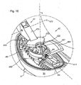
- the first latching device 45 has as in Fig. 9 and 10 shown in detail a plurality of locking elements 450, which are arranged directly on the guide track 410.
- this locking elements 450 engages a claw 451, which is pivotally mounted on the carriage 411.
- the claw 451 is mounted from a position engaging in the latching elements 450 in a position releasing the latching elements 450 about the axis Z on the receptacle 421.
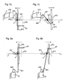
- Fig. 7a and 7b the mode of operation is shown in principle.
- the locking elements 450 are statically supported on the carrier 3 via the guide track 410.
- the claw 451 pivots from the free or open position according to FIG Fig. 7a counterclockwise in a latched or closed position according to Fig. 7b ,
- the claw 451 is biased by a spring element 43 in the circumferential direction about the axis Z counterclockwise, so that the spring element 43rd in the open position of the claw 451 exerts more force than in the closed position.
- the closed position is the decisive factor for the security against a loosening of the headrest 5.
- the second locking device 46 has as in Fig. 9 and 10 shown in detail a plurality of holding elements 460, which are arranged directly on the inside of the housing 51. In these holding elements 460 engages an armature 461, which is pivotally mounted on the receptacle 421.
- the armature 461 is mounted on the receptacle 421 about the axis Z from a position latching into the retaining elements 460 into a position releasing the retaining elements 460.
- Fig. 8a and 8b show the operation in principle.
- the holding elements 460 are arranged on the housing 51, which moves with the carriage 411 about the axis X.
- the armature 461 pivots from the open position according to FIG Fig. 8a in a clockwise direction in a closed position according to Fig. 8b ,
- the armature 461 is biased by the spring element 43 in the circumferential direction about the axis Z in a clockwise direction, so that the armature strives 461 by the spring element 43, the closed position, which in turn is crucial for the safety of the locking.
- Fig. 6 illustrates in two-dimensional view the above-described kinematic conditions.
- the pin 420 rotates in a part-circular path about the axis X of radius Rx.
- the claw 451 and the armature 461 are rotatably mounted about the axis Z.
- the claw 451 engages in the locking elements 450 and the armature 461 in the holding elements 460 on the housing 51st
- the claw 451 and the armature 461 are used to adjust the headrest 5 about the axis X and simultaneously about the axis Y. as in Fig. 9 to 12 shown pressed against an operating element 47 against its spring bias in the open position.
- the spring element 43 is formed as a spiral spring, mounted on a bolt 44 coaxial with the axis of rotation of the claw 451 and coaxial with the axis of rotation of the armature 461 and biased against these two components.
- the operating element 47 has a first operating lever 470 mounted in the housing 51 about a first pivot axis 472.
- the operating lever 470 is manually pivotable about the first pivot axis 472 via a grip part 471 and rests on the claw 451 and on the armature 461 with a head part 473 arranged with respect to the pivot axis 472 opposite the grip part 471.
- the operating lever 470 is thus biased by the spring element 43 indirectly via the claw 451 and the armature 461.
- the grip 471 is as in FIG Fig. 11 and 13 shown disposed in a first recess 510 in the housing 51 and can be pressed manually from the back 54 in the direction of the interior of the housing 51.
- the head part 473 is moved depending on the length ratios of the operating lever 470 with respect to the first pivot axis 472 in the direction of the axis Y on the receptacle 421, resulting in an opening of the latching by the pivoting of the claw 451 and the armature 461.
- the adjusting device 40 can, as in Fig. 11 to 13 represented redundantly via a second operating lever 474 are operated.
- the second operating lever 474 is formed similar to the first operating lever 470 and disposed opposite to the receptacle 421 opposite in the housing 51.
- the second operating lever 474 is about a parallel to the first pivot axis 472 also with respect to the receptacle 421 oppositely disposed second pivot axis 475th pivoted.
- a gripping part 471 ' is arranged in a second recess 511 lying opposite the carrier 3 of the first recess 510.
- a head portion 473 'of the second operating lever 474 also rests on the claw 451 and the armature 461.
- the Wirkurigskos the two operating lever 470, 474 is the same.
- the headrest 5 can be redundantly adjusted on both sides of the back 54 and solve and set.
Landscapes
- Health & Medical Sciences (AREA)
- Oral & Maxillofacial Surgery (AREA)
- Life Sciences & Earth Sciences (AREA)
- Animal Behavior & Ethology (AREA)
- General Health & Medical Sciences (AREA)
- Public Health (AREA)
- Veterinary Medicine (AREA)
- Accommodation For Nursing Or Treatment Tables (AREA)
Description
- Die Erfindung betrifft eine Kopfstützenanordnung mit einer Kopfstütze für einen medizinischen Behandlungsstuhl. Die Kopfstützenanordnung umfasst eine an einer Vorderseite der Kopfstütze angeordnete Kopfauflage mit einer Kopfauflagefläche und einen Träger, über den die Kopfstütze an dem Behandlungsstuhl angeordnet werden kann. Ferner umfasst die Kopfstützenanordnung eine am Träger angeordnete Lageranordnung mit einem ersten Drehlager, über das die Kopfstütze relativ zum Träger um zumindest eine Achse drehbar gelagert ist.
- Es sind Kopfstützenanordnungen aus der
EP 0 701 806 A1 , derDE-C-469 771 und derDE-B-12 27 189 bekannt. In jeder dieser Druckschriften ist beschrieben, dass die Kopfstütze über eine Lageranordnung an einem Träger der Rückenlehne des Behandlungsstuhls gelagert ist. - Gemäß der
EP 0 701 806 A1 ist die Kopfstütze über ein Kugelgelenk in dessen Mittelpunkt um alle drei Raumachsen drehbar und über eine weitere im Wesentlichen horizontal verlaufende Achse schwenkbar gelagert. - In der
DE-C-469 771 ist eine Kopfstütze offenbart, die über zwei in einem Schalenteil gemeinsam klemmbare und als Drehgelenke ausgebildete Gelenkbolzen um zwei parallele und im Wesentlichen horizontal verlaufende Achsen schwenkbar ist. Diese Kopfstütze ist ferner oberhalb dieser Schalenanordnung über drei Drehgelenke um jeweils eine Achse drehbar, wobei diese drei Achsen rechtwinklig zueinander angeordnet sind und sich in einem Punkt schneiden. - In der
DE-B-12 27 189 wird eine Kopfstütze beschrieben, die um drei parallele und im Wesentlichen horizontal verlaufende Achsen sowie um jeweils eine zu den drei Achsen rechtwinklig angeordnete Achse schwenkbar ist. - In der
DE 91 16 002 U1 ist eine Kopfstütze für einen Operationstisch bekannt, die mittels einer schwenkbaren Lagerung der Kopfauflage um eine im wesentlichen horizontal verlaufende Achsen so drehbar ist, dass sich der Drehpunkt in einem Abstand vor der Auflagefläche der Kopfstütze befindet. - Aus der
US 3,761,128 ist eine Kopfstütze bekannt, die über einen Arm an der Rückenlehne eines Behandlungsstuhls befestigt ist, wobei der Arm zwei bewegliche Gelenke aufweist. - In der
FR 451582 A - Die Aufgabe der Erfindung besteht darin, eine Kopfstützenanordnung derart auszubilden und anzuordnen, dass die Kopfstütze manuell und gleichzeitig präzise, aber auch schnell in festgelegten Schritten verstellt werden kann und bei der Verstellung eine optimale Kopfbewegung des Normpatienten gewährleistet ist.
- Gemäß der Erfindung Laut Anspruch 1 die Achse X relativ zu der Kopfauflagefläche mit einem Abstand Ax im Bereich der Vorderseite vor der Kopfauflagefläche angeordnet.
- Die Präzision und die schnelle Verstellbarkeit wird dadurch erreicht, dass die Verstelleinrichtung eine erste Rastvorrichtung aufweist und über die erste Rastvorrichtung eine schrittweise Verstellung und Fixierung der Kopfstütze zumindest um die Achse X in Abständen zwischen 1 Grad und 10 Grad, insbesondere zwischen 2,5 Grad und 3,5 Grad erreichbar ist.
- Hierzu ist vorgesehen, dass die erste Rastvorrichtung mehrere mit Abstand zueinander angeordnete Rastelemente und eine in die Rastelemente eingreifende Klaue aufweist, wobei die Rastelemente mittel- oder unmittelbar an der Führungsbahn oder an dem Schlitten und die Klaue mittel- oder unmittelbar an dem Schlitten oder an der Führungsbahn angeordnet ist.
- Die Achse X verläuft hierbei in etwa parallel zu der Halswirbelsäule eines mit dem Kopf auf der Kopfstütze positionierbaren Normpatienten.
- Durch den Abstand Ax der Achse X wird mit nur einem Drehlager eine Drehbarkeit der Kopfstütze um eine Achse erreicht, die in etwa koaxial zu der Wirbelsäule eines Normpatienten verläuft, sodass mit der Drehung der Kopfstütze eine ergonomische und somit optimale Drehung des Normpatientenkopfes bewirkt wird. Dadurch, dass nur ein Drehlager mit einem Freiheitsgrad für die Drehung um die vor die Kopfstütze verlagerte Drehachse eingesetzt wird, ist es möglich, die Kopfstütze schnell und präzise einzustellen.
- Die Lageranordnung kann für eine einfache und schnelle Bedienbarkeit zumindest eine Verstelleinrichtung aufweisen, über die die Kopfstütze in eine Umfangsrichtung um zumindest eine der Achsen X, Y oder Z lösbar und fixierbar ist.
- Der Abstand Ax der Achse X kann beispielsweise relativ zu der Kopfauflagefläche ein Maß zwischen 10 mm und 200 mm, insbesondere zwischen 25 mm und 85 mm aufweisen. Je nach Größe des Normpatienten sind verschiedene Maße günstig.
- Das erste Drehlager um die Achse X kann beispielsweise einen Radius Rx zwischen 25 mm und 200 mm, insbesondere zwischen 105 mm und 110 mm und größer als der Abstand der Achse X aufweisen. In gewissen Bereichen ist eine Formgestaltung des Gehäuses und der Kopfauflage möglich, wenn eine vorgelagerte Achse X realisiert wird.
- Für eine erweiterte ergonomische Anpassung ist es vorteilhaft, dass die Lageranordnung ein zweites Drehlager aufweist, über das die Kopfstütze relativ zum Träger um eine Achse Y drehbar gelagert ist, wobei die Achse Y die Achse X in einem Schnittpunkt Pyx schneidet und in einem Winkel Wxy zu der Achse X angeordnet ist, der Punkt Pyx relativ zu der Kopfauflagefläche mit dem Abstand Ax vor der Vorderseite der Kopfstütze angeordnet ist und der Abstand Ax relativ zu der Kopfauflagefläche ein Maß zwischen 10 mm und 200 mm, insbesondere zwischen 25. mm und 85 mm aufweist und wobei die Achse Y in Bezug zu einem mit dem Kopf auf der Kopfstütze positionierbaren Normpatienten in etwa parallel zu einer Linie verläuft, die vom oberen Halswirbel durch die Nasenspitze führt.
- Dadurch, dass die Achse Y die Achse X im Bereich des Halswirbels schneidet, wird die vorteilhafte Ergonomie nicht beeinträchtigt, sondern weiter gesteigert, da der Normpatientenkopf auch bezüglich der Achse Y präzise geführt wird.
- Zudem ist vorgesehen, dass die Kopfstütze über die Lageranordnung relativ zum Träger zumindest um eine Achse Z schwenkbar ist, wobei die Achse Z die Achse Y schneidet und in einem Winkel Wyz zu der Achse Y angeordnet ist und wobei die Achse Z in Bezug zu einem mit dem Kopf auf der Kopfstütze positionierbaren Normpatienten in etwa parallel zu einer Linie verläuft, die beide Ohren verbindet.
- Die Kinematik kann beispielsweise dadurch erweitert werden, dass der Winkel Wxy und/oder der Winkel Wyz ein Maß zwischen 0 Grad und 90 Grad aufweist.
- Es ist vorgesehen, dass das erste Drehlager für die schwenkbare Lagerung der Kopfstütze um die Achse X zumindest zweiteilig mit einer bogen- oder kreisförmigen Führungsbahn und einem auf der Führungsbahn verschiebbar gelagerten Schlitten ausgebildet ist.
- Hierzu ist es vorteilhaft, dass die Führungsbahn gegenüber dem Schlitten zumindest in eine Richtung der Achse Y gegen eine Verschiebung über einen Anschlag gesichert ist.
- Die Führungsbahn oder der Schlitten können an der Kopfstütze oder an dem Träger angeordnet sein.
- Ferner ist vorgesehen, dass das zweite Drehlager für die schwenkbare Lagerung der Kopfstütze um die Achse Y auf der Führungsbahn oder auf dem Schlitten angeordnet ist und einen koaxial oder parallel zur Achse Y angeordneten Zapfen sowie eine auf dem Zapfen drehbar gelagerte Aufnahme aufweist.
- Eine vorteilhafte Ausbildung ist, dass die Kopfstütze auf ihrer Vorderseite eine durch die Kopfauflagefläche begrenzte Kopfauflage und ein zumindest mittelbar an die Kopfauflage angrenzendes Gehäuse aufweist, wobei das Gehäuse in Bezug auf die Kopfauflage gegenüberliegend der Kopfauflagefläche auf einer Rückseite der Kopfstütze angeordnet ist und wobei die Kopfstütze über das Gehäuse oder ein Verbindungselement an der Lageranordnung gelagert ist.
- Die Klaue kann um die Achse Z schwenkbar an der Aufnahme gelagert sein.
- Hinsichtlich der Steigerung der Ergonomie ist vorgesehen, dass die Verstelleinrichtung eine zweite Rastvorrichtung aufweist und über die zweite Rastvorrichtung eine schrittweise Verstellung und Fixierung der Kopfstütze zumindest um die Achse Y in Abständen zwischen 1 Grad und 10 Grad, insbesondere zwischen 2,5 Grad und 3,5 Grad erreichbar ist.
- Für die Verrastung ist vorgesehen, dass die zweite Rastvorrichtung mehrere mit Abstand zueinander angeordnete Halteelemente und einen in die Halteelemente eingreifenden Anker aufweist, wobei die Halteelemente mittel- oder unmittelbar an der Führungsbahn oder an dem Schlitten und der Anker mittel- oder unmittelbar an der Aufnahme angeordnet ist.
- Besonders vorteilhaft ist es, dass der Anker und/oder die Klaue um die Achse Z schwenkbar an der Aufnahme gelagert sind und dass die Klaue und/oder der Anker in Umfangsrichtung um die Achse Z mit Hilfe eines an der Aufnahme angeordneten Federelements in die gleiche Richtung oder in entgegengesetzte Richtungen vorgespannt sind.
- Das Federelement kann dabei als Spiralfeder ausgebildet sein, koaxial zu der Achse Z an der Aufnahme angeordnet sein und in Umfangsrichtung um die Achse Z an der Klaue und/oder an dem Anker anliegen.
- In Bezug auf eine einfache und schnelle Verstellung weist die Verstelleinrichtung zumindest ein der ersten Rastvorrichtung und/oder der zweiten Rastvorrichtung zugeordnetes Bedienelement für das Öffnen und Schließen der Klaue und/oder des Ankers auf.
- Vorgesehen ist, dass das Bedienelement mindestens einen ersten Bedienhebel aufweist und der erste Bedienhebel um eine rechtwinklig zu der Achse Y angeordnete Schwenkachse schwenkbar auf der Innenseite des Gehäuses am Gehäuse gelagert ist, dass das Gehäuse zumindest eine erste Aussparung aufweist, in der ein Griffteil angeordnet ist und dass der Bedienhebel ein in Bezug auf die Schwenkachse gegenüberliegend zum Griffteil angeordnetes Kopfteil aufweist und über das Griffteil manuell um die Schwenkachse schwenkbar und an die Klaue und/oder an den Anker anlegbar ist.
- Die Klaue und/oder der Anker können auch über das Kopfteil in Umfangsrichtung um die Achse Y verschwenkbar sein.
- Zusätzlich ist vorgesehen, dass das Bedienelement einen zweiten Bedienhebel mit einem Griffteil und einem Kopfteil aufweist, der um eine zweite Schwenkachse manuell schwenkbar am Gehäuse gelagert ist und über den die Klaue und/oder der Anker in gleicher Wirkung wie mit dem ersten Bedienhebel um die Achse Z verschwenkt werden können.
- Die Redundanz wird dadurch gesteigert, dass das erste Drehlager und das zweite Drehlager in Richtung der Achse Z zwischen den beiden Bedienhebeln angeordnet sind und die Klaue und/oder der Anker redundant über die beiden Bedienhebel verschwenkt werden können.
- Zusätzlich ist vorteilhaft vorgesehen, dass die Lageranordnung ein drittes Drehlager für die schwenkbare Lagerung der Kopfstütze um die Achse Z aufweist, wobei das dritte Drehlager als Gleitlager ausgebildet und zwischen dem Träger und dem ersten Drehlager angeordnet ist.
- Die Kopfstütze kann in ergonomischer Hinsicht ihrem Schwenkbereich um die Achse X in einem Winkelbereich Wx zwischen 20 Grad und 100 Grad, insbesondere zwischen 46 Grad und 50 Grad um die Achse X verschwenkbar über die Lageranordnung gelagert sein.
- Die Kopfstütze kann beispielsweise in ihrem Schwenkbereich um die Achse Y in einem Winkelbereich Wy zwischen 15 Grad und 80 Grad, insbesondere zwischen 34 Grad und 38 Grad um die Achse Y verschwenkbar über die Lageranordnung gelagert sein.
- In den Zeichnungen sind Ausführungsbeispiele der Erfindung dargestellt. Es zeigt die:
- Fig. 1
- einen Beharidlungsstuhl mit einer Kopfstützenanordnung als Bestandteil einer Instrumenteneinheit;
- Fig. 2
- eine Prinzipskizze der Verstellmöglichkeiten der Kopfstütze in Bezug auf die Achsen X, Y und Z;
- Fig. 3a
- eine Prinzipskizze der Kopfstütze von oben bezüglich der Achse X in Nullstellung;
- Fig. 3b
- eine Prinzipskizze gemäß
Fig. 3a bezüglich der Achse X um den Winkelbereich Wx verdreht; - Fig. 4a
- eine Prinzipskizze der Kopfstütze von hinten bezüglich der Achse Y in Nullstellung;
- Fig. 4b
- eine Prinzipskizze gemäß
Fig. 4a bezüglich der Achse X um den Winkelbereich Wx verdreht; - Fig. 5
- eine Prinzipskizze der Kopfstütze und der Lageranordnung von oben;
- Fig. 6
- eine Prinzipskizze der überlagerten Drehmechanismen mit der Klaue und mit dem Anker;
- Fig. 7a
- eine Prinzipskizze einer durch ein Kopfteil entriegelten ersten Rastvorrichtung;
- Fig. 7b
- eine Prinzipskizze gemäß
Fig. 7a der verriegelten ersten Rastvorrichtung; - Fig. 8a
- eine Prinzipskizze einer durch ein Kopfteil entriegelten zweiten Rastvorrichtung;
- Fig. 8b
- eine Prinzipskizze gemäß
Fig. 8a der verriegelten zweiten Rastvorrichtung; - Fig. 9
- eine perspektivische Ansicht einer Lageranordnung mit einem ersten Drehlager für das Schwenken um die Achse X;
- Fig. 10
- eine perspektivische Ansicht gemäß
Fig. 9 im Detail; - Fig. 11
- eine perspektivische Ansicht einer Lageranordnung mit einem zweiten Drehlager für das Schwenken um die Achse Y;
- Fig. 12
- eine perspektivische Ansicht gemäß
Fig. 11 im Detail; - Fig. 13
- eine perspektivische Ansicht der Kopfstütze mit Träger von oben;
- Fig. 14
- eine perspektivische Ansicht der Kopfstütze von der Seite.
- In
Fig. 1 ist eine dentale Behandlungseinheit dargestellt, die eine Instrumenteneinheit 6 und einen Behandlungsstuhl 2 sowie eine am Behandlungsstuhl 2 vorgesehene Kopfstützenanordnung 1 aufweist. Die Instrumenteneinheit 6 besteht aus einer Ablage 60, die über einen Tragarm 601 gehalten ist. Die Ablage 60 dient als Ablage für Behandlungsbesteck, Behandlungsmaterial und auch zur Aufnahme dentaler Handinstrumente 61, 61'. Die Handinstrumente 61, 61' werden über elektrische, pneumatische oder hydraulische Leitungen 602 versorgt. Im Bereich der Ablage 60 ist eine Lampe 62 unmittelbar neben einem Monitor 63 dem Behandlungsstuhl 2 zugeordnet. Der Behandlungsstuhl 2 weist eine Lehne 20 und ein Sitzteil 21 auf, das über eine Höhenverstellung 24 auf einem Fuß 23 gelagert ist. Zudem ist am Sitzteil 21 eine Fußstütze 22 angeordnet. Der Behandlungsstuhl 2, die Ablage 60, der Monitor 63 sowie die Lampe 62 sind über ein Fußpedal 64 steuerbar, an dem sie über Versorgungs- und Datenleitungen 65 angeschlossen sind. - An der Lehne 20 ist über einen Träger 3 eine Kopfstützenanordnung 1 befestigt, die eine Kopfstütze 5 und eine Lageranordnung 4 umfasst. Die Wirkungsprinzipien der Lageranordnung 4 sind in den
Fig. 2 bis 6 näher dargestellt und nachstehend beschrieben. - Es wird prinzipiell angenommen, dass Drehen und Schwenken gleichwirkend sind, sodass zwischen diesen beiden Bewegungsformen nicht unterschieden wird.
- Die Kopfstütze 5 weist wie in
Fig. 13 und 14 dargestellt auf ihrer Rückseite 54 ein Gehäuse 51 und auf ihrer Vorderseite 53 eine Kopfauflage 52 mit einer Kopfauflagefläche 50 auf. Die Lageranordnung 4 ist teilweise unter dem Gehäuse 51 und teilweise unter einer Abdeckung 31 des Trägers 3 angeordnet und in denFig. 9 bis 12 näher dargestellt. Die Lageranordnung 4 ist in Bezug auf drei Raumachsen X, Y und Z ausgelegt, die in diesen Ausführungsbeispielen jeweils rechtwinklig zueinander angeordnet sind. Eine nicht rechtwinklige Anordnung ist in einem nicht dargestellten Ausführungsbeispiel vorgesehen. - Die Achse X verläuft im Wesentlichen in vertikaler Richtung parallel zur Kopfauflagefläche 50. Die Achse Y verläuft im Wesentlichen in horizontaler Richtung rechtwinklig zur Kopfauflagefläche 50 und schneidet die Achse X. Die Achse Z verläuft ebenfalls im Wesentlichen in horizontaler Richtung und rechtwinklig zu der Achse Y. Ferner schneidet die Achse Z die Achse Y hinter der Kopfauflagefläche 50 im Bereich des Trägers 3.
- Die Drehung um die Achse X entspricht der Drehung des Kopfes eines Normpatienten nach links und rechts, wenn die Achse X durch den oberen Halswirbel verläuft. Die Drehung um die Achse Y entspricht dem seitlichen Neigen des Kopfes des Normpatienten zu den Schultern hin.
- Gemäß
Fig. 2 schließt die rechtwinklig zur Achse Y angeordnete Achse X mit dieser einen Winkel Wxy von 90 Grad ein und verläuft bei aufrechter Position der Lehne 20 im Wesentlichen vertikal. Die Achse X ist erfindungsgemäß mit einem Abstand Ax zu der Kopfstütze 5 bzw. zu der Kopfauflagefläche 50 angeordnet. WieFig. 3a und 3b verdeutlichen, wird die Kopfstütze 5 relativ zum Träger 3 auf einer Kreisbahn verschoben. Die Kreisbahn weist einen Radius Rx auf, dessen Mittelpunkt die Achse X ist. Aufgrund der Anordnung der Achse X vor der Kopfstütze 5 schwenkt die Kopfstütze 5 annähernd um einen Punkt, der im Bereich der Wirbelsäule bzw. des Halswirbels eines Normpatienten liegt, der auf dem Behandlungsstuhl 2 platziert ist und seinen Hinterkopf an die Kopfauflagefläche 50 anlegt. Dadurch wird erreicht, dass die natürliche Drehbewegung des Normpatienten ergonomisch präzise nachempfunden werden kann. - In
Fig. 3a ist die Kopfstütze 5 in Bezug auf die Verschwenkung um die Achse X in einer Nullstellung dargestellt. InFig. 3b ist die Kopfstütze 5 um einen Winkelbereich Wx um die Achse X verschwenkt dargestellt. - Die Achse Y verläuft im Wesentlichen in horizontaler Richtung durch die Kopfstütze 5 hindurch. Die erfindungsgemäße Lagerung der Kopfstütze 5 ermöglicht wie in
Fig. 4a und 4b dargestellt gleichzeitig zum Drehen um die Achse X auch eine Drehung um die Achse Y. InFig. 4a ist die Kopfstütze 5 mit Blick auf deren Rückseite 54 gegenüber der Drehung um die Achse Y in einer Nullstellung dargestellt. InFig. 4b ist die Kopfstütze 5 um einen Winkelbereich Wy im Uhrzeigersinn gegenüber der Nulllage verdreht dargestellt. - Eine Drehung der Kopfstütze 5 um die Achse Z ist in der Prinzipskizze gemäß
Fig. 2 vorgesehen. In den Ausführungsbeispielen gemäß denFig. 3a bis 14 ist eine Lagerung der Kopfstütze 5 um die Achse Z nicht vorgesehen. - In
Fig. 5 zeigt eine Prinzipskizze die Lageranordnung 4 der Kopfstütze 5 um die Achse X und um die Achse Y. Durch diese Lageranordnung 4 wird erreicht, dass die Drehung um die Achse Y durch die Drehung um die Achse X überlagert wird. - Für die Drehung um die Achse X weist die Lageranordnung 4 ein erstes Drehlager 41 mit einer Führungsbahn 410 und einem Schlitten 411 auf. Die Führungsbahn 410 ist wie in
Fig. 9 und10 im Detail dargestellt am Träger 3 gelagert. Auf dieser konzentrisch zur Achse X kreisförmig angeordneten Führungsbahn 410 ist der Schlitten 411 verschiebbar gelagert, sodass sich der Schlitten 411 ebenfalls auf einer teilkreisförmigen Bahn um die Achse X verschiebt. Der Schlitten 411 ist mittelbar über ein zweites Drehlager 42 am Gehäuse 51 befestigt, sodass mit dem Schlitten 411 die gesamte Kopfstütze 5 mit der Kopfauflage 52 auf dem Schlitten 411 teilkreisförmig um die Achse X bewegbar ist. - Das zweite Drehlager 42, mit dem die Kopfstütze 5 um die Achse Y drehbar ist, weist einen Zapfen 420 und eine auf dem Zapfen 420 drehbar gelagerte Aufnahme 421 auf. Der Zapfen 420 ist unmittelbar an dem Schlitten 411 gelagert. An der Aufnahme 421 ist das Gehäuse 51 befestigt. Somit kann das Gehäuse 51 über die Aufnahme 421 um die Achse Y und gleichzeitig über den Schlitten 411 um die Achse X gedreht werden. Der Zapfen 420 und somit die Achse Y verschwenken mit dem Schlitten 411 um die Achse X. Durch diese Lageranordnung 4 ist es möglich, die Kopfstütze 5 um die Achse X in einem Winkelbereich Wx von ± 24 Grad gegenüber der Nulllage zu verschwenken. Um die Achse Y ist der Winkelbereich Wy in diesem Ausführungsbeispiel auf ± 18 Grad begrenzt. Der Schwenkradius Rx entspricht dem Abstand zwischen der Achse X und der Führungsbahn 410 des Schlittens 411 und beträgt in diesem Ausführungsbeispiel 107,5 mm. Der Abstand Ax zwischen der Kopfauflagefläche 50 und der Achse X entspricht aufgrund des Aufbaus der Kopfstütze 5 einem Bruchteil des Radius Rx.
- Die Bewegung der Kopfstütze 5 um die Achse X und um die Achse Y ist über eine Verstelleinrichtung 40 geregelt, die eine gerasterte Verstellung in Schritten von ca. 3 Grad erlaubt. Hierzu ist eine erste Rastvorrichtung 45 vorgesehen, die die Verstellung um die Achse X regelt, und eine zweite Rastvorrichtung 46, die die Verstellung um die Achse Y regelt.
- Die erste Rastvorrichtung 45 weist wie in
Fig. 9 und10 im Detail dargestellt mehrere Rastelemente 450 auf, die unmittelbar an der Führungsbahn 410 angeordnet sind. In diese Rastelemente 450 greift eine Klaue 451 ein, die verschwenkbar am Schlitten 411 gelagert ist. Die Klaue 451 ist von einer in die Rastelemente 450 eingreifenden Position in eine die Rastelemente 450 frei gebende Position um die Achse Z an der Aufnahme 421 gelagert. - In
Fig. 7a und 7b ist die Funktionsweise im Prinzip dargestellt. Die Rastelemente 450 sind über die Führungsbahn 410 statisch am Träger 3 gelagert. Die Klaue 451 verschwenkt von der frei gebenden oder offenen Position gemäßFig. 7a gegen den Uhrzeigersinn in eine verrastete oder geschlossene Position gemäßFig. 7b . Die Klaue 451 ist über ein Federelement 43 in Umfangsrichtung um die Achse Z entgegen dem Uhrzeigersinn vorgespannt, sodass das Federelement 43 in der offenen Position der Klaue 451 mehr Kraft ausübt als in der geschlossenen Position. Die geschlossene Position ist für die Sicherheit gegen ein Lösen der Kopfstütze 5 die maßgebliche. - Die zweite Rastvorrichtung 46 weist wie in
Fig. 9 und10 im Detail dargestellt mehrere Halteelemente 460 auf, die unmittelbar an der Innenseite des Gehäuses 51 angeordnet sind. In diese Halteelemente 460 greift ein Anker 461 ein, der verschwenkbar an der Aufnahme 421 gelagert ist. Der Anker 461 ist von einer in die Halteelemente 460 einrastenden Position in eine die Halteelemente 460 frei gebende Position um die Achse Z an der Aufnahme 421 gelagert. -
Fig. 8a und 8b zeigen die Funktionsweise im Prinzip. Die Halteelemente 460 sind am Gehäuse 51 angeordnet, das sich mit dem Schlitten 411 um die Achse X bewegt. Der Anker 461 verschwenkt von der offenen Position gemäßFig. 8a im Uhrzeigersinn in eine geschlossene Position gemäßFig. 8b . Der Anker 461 ist über das Federelement 43 in Umfangsrichtung um die Achse Z im Uhrzeigersinn vorgespannt, sodass der Anker 461 durch das Federelement 43 die geschlossene Position anstrebt, die wiederum wegen der Sicherheit der Verrastung maßgeblich ist. -
Fig. 6 verdeutlicht in zweidimensionaler Ansicht die vorstehend beschriebenen kinematischen Verhältnisse. Der Zapfen 420 dreht auf einer teilkreisförmigen Bahn um die Achse X mit dem Radius Rx. An der auf dem Zapfen 420 gelagerten Aufnahme 421 sind die Klaue 451 und der Anker 461 um die Achse Z drehbar gelagert. Die Klaue 451 greift in die Rastelemente 450 ein und der Anker 461 in die Halteelemente 460 am Gehäuse 51. - Die Klaue 451 und der Anker 461 werden zum Verstellen der Kopfstütze 5 um die Achse X und gleichzeitig um die Achse Y wie in
Fig. 9 bis 12 dargestellt über ein Bedienelement 47 entgegen ihrer Federvorspannung in die offene Position gedrückt. Das Federelement 43 ist als Spiralfeder ausgebildet, auf einem Bolzen 44 koaxial zu der Drehachse der Klaue 451 und koaxial zu der Drehachse des Ankers 461 gelagert und gegen diese beiden Bauteile vorgespannt. - Das Bedienelement 47 weist einen im Gehäuse 51 um eine erste Schwenkachse 472 gelagerten ersten Bedienhebel 470 auf. Der Bedienhebel 470 ist über ein Griffteil 471 manuell um die erste Schwenkachse 472 verschwenkbar und liegt mit einem in Bezug auf die Schwenkachse 472 gegenüber dem Griffteil 471 angeordneten Kopfteil 473 auf der Klaue 451 und auf dem Anker 461 auf. Der Bedienhebel 470 ist somit durch das Federelement 43 mittelbar über die Klaue 451 und den Anker 461 vorgespannt.
- Das Griffteil 471 ist wie in
Fig. 11 und13 dargestellt in einer ersten Aussparung 510 im Gehäuse 51 angeordnet und kann von der Rückseite 54 aus manuell in Richtung des Inneren des Gehäuses 51 gedrückt werden. Dabei wird das Kopfteil 473 je nach den Längenverhältnissen des Bedienhebels 470 in Bezug auf die erste Schwenkachse 472 in Richtung der Achse Y auf die Aufnahme 421 bewegt, was zu einem Öffnen der Verrastung durch das Schwenken der Klaue 451 und des Ankers 461 führt. - Die Verstelleinrichtung 40 kann wie in
Fig. 11 bis 13 dargestellt redundant über einen zweiten Bedienhebel 474 bedient werden. Der zweite Bedienhebel 474 ist gleich dem ersten Bedienhebel 470 ausgebildet und in Bezug zu der Aufnahme 421 gegenüberliegend im Gehäuse 51 angeordnet. Der zweite Bedienhebel 474 ist um eine parallel zu der ersten Schwenkachse 472 ebenfalls in Bezug auf die Aufnahme 421 gegenüberliegend angeordnete zweite Schwenkachse 475 schwenkbar gelagert. Ein Griffteil 471' ist in einer in Bezug auf den Träger 3 der ersten Aussparung 510 gegenüberliegenden zweiten Aussparung 511 angeordnet. Ein Kopfteil 473' des zweiten Bedienhebels 474 liegt ebenfalls auf der Klaue 451 und dem Anker 461 auf. Das Wirkurigsprinzip der beiden Bedienhebel 470, 474 ist gleich. Die Kopfstütze 5 lässt sich beidseitig von der Rückseite 54 aus redundant verstellen bzw. lösen und festsetzen. -
- 1
- Kopfstützenanordnung
- 2
- Behandlungsstuhl
- 20
- Lehne
- 21
- Sitzteil
- 22
- Fußstütze
- 23
- Fuß
- 24
- Höhenverstellung
- 3
- Träger
- 31
- Abdeckung
- 4
- Lageranordnung
- 40
- Verstelleinrichtung
- 41
- erstes Drehlager
- 410
- Führungsbahn
- 411
- Schlitten
- 412
- Anschlag
- 42
- zweites Drehlager
- 420
- Zapfen
- 421
- Aufnahme
- 43
- Federelement
- 44
- Bolzen
- 45
- erste Rastvorrichtung
- 450
- Rastelemente
- 451
- Klaue
- 46
- zweite Rastvorrichtung
- 460
- Halteelemente
- 461
- Anker
- 47
- Bedienelement
- 470
- erster Bedienhebel
- 471
- Griffteil
- 471'
- Griffteil
- 472
- erste Schwenkachse
- 473
- Kopfteil
- 473'
- Kopfteil
- 474
- zweiter Bedienhebel
- 475
- zweite Schwenkachse
- 5
- Kopfstütze
- 50
- Kopfauflagefläche
- 51
- Gehäuse
- 510
- erste Aussparung
- 511
- zweite Aussparung
- 52
- Kopfauflage
- 53
- Vorderseite
- 54
- Rückseite
- 6
- Instrumenteneinheit
- 60
- Ablage
- 601
- Tragarm
- 602
- Leitungen
- 61
- Handinstrument
- 61'
- Handinstrument
- 62
- Lampe
- 63
- Monitor
- 64
- Fußpedal
- 65
- Versorgungs- und Datenleitung
- Ax
- Abstand
- Pyx
- Schnittpunkt
- Rx
- Radius
- Wx
- Winkelbereich
- Wxy
- Winkel.
- Wy
- Winkelbereich
- Wyz
- Winkel
- X
- Achse
- Y
- Achse
- Z
- Achse
Claims (14)
- Kopfstützenanordnung (1) mit einer Kopfstütze (5) für einen medizinischen Behandlungsstuhl (2), umfassenda) eine an einer Vorderseite (53) der Kopfstütze (5) angeordnete Kopfauflage (52) mit einer Kopfauflagefläche (50),b) einen Träger (3), über den die Kopfstütze (5) an dem Behandlungsstuhl (2) angeordnet werden kann, undc) eine am Träger (3) angeordnete Lageranordnung (4) mit einem ersten Drehlager (41), über das die Kopfstütze (5) relativ zum Träger (3) um zumindest eine Achse X drehbar gelagert ist, wobei die Achse X relativ zu der Kopfauflagefläche (50) mit einem Abstand Ax im Bereich der Vorderseite (53) vor der Kopfauflagefläche (50) angeordnet ist, dadurch gekennzeichnet, dass zumindest eine Verstelleinrichtung (40) eine erste Rastvorrichtung (45) aufweist und über die erste Rastvorrichtung (45) eine schrittweise Verstellung und Fixierung der Kopfstütze (5) zumindest um die Achse X in Abständen zwischen 1 Grad und 10 Grad, insbesondere zwischen 2,5 Grad und 3,5 Grad, erreichbar ist, wobei die erste Rastvorrichtung (45) mehrere mit Abstand zueinander angeordnete Rastelemente (450) und eine in die Rastelemente (450) eingreifende Klaue (451) aufweist, wobei die Rastelemente (450) mittel- oder unmittelbar an der Führungsbahn (410) oder an dem Schlitten (411) und die Klaue (451) mittel- oder unmittelbar an dem Schlitten (411) oder an der Führungsbahn (410) angeordnet ist und dass die Achse X in etwa parallel zu der Halswirbelsäule eines mit dem Kopf auf der Kopfstütze (5) positionierbaren Normpatienten verläuft, wobei die Verstelleinrichtung (40) zumindest ein der ersten Rastvorrichtung (45) und/oder der zweiten Rastvorrichtung (46) zugeordnetes Bedienelement (47) für das Öffnen und Schließen der Klaue (451) und/oder des Ankers (461) aufweist.
- Anordnung nach Anspruch 1, dadurch gekennzeichnet, dass die Lageranordnung (4) ein zweites Drehlager (42) aufweist, über das die Kopfstütze (5) relativ zum Träger (3) um eine Achse Y drehbar gelagert ist, wobei die Achse Y die Achse X in einem Schnittpunkt Pyx schneidet und in einem Winkel Wxy zu der Achse X angeordnet ist, der Punkt Pyx relativ zu der Kopfauflagefläche (50) mit dem Abstand Ax vor der Vorderseite (53) der Kopfstütze (5) angeordnet ist und der Abstand Ax relativ zu der Kopfauflagefläche (50) ein Maß zwischen 10 mm und 200 mm, insbesondere zwischen 25 mm und 85 mm aufweist, wobei die Achse Y in Bezug zu einem mit dem Kopf auf der Kopfstütze (5) positionierbaren Normpatienten in etwa parallel zu einer Linie verläuft, die vom oberen Halswirbel durch die Nasenspitze führt.
- Anordnung nach Anspruch 1 oder 2, dadurch gekennzeichnet, dass die Kopfstütze (5) über die Lageranordnung (4) relativ zum Träger (3) zumindest um eine Achse Z schwenkbar ist, wobei die Achse Z die Achse Y schneidet und in einem Winkel Wyz zu der Achse Y angeordnet ist, wobei die Achse Z in Bezug zu einem mit dem Kopf auf der Kopfstütze (5) positionierbaren Normpatienten in etwa parallel zu einer Linie verläuft, die beide Ohren verbindet.
- Anordnung nach einem der Ansprüche 1 bis 3, dadurch gekennzeichnet, dass das erste Drehlager (41) für die schwenkbare Lagerung der Kopfstütze (5) um die Achse X zumindest zweiteilig mit einer bogen- oder kreisförmigen Führungsbahn (410) und einemn auf der Führungsbahn (410) verschiebbar gelagerten Schlitten (411) ausgebildet ist.
- Anordnung nach Anspruch 4, dadurch gekennzeichnet, dass die Führungsbahn (410) gegenüber dem Schlitten (411) zumindest in eine Richtung der Achse Y gegen eine Verschiebung über einen Anschlag (412) gesichert ist.
- Anordnung nach Anspruch 4 oder 5, dadurch gekennzeichnet, dass das zweite Drehlager (42) für die schwenkbare Lagerung der Kopfstütze (5) um die Achse Y auf der Führungsbahn (410) oder auf dem Schlitten (411) angeordnet ist und einen koaxial oder parallel zur Achse Y angeordneten Zapfen (420) sowie eine auf dem Zapfen (420) drehbar gelagerte Aufnahme (421) aufweist.
- Anordnung nach einem der Ansprüche 1 bis 6, dadurch gekennzeichnet, dass die Kopfstütze (5) auf ihrer Vorderseite (53) eine durch die Kopfauflagefläche (50) begrenzte Kopfauflage (52) und ein zumindest mittelbar an die Kopfauflage (52) angrenzendes Gehäuse (51) aufweist, wobei das Gehäuse (51) in Bezug auf die Kopfauflage (52) gegenüberliegend der Kopfauflagefläche (50) auf einder Rückseite (54) der Kopfstütze (5) angeordnet ist, wobei die Kopfstütze (5) über das Gehäuse (51) oder ein Verbindungselement an der Lageranordnung (4) gelagert ist.
- Anordnung nach einem Ansprüche 1 bis 7, dadurch gekennzeichnet, dass die Verstelleinrichtung (40) eine zweite Rastvorrichtung (46) aufweist und über die zweite Rastvorrichtung (46) eine schrittweise Verstellung und Fixierung der Kopfstütze (5), zumindest um die Achse Y, in Abständen zwischen 1 Grad und 10 Grad, insbesondere zwischen 2,5 Grad und 3,5 Grad, erreichbar ist.
- Anordnung nach Anspruch 8, dadurch gekennzeichnet, dass die zweite Rastvorrichtung (46) mehrere mit Abstand zueinander angeordnete Halteelemente (460) und einen in die Halteelemente (460) eingreifenden Anker (461) aufweist, wobei die Halteelemente (460) mittel- oder unmittelbar an der Führungsbahn (410) oder an dem Schlitten (411) und der Anker (461) mittel- oder unmittelbar an der Aufnahme (421) angeordnet ist.
- Anordnung nach einem der Ansprüche, dadurch gekennzeichnet, dass der Anker (461) und/oder die Klaue (451) um die Achse Z schwenkbar an der Aufnahme (421) gelagert sind und dass die Klaue (451) und/oder der Anker (461) in Umfangsrichtung um die Achse Z mit Hilfe eines an der Aufnahme (421) angeordneten Federelements (43) in die gleiche Richtung oder in entgegengesetzte Richtungen vorgespannt sind.
- Anordnung nach Anspruch 10, dadurch gekennzeichnet, dass das Bedienelement (47) mindestens einen ersten Bedienhebel (470) aufweist und der erste Bedienhebel (470) um eine rechtwinklig zu der Achse Y angeordnete Schwenkachse (472) schwenkbar auf der Innenseite des Gehäuses (51) am Gehäuse (51) gelagert ist, dass das Gehäuse (51) zumindest eine erste Aussparung (510) aufweist, in der ein Griffteil (471) angeordnet ist und dass der Bedienhebel (470) ein in Bezug auf die Schwenkachse (472) gegenüberliegend zum Griffteil (471) angeordnetes Kopfteil (473) aufweist und über das Griffteil (471) manuell um die Schwenkachse (472) schwenkbar und an die Klaue (451) und/oder an den Anker (461) anlegbar ist.
- Anordnung nach Anspruch 1, dadurch gekennzeichnet, dass das Bedienelement (47) einen zweiten Bedienhebel (474) mit einem Griffteil (471) und einem Kopfteil (473) aufweist, der um eine zweite Schwenkachse (475) manuell schwenkbar am Gehäuse (51) gelagert ist und über den die Klaue (451) und/oder der Anker (461) in gleicher Wirkung wie mit dem ersten Bedienhebel (470) um die Achse Z verschwenkt werden können.
- Anordnung nach Anspruch 11, dadurch gekennzeichnet, dass das erste Drehlager (41) und das zweite Drehlager (42) in Richtung der Achse Z zwischen den beiden Bedienhebeln (470, 474) angeordnet sindist und die Klaue (451) und/oder der Anker (461) redundant über die beiden Bedienhebel (470, 474) verschwenkt werden können.
- Anordnung nach einem der Ansprüche 3 bis 12, dadurch gekennzeichnet, dass die Lageranordnung (4) ein drittes Drehlager für die schwenkbare Lagerung der Kopfstütze (5) um die Achse Z aufweist, wobei das dritte Drehlager als Gleitlager ausgebildet und zwischen dem Träger (3) und dem ersten Drehlager (41) angeordnet ist.
Applications Claiming Priority (2)
| Application Number | Priority Date | Filing Date | Title |
|---|---|---|---|
| DE102007006045A DE102007006045B4 (de) | 2007-02-02 | 2007-02-02 | Kopfstützenanordnung |
| PCT/EP2008/050791 WO2008092792A1 (de) | 2007-02-02 | 2008-01-24 | Kopfstützenanordnung |
Publications (2)
| Publication Number | Publication Date |
|---|---|
| EP2114338A1 EP2114338A1 (de) | 2009-11-11 |
| EP2114338B1 true EP2114338B1 (de) | 2015-07-29 |
Family
ID=39226676
Family Applications (1)
| Application Number | Title | Priority Date | Filing Date |
|---|---|---|---|
| EP08708133.7A Not-in-force EP2114338B1 (de) | 2007-02-02 | 2008-01-24 | Kopfstützenanordnung |
Country Status (4)
| Country | Link |
|---|---|
| EP (1) | EP2114338B1 (de) |
| DE (1) | DE102007006045B4 (de) |
| ES (1) | ES2549119T3 (de) |
| WO (1) | WO2008092792A1 (de) |
Family Cites Families (11)
| Publication number | Priority date | Publication date | Assignee | Title |
|---|---|---|---|---|
| DE469771C (de) | 1928-12-21 | Beldam Werke | Kopfstuetzenhalter fuer Operationsstuehle, Friseurstuehle u. dgl. | |
| FR451582A (fr) * | 1912-01-22 | 1913-04-22 | Chirurgie Industrie G M B H | Table d'opération ou analogue |
| US1257427A (en) * | 1915-09-30 | 1918-02-26 | John L Underwood | Head-rest. |
| US3188079A (en) * | 1962-04-05 | 1965-06-08 | American Sterilizer Co | Surgical headrest |
| FR1334460A (fr) | 1962-06-27 | 1963-08-09 | Perfectionnements aux repose-tête adaptables sur des fauteuils ou autres dispositifs utilisés, en particulier, dans l'art dentaire, médical ou chirurgical | |
| US3572835A (en) * | 1968-10-23 | 1971-03-30 | Kees Surgical Specialty Co | Surgical head rest |
| US3719388A (en) * | 1971-05-12 | 1973-03-06 | Den Tal Ez Mfg Co | Adjustable headrest assembly for a dental chair |
| US3761128A (en) * | 1972-09-11 | 1973-09-25 | American Optical Corp | Headrest for an ophthalmic chair or the like |
| DE3116208C2 (de) * | 1981-04-23 | 1985-10-03 | Kabushiki Kaisha Morita Seisakusho, Kyoto | Vorrichtung zum Steuern der Schwenkbewegung einer Kopfstütze |
| DE9116002U1 (de) * | 1991-12-23 | 1992-02-27 | GPA Gesellschaft für Prozeß-Automation GmbH, 2000 Hamburg | Kopfstütze für einen Operationstisch, Operationsstuhl o.dgl. |
| IT232067Y1 (it) | 1994-09-15 | 1999-08-16 | Stern Weber Srl | Poggiatesta perfezionato, in particolare per poltrone per uso odontoiatrico |
-
2007
- 2007-02-02 DE DE102007006045A patent/DE102007006045B4/de not_active Expired - Fee Related
-
2008
- 2008-01-24 ES ES08708133.7T patent/ES2549119T3/es active Active
- 2008-01-24 WO PCT/EP2008/050791 patent/WO2008092792A1/de not_active Ceased
- 2008-01-24 EP EP08708133.7A patent/EP2114338B1/de not_active Not-in-force
Also Published As
| Publication number | Publication date |
|---|---|
| WO2008092792A1 (de) | 2008-08-07 |
| DE102007006045B4 (de) | 2009-02-12 |
| EP2114338A1 (de) | 2009-11-11 |
| ES2549119T3 (es) | 2015-10-23 |
| DE102007006045A1 (de) | 2008-08-07 |
Similar Documents
| Publication | Publication Date | Title |
|---|---|---|
| DE60108555T2 (de) | Armlehne für einen Stuhl, Sessel oder dergleichen, und Stuhl mit solcher Armlehne | |
| EP0202390B1 (de) | Sitzmöbel | |
| EP0303145B1 (de) | Motorisch verstellbare Kopfstütze für einen zahnärztlichen Behandlungsstuhl | |
| DE69413735T2 (de) | Verstellbare Rückenlehne für einen Stuhl | |
| EP2962602B1 (de) | Stuhl | |
| EP2018121B1 (de) | Dentales röntgengerät, umfassend eine an einem trägerteil angebrachte patientenpositionierung mit einer stirnstütze | |
| DE3844102A1 (de) | Sitz fuer einen buerostuhl od. dgl. | |
| EP1479321B1 (de) | Sitzmöbel mit ausschwenkbarer Fussstütze | |
| EP1563766B1 (de) | Stuhl, insbesondere Bürostuhl | |
| DE10126000A1 (de) | Synchronmechanik für die simultane Sitzflächen- und Rückenlehnen-Schwenkbewegung bei Bürostühlen | |
| EP1034741B1 (de) | Bedienplatz eines Röntgenprüfgerätes | |
| DE102014101009A1 (de) | Knochenspreizer mit verdrehbaren Valven | |
| DE102007006045B4 (de) | Kopfstützenanordnung | |
| DE3116208C2 (de) | Vorrichtung zum Steuern der Schwenkbewegung einer Kopfstütze | |
| EP1647207B1 (de) | Stuhl | |
| DE20214475U1 (de) | Sitzmöbel mit ausschwenkbarer Fußstütze | |
| DE102008035156A1 (de) | Chirurgiestuhl | |
| EP0024073A1 (de) | Vorrichtung zur feineinstellung eines auf einer basis angeordneten instrumentes in allen drei raumrichtungen. | |
| WO2002069826A1 (de) | Armstütze für zahnarzt | |
| WO2005016110A1 (de) | Flächenreinigungsgerät | |
| DE102023128895B4 (de) | Femurlift eines Operationstisches | |
| DE10024110A1 (de) | Geräteträgerarm und Kalotte hierfür | |
| DE102005063156B3 (de) | Behandlungsstuhl mit einer in ihrer Höhe verstellbaren und kippbaren Sitzfläche zur Lagerung eines Patienten | |
| EP2080451B1 (de) | Schwenkbare Armlehne für einen Stuhl und Stuhl mit schwenkbarer Armlehne | |
| DE2803354C2 (de) | Einstellbares Gestell zur Lagerung eines Tabletts für chirurgische Instrumente |
Legal Events
| Date | Code | Title | Description |
|---|---|---|---|
| PUAI | Public reference made under article 153(3) epc to a published international application that has entered the european phase |
Free format text: ORIGINAL CODE: 0009012 |
|
| 17P | Request for examination filed |
Effective date: 20090827 |
|
| AK | Designated contracting states |
Kind code of ref document: A1 Designated state(s): AT BE BG CH CY CZ DE DK EE ES FI FR GB GR HR HU IE IS IT LI LT LU LV MC MT NL NO PL PT RO SE SI SK TR |
|
| RIN1 | Information on inventor provided before grant (corrected) |
Inventor name: RIES, ANDREAS Inventor name: MUELLER, DIETER Inventor name: RICHTER, TORSTEN Inventor name: FORNOFF, DIETER Inventor name: ECKHARD, HANS-ULRICH Inventor name: LEHMANN, KARL-HEINZ Inventor name: ENGELHARDT, ROBERT |
|
| DAX | Request for extension of the european patent (deleted) | ||
| RIC1 | Information provided on ipc code assigned before grant |
Ipc: A61G 15/12 20060101AFI20130704BHEP Ipc: A61G 13/12 20060101ALN20130704BHEP |
|
| RIC1 | Information provided on ipc code assigned before grant |
Ipc: A61G 13/12 20060101ALN20130705BHEP Ipc: A61G 15/12 20060101AFI20130705BHEP |
|
| 17Q | First examination report despatched |
Effective date: 20140129 |
|
| RIC1 | Information provided on ipc code assigned before grant |
Ipc: A61G 13/12 20060101ALN20141119BHEP Ipc: A61G 15/12 20060101AFI20141119BHEP |
|
| GRAP | Despatch of communication of intention to grant a patent |
Free format text: ORIGINAL CODE: EPIDOSNIGR1 |
|
| RIC1 | Information provided on ipc code assigned before grant |
Ipc: A61G 15/12 20060101AFI20141222BHEP Ipc: A61G 13/12 20060101ALN20141222BHEP |
|
| INTG | Intention to grant announced |
Effective date: 20150115 |
|
| GRAS | Grant fee paid |
Free format text: ORIGINAL CODE: EPIDOSNIGR3 |
|
| GRAA | (expected) grant |
Free format text: ORIGINAL CODE: 0009210 |
|
| RBV | Designated contracting states (corrected) |
Designated state(s): DE ES FR IT |
|
| AK | Designated contracting states |
Kind code of ref document: B1 Designated state(s): DE ES FR IT |
|
| REG | Reference to a national code |
Ref country code: DE Ref legal event code: R096 Ref document number: 502008013195 Country of ref document: DE |
|
| REG | Reference to a national code |
Ref country code: ES Ref legal event code: FG2A Ref document number: 2549119 Country of ref document: ES Kind code of ref document: T3 Effective date: 20151023 |
|
| REG | Reference to a national code |
Ref country code: FR Ref legal event code: PLFP Year of fee payment: 9 |
|
| REG | Reference to a national code |
Ref country code: DE Ref legal event code: R097 Ref document number: 502008013195 Country of ref document: DE |
|
| PLBE | No opposition filed within time limit |
Free format text: ORIGINAL CODE: 0009261 |
|
| STAA | Information on the status of an ep patent application or granted ep patent |
Free format text: STATUS: NO OPPOSITION FILED WITHIN TIME LIMIT |
|
| 26N | No opposition filed |
Effective date: 20160502 |
|
| REG | Reference to a national code |
Ref country code: FR Ref legal event code: PLFP Year of fee payment: 10 |
|
| REG | Reference to a national code |
Ref country code: FR Ref legal event code: PLFP Year of fee payment: 11 |
|
| PGFP | Annual fee paid to national office [announced via postgrant information from national office to epo] |
Ref country code: ES Payment date: 20180213 Year of fee payment: 11 Ref country code: DE Payment date: 20180131 Year of fee payment: 11 |
|
| PGFP | Annual fee paid to national office [announced via postgrant information from national office to epo] |
Ref country code: IT Payment date: 20180131 Year of fee payment: 11 Ref country code: FR Payment date: 20180122 Year of fee payment: 11 |
|
| REG | Reference to a national code |
Ref country code: DE Ref legal event code: R119 Ref document number: 502008013195 Country of ref document: DE |
|
| PG25 | Lapsed in a contracting state [announced via postgrant information from national office to epo] |
Ref country code: FR Free format text: LAPSE BECAUSE OF NON-PAYMENT OF DUE FEES Effective date: 20190131 Ref country code: DE Free format text: LAPSE BECAUSE OF NON-PAYMENT OF DUE FEES Effective date: 20190801 |
|
| PG25 | Lapsed in a contracting state [announced via postgrant information from national office to epo] |
Ref country code: IT Free format text: LAPSE BECAUSE OF NON-PAYMENT OF DUE FEES Effective date: 20190124 |
|
| REG | Reference to a national code |
Ref country code: ES Ref legal event code: FD2A Effective date: 20200310 |
|
| PG25 | Lapsed in a contracting state [announced via postgrant information from national office to epo] |
Ref country code: ES Free format text: LAPSE BECAUSE OF NON-PAYMENT OF DUE FEES Effective date: 20190125 |
|
| P01 | Opt-out of the competence of the unified patent court (upc) registered |
Effective date: 20230509 |