EP2114325B1 - Dispositif pour soulager et soigner la colonne vertébrale cervicale - Google Patents
Dispositif pour soulager et soigner la colonne vertébrale cervicale Download PDFInfo
- Publication number
- EP2114325B1 EP2114325B1 EP08717284A EP08717284A EP2114325B1 EP 2114325 B1 EP2114325 B1 EP 2114325B1 EP 08717284 A EP08717284 A EP 08717284A EP 08717284 A EP08717284 A EP 08717284A EP 2114325 B1 EP2114325 B1 EP 2114325B1
- Authority
- EP
- European Patent Office
- Prior art keywords
- branches
- support
- shoulder
- head
- relieving
- Prior art date
- Legal status (The legal status is an assumption and is not a legal conclusion. Google has not performed a legal analysis and makes no representation as to the accuracy of the status listed.)
- Not-in-force
Links
Images


Classifications
-
- A—HUMAN NECESSITIES
- A61—MEDICAL OR VETERINARY SCIENCE; HYGIENE
- A61F—FILTERS IMPLANTABLE INTO BLOOD VESSELS; PROSTHESES; DEVICES PROVIDING PATENCY TO, OR PREVENTING COLLAPSING OF, TUBULAR STRUCTURES OF THE BODY, e.g. STENTS; ORTHOPAEDIC, NURSING OR CONTRACEPTIVE DEVICES; FOMENTATION; TREATMENT OR PROTECTION OF EYES OR EARS; BANDAGES, DRESSINGS OR ABSORBENT PADS; FIRST-AID KITS
- A61F5/00—Orthopaedic methods or devices for non-surgical treatment of bones or joints; Nursing devices; Anti-rape devices
- A61F5/01—Orthopaedic devices, e.g. splints, casts or braces
- A61F5/04—Devices for stretching or reducing fractured limbs; Devices for distractions; Splints
- A61F5/05—Devices for stretching or reducing fractured limbs; Devices for distractions; Splints for immobilising
- A61F5/055—Cervical collars
-
- A—HUMAN NECESSITIES
- A61—MEDICAL OR VETERINARY SCIENCE; HYGIENE
- A61F—FILTERS IMPLANTABLE INTO BLOOD VESSELS; PROSTHESES; DEVICES PROVIDING PATENCY TO, OR PREVENTING COLLAPSING OF, TUBULAR STRUCTURES OF THE BODY, e.g. STENTS; ORTHOPAEDIC, NURSING OR CONTRACEPTIVE DEVICES; FOMENTATION; TREATMENT OR PROTECTION OF EYES OR EARS; BANDAGES, DRESSINGS OR ABSORBENT PADS; FIRST-AID KITS
- A61F5/00—Orthopaedic methods or devices for non-surgical treatment of bones or joints; Nursing devices; Anti-rape devices
- A61F5/01—Orthopaedic devices, e.g. splints, casts or braces
- A61F5/0102—Orthopaedic devices, e.g. splints, casts or braces specially adapted for correcting deformities of the limbs or for supporting them; Ortheses, e.g. with articulations
- A61F5/012—Orthopaedic devices, e.g. splints, casts or braces specially adapted for correcting deformities of the limbs or for supporting them; Ortheses, e.g. with articulations inflatable
Definitions
- the present invention relates to a device to relieve the spine in the cervical area and to treat them regularly.
- Many people suffer from headaches that are often triggered by the spine, especially the neck area of the spine, ie the cervical area.
- the spine in the neck area must constantly carry the weight of the head and absorb and absorb all moments that emanate from head movements. Accordingly, it is loaded and extremely sensitive to damage due to accidents or wear.
- Several constructions are known in the prior art, but these are mainly neck supports. Thus, for example, reveals DE 296 13 213 U1 which is recognized as the closest prior art, a medical Halskrawatte with a number of air chambers for metered inflation.
- WO98 / 43568 shows a device that can not be created and operated by the patient. It serves only for the stationary support of the head, but not for the effective therapeutic use of the cervical spine on train. Finally shows W02006 / 102602 a device for stretching the cervical spine and also the spine. The device allows many functions, but is due to its design and elaborate design intended only for a stationary use and hardly suitable to be taken anywhere and it is not suitable to be quickly and easily created by a single person to be treated. Therefore, the previously known solutions are not able to satisfy in every respect.
- a device and a device with which a person with such from the neck area of the spine caused pain and discomfort strained person even simple and ambulant, relieve his spine in the neck area easy, targeted and individually adjustable at home or even while traveling while traveling and also can treat.
- Physiotherapists confirm that relieving, and especially periodically relieving and straining, is very conducive to well-being and a healing process. This fact has been confirmed and substantiated by practical experience.
- the object of the present invention is therefore to provide a device for relieving and treating the cervical spine, which can be used simply and on an outpatient, at home or even on the road, and which allows a targeted, individually adjustable relief of the spine in the neck area.
- the device should also allow a targeted therapy, namely a periodic relieving and reloading the Spine in the neck area.
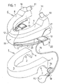
- FIG. 1 first shows the individual components of a device.
- a shoulder fitting 1 made of a lightweight, form-elastic material, such as polystyrene or the like.
- Polystyrene is an amorphous semi-crystalline thermoplastic. This material is known for example under the trade names Lustron, Styrofoam, Styrodur, Styroflex, Sagex (in Switzerland) and Telgopor (in the Spanish-speaking world).
- this shoulder fitting may also be made of an alternative material of similar nature. It may be about a wood or plywood body, or a foamed plastic material or a blown hollow plastic body may be considered.
- the molded body is bordered by a textile material, which is replaceable, and is therefore designed, for example, as a form-fitting pocket which can be closed by means of one or more zips, or by means of Velcro fasteners or snaps around the molded body.
- the shaped body can also be coated with a suitable material that feels pleasant on the skin, and that is also easy to wash off.
- This shaped body forms the shape of a horseshoe or a U with its two legs 4,5 and at the rear lower side of a karnnel shame, transverse to the horseshoe shape or U-shape recess 2 is excluded. With this indentation 2, the fitting 1 is intended to rest on the shoulder of the person to be treated.
- the second, indispensable part of the device is the head fitting 6, which may also be enclosed by a textile bag or bordered by a fabric or coated. This is made of the same material as the shoulder-shaped piece and also forms the shape of a horseshoe or U's.
- the underside 7 of this head-shaped piece 6 is flat, while it has on the top against the rear side of the two legs 8,9 each have an increase 10, on the inner upper side of each a hump 11 obliquely protrudes upwards.
- a recess 12 is formed, in which fits the chin of a person to be treated.
- the humps 11 also form support points, namely for the lower edge of the skull, left and right of the cervical spine, so that so a three-point support of the head or skull is achieved with the chin on top of the head molding 6.
- these bumps 11 may be made as a separate cylindrical parts of a rubber, plastic, wood or polystyrene, and they are then inserted into corresponding holes on the two legs of the fitting 6.
- different height bumps 11 can be used, depending on the anatomical conditions in the person to be treated.
- the top or bearing surface of the bumps 11 can be adapted even better by cutting to the support on the skull, so that a comfortable fit is achieved.
- This head fitting 6 may also be constructed to consist essentially of a U-shaped bent metal profile having a pad cushion padding on the front.
- This chin rest can be attached to the profile height adjustable by means of screws, so that the chin rest is customizable.
- the screw about their position, their Anstell-angle and are adjustable in height.
- a hinge can be installed, so that the two legs are adjustable in their pivotal position.
- the length of the two laterally extending profiles or legs is also adjustable, for example, by these overlap there or are telescopically guided into each other and in each extension position are fixed to each other.
- the length of the head-shaped piece 6 as a whole, as well as the position and height of the chin rest and the two humps can be individually and exactly adapted to each person.
- a lifting device to the device, which acts between the two superimposed mold pieces 1.6 and makes the head molding 6 from the lower shoulder fitting 1 can be raised.
- the easiest and best is a pneumatic lifting device. It consists in the example shown of two air bags 13, which are inserted on the two rear sides of the device between the legs 8,9 of the upper 6 and lower mold piece 1. These two air bags 13 are connected to each other via a hose 17 and inflatable via a further hose 14 by a rubber bellows 15 is mounted at the end.
- a pressure-relief valve 18 is installed in the hose 14, with a spring-loaded push-button for opening the valve 18.
- a pressure gauge 16 can be installed in the hose 14 to indicate the air pressure prevailing in the cushions 13.
- the device also includes a V-shaped intermediate plate 19 made of plastic, sheet metal or plywood. This includes an acute angle seen from the side and their outer edges 20 extend along the outer contour of the other two pieces, namely the shoulder 1 and the head piece 6.
- This intermediate plate 19 has on its upper leg on the rear side outside each one after upwardly projecting ear 21, and optionally also on the lower leg of the plate depending on a downwardly projecting ear 22, so that the head-shaped piece 6 is held between these two ears 21 or at least out, and the shoulder-shaped piece 1 in an easy way between the downwardly projecting ears 22.
- This device is now designed so that first the shoulder fitting 1 is pushed from the front onto the shoulders of a person to be treated.
- this person can easily create this fitting 1 as well as the whole device itself.
- the shoulder fitting 1 is put on, the head fitting 6 is pushed from the front onto the flat upper side of the shoulder fitting 1.
- the two legs 8,9 again have to be slightly spread apart from each other and then be closed again by releasing elastic.
- the person's chin lies on the recess 12 on the head fitting 6, and the two bumps 11 on the rear upper side of the legs 8, 9 support the lower edge of the skull on its rear side. As a result, a clean three-point support is formed.
- the intermediate plate 19, which has a similar horseshoe shape when viewed from above, is inserted from the front between the shoulder fitting 1 and the head fitting 6.
- This inflation should be done consciously by the person himself, because this can be very finely dosed by pumping her pleasant or just bearable tension on her cervical spine produce. Conversely, if needed or in the case of an acute onset of pain, it can immediately reduce or eliminate this tension again by operating the one-way relief valve 18, for which purpose it merely relies on the patient corresponding spring-loaded push button needs to press.
- This device shown here can also be used without the intermediate plate 19. In this case, the air cushion 13 are inserted directly between the rear portions of the legs 4.8 and 5.9 of the two fittings 1.6.
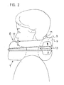
- FIG. 2 you can see the device applied to a person to be treated, seen from the side.
- the lower shoulder fitting 1 rests on the shoulder while the upper fitting 6, namely the head fitting 6, supports the person's head at three points, namely on the chin by the recess 12, as well as at the lower rear edge of the skull Bump 11 on the top of the legs 8.9 of the head molding 6.
- the air cushion 13 are inserted. It may also be a single air cushion 13, which extends across the width of the device, that is inserted transversely behind the neck of the person extending between the two legs of the two fittings 1.6.
- the air cushion 13 can be secured by means of Velcro strips attached to them against slipping on the lower fitting 1, for example.
- the two shaped pieces 1, 6 are spread away from one another with their rear ends, as shown by the arrows, while they rest on each other in front. Depending on the expansion position, the spine of the person being treated is more or less relieved in the neck area.
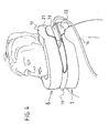
- FIG. 3 shows the device applied to a person to be treated, seen from obliquely behind. It can be seen that the two shaped pieces 1, 6 are open on the rear side, because there the two legs 4, 5 of the shaped pieces 1, 6 end. Due to the nature of the material of the fittings 1.6 their legs can be slightly spread apart, which facilitates the application of the first shoulder-shaped piece 1 and then the head-shoulder piece 6. The bulge 2 for the shoulder of the person ensures the good fit of the shoulder molding 1 and the head molding 6, the three-point pad is important.
- FIG. 4 If the device is attached to a person to be treated, seen diagonally from the front.
- the rounding on the inner side of the head molding 6 creates enough rum for the cheeks and neck.
- this space is particularly needed.
- Relieving and relieving the cervical spine, as confirmed by many physiotherapists, is particularly helpful and beneficial to well-being.
- This therapy can be extremely effective and extremely simple and convenient to perform with the presented device, and that of the person to be treated.
- the FIG. 5 It consists of a head-side mold plate 23, which forms two legs 33,34, a longer leg 33 and a shorter leg 34, which are connected to each other via a hinge 27 pivotally connected to each other. At their ends run these legs 33,34 in each case a circular support plate 35 here.
- This entire mold plate 23 may be made of a plastic plate, or of a strong foam plate, which may be coated so that it is washable and thus easy to clean.
- a latch bolt 25 is firmly attached with its local end. It extends to the opposite leg 33 and is formed in its center in an arc, so that its inner side forms a padded funnel-shaped support surface, of which thus a neck support 26 is formed.
- a chin rest 30 is attached to the leg 33. This sits on a displaceable along the arrows drawn adjusting plate 32, which carries an upwardly projecting, soft-elastic chin pad 31.
- the chin rest 30 is adapted to the chin of the person to be treated and then secured in the correct position. Then the chin pad sits 31 full on the chin of the person and supports it.
- a breast support pad 37 Down on the leg 33, below the chin rest 30, there is a breast support pad 37 which is held by a length adjustable bracket 38 which is secured to the leg 33 at the bottom. This bracket 38 can be adjusted so far until the end-side breast support pad 37 rests against the sternum of the person to be treated and the device is supported against the chest.
- this device is shown in application position, ie with closed legs 33,34.
- an elastic plastic plate 28 is attached, but only in the region of the curved legs 33,34.
- the plastic plate 28 Towards the end-side support plates 35, the plastic plate 28 is loose and can therefore be bent slightly downward relative to the support plate 35.
- an air cushion 13 is attached, which has approximately the same basic shape without air as the overlying support plate 35. It is supplied via a hose 14 with air.
- This hose 14 is equipped on one side with a rubber bellows 15. By squeezing air is pumped into the air bag 13 and the plastic plate 28 is spread away from the support plate 35.
- cylindrical foam pad 24 are attached, for example by means of Velcro or snaps. These foam pads 24 come to rest in the application position on the shoulders of the person to be treated. They can be replaced by more or less high pads, so that in each patient an optimal fitting position of the device can be achieved.
- the device is then applied well to a person when her neck is full of the Neck support 26 is supported, the chin rests satisfactorily on the chin pad 31 and the device is supported with the breast pad 37 on the breastbone. By inflating the air cushion then the neck is gently raised by a support on the two shoulders.
Landscapes
- Health & Medical Sciences (AREA)
- Nursing (AREA)
- Orthopedic Medicine & Surgery (AREA)
- Engineering & Computer Science (AREA)
- Biomedical Technology (AREA)
- Heart & Thoracic Surgery (AREA)
- Vascular Medicine (AREA)
- Life Sciences & Earth Sciences (AREA)
- Animal Behavior & Ethology (AREA)
- General Health & Medical Sciences (AREA)
- Public Health (AREA)
- Veterinary Medicine (AREA)
- Orthopedics, Nursing, And Contraception (AREA)
Abstract
Claims (6)
- Dispositif pour soulager et soigner la colonne vertébrale cervicale composé d'une surface d'appui pour l'épaule et d'une surface d'appui pour la tête susceptible d'être soulevée pour la zone du cou et du menton et composé également de moyens élévateurs (13) pneumatiques avec un coussin d'air situé entre la zone arrière de la surface d'appui pour l'épaule et la surface d'appui pour la tête ainsi que le ballon en caoutchouc (15) associé pour pomper, et caractérisé en ce que,
la surface d'appui de la tête est composée d'une plaque de formage (23) composée de deux branches (33, 34), susceptibles d'être pivotées l'une par rapport à l'autre, avec des plaque d'appui (35) terminales, lesquelles plaques sont susceptibles d'être liées l'une par rapport à l'autre par liaison de force, et en ce que la surface d'appui pour l'épaule est formée par deux plaques en matière plastique (28) qui sont fixées sur le côté inférieur des branches (33, 34) et qui sont susceptibles d'être écartées desdites branches ou susceptibles d'être pivoté en l'écartant comme une charnière desdites branches et lesquelles plaques en matière plastique portent sur leur côté supérieur en-dessous des plaques d'appui (35) à chaque fois un coussin d'air et lesquelles plaques sont équipées sur leur côté inférieur situé en-dessous des coussins d'air (13) d'épaulettes de protection (24) fixées de façon mobile. - Dispositif pour soulager et soigner la colonne vertébrale cervicale selon la revendication 1, caractérisé en ce que, la surface d'appui pour l'épaule est fixée sur le côté inférieur des branches (33, 34) de manière à ce qu'une charnière de pivotement, de manière à ce que les branches (33, 34) puissent être pivotées par rapport à la surface d'appui pour l'épaule autour d'un axe de pivotement s'étendant à peu près dans le plan de la surface d'appui pour l'épaule.
- Dispositif pour soulager et soigner la colonne vertébrale cervicale selon une des revendications précédentes, caractérisé en ce que les deux branches (33, 34), susceptibles d'être pivotées l'une par rapport à l'autre, peuvent être liées l'une à l'autre de façon par liaison de force via un verrou de fermeture (25) fixée à ladite branche (34).
- Dispositif pour soulager et soigner la colonne vertébrale cervicale selon une des revendications précédentes, caractérisé en ce que les deux branches (33, 34), susceptibles d'être pivotées l'une par rapport à l'autre, peuvent être liées l'une à l'autre de façon par liaison de force via un verrou de fermeture (25) fixée à ladite branche (34), lequel verrou de fermeture (25) forme dans un état de fermeture des branches (33, 34) un appui pour le cou (26).
- Dispositif pour soulager et soigner la colonne vertébrale cervicale selon une des revendications précédentes, caractérisé en ce qu'un coussin pour le menton (31) réglable est fixé sur une branche (33) sur le côté supérieur de ladite branche, et en ce qu'un coussin de protection pour la poitrine (37) réglable en hauteur est fixé sur le côté inférieur de ladite branche.
- Dispositif pour soulager et soigner la colonne vertébrale cervicale selon une des revendications précédentes, caractérisé en ce que la surface d'appui pour la tête forme dans l'état de fermeture des branches (22, 23) et lorsque le verrou de fermeture (25) est encliqueté, une surface d'appui pour le bord du crâne arrière inférieur et le coussin pour le menton (31) forme une surface d'appui pour le menton afin de réaliser un support multipoint stable et défini pour la tête.
Applications Claiming Priority (2)
| Application Number | Priority Date | Filing Date | Title |
|---|---|---|---|
| CH00348/07A CH698561B1 (de) | 2007-03-02 | 2007-03-02 | Vorrichtung zum Entlasten und Therapieren der cervicalen Wirbelsäule. |
| PCT/EP2008/052504 WO2008107392A1 (fr) | 2007-03-02 | 2008-02-29 | Dispositif pour soulager et soigner la colonne vertébrale cervicale |
Publications (2)
| Publication Number | Publication Date |
|---|---|
| EP2114325A1 EP2114325A1 (fr) | 2009-11-11 |
| EP2114325B1 true EP2114325B1 (fr) | 2012-08-22 |
Family
ID=39382022
Family Applications (1)
| Application Number | Title | Priority Date | Filing Date |
|---|---|---|---|
| EP08717284A Not-in-force EP2114325B1 (fr) | 2007-03-02 | 2008-02-29 | Dispositif pour soulager et soigner la colonne vertébrale cervicale |
Country Status (4)
| Country | Link |
|---|---|
| US (1) | US8303626B2 (fr) |
| EP (1) | EP2114325B1 (fr) |
| CH (1) | CH698561B1 (fr) |
| WO (1) | WO2008107392A1 (fr) |
Families Citing this family (8)
| Publication number | Priority date | Publication date | Assignee | Title |
|---|---|---|---|---|
| EP2186481A1 (fr) * | 2008-11-17 | 2010-05-19 | Medison Co., Ltd. | Sonde à ultrasons capable de détecter une surface courbe |
| TWI397406B (zh) * | 2010-01-08 | 2013-06-01 | Univ China Medical | 充氣式自動頸椎活動裝置 |
| US9192503B1 (en) * | 2011-07-05 | 2015-11-24 | Peter W. Peterson | Mechanical massage and traction apparatus |
| CN102989122B (zh) * | 2011-09-15 | 2014-12-17 | 宁波市镇海西门专利技术开发有限公司 | 充气踏步毯 |
| WO2013059817A1 (fr) * | 2011-10-21 | 2013-04-25 | Murer Kenneth H | Système de traction cervicale basé sur la flottabilité |
| US20220287865A1 (en) * | 2018-11-20 | 2022-09-15 | Tate Technology, Llc | Inflatable cervical collar neck system |
| US10694854B1 (en) * | 2018-12-06 | 2020-06-30 | Song Lin | Portable gravity reducing apparatus for sitting positions |
| US11432653B1 (en) * | 2022-03-11 | 2022-09-06 | Eric Gormeley | System, apparatus, and method for supporting a user's body |
Family Cites Families (11)
| Publication number | Priority date | Publication date | Assignee | Title |
|---|---|---|---|---|
| US5713841A (en) * | 1993-02-12 | 1998-02-03 | Graham; Richard A. | Inflatable cervical cervico-thoracic thoraco-lumbar and lumbar exercising device |
| US5441479A (en) * | 1993-09-13 | 1995-08-15 | Glacier Cross, Inc. | Cervical traction device |
| US5709649A (en) * | 1993-09-13 | 1998-01-20 | Glacier Cross, Inc. | Neck curvature alignment device |
| US5662597A (en) * | 1993-09-13 | 1997-09-02 | Glacier Cross, Inc. | Gravity traction device |
| US5752927A (en) * | 1995-12-29 | 1998-05-19 | Rogachevsky; Richard J. | Inflatable cervical traction device |
| DE29613213U1 (de) | 1996-07-31 | 1996-10-31 | Baumann, Friedrich, 83080 Oberaudorf | Medizinische Halskrawatte |
| AU6585398A (en) | 1997-03-28 | 1998-10-22 | Jason P. Feingold | Cervical collar |
| US6447468B1 (en) | 2001-08-08 | 2002-09-10 | James T. Hankins | Portable cervical traction apparatus |
| WO2003079941A1 (fr) | 2002-03-22 | 2003-10-02 | Jung-Min Han | Dispositif de traction pour les vertebres cervicales |
| CA2601909A1 (fr) | 2005-03-24 | 2006-09-28 | Richard J. Rogachevsky | Dispositif de traction en spirale gonflable, systeme et methode associes |
| US7670307B2 (en) * | 2008-02-08 | 2010-03-02 | International Rehabilitative Sciences, Inc. | Cervical traction/stretch device kit |
-
2007
- 2007-03-02 CH CH00348/07A patent/CH698561B1/de not_active IP Right Cessation
-
2008
- 2008-02-29 US US12/529,510 patent/US8303626B2/en not_active Expired - Fee Related
- 2008-02-29 EP EP08717284A patent/EP2114325B1/fr not_active Not-in-force
- 2008-02-29 WO PCT/EP2008/052504 patent/WO2008107392A1/fr active Application Filing
Also Published As
| Publication number | Publication date |
|---|---|
| US8303626B2 (en) | 2012-11-06 |
| CH698561B1 (de) | 2009-08-31 |
| WO2008107392A1 (fr) | 2008-09-12 |
| EP2114325A1 (fr) | 2009-11-11 |
| US20100094342A1 (en) | 2010-04-15 |
Similar Documents
| Publication | Publication Date | Title |
|---|---|---|
| EP2114325B1 (fr) | Dispositif pour soulager et soigner la colonne vertébrale cervicale | |
| EP0967114B1 (fr) | Dispositif pour s'asseoir et/ou s'allonger, en particulier siège de véhicule ou d'avion | |
| DE1554084C3 (de) | Sitz, insbesondere Kraftfahrzeugsitz | |
| DE2502202B2 (de) | Stützmieder | |
| DE2837620A1 (de) | Rueckenstuetzbandage | |
| DE3315929A1 (de) | Schwerkraftstreckapparat | |
| EP2785215B1 (fr) | Siège à fonction de soutien corporel | |
| WO1998049979A1 (fr) | Orthese pivotante pour fracture | |
| DE3905115B4 (de) | Orthopädische Halskrawatte mit einer pneumatischen Expansionsvorrichtung | |
| DE2211015A1 (de) | Tragbahre zum Transport von Personen, insbesondere mit'Wirbelsäulenverletzungen oder Brüchen des Oberschenkelhalsknochens | |
| DE2344534A1 (de) | Transportable rueckenstuetze | |
| DE3685880T2 (de) | Sitzmoebel mit aufblasbaren kammern fuer massagezwecke. | |
| EP1491169B1 (fr) | Minerve | |
| DE2343020C2 (de) | Orthopädische und der Entspannung dienende Vorrichtung | |
| DE2410839A1 (de) | Vorrichtung zum entlastethalten des menschlichen koerpers | |
| DE3045386A1 (de) | Rueckenunterstuetzung fuer einen sitz, insbesondere fuer einen fahrzeugsitz | |
| EP1220627B1 (fr) | Coussin gonflable | |
| DE69008888T2 (de) | System zum Bewegen, Stützen und Stimulieren des menschlichen Körpers in einer sitzenden Position. | |
| DE102007012557B3 (de) | Bauchspanngurt | |
| DE1541285A1 (de) | Orthopaedische Stuetzeinrichtung | |
| DE19919365C2 (de) | Stützkissen für eine Sitz- oder Liegevorrichtung | |
| DE20112331U1 (de) | Flexibles Lagerungssystem | |
| EP3603753B1 (fr) | Équipement sportif | |
| DE29714633U1 (de) | Mobiles Trainingsgerät und Trainingsset für den menschlichen Körper zur Verwendung in einem KFZ oder auf sonstigen Sitzgelegenheiten | |
| EP3213733B1 (fr) | Dispositif de mobilisation de vertèbres |
Legal Events
| Date | Code | Title | Description |
|---|---|---|---|
| PUAI | Public reference made under article 153(3) epc to a published international application that has entered the european phase |
Free format text: ORIGINAL CODE: 0009012 |
|
| 17P | Request for examination filed |
Effective date: 20090824 |
|
| AK | Designated contracting states |
Kind code of ref document: A1 Designated state(s): AT BE BG CH CY CZ DE DK EE ES FI FR GB GR HR HU IE IS IT LI LT LU LV MC MT NL NO PL PT RO SE SI SK TR |
|
| RAP1 | Party data changed (applicant data changed or rights of an application transferred) |
Owner name: CURACERES GMBH |
|
| RIN1 | Information on inventor provided before grant (corrected) |
Inventor name: FISCHER, PAUL WALTER |
|
| DAX | Request for extension of the european patent (deleted) | ||
| RIC1 | Information provided on ipc code assigned before grant |
Ipc: A61F 5/055 20060101AFI20120222BHEP |
|
| GRAP | Despatch of communication of intention to grant a patent |
Free format text: ORIGINAL CODE: EPIDOSNIGR1 |
|
| GRAS | Grant fee paid |
Free format text: ORIGINAL CODE: EPIDOSNIGR3 |
|
| GRAA | (expected) grant |
Free format text: ORIGINAL CODE: 0009210 |
|
| AK | Designated contracting states |
Kind code of ref document: B1 Designated state(s): AT BE BG CH CY CZ DE DK EE ES FI FR GB GR HR HU IE IS IT LI LT LU LV MC MT NL NO PL PT RO SE SI SK TR |
|
| REG | Reference to a national code |
Ref country code: GB Ref legal event code: FG4D Free format text: NOT ENGLISH |
|
| REG | Reference to a national code |
Ref country code: CH Ref legal event code: EP |
|
| REG | Reference to a national code |
Ref country code: IE Ref legal event code: FG4D Free format text: LANGUAGE OF EP DOCUMENT: GERMAN |
|
| REG | Reference to a national code |
Ref country code: AT Ref legal event code: REF Ref document number: 571517 Country of ref document: AT Kind code of ref document: T Effective date: 20120915 |
|
| REG | Reference to a national code |
Ref country code: DE Ref legal event code: R096 Ref document number: 502008008011 Country of ref document: DE Effective date: 20121018 |
|
| REG | Reference to a national code |
Ref country code: NL Ref legal event code: T3 |
|
| REG | Reference to a national code |
Ref country code: LT Ref legal event code: MG4D Effective date: 20120822 |
|
| PG25 | Lapsed in a contracting state [announced via postgrant information from national office to epo] |
Ref country code: LT Free format text: LAPSE BECAUSE OF FAILURE TO SUBMIT A TRANSLATION OF THE DESCRIPTION OR TO PAY THE FEE WITHIN THE PRESCRIBED TIME-LIMIT Effective date: 20120822 Ref country code: HR Free format text: LAPSE BECAUSE OF FAILURE TO SUBMIT A TRANSLATION OF THE DESCRIPTION OR TO PAY THE FEE WITHIN THE PRESCRIBED TIME-LIMIT Effective date: 20120822 Ref country code: FI Free format text: LAPSE BECAUSE OF FAILURE TO SUBMIT A TRANSLATION OF THE DESCRIPTION OR TO PAY THE FEE WITHIN THE PRESCRIBED TIME-LIMIT Effective date: 20120822 Ref country code: NO Free format text: LAPSE BECAUSE OF FAILURE TO SUBMIT A TRANSLATION OF THE DESCRIPTION OR TO PAY THE FEE WITHIN THE PRESCRIBED TIME-LIMIT Effective date: 20121122 Ref country code: IS Free format text: LAPSE BECAUSE OF FAILURE TO SUBMIT A TRANSLATION OF THE DESCRIPTION OR TO PAY THE FEE WITHIN THE PRESCRIBED TIME-LIMIT Effective date: 20121222 |
|
| PG25 | Lapsed in a contracting state [announced via postgrant information from national office to epo] |
Ref country code: SI Free format text: LAPSE BECAUSE OF FAILURE TO SUBMIT A TRANSLATION OF THE DESCRIPTION OR TO PAY THE FEE WITHIN THE PRESCRIBED TIME-LIMIT Effective date: 20120822 Ref country code: SE Free format text: LAPSE BECAUSE OF FAILURE TO SUBMIT A TRANSLATION OF THE DESCRIPTION OR TO PAY THE FEE WITHIN THE PRESCRIBED TIME-LIMIT Effective date: 20120822 Ref country code: LV Free format text: LAPSE BECAUSE OF FAILURE TO SUBMIT A TRANSLATION OF THE DESCRIPTION OR TO PAY THE FEE WITHIN THE PRESCRIBED TIME-LIMIT Effective date: 20120822 Ref country code: GR Free format text: LAPSE BECAUSE OF FAILURE TO SUBMIT A TRANSLATION OF THE DESCRIPTION OR TO PAY THE FEE WITHIN THE PRESCRIBED TIME-LIMIT Effective date: 20121123 Ref country code: PT Free format text: LAPSE BECAUSE OF FAILURE TO SUBMIT A TRANSLATION OF THE DESCRIPTION OR TO PAY THE FEE WITHIN THE PRESCRIBED TIME-LIMIT Effective date: 20121224 |
|
| PG25 | Lapsed in a contracting state [announced via postgrant information from national office to epo] |
Ref country code: RO Free format text: LAPSE BECAUSE OF FAILURE TO SUBMIT A TRANSLATION OF THE DESCRIPTION OR TO PAY THE FEE WITHIN THE PRESCRIBED TIME-LIMIT Effective date: 20120822 Ref country code: CZ Free format text: LAPSE BECAUSE OF FAILURE TO SUBMIT A TRANSLATION OF THE DESCRIPTION OR TO PAY THE FEE WITHIN THE PRESCRIBED TIME-LIMIT Effective date: 20120822 Ref country code: ES Free format text: LAPSE BECAUSE OF FAILURE TO SUBMIT A TRANSLATION OF THE DESCRIPTION OR TO PAY THE FEE WITHIN THE PRESCRIBED TIME-LIMIT Effective date: 20121203 Ref country code: DK Free format text: LAPSE BECAUSE OF FAILURE TO SUBMIT A TRANSLATION OF THE DESCRIPTION OR TO PAY THE FEE WITHIN THE PRESCRIBED TIME-LIMIT Effective date: 20120822 Ref country code: EE Free format text: LAPSE BECAUSE OF FAILURE TO SUBMIT A TRANSLATION OF THE DESCRIPTION OR TO PAY THE FEE WITHIN THE PRESCRIBED TIME-LIMIT Effective date: 20120822 |
|
| PG25 | Lapsed in a contracting state [announced via postgrant information from national office to epo] |
Ref country code: CY Free format text: LAPSE BECAUSE OF FAILURE TO SUBMIT A TRANSLATION OF THE DESCRIPTION OR TO PAY THE FEE WITHIN THE PRESCRIBED TIME-LIMIT Effective date: 20120822 Ref country code: SK Free format text: LAPSE BECAUSE OF FAILURE TO SUBMIT A TRANSLATION OF THE DESCRIPTION OR TO PAY THE FEE WITHIN THE PRESCRIBED TIME-LIMIT Effective date: 20120822 Ref country code: PL Free format text: LAPSE BECAUSE OF FAILURE TO SUBMIT A TRANSLATION OF THE DESCRIPTION OR TO PAY THE FEE WITHIN THE PRESCRIBED TIME-LIMIT Effective date: 20120822 Ref country code: IT Free format text: LAPSE BECAUSE OF FAILURE TO SUBMIT A TRANSLATION OF THE DESCRIPTION OR TO PAY THE FEE WITHIN THE PRESCRIBED TIME-LIMIT Effective date: 20120822 |
|
| PLBE | No opposition filed within time limit |
Free format text: ORIGINAL CODE: 0009261 |
|
| STAA | Information on the status of an ep patent application or granted ep patent |
Free format text: STATUS: NO OPPOSITION FILED WITHIN TIME LIMIT |
|
| 26N | No opposition filed |
Effective date: 20130523 |
|
| PG25 | Lapsed in a contracting state [announced via postgrant information from national office to epo] |
Ref country code: BG Free format text: LAPSE BECAUSE OF FAILURE TO SUBMIT A TRANSLATION OF THE DESCRIPTION OR TO PAY THE FEE WITHIN THE PRESCRIBED TIME-LIMIT Effective date: 20121122 |
|
| REG | Reference to a national code |
Ref country code: DE Ref legal event code: R097 Ref document number: 502008008011 Country of ref document: DE Effective date: 20130523 |
|
| REG | Reference to a national code |
Ref country code: CH Ref legal event code: PL |
|
| PG25 | Lapsed in a contracting state [announced via postgrant information from national office to epo] |
Ref country code: CH Free format text: LAPSE BECAUSE OF NON-PAYMENT OF DUE FEES Effective date: 20130228 Ref country code: LI Free format text: LAPSE BECAUSE OF NON-PAYMENT OF DUE FEES Effective date: 20130228 Ref country code: MC Free format text: LAPSE BECAUSE OF NON-PAYMENT OF DUE FEES Effective date: 20130331 |
|
| REG | Reference to a national code |
Ref country code: IE Ref legal event code: MM4A |
|
| PG25 | Lapsed in a contracting state [announced via postgrant information from national office to epo] |
Ref country code: IE Free format text: LAPSE BECAUSE OF NON-PAYMENT OF DUE FEES Effective date: 20130228 |
|
| PG25 | Lapsed in a contracting state [announced via postgrant information from national office to epo] |
Ref country code: MT Free format text: LAPSE BECAUSE OF FAILURE TO SUBMIT A TRANSLATION OF THE DESCRIPTION OR TO PAY THE FEE WITHIN THE PRESCRIBED TIME-LIMIT Effective date: 20120822 |
|
| REG | Reference to a national code |
Ref country code: CH Ref legal event code: PK Free format text: DER WEITERBEHANDLUNGSANTRAG VOM 25. FEBRUAR 2014 WURDE AM 1. JULI 2014 ABGELEHNT |
|
| REG | Reference to a national code |
Ref country code: FR Ref legal event code: PLFP Year of fee payment: 8 |
|
| PGFP | Annual fee paid to national office [announced via postgrant information from national office to epo] |
Ref country code: DE Payment date: 20150225 Year of fee payment: 8 Ref country code: LU Payment date: 20150225 Year of fee payment: 8 Ref country code: NL Payment date: 20150224 Year of fee payment: 8 |
|
| PGFP | Annual fee paid to national office [announced via postgrant information from national office to epo] |
Ref country code: GB Payment date: 20150225 Year of fee payment: 8 Ref country code: FR Payment date: 20150224 Year of fee payment: 8 Ref country code: AT Payment date: 20150225 Year of fee payment: 8 |
|
| PG25 | Lapsed in a contracting state [announced via postgrant information from national office to epo] |
Ref country code: TR Free format text: LAPSE BECAUSE OF FAILURE TO SUBMIT A TRANSLATION OF THE DESCRIPTION OR TO PAY THE FEE WITHIN THE PRESCRIBED TIME-LIMIT Effective date: 20120822 |
|
| PGFP | Annual fee paid to national office [announced via postgrant information from national office to epo] |
Ref country code: BE Payment date: 20150226 Year of fee payment: 8 |
|
| PG25 | Lapsed in a contracting state [announced via postgrant information from national office to epo] |
Ref country code: HU Free format text: LAPSE BECAUSE OF FAILURE TO SUBMIT A TRANSLATION OF THE DESCRIPTION OR TO PAY THE FEE WITHIN THE PRESCRIBED TIME-LIMIT; INVALID AB INITIO Effective date: 20080229 |
|
| PG25 | Lapsed in a contracting state [announced via postgrant information from national office to epo] |
Ref country code: BE Free format text: LAPSE BECAUSE OF NON-PAYMENT OF DUE FEES Effective date: 20160229 |
|
| REG | Reference to a national code |
Ref country code: DE Ref legal event code: R119 Ref document number: 502008008011 Country of ref document: DE |
|
| PG25 | Lapsed in a contracting state [announced via postgrant information from national office to epo] |
Ref country code: LU Free format text: LAPSE BECAUSE OF NON-PAYMENT OF DUE FEES Effective date: 20160229 |
|
| REG | Reference to a national code |
Ref country code: AT Ref legal event code: MM01 Ref document number: 571517 Country of ref document: AT Kind code of ref document: T Effective date: 20160229 |
|
| GBPC | Gb: european patent ceased through non-payment of renewal fee |
Effective date: 20160229 |
|
| REG | Reference to a national code |
Ref country code: NL Ref legal event code: MM Effective date: 20160301 |
|
| REG | Reference to a national code |
Ref country code: FR Ref legal event code: ST Effective date: 20161028 |
|
| PG25 | Lapsed in a contracting state [announced via postgrant information from national office to epo] |
Ref country code: AT Free format text: LAPSE BECAUSE OF NON-PAYMENT OF DUE FEES Effective date: 20160229 |
|
| PG25 | Lapsed in a contracting state [announced via postgrant information from national office to epo] |
Ref country code: GB Free format text: LAPSE BECAUSE OF NON-PAYMENT OF DUE FEES Effective date: 20160229 Ref country code: NL Free format text: LAPSE BECAUSE OF NON-PAYMENT OF DUE FEES Effective date: 20160301 Ref country code: FR Free format text: LAPSE BECAUSE OF NON-PAYMENT OF DUE FEES Effective date: 20160229 Ref country code: DE Free format text: LAPSE BECAUSE OF NON-PAYMENT OF DUE FEES Effective date: 20160901 |