EP2114325B1 - Vorrichtung zum entlasten und therapieren der cervicalen wirbelsäule - Google Patents
Vorrichtung zum entlasten und therapieren der cervicalen wirbelsäule Download PDFInfo
- Publication number
- EP2114325B1 EP2114325B1 EP08717284A EP08717284A EP2114325B1 EP 2114325 B1 EP2114325 B1 EP 2114325B1 EP 08717284 A EP08717284 A EP 08717284A EP 08717284 A EP08717284 A EP 08717284A EP 2114325 B1 EP2114325 B1 EP 2114325B1
- Authority
- EP
- European Patent Office
- Prior art keywords
- branches
- support
- shoulder
- head
- relieving
- Prior art date
- Legal status (The legal status is an assumption and is not a legal conclusion. Google has not performed a legal analysis and makes no representation as to the accuracy of the status listed.)
- Not-in-force
Links
- 238000002560 therapeutic procedure Methods 0.000 title abstract description 5
- 230000006837 decompression Effects 0.000 title 1
- 239000004033 plastic Substances 0.000 claims description 11
- 210000003625 skull Anatomy 0.000 claims description 6
- 210000000481 breast Anatomy 0.000 claims description 4
- 238000005086 pumping Methods 0.000 claims description 3
- 238000000465 moulding Methods 0.000 abstract description 12
- 210000002414 leg Anatomy 0.000 description 36
- 210000003739 neck Anatomy 0.000 description 24
- 239000000463 material Substances 0.000 description 7
- 239000002184 metal Substances 0.000 description 4
- 210000000689 upper leg Anatomy 0.000 description 4
- 208000002193 Pain Diseases 0.000 description 3
- 239000004793 Polystyrene Substances 0.000 description 3
- 239000006260 foam Substances 0.000 description 3
- 229920002223 polystyrene Polymers 0.000 description 3
- 239000005060 rubber Substances 0.000 description 3
- 230000001154 acute effect Effects 0.000 description 2
- 238000010276 construction Methods 0.000 description 2
- 230000006378 damage Effects 0.000 description 2
- 210000005069 ears Anatomy 0.000 description 2
- 238000007373 indentation Methods 0.000 description 2
- 239000011120 plywood Substances 0.000 description 2
- 239000007787 solid Substances 0.000 description 2
- 210000001562 sternum Anatomy 0.000 description 2
- 239000004753 textile Substances 0.000 description 2
- 230000036642 wellbeing Effects 0.000 description 2
- 208000000094 Chronic Pain Diseases 0.000 description 1
- 206010019233 Headaches Diseases 0.000 description 1
- 206010061307 Neck deformity Diseases 0.000 description 1
- 206010033372 Pain and discomfort Diseases 0.000 description 1
- 229920006328 Styrofoam Polymers 0.000 description 1
- 208000027418 Wounds and injury Diseases 0.000 description 1
- 230000009286 beneficial effect Effects 0.000 description 1
- 210000000038 chest Anatomy 0.000 description 1
- 230000003670 easy-to-clean Effects 0.000 description 1
- 239000013013 elastic material Substances 0.000 description 1
- 239000004744 fabric Substances 0.000 description 1
- 230000004886 head movement Effects 0.000 description 1
- 231100000869 headache Toxicity 0.000 description 1
- 230000035876 healing Effects 0.000 description 1
- 208000014674 injury Diseases 0.000 description 1
- 210000004237 neck muscle Anatomy 0.000 description 1
- 230000000737 periodic effect Effects 0.000 description 1
- 239000008261 styrofoam Substances 0.000 description 1
- 238000002626 targeted therapy Methods 0.000 description 1
- 230000001225 therapeutic effect Effects 0.000 description 1
- 229920001169 thermoplastic Polymers 0.000 description 1
- 239000004416 thermosoftening plastic Substances 0.000 description 1
- 230000001960 triggered effect Effects 0.000 description 1
- 239000002023 wood Substances 0.000 description 1
Images


Classifications
-
- A—HUMAN NECESSITIES
- A61—MEDICAL OR VETERINARY SCIENCE; HYGIENE
- A61F—FILTERS IMPLANTABLE INTO BLOOD VESSELS; PROSTHESES; DEVICES PROVIDING PATENCY TO, OR PREVENTING COLLAPSING OF, TUBULAR STRUCTURES OF THE BODY, e.g. STENTS; ORTHOPAEDIC, NURSING OR CONTRACEPTIVE DEVICES; FOMENTATION; TREATMENT OR PROTECTION OF EYES OR EARS; BANDAGES, DRESSINGS OR ABSORBENT PADS; FIRST-AID KITS
- A61F5/00—Orthopaedic methods or devices for non-surgical treatment of bones or joints; Nursing devices ; Anti-rape devices
- A61F5/01—Orthopaedic devices, e.g. long-term immobilising or pressure directing devices for treating broken or deformed bones such as splints, casts or braces
- A61F5/04—Devices for stretching or reducing fractured limbs; Devices for distractions; Splints
- A61F5/05—Devices for stretching or reducing fractured limbs; Devices for distractions; Splints for immobilising
- A61F5/055—Cervical collars
-
- A—HUMAN NECESSITIES
- A61—MEDICAL OR VETERINARY SCIENCE; HYGIENE
- A61F—FILTERS IMPLANTABLE INTO BLOOD VESSELS; PROSTHESES; DEVICES PROVIDING PATENCY TO, OR PREVENTING COLLAPSING OF, TUBULAR STRUCTURES OF THE BODY, e.g. STENTS; ORTHOPAEDIC, NURSING OR CONTRACEPTIVE DEVICES; FOMENTATION; TREATMENT OR PROTECTION OF EYES OR EARS; BANDAGES, DRESSINGS OR ABSORBENT PADS; FIRST-AID KITS
- A61F5/00—Orthopaedic methods or devices for non-surgical treatment of bones or joints; Nursing devices ; Anti-rape devices
- A61F5/01—Orthopaedic devices, e.g. long-term immobilising or pressure directing devices for treating broken or deformed bones such as splints, casts or braces
- A61F5/0102—Orthopaedic devices, e.g. long-term immobilising or pressure directing devices for treating broken or deformed bones such as splints, casts or braces specially adapted for correcting deformities of the limbs or for supporting them; Ortheses, e.g. with articulations
- A61F5/012—Orthopaedic devices, e.g. long-term immobilising or pressure directing devices for treating broken or deformed bones such as splints, casts or braces specially adapted for correcting deformities of the limbs or for supporting them; Ortheses, e.g. with articulations inflatable
Definitions
- the present invention relates to a device to relieve the spine in the cervical area and to treat them regularly.
- Many people suffer from headaches that are often triggered by the spine, especially the neck area of the spine, ie the cervical area.
- the spine in the neck area must constantly carry the weight of the head and absorb and absorb all moments that emanate from head movements. Accordingly, it is loaded and extremely sensitive to damage due to accidents or wear.
- Several constructions are known in the prior art, but these are mainly neck supports. Thus, for example, reveals DE 296 13 213 U1 which is recognized as the closest prior art, a medical Halskrawatte with a number of air chambers for metered inflation.
- WO98 / 43568 shows a device that can not be created and operated by the patient. It serves only for the stationary support of the head, but not for the effective therapeutic use of the cervical spine on train. Finally shows W02006 / 102602 a device for stretching the cervical spine and also the spine. The device allows many functions, but is due to its design and elaborate design intended only for a stationary use and hardly suitable to be taken anywhere and it is not suitable to be quickly and easily created by a single person to be treated. Therefore, the previously known solutions are not able to satisfy in every respect.
- a device and a device with which a person with such from the neck area of the spine caused pain and discomfort strained person even simple and ambulant, relieve his spine in the neck area easy, targeted and individually adjustable at home or even while traveling while traveling and also can treat.
- Physiotherapists confirm that relieving, and especially periodically relieving and straining, is very conducive to well-being and a healing process. This fact has been confirmed and substantiated by practical experience.
- the object of the present invention is therefore to provide a device for relieving and treating the cervical spine, which can be used simply and on an outpatient, at home or even on the road, and which allows a targeted, individually adjustable relief of the spine in the neck area.
- the device should also allow a targeted therapy, namely a periodic relieving and reloading the Spine in the neck area.
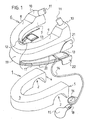
- FIG. 1 first shows the individual components of a device.
- a shoulder fitting 1 made of a lightweight, form-elastic material, such as polystyrene or the like.
- Polystyrene is an amorphous semi-crystalline thermoplastic. This material is known for example under the trade names Lustron, Styrofoam, Styrodur, Styroflex, Sagex (in Switzerland) and Telgopor (in the Spanish-speaking world).
- this shoulder fitting may also be made of an alternative material of similar nature. It may be about a wood or plywood body, or a foamed plastic material or a blown hollow plastic body may be considered.
- the molded body is bordered by a textile material, which is replaceable, and is therefore designed, for example, as a form-fitting pocket which can be closed by means of one or more zips, or by means of Velcro fasteners or snaps around the molded body.
- the shaped body can also be coated with a suitable material that feels pleasant on the skin, and that is also easy to wash off.
- This shaped body forms the shape of a horseshoe or a U with its two legs 4,5 and at the rear lower side of a karnnel shame, transverse to the horseshoe shape or U-shape recess 2 is excluded. With this indentation 2, the fitting 1 is intended to rest on the shoulder of the person to be treated.
- the second, indispensable part of the device is the head fitting 6, which may also be enclosed by a textile bag or bordered by a fabric or coated. This is made of the same material as the shoulder-shaped piece and also forms the shape of a horseshoe or U's.
- the underside 7 of this head-shaped piece 6 is flat, while it has on the top against the rear side of the two legs 8,9 each have an increase 10, on the inner upper side of each a hump 11 obliquely protrudes upwards.
- a recess 12 is formed, in which fits the chin of a person to be treated.
- the humps 11 also form support points, namely for the lower edge of the skull, left and right of the cervical spine, so that so a three-point support of the head or skull is achieved with the chin on top of the head molding 6.
- these bumps 11 may be made as a separate cylindrical parts of a rubber, plastic, wood or polystyrene, and they are then inserted into corresponding holes on the two legs of the fitting 6.
- different height bumps 11 can be used, depending on the anatomical conditions in the person to be treated.
- the top or bearing surface of the bumps 11 can be adapted even better by cutting to the support on the skull, so that a comfortable fit is achieved.
- This head fitting 6 may also be constructed to consist essentially of a U-shaped bent metal profile having a pad cushion padding on the front.
- This chin rest can be attached to the profile height adjustable by means of screws, so that the chin rest is customizable.
- the screw about their position, their Anstell-angle and are adjustable in height.
- a hinge can be installed, so that the two legs are adjustable in their pivotal position.
- the length of the two laterally extending profiles or legs is also adjustable, for example, by these overlap there or are telescopically guided into each other and in each extension position are fixed to each other.
- the length of the head-shaped piece 6 as a whole, as well as the position and height of the chin rest and the two humps can be individually and exactly adapted to each person.
- a lifting device to the device, which acts between the two superimposed mold pieces 1.6 and makes the head molding 6 from the lower shoulder fitting 1 can be raised.
- the easiest and best is a pneumatic lifting device. It consists in the example shown of two air bags 13, which are inserted on the two rear sides of the device between the legs 8,9 of the upper 6 and lower mold piece 1. These two air bags 13 are connected to each other via a hose 17 and inflatable via a further hose 14 by a rubber bellows 15 is mounted at the end.
- a pressure-relief valve 18 is installed in the hose 14, with a spring-loaded push-button for opening the valve 18.
- a pressure gauge 16 can be installed in the hose 14 to indicate the air pressure prevailing in the cushions 13.
- the device also includes a V-shaped intermediate plate 19 made of plastic, sheet metal or plywood. This includes an acute angle seen from the side and their outer edges 20 extend along the outer contour of the other two pieces, namely the shoulder 1 and the head piece 6.
- This intermediate plate 19 has on its upper leg on the rear side outside each one after upwardly projecting ear 21, and optionally also on the lower leg of the plate depending on a downwardly projecting ear 22, so that the head-shaped piece 6 is held between these two ears 21 or at least out, and the shoulder-shaped piece 1 in an easy way between the downwardly projecting ears 22.
- This device is now designed so that first the shoulder fitting 1 is pushed from the front onto the shoulders of a person to be treated.
- this person can easily create this fitting 1 as well as the whole device itself.
- the shoulder fitting 1 is put on, the head fitting 6 is pushed from the front onto the flat upper side of the shoulder fitting 1.
- the two legs 8,9 again have to be slightly spread apart from each other and then be closed again by releasing elastic.
- the person's chin lies on the recess 12 on the head fitting 6, and the two bumps 11 on the rear upper side of the legs 8, 9 support the lower edge of the skull on its rear side. As a result, a clean three-point support is formed.
- the intermediate plate 19, which has a similar horseshoe shape when viewed from above, is inserted from the front between the shoulder fitting 1 and the head fitting 6.
- This inflation should be done consciously by the person himself, because this can be very finely dosed by pumping her pleasant or just bearable tension on her cervical spine produce. Conversely, if needed or in the case of an acute onset of pain, it can immediately reduce or eliminate this tension again by operating the one-way relief valve 18, for which purpose it merely relies on the patient corresponding spring-loaded push button needs to press.
- This device shown here can also be used without the intermediate plate 19. In this case, the air cushion 13 are inserted directly between the rear portions of the legs 4.8 and 5.9 of the two fittings 1.6.
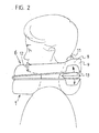
- FIG. 2 you can see the device applied to a person to be treated, seen from the side.
- the lower shoulder fitting 1 rests on the shoulder while the upper fitting 6, namely the head fitting 6, supports the person's head at three points, namely on the chin by the recess 12, as well as at the lower rear edge of the skull Bump 11 on the top of the legs 8.9 of the head molding 6.
- the air cushion 13 are inserted. It may also be a single air cushion 13, which extends across the width of the device, that is inserted transversely behind the neck of the person extending between the two legs of the two fittings 1.6.
- the air cushion 13 can be secured by means of Velcro strips attached to them against slipping on the lower fitting 1, for example.
- the two shaped pieces 1, 6 are spread away from one another with their rear ends, as shown by the arrows, while they rest on each other in front. Depending on the expansion position, the spine of the person being treated is more or less relieved in the neck area.
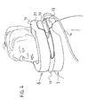
- FIG. 3 shows the device applied to a person to be treated, seen from obliquely behind. It can be seen that the two shaped pieces 1, 6 are open on the rear side, because there the two legs 4, 5 of the shaped pieces 1, 6 end. Due to the nature of the material of the fittings 1.6 their legs can be slightly spread apart, which facilitates the application of the first shoulder-shaped piece 1 and then the head-shoulder piece 6. The bulge 2 for the shoulder of the person ensures the good fit of the shoulder molding 1 and the head molding 6, the three-point pad is important.
- FIG. 4 If the device is attached to a person to be treated, seen diagonally from the front.
- the rounding on the inner side of the head molding 6 creates enough rum for the cheeks and neck.
- this space is particularly needed.
- Relieving and relieving the cervical spine, as confirmed by many physiotherapists, is particularly helpful and beneficial to well-being.
- This therapy can be extremely effective and extremely simple and convenient to perform with the presented device, and that of the person to be treated.
- the FIG. 5 It consists of a head-side mold plate 23, which forms two legs 33,34, a longer leg 33 and a shorter leg 34, which are connected to each other via a hinge 27 pivotally connected to each other. At their ends run these legs 33,34 in each case a circular support plate 35 here.
- This entire mold plate 23 may be made of a plastic plate, or of a strong foam plate, which may be coated so that it is washable and thus easy to clean.
- a latch bolt 25 is firmly attached with its local end. It extends to the opposite leg 33 and is formed in its center in an arc, so that its inner side forms a padded funnel-shaped support surface, of which thus a neck support 26 is formed.
- a chin rest 30 is attached to the leg 33. This sits on a displaceable along the arrows drawn adjusting plate 32, which carries an upwardly projecting, soft-elastic chin pad 31.
- the chin rest 30 is adapted to the chin of the person to be treated and then secured in the correct position. Then the chin pad sits 31 full on the chin of the person and supports it.
- a breast support pad 37 Down on the leg 33, below the chin rest 30, there is a breast support pad 37 which is held by a length adjustable bracket 38 which is secured to the leg 33 at the bottom. This bracket 38 can be adjusted so far until the end-side breast support pad 37 rests against the sternum of the person to be treated and the device is supported against the chest.
- this device is shown in application position, ie with closed legs 33,34.
- an elastic plastic plate 28 is attached, but only in the region of the curved legs 33,34.
- the plastic plate 28 Towards the end-side support plates 35, the plastic plate 28 is loose and can therefore be bent slightly downward relative to the support plate 35.
- an air cushion 13 is attached, which has approximately the same basic shape without air as the overlying support plate 35. It is supplied via a hose 14 with air.
- This hose 14 is equipped on one side with a rubber bellows 15. By squeezing air is pumped into the air bag 13 and the plastic plate 28 is spread away from the support plate 35.
- cylindrical foam pad 24 are attached, for example by means of Velcro or snaps. These foam pads 24 come to rest in the application position on the shoulders of the person to be treated. They can be replaced by more or less high pads, so that in each patient an optimal fitting position of the device can be achieved.
- the device is then applied well to a person when her neck is full of the Neck support 26 is supported, the chin rests satisfactorily on the chin pad 31 and the device is supported with the breast pad 37 on the breastbone. By inflating the air cushion then the neck is gently raised by a support on the two shoulders.
Landscapes
- Health & Medical Sciences (AREA)
- Nursing (AREA)
- Orthopedic Medicine & Surgery (AREA)
- Engineering & Computer Science (AREA)
- Biomedical Technology (AREA)
- Heart & Thoracic Surgery (AREA)
- Vascular Medicine (AREA)
- Life Sciences & Earth Sciences (AREA)
- Animal Behavior & Ethology (AREA)
- General Health & Medical Sciences (AREA)
- Public Health (AREA)
- Veterinary Medicine (AREA)
- Orthopedics, Nursing, And Contraception (AREA)
Abstract
Description
- Die vorliegende Erfindung betrifft eine Vorrichtung, um die Wirbelsäule im cervicalen Bereich zu entlasten und sie regelmässig zu therapieren. Viele Menschen leiden an Kopfschmerzen, die oftmals von der Wirbelsäule ausgelöst werden, vor allem vom Nackenbereich der Wirbelsäule, also dem cervicalen Bereich. Weiter gibt es viele Menschen, die Schleudertramatas erlitten haben und mit chronischen Schmerzen im Nackenbereich zu kämpfen haben. Die Wirbelsäule im Nackenbereich muss ständig das Gewicht des Kopfes tragen und alle Momente aufnehmen und absorbieren, die von Kopfbewegungen ausgehen. Entsprechend ist sie belastet und bei Schädigungen infolge Unfällen oder Abnützungen überaus empfindlich. Aus dem Stand der Technik sind mehrere Konstruktionen bekannt, welche jedoch hauptsächlich Halsstützen sind. So offenbart etwa die
DE 296 13 213 U1 der als nächter Stand der Technik anerkannt wird, eine medizinische Halskrawatte mit einer Anzahl Luftkammern zum dosierten Aufblasen. Es handelt sich um ein medizinisches Gerät, um bei Verletzungen und Beschwerden im Halswirbelsäulenbereich als Stütze verwendet zu werden, jedoch nicht um ein Gerät zum Therapieren. Es ist nicht möglich, den Kopf gewünschten Richtung zu neigen, durch Strecken der Halswirbelsäule.WO03/079941 A US 6 447 468 zeigt ein ähnliches Gerät wie hier vorgeschlagen, bei welchem aber die wichtige Abstützung des Kopfes auf seiner Vorderseite fehlt. Um eine wirksame Therapierung der Wirbelsäule zu erreichen, müssen alle Halsmuskeln völlig entspannt sein und der Drehpunkt des Kopfes beim Anheben durch das Gerät sollte vorne in der Nähe der Kinnspitze liegen.WO98/43568 W02006/102602 ein Gerät zum Strecken der Halswirbelsäule und auch der Rückenwirbelsäule. Das Gerät erlaubt viele Funktionen, ist aber aufgrund seiner Auslegung und aufwändigen Konstruktion nur für einen stationären Einsatz gedacht und kaum geeignet, überall hin mitgenommen zu werden und es eignet sich nicht, um rasch und einfach alleine von einer zu therapierenden Person selbst angelegt zu werden. Die bisher bekannt gewordenen Lösungen vermögen daher nicht in jeder Hinsicht zu befriedigen. - Bisher fehlt eine Vorrichtung und ein Gerät, mit dem ein mit solchen vom Nackenbereich der Wirbelsäule ausgelösten Schmerzen und Beschwerden belasteter Mensch selbst einfach und ambulant, bei sich zu Hause oder gar unterwegs auf Reisen seine Wirbelsäule im Nackenbereich einfach, gezielt und individuell einstellbar entlasten und auch therapieren kann. Die Physiotherapeuten bestätigen, dass eine Entlastung, und besonders periodisches Entlasten und Belasten dem Wohlbefinden und einem Heilprozess sehr förderlich sind. Dieser Sachverhalt wurde durch praktische Erfahrung bestätigt und erhärtet.
- Die Aufgabe der vorliegenden Erfindung ist es deshalb, eine Vorrichtung zum Entlasten und Therapieren der cervicalen Wirbelsäule zu schaffen, welche einfach und ambulant, zu Hause oder gar unterwegs auf Reisen einsetzbar ist, und die eine gezielte, individuell einstellbare Entlastung der Wirbelsäule im Nackenbereich ermöglicht. Die Vorrichtung soll auch ein gezieltes Therapieren ermöglichen, nämlich eine periodisches Entlasten und wieder Belasten der Wirbelsäule im Nackenbereich.
- Diese Aufgabe wird gelöst von einer Vorrichtung zum Entlasten und Therapieren der cervicalen Wirbelsäule nach dem Oberbegriff und mit den kennzeichnenden Merkmalen des Patentanspruches 1.
- Diese Vorrichtung, ihre Bestandteile und ihr Aufbau werden anhand der nachfolgenden Zeichnungen im Einzelnen beschrieben und ihre Funktion wird erläutert und erklärt.
Es zeigt: - Figur 1:
- Die einzelnen Bestandteile einer Vorrichtung getrennt voneinander und übereinander angeordnet dargestellt;
- Figur 2:
- Die Vorrichtung an eine zu therapierende Person angelegt, von der Seite her gesehen;
- Figur 3:
- Die Vorrichtung an eine zu therapierende Person angelegt, von schräg hinten gesehen;
- Figur 4:
- Die Vorrichtung an eine zu therapierende Person angelegt, von schräg vorne gesehen;
- Figur 5:
- Eine Vorrichtung gemäß der Erfindung mit geöffneten Schenkeln von oben gesehen;
- Figur 6
- Die Vorrichtung gemäß der Erfindung nach
Figur 5 geschlossen in Anwendungslage gezeigt. - Die
Figur 1 zeigt zunächst die einzelnen Bestandteile einer Vorrichtung. Diese besteht aus einem Schulter-Formstück 1 aus einem leichten, formelastischen Material, wie Polystyrol oder ähnlich. Polystyrol ist ja ein amorpher teilkristalliner Thermoplast. Bekannt ist dieses Material etwa unter den Handelsnamen Lustron, Styropor, Styrodur, Styroflex, Sagex (in der Schweiz) und Telgopor (in der spanischsprachigen Welt). Dieses Schulter-Formstück kann indessen auch aus einem alternativen Material mit ähnlicher Beschaffenheit gefertigt sein. Es kann etwa ein Holz- oder Sperrholz-Körper sein, oder ein geschäumtes Kunststoff-Material oder ein geblasener hohler Kunststoff-Körper kann in Frage kommen. Vorteilhaft ist der Formkörper von einem Textilstoff eingefasst, welcher auswechselbar ist, und daher zum Beispiel als formschlüssige Tasche ausgeführt ist, die mittels eines oder mehrer Reissverschlüsse, oder mittels Klettverschlüssen oder Druckknöpfen um den Formkörper verschliessbar ist. In einer anderen Variante kann der Formkörper auch mit einem geeigneten Material beschichtet sein, dass sich auf der Haut angenehm anfühlt, und das auch gut abwaschbar ist. Dieser Formkörper bildet die Form eines Hufeisens oder eines U's mit seinen zwei Schenkeln 4,5 und an deren hinterer unterer Seite ist eine kännelartige, quer zur Hufeisenform oder U-Form verlaufende Einbuchtung 2 ausgenommen. Mit dieser Einbuchtung 2 ist das Formstück 1 dazu bestimmt, auf der Schulter der zu therapierenden Person aufzuliegen. Auf der Oberseite 3 des Schulter-Formstücks 1 ist dieses eben ausgeführt. Zum Anlegen werden die beiden Schenkel 4,5 der Hufeisenform leicht elastisch auseinander gespreizt, sodass das Schulterformstück 1 von vorne her, den Hals der zu therapierenden Person umschliessend, auf deren Schultern geschoben werden kann und hernach mit der kännelartigen Einbuchtung 2 auf den beiden Schultern der Person aufliegt. Wenn der Formkörper allzu steif ist, kann an seinem vorderen Ende ein Scharnier mit vertikaler Schwenkachse eingebaut sein, sodass sich die beiden nach hinten ragenden Schenkel voneinander wegschwenken lassen. Dieses SchulterFormstück 1 ist einige Zentimeter dick ausgeführt, sodass trotz seiner Einbuchtung 2 auf seiner Unterseite durch die Oberseite eine ebene Auflagefläche gebildet wird. Die lichte Weite zwischen den beiden Schenkeln 4 und 5 ist so bemessen, dass mit den Schenkeln 4,5 die Hälse von allen Kragenweiten umschlossen werden können. - Das zweite, unabdingbare Bestandteil der Vorrichtung ist das Kopf-Formstück 6, welches ebenfalls von einer Textiltasche eingeschlossen sein kann oder mit einem Textilstoff eingefasst sein kann oder beschichtet sein kann. Dieses ist aus dem gleichen Material gefertigt wie das Schulter-Formstück und bildet auch die Form eines Hufeisens oder U's. Die Unterseite 7 dieses Kopf-Formstückes 6 ist eben ausgeführt, während es auf der Oberseite gegen die Hinterseite der beiden Schenkel 8,9 je eine Erhöhung 10 aufweist, auf deren inneren oberen Seite je ein Höcker 11 schiefwinklig gegen oben ragt. Vorne in der Oberseite des runden Abschnittes des Kopf-Formstückes 6 ist eine Ausnehmung 12 ausgeformt, in welche das Kinn einer zu therapierenden Person einpasst. Die Höcker 11 bilden ebenfalls Auflagepunkte, nämlich für den unteren Randabschluss des Schädels, links und rechts der cervicalen Wirbelsäule, sodass also eine Dreipunkt-Auflage des Kopfes bzw. Schädels mit dem Kinn auf der Oberseite des Kopf-Formstückes 6 erzielt wird. In einer Variante können diese Höcker 11 als gesonderte zylinderförmige Teile aus einem Gummi, aus Kunststoff, Holz oder Polystyrol hergestellt sein, und sie sind dann in entsprechende Löcher an den beiden Schenkeln des Formstückes 6 einsteckbar. Dadurch können verschieden hohe Höcker 11 eingesetzt werden, je nach den anatomischen Verhältnissen bei der zu therapierenden Person. Die Oberseite bzw. Auflagefläche der Höcker 11 können durch Zuschneiden noch besser an die Auflage am Schädel angepasst werden, sodass ein bequemer Pass-Sitz erreicht wird. Dieses Kopf-Formstück 6 kann auch so konstruiert sein, dass es im Wesentlichen aus einem U-förmig gebogenen Metallprofil besteht, welches an der Vorderseite eine Formstück-Polsterung für die Kinnauflage aufweist. Diese Kinnauflage kann am Profil mittels Schrauben höhenverstellbar befestigt sein, sodass die Kinnauflage individuell anpassbar ist. An den beiden Enden der Schenkel des U-förmigen Metallprofils sind verstellbare Abstützhöcker vorhanden, die über Schrauben in ihre Lage, ihrem Anstell-Winkel und in ihrer Höhe verstellbar sind. Im vorderen Bereich des Metallprofils kann ein Scharnier eingebaut sein, sodass die beiden Schenkel in ihrer Schwenklage verstellbar sind. Die Länge der beiden seitlich verlaufenden Profile bzw. Schenkel ist ebenfalls verstellbar, zum Beispiel, indem sich diese dort überlappen oder teleskopisch ineinander geführt sind und in jeder Auszugslage aneinander fixierbar sind. Damit kann die Länge des Kopf-Formstückes 6 als Ganzes sowie auch die Position und Höhe der Kinnauflage sowie dier beiden Höcker ganz individuell und exakt an jede Person angepasst werden.
- Als weiteres unabdingbares Bestandteil gehört eine Hebeeinrichtung zur Vorrichtung, die zwischen den beiden aufeinanderliegenden Formstücken 1,6 wirkt und das Kopf-Formstück 6 vom unteren Schulter-Formstück 1 anhebbar macht. Am einfachsten und besten eignet sich eine pneumatisch wirkende Hebeeinrichtung. Sie besteht im gezeigten Beispiel aus zwei Luftkissen 13, die auf den beiden hinteren Seiten der Vorrichtung zwischen den Schenkeln 8,9 des oberen 6 und unteren Formstückes 1 eingelegt sind. Diese beiden Luftkissen 13 sind über einen Schlauch 17 miteinander verbunden und über einen weiteren Schlauch 14 aufpumpbar, indem an dessen Ende ein Gummibalg 15 montiert ist. Im Schlauch 14 ist ausserdem ein Entlastungs-Einwegventil 18 eingebaut, mit einem federbelasteten Druckknopf zur Öffnung des Ventils 18. Zusätzlich kann in den Schlauch 14 ein Manometer 16 eingebaut sein, zur Anzeige des in den Kissen 13 herrschenden Luftdruckes.
- Im gezeigten Beispiel schliesst die Vorrichtung noch eine V-förmige Zwischenplatte 19 aus Kunststoff, Blech oder Sperrholz auf. Diese schliesst von der Seite her gesehen einen spitzen Winkel ein und ihre Aussenränder 20 verlaufen längs der Aussenkontur der beiden anderen Stücke, nämlich des Schulter- 1 und des Kopfstückes 6. Diese Zwischenplatte 19 weist an ihrem oberen Schenkel auf dessen hinterer Seite aussen je ein nach oben ragendes Ohr 21 auf, und gegebenenfalls auch am unteren Schenkel der Platte je ein nach unten ragendes Ohr 22, sodass das Kopf-Formstück 6 zwischen diesen beiden Ohren 21 gehalten oder zumindest geführt ist, und das Schulter-Formstück 1 in geleicher Weise zwischen den nach unten ragenden Ohren 22. Diese Vorrichtung wird nun so angelegt, dass zunächst das Schulterformstück 1 von vorne auf die Schultern einer zu therapierenden Person aufgeschoben wird. Selbstverständlich kann diese Person dieses Formstück 1 wie auch die ganze Vorrichtung ohne Weiteres selbst anlegen. Wenn das Schulter-Formstück 1 angelegt ist, wird als Nächstes das Kopf-Formstück 6 ebenfalls von vorne auf die ebene Oberseite des Schulter-Formstückes 1 aufgeschoben. Hierzu müssen die beiden Schenkel 8,9 wiederum leicht voneinander weggespreizt werden und hernach durch Loslassen wieder elastisch geschlossen werden. Jetzt liegt das Kinn der Person auf der Ausnehmung 12 am Kopf-Formstück 6 auf, und die beiden Höcker 11 an der hinteren Oberseite der Schenkel 8,9 stützen den unteren Rand des Schädels auf seiner hinteren Seite. Dadurch ist eine saubere Dreipunkt-Auflage gebildet. Als Nächstes wird die Zwischenplatte 19, die von oben gesehen eine ähnliche Hufeisenform aufweist, von vorne zwischen Schulter-Formstück 1 und Kopf-Formstück 6 eingeschoben. Sie wird hierzu zunächst zusammengedrückt, das heisst die beiden Schenkel der V-Form werden ganz oder nahezu geschlossen. Dann lässt sich diese Zwischenplatte 19 ohne Weiteres zwischen die Formstücke 1,6 einschieben. Sie wird dann entspannt und spreizt sich elastisch in die hier gezeigte Form zurück, in welcher sie die beiden Formstücke 1,6 auf ihrer Hinterseite leicht voneinander wegspreizt und somit beabstandet. Jetzt können die beiden Luftkissen 13 zwischen die beiden Schenkel der Zwischenplatte 19 eingeschoben werden, sodass sie links und rechts zwischen den beiden Schenkeln 4,8 und 5,9 der beiden Formstücke 1,6 platziert sind. In dieser Ausgangsstellung ist der Kopf der zu therapierenden Person stabilisiert, jedoch noch nicht gegenüber der Schulter entlastet. Die Luftkissen 13 können jetzt durch Zusammendrücken des Balges 15 durch die zu therapierende Person aufgeblasen werden.
- Dieses Aufblasen soll bewusst durch die betreffende Person selbst durchgeführt werden, denn diese kann durch das Pumpen ganz fein dosiert eine ihr angenehme oder gerade noch erträgliche Zugspannung auf ihre cervicale Wirbelsäule erzeugen. Umgekehrt kann sie diese Zuspannung bei Bedarf oder bei einem akuten Auftreten von Schmerz sofort wieder reduzieren oder beseitigen, indem sie das Einweg-Entlastungsventil 18 betätigt, wozu sie bloss auf den entsprechenden federbelasteten Druckknopf zu drücken braucht. Diese hier gezeigte Vorrichtung kann auch ohne die Zwischenplatte 19 eingesetzt werden. In diesem Fall werden die Luftkissen 13 direkt zwischen die hinteren Bereiche der Schenkel 4,8 und 5,9 der beiden Formstücke 1,6 eingelegt.
- In
Figur 2 sieht man die Vorrichtung an eine zu therapierende Person angelegt, von der Seite her gesehen. Das untere Schulter-Formstück 1 liegt auf der Schulter auf, während das obere Formstück 6, nämlich das Kopf-Formstück 6, den Kopf der Person an drei Punkten stützt, nämlich einerseits am Kinn durch die Ausnehmung 12, sowie am unteren hinteren Schädelrand durch die Höcker 11 auf der Oberseite der Schenkel 8,9 des Kopf-Formstückes 6. Zwischen diese beiden Formstücke 1,6 sind die Luftkissen 13 eingelegt. Es kann sich auch um ein einzelnes Luftkissen 13 handeln, das sich über die Breite der Vorrichtung erstreckt, also quer hinter dem Hals der Person verlaufend zwischen die beiden Schenkel der beiden Formstücke 1,6 eingelegt ist. Die Luftkissen 13 können mittels an ihnen angebrachter Klettbänder vor einem Verrutschen auf dem zum Beispiel unteren Formstück 1 gesichert sein. Wird der Balg 15 der zugehörigen Pumpvorrichtung betätigt, so werden die beiden Formstücke 1,6 mit ihren hinteren Enden wie mit den Pfeilen eingezeichnet voneinander weggespreizt, während sie vorne aufeinander aufliegen. Je nach Spreizlage wird die Wirbelsäule der therapierten Person im Nackenbereich mehr oder weniger entlastet. - Die
Figur 3 zeigt die Vorrichtung an eine zu therapierende Person angelegt, von schräg hinten gesehen. Man erkennt, dass die beiden Formstücke 1,6 auf der hinteren Seite offen sind, weil dort die beiden Schenkel 4,5 der Formstücke 1,6 enden. Aufgrund der Beschaffenheit des Materials der Formstücke 1,6 können deren Schenkel etwas auseinandergespreizt werden, was das Anlegen zunächst der Schulter-Formstückes 1 und hernach des Kopf-Schulterstückes 6 erleichtert. Die Ausbuchtung 2 für die Schulter der Person sichert den guten Pass-Sitz des Schulter-Formstückes 1 und beim Kopf-Formstück 6 ist die Dreipunktauflage von Bedeutung. - In
Figur 4 ist die Vorrichtung an einer zu therapierende Person angelegt, von schräg vorne gesehen. Die Rundung auf der inneren Seite des Kopf-Formteils 6 schafft genügend Rum für die Wangen und den Hals. Bei nicht ganz schlanken Personen, solchen etwa mit einem ausgeprägten Doppelkinn oder mit gedrungenem Körperbau mit nur kurzem Hals wird dieser Raum besonders benötigt. Als besonders hilfreich und dem Wohlbefinden zuträglich ist ein periodisches Entlasten und wieder Belasten der cervicalen Wirbelsäule, wie das auch viele Physiotherapeuten bestätigen. Diese Therapie lässt sich mit dem hier vorgestellten Gerät äusserst wirksam und höchst einfach und bequem durchführen, und zwar von der zu therapierenden Person selbst. - Die
Figur 5 zeigt eine Vorrichtung gemäß der Erfindung Sie besteht aus einer kopfseitigen Formplatte 23, die zwei Schenkel 33,34 bildet, einen längeren Schenkel 33 und einen kürzeren Schenkel 34, die über ein Scharnier 27 zueinander verschwenkbar miteinander verbunden sind. An ihren Enden laufen diese Schenkel 33,34 in je eine hier kreisrunde Stützplatte 35 aus. Diese ganze Formplatte 23 kann aus einer Kunststoffplatte gefertigt sein, oder aus einer starken Schaumstoffplatte, die beschichtet sein kann, damit sie abwaschbar ist und somit gut reinigbar ist. Auf der einen kreisrunden Stützplatte 35, hier jener am Ende des Schenkels 34, ist ein Schliessriegel 25 mit seinem dortigen Ende fest befestigt. Er erstreckt sich zum gegenüberliegenden Schenkel 33 und ist in seiner Mitte in einen Bogen ausgeformt, sodass dessen Innenseite eine gepolsterte trichterförmige Stützfläche formt, von welcher somit eine Nackenstütze 26 gebildet ist. Wenn die beiden Schenkel 33,34 um das Scharnier 27 zueinander hin geschwenkt werden, längs des eingezeichneten gekrümmten Pfeiles, so kommt das andere, freie Ende 36 des Schliessriegels 25 schliesslich auf der kreisförmigen Stützplatte 35 des Schenkels 33 zu liegen. Auf dieser Stützplatte 35 sind Einrastrippen 29 angeformt. Wenn das freie Ende 26 des Schliessriegels 25 in diese Einrastrippen 29 einklickt, wird ein fester Schluss mit ihm gebildet. Die Vorrichtung bildet dann mit ihren zwei Schenkeln 33,34 nicht mehr bloss eine Hufeisenform, sondern einen festen und geschlossenen Ring. Durch diese Verschwenkbarkeit von zwei Schenkeln 33,34 ist die Vorrichtung sehr viel leichter um den Hals einer Person anlegbar. Mit offenen Schenkeln 33,34 wird sie angelegt und hernach werden die Schenkel 33,34 um den Hals der Person zueinander verschwenkt und der Schliessriegel 25 wird eingeklinkt, womit ein stabiler und fester Ring um den Hals/Schulterbereich der zu therapierenden Person gebildet ist. Die Nackenstütze 26 liegt dann satt am Nacken der Person an. Auf der gegenüberliegenden, vorderen Seite der Vorrichtung ist eine Kinnstütze 30 am Schenkel 33 angebaut. Diese sitzt auf einer längs der eingezeichneten Pfeile verschiebbaren Verstellplatte 32, die ein nach oben ragendes, weichelastisches Kinnpolster 31 trägt. Die Kinnstütze 30 wird an das Kinn der zu therapierenden Person angepasst und dann in der richtigen Lage gesichert. Dann sitzt das Kinnpolster 31 satt am Kinn der Person und stützt es. Unten am Schenkel 33, unterhalb der Kinnstütze 30, ist eine Brust-Stützpolster 37 vorhanden, welches von einem in der Länge verstellbaren Bügel 38 gehalten ist, der unten am Schenkel 33 befestigt ist. Dieser Bügel 38 lässt sich soweit verstellen, bis das endseitige Brust-Stützpolster 37 am Brustbein der zu therapierenden Person anliegt und die Vorrichtung gegenüber der Brust abstützt. - In
Figur 6 ist diese Vorrichtung in Anwendungslage gezeigt, also mit geschlossenen Schenkeln 33,34. Auf der Unterseite der Formplatte 30 ist eine elastische Kunststoff-Platte 28 befestigt, jedoch nur im Bereich der gebogenen Schenkel 33,34. Gegen die endseitigen Stützplatten 35 hin ist die Kunststoff-Platte 28 lose und kann daher gegenüber den Stützplatte 35 leicht nach unten gebogen werden. Auf der Oberseite dieser Kunststoffplatte und unterhalb der Stützeplatte n35 ist je ein Luftkissen 13 befestigt, das ohne Luft etwa die gleiche Grundform aufweist wie die darüberliegende Stützplatte 35. Es wird über einen Schlauch 14 mit Luft versorgt. Dieser Schlauch 14 ist einseitig mit einem Gummibalg 15 ausgerüstet. Durch Zusammendrücken wird Luft in die Luftkissen 13 gepumpt und die Kunststoffplatte 28 wird von den Stützplatte 35 weggespreizt. Auf der Unterseite der Kunststoffplatte 28, unterhalb der Stützplatten 35, sind hier zylinderförmige Schaumstoffpolster 24 befestigt, zum Beispiel mittels Klettverschlüssen oder Druckknöpfen. Diese Schaumstoffpolster 24 kommen in Anwendungslage auf den Schultern der zu therapierenden Person zu liegen. Sie können durch mehr oder weniger hohe Polster ausgetauscht werden, sodass bei jedem Patienten eine optimale Passlage der Vorrichtung erzielbar ist. Die Vorrichtung ist dann gut an eine Person angelegt, wenn ihr Nacken satt von der Nackenstütze 26 gestützt wird, das Kinn satt auf dem Kinnpolster 31 aufliegt und die Vorrichtung mit dem Brustpolster 37 auf dem Brustbein abgestützt ist. Durch Aufpumpen der Luftkissen wird sodann der Nacken durch eine Abstützung auf den beiden Schultern sanft angehoben. - Es ist klar, dass die Vorrichtung und ihre Funktion auch durch abgewandelte Konstruktionen realisierbar ist. Hauptsache ist, dass eine Schulterauflage und darauf anhebbare Kopfauflage für den Nacken- und Kinnbereich vorhanden sind, sowie ein Hebemittel 13 zwischen dem hinteren Bereich der Schulterauflage und der Kopfauflage.
Claims (6)
- Vorrichtung zum Entlasten und Therapieren der cervicalen Wirbelsäule, bestehend aus einer Schulterauflage und darauf anhebbaren Kopfauflage für den Nacken- und Kinnbereich, sowie einem pneumatischen Hebemittel (13) mit Luftkissen zwischen dem hinteren Bereich der Schulterauflage und der Kopfauflage und zugehörigem Gummibalg (15) zum Pumpen, und mit Entlastungs-Einwegventil und Manometer (16) im Zufuhrschlauch (14) zum Luftkissen (13) zur Messung und Anzeige des Innendruckes in den Luftkissen,
dadurch gekennzeichnet,
dass die Kopfauflage von einer Formplatte (23) aus zwei gegeneinander verschwenkbaren Schenkeln (33,34) mit endseitigen Stützplatten (35) besteht, die miteinander kraftschlüssig verbindbar sind, und dass die Schulterauflage durch zwei Kunststoffplatten (28) gebildet ist, die an der Unterseite der Schenkel (33,34) befestigt sind und von denselben wegdehnbar oder scharnierend wegschwenkbar sind und auf ihrer Oberseite, unterhalb der Stützplatten (35), je ein Luftkissen (13) tragen, und auf ihrer Unterseite, unterhalb der Luftkissen (13), mit lösbar befestigten Schulter-Stützpolstern (24) ausgerüstet sind. - Vorrichtung zum Entlasten und Therapieren der cervicalen Wirbelsäule nach Anspruch 1, dadurch gekennzeichnet,
dass die Schulterauflage auf der Unterseite der Schenkel (33,34) so an denselben befestigt ist, dass ein Schwenkscharnier gebildet ist, sodass die Schenkel (33,34) gegenüber der Schulterauflage um eine etwa in der Ebene der Schulterauflage verlaufende Schwenkachse von derselben aufschwenkbar sind. - Vorrichtung zum Entlasten und Therapieren der cervicalen Wirbelsäule, nach einem der vorangehenden Ansprüche, dadurch gekennzeichnet,
dass die zwei gegeneinander verschwenkbaren Schenkel (33,34) über einen auf dem einen Schenkel (34) befestigten Schliessriegel (25) miteinander kraftschlüssig verbindbar sind. - Vorrichtung zum Entlasten und Therapieren der cervicalen Wirbelsäule, nach einem der vorangehenden Ansprüche, dadurch gekennzeichnet,
dass die zwei gegeneinander verschwenkbaren Schenkel (33,34) über einen auf dem einen Schenkel (34) befestigten Schliessriegel (25) miteinander kraftschlüssig verbindbar sind, welcher im geschlossenen Zustand der Schenkel (33,34) eine Nackenstütze (26) bildet. - Vorrichtung zum Entlasten und Therapieren der cervicalen Wirbelsäule nach einem der vorangehenden Ansprüche, dadurch gekennzeichnet,
dass am einen Schenkel (33) auf seiner Oberseite ein verstellbares Kinnpolster (31) befestigt ist, und auf seiner Unterseite ein in der Höhenlage verstellbares Brust-Stützpolster (37). - Vorrichtung zum Entlasten und Therapieren der cervicalen Wirbelsäule nach einem der vorangehenden Ansprüche, dadurch gekennzeichnet,
dass die Kopfauflage im geschlossenen Zustand der Schenkel (22,23) und eingerastetem Schliessriegel (25) eine Auflagefläche für den hinteren unteren Schädelrand bildet, sowie das Kinnpolster (31) eine Auflagefläche für das Kinn, zur Bildung einer stabilen und definierten Mehrpunktauflage des Kopfes.
Applications Claiming Priority (2)
| Application Number | Priority Date | Filing Date | Title |
|---|---|---|---|
| CH00348/07A CH698561B1 (de) | 2007-03-02 | 2007-03-02 | Vorrichtung zum Entlasten und Therapieren der cervicalen Wirbelsäule. |
| PCT/EP2008/052504 WO2008107392A1 (de) | 2007-03-02 | 2008-02-29 | Vorrichtung zum entlasten und therapieren der cervicalen wirbelsäule |
Publications (2)
| Publication Number | Publication Date |
|---|---|
| EP2114325A1 EP2114325A1 (de) | 2009-11-11 |
| EP2114325B1 true EP2114325B1 (de) | 2012-08-22 |
Family
ID=39382022
Family Applications (1)
| Application Number | Title | Priority Date | Filing Date |
|---|---|---|---|
| EP08717284A Not-in-force EP2114325B1 (de) | 2007-03-02 | 2008-02-29 | Vorrichtung zum entlasten und therapieren der cervicalen wirbelsäule |
Country Status (4)
| Country | Link |
|---|---|
| US (1) | US8303626B2 (de) |
| EP (1) | EP2114325B1 (de) |
| CH (1) | CH698561B1 (de) |
| WO (1) | WO2008107392A1 (de) |
Families Citing this family (9)
| Publication number | Priority date | Publication date | Assignee | Title |
|---|---|---|---|---|
| EP2186481A1 (de) * | 2008-11-17 | 2010-05-19 | Medison Co., Ltd. | Zur Sondierung von gebogenen Oberflächen fähige Ultraschallsonde |
| TWI397406B (zh) * | 2010-01-08 | 2013-06-01 | Univ China Medical | 充氣式自動頸椎活動裝置 |
| US9192503B1 (en) * | 2011-07-05 | 2015-11-24 | Peter W. Peterson | Mechanical massage and traction apparatus |
| CN102989122B (zh) * | 2011-09-15 | 2014-12-17 | 宁波市镇海西门专利技术开发有限公司 | 充气踏步毯 |
| WO2013059817A1 (en) * | 2011-10-21 | 2013-04-25 | Murer Kenneth H | Buoyancy-based cervical traction system |
| US12161577B2 (en) * | 2018-11-20 | 2024-12-10 | Tate Technology, Llc | Inflatable cervical collar neck system |
| US10694854B1 (en) * | 2018-12-06 | 2020-06-30 | Song Lin | Portable gravity reducing apparatus for sitting positions |
| US11432653B1 (en) * | 2022-03-11 | 2022-09-06 | Eric Gormeley | System, apparatus, and method for supporting a user's body |
| CN118787490B (zh) * | 2024-07-31 | 2024-12-06 | 江苏省人民医院(南京医科大学第一附属医院) | 一种颈部固定装置 |
Family Cites Families (11)
| Publication number | Priority date | Publication date | Assignee | Title |
|---|---|---|---|---|
| US5713841A (en) * | 1993-02-12 | 1998-02-03 | Graham; Richard A. | Inflatable cervical cervico-thoracic thoraco-lumbar and lumbar exercising device |
| US5441479A (en) * | 1993-09-13 | 1995-08-15 | Glacier Cross, Inc. | Cervical traction device |
| US5709649A (en) * | 1993-09-13 | 1998-01-20 | Glacier Cross, Inc. | Neck curvature alignment device |
| US5662597A (en) * | 1993-09-13 | 1997-09-02 | Glacier Cross, Inc. | Gravity traction device |
| US5752927A (en) * | 1995-12-29 | 1998-05-19 | Rogachevsky; Richard J. | Inflatable cervical traction device |
| DE29613213U1 (de) | 1996-07-31 | 1996-10-31 | Baumann, Friedrich, 83080 Oberaudorf | Medizinische Halskrawatte |
| AU6585398A (en) | 1997-03-28 | 1998-10-22 | Jason P. Feingold | Cervical collar |
| US6447468B1 (en) | 2001-08-08 | 2002-09-10 | James T. Hankins | Portable cervical traction apparatus |
| AU2003214672A1 (en) | 2002-03-22 | 2003-10-08 | Jung-Min Han | A traction apparatus for the cervical vertebrae |
| WO2006102602A2 (en) | 2005-03-24 | 2006-09-28 | Rogachevsky Richard J | Inflatable spiral traction device, system, and method |
| US7670307B2 (en) * | 2008-02-08 | 2010-03-02 | International Rehabilitative Sciences, Inc. | Cervical traction/stretch device kit |
-
2007
- 2007-03-02 CH CH00348/07A patent/CH698561B1/de not_active IP Right Cessation
-
2008
- 2008-02-29 WO PCT/EP2008/052504 patent/WO2008107392A1/de not_active Ceased
- 2008-02-29 EP EP08717284A patent/EP2114325B1/de not_active Not-in-force
- 2008-02-29 US US12/529,510 patent/US8303626B2/en not_active Expired - Fee Related
Also Published As
| Publication number | Publication date |
|---|---|
| US8303626B2 (en) | 2012-11-06 |
| WO2008107392A1 (de) | 2008-09-12 |
| CH698561B1 (de) | 2009-08-31 |
| EP2114325A1 (de) | 2009-11-11 |
| US20100094342A1 (en) | 2010-04-15 |
Similar Documents
| Publication | Publication Date | Title |
|---|---|---|
| EP2114325B1 (de) | Vorrichtung zum entlasten und therapieren der cervicalen wirbelsäule | |
| EP0967114B1 (de) | Sitz- und/oder Liegevorrichtung, insbesondere Fahr- oder Flugzeugsitz | |
| DE1554084C3 (de) | Sitz, insbesondere Kraftfahrzeugsitz | |
| DE2502202B2 (de) | Stützmieder | |
| DE2837620A1 (de) | Rueckenstuetzbandage | |
| DE3315929A1 (de) | Schwerkraftstreckapparat | |
| EP2785215B1 (de) | Sitz mit körperstützfunktion | |
| WO1998049979A1 (de) | Fraktur-roll-orthese | |
| EP1491169B1 (de) | Halskrawatte | |
| DE3905115B4 (de) | Orthopädische Halskrawatte mit einer pneumatischen Expansionsvorrichtung | |
| DE2344534A1 (de) | Transportable rueckenstuetze | |
| DE3685880T2 (de) | Sitzmoebel mit aufblasbaren kammern fuer massagezwecke. | |
| DE2343020C2 (de) | Orthopädische und der Entspannung dienende Vorrichtung | |
| DE2410839A1 (de) | Vorrichtung zum entlastethalten des menschlichen koerpers | |
| DE3045386A1 (de) | Rueckenunterstuetzung fuer einen sitz, insbesondere fuer einen fahrzeugsitz | |
| EP1220627B1 (de) | Aufblasbares kissen | |
| DE69008888T2 (de) | System zum Bewegen, Stützen und Stimulieren des menschlichen Körpers in einer sitzenden Position. | |
| DE102007012557B3 (de) | Bauchspanngurt | |
| DE1541285A1 (de) | Orthopaedische Stuetzeinrichtung | |
| EP4062891B1 (de) | Massagevorrichtung | |
| DE19919365C2 (de) | Stützkissen für eine Sitz- oder Liegevorrichtung | |
| DE20112331U1 (de) | Flexibles Lagerungssystem | |
| DE29714633U1 (de) | Mobiles Trainingsgerät und Trainingsset für den menschlichen Körper zur Verwendung in einem KFZ oder auf sonstigen Sitzgelegenheiten | |
| EP3603753B1 (de) | Sportgerät | |
| EP0662293A1 (de) | Stützkissen zur Stabilisierung der Rücken-, Bauch- und Seitenlage von Erwachsenen und Kleinkindern |
Legal Events
| Date | Code | Title | Description |
|---|---|---|---|
| PUAI | Public reference made under article 153(3) epc to a published international application that has entered the european phase |
Free format text: ORIGINAL CODE: 0009012 |
|
| 17P | Request for examination filed |
Effective date: 20090824 |
|
| AK | Designated contracting states |
Kind code of ref document: A1 Designated state(s): AT BE BG CH CY CZ DE DK EE ES FI FR GB GR HR HU IE IS IT LI LT LU LV MC MT NL NO PL PT RO SE SI SK TR |
|
| RAP1 | Party data changed (applicant data changed or rights of an application transferred) |
Owner name: CURACERES GMBH |
|
| RIN1 | Information on inventor provided before grant (corrected) |
Inventor name: FISCHER, PAUL WALTER |
|
| DAX | Request for extension of the european patent (deleted) | ||
| RIC1 | Information provided on ipc code assigned before grant |
Ipc: A61F 5/055 20060101AFI20120222BHEP |
|
| GRAP | Despatch of communication of intention to grant a patent |
Free format text: ORIGINAL CODE: EPIDOSNIGR1 |
|
| GRAS | Grant fee paid |
Free format text: ORIGINAL CODE: EPIDOSNIGR3 |
|
| GRAA | (expected) grant |
Free format text: ORIGINAL CODE: 0009210 |
|
| AK | Designated contracting states |
Kind code of ref document: B1 Designated state(s): AT BE BG CH CY CZ DE DK EE ES FI FR GB GR HR HU IE IS IT LI LT LU LV MC MT NL NO PL PT RO SE SI SK TR |
|
| REG | Reference to a national code |
Ref country code: GB Ref legal event code: FG4D Free format text: NOT ENGLISH |
|
| REG | Reference to a national code |
Ref country code: CH Ref legal event code: EP |
|
| REG | Reference to a national code |
Ref country code: IE Ref legal event code: FG4D Free format text: LANGUAGE OF EP DOCUMENT: GERMAN |
|
| REG | Reference to a national code |
Ref country code: AT Ref legal event code: REF Ref document number: 571517 Country of ref document: AT Kind code of ref document: T Effective date: 20120915 |
|
| REG | Reference to a national code |
Ref country code: DE Ref legal event code: R096 Ref document number: 502008008011 Country of ref document: DE Effective date: 20121018 |
|
| REG | Reference to a national code |
Ref country code: NL Ref legal event code: T3 |
|
| REG | Reference to a national code |
Ref country code: LT Ref legal event code: MG4D Effective date: 20120822 |
|
| PG25 | Lapsed in a contracting state [announced via postgrant information from national office to epo] |
Ref country code: LT Free format text: LAPSE BECAUSE OF FAILURE TO SUBMIT A TRANSLATION OF THE DESCRIPTION OR TO PAY THE FEE WITHIN THE PRESCRIBED TIME-LIMIT Effective date: 20120822 Ref country code: HR Free format text: LAPSE BECAUSE OF FAILURE TO SUBMIT A TRANSLATION OF THE DESCRIPTION OR TO PAY THE FEE WITHIN THE PRESCRIBED TIME-LIMIT Effective date: 20120822 Ref country code: FI Free format text: LAPSE BECAUSE OF FAILURE TO SUBMIT A TRANSLATION OF THE DESCRIPTION OR TO PAY THE FEE WITHIN THE PRESCRIBED TIME-LIMIT Effective date: 20120822 Ref country code: NO Free format text: LAPSE BECAUSE OF FAILURE TO SUBMIT A TRANSLATION OF THE DESCRIPTION OR TO PAY THE FEE WITHIN THE PRESCRIBED TIME-LIMIT Effective date: 20121122 Ref country code: IS Free format text: LAPSE BECAUSE OF FAILURE TO SUBMIT A TRANSLATION OF THE DESCRIPTION OR TO PAY THE FEE WITHIN THE PRESCRIBED TIME-LIMIT Effective date: 20121222 |
|
| PG25 | Lapsed in a contracting state [announced via postgrant information from national office to epo] |
Ref country code: SI Free format text: LAPSE BECAUSE OF FAILURE TO SUBMIT A TRANSLATION OF THE DESCRIPTION OR TO PAY THE FEE WITHIN THE PRESCRIBED TIME-LIMIT Effective date: 20120822 Ref country code: SE Free format text: LAPSE BECAUSE OF FAILURE TO SUBMIT A TRANSLATION OF THE DESCRIPTION OR TO PAY THE FEE WITHIN THE PRESCRIBED TIME-LIMIT Effective date: 20120822 Ref country code: LV Free format text: LAPSE BECAUSE OF FAILURE TO SUBMIT A TRANSLATION OF THE DESCRIPTION OR TO PAY THE FEE WITHIN THE PRESCRIBED TIME-LIMIT Effective date: 20120822 Ref country code: GR Free format text: LAPSE BECAUSE OF FAILURE TO SUBMIT A TRANSLATION OF THE DESCRIPTION OR TO PAY THE FEE WITHIN THE PRESCRIBED TIME-LIMIT Effective date: 20121123 Ref country code: PT Free format text: LAPSE BECAUSE OF FAILURE TO SUBMIT A TRANSLATION OF THE DESCRIPTION OR TO PAY THE FEE WITHIN THE PRESCRIBED TIME-LIMIT Effective date: 20121224 |
|
| PG25 | Lapsed in a contracting state [announced via postgrant information from national office to epo] |
Ref country code: RO Free format text: LAPSE BECAUSE OF FAILURE TO SUBMIT A TRANSLATION OF THE DESCRIPTION OR TO PAY THE FEE WITHIN THE PRESCRIBED TIME-LIMIT Effective date: 20120822 Ref country code: CZ Free format text: LAPSE BECAUSE OF FAILURE TO SUBMIT A TRANSLATION OF THE DESCRIPTION OR TO PAY THE FEE WITHIN THE PRESCRIBED TIME-LIMIT Effective date: 20120822 Ref country code: ES Free format text: LAPSE BECAUSE OF FAILURE TO SUBMIT A TRANSLATION OF THE DESCRIPTION OR TO PAY THE FEE WITHIN THE PRESCRIBED TIME-LIMIT Effective date: 20121203 Ref country code: DK Free format text: LAPSE BECAUSE OF FAILURE TO SUBMIT A TRANSLATION OF THE DESCRIPTION OR TO PAY THE FEE WITHIN THE PRESCRIBED TIME-LIMIT Effective date: 20120822 Ref country code: EE Free format text: LAPSE BECAUSE OF FAILURE TO SUBMIT A TRANSLATION OF THE DESCRIPTION OR TO PAY THE FEE WITHIN THE PRESCRIBED TIME-LIMIT Effective date: 20120822 |
|
| PG25 | Lapsed in a contracting state [announced via postgrant information from national office to epo] |
Ref country code: CY Free format text: LAPSE BECAUSE OF FAILURE TO SUBMIT A TRANSLATION OF THE DESCRIPTION OR TO PAY THE FEE WITHIN THE PRESCRIBED TIME-LIMIT Effective date: 20120822 Ref country code: SK Free format text: LAPSE BECAUSE OF FAILURE TO SUBMIT A TRANSLATION OF THE DESCRIPTION OR TO PAY THE FEE WITHIN THE PRESCRIBED TIME-LIMIT Effective date: 20120822 Ref country code: PL Free format text: LAPSE BECAUSE OF FAILURE TO SUBMIT A TRANSLATION OF THE DESCRIPTION OR TO PAY THE FEE WITHIN THE PRESCRIBED TIME-LIMIT Effective date: 20120822 Ref country code: IT Free format text: LAPSE BECAUSE OF FAILURE TO SUBMIT A TRANSLATION OF THE DESCRIPTION OR TO PAY THE FEE WITHIN THE PRESCRIBED TIME-LIMIT Effective date: 20120822 |
|
| PLBE | No opposition filed within time limit |
Free format text: ORIGINAL CODE: 0009261 |
|
| STAA | Information on the status of an ep patent application or granted ep patent |
Free format text: STATUS: NO OPPOSITION FILED WITHIN TIME LIMIT |
|
| 26N | No opposition filed |
Effective date: 20130523 |
|
| PG25 | Lapsed in a contracting state [announced via postgrant information from national office to epo] |
Ref country code: BG Free format text: LAPSE BECAUSE OF FAILURE TO SUBMIT A TRANSLATION OF THE DESCRIPTION OR TO PAY THE FEE WITHIN THE PRESCRIBED TIME-LIMIT Effective date: 20121122 |
|
| REG | Reference to a national code |
Ref country code: DE Ref legal event code: R097 Ref document number: 502008008011 Country of ref document: DE Effective date: 20130523 |
|
| REG | Reference to a national code |
Ref country code: CH Ref legal event code: PL |
|
| PG25 | Lapsed in a contracting state [announced via postgrant information from national office to epo] |
Ref country code: CH Free format text: LAPSE BECAUSE OF NON-PAYMENT OF DUE FEES Effective date: 20130228 Ref country code: LI Free format text: LAPSE BECAUSE OF NON-PAYMENT OF DUE FEES Effective date: 20130228 Ref country code: MC Free format text: LAPSE BECAUSE OF NON-PAYMENT OF DUE FEES Effective date: 20130331 |
|
| REG | Reference to a national code |
Ref country code: IE Ref legal event code: MM4A |
|
| PG25 | Lapsed in a contracting state [announced via postgrant information from national office to epo] |
Ref country code: IE Free format text: LAPSE BECAUSE OF NON-PAYMENT OF DUE FEES Effective date: 20130228 |
|
| PG25 | Lapsed in a contracting state [announced via postgrant information from national office to epo] |
Ref country code: MT Free format text: LAPSE BECAUSE OF FAILURE TO SUBMIT A TRANSLATION OF THE DESCRIPTION OR TO PAY THE FEE WITHIN THE PRESCRIBED TIME-LIMIT Effective date: 20120822 |
|
| REG | Reference to a national code |
Ref country code: CH Ref legal event code: PK Free format text: DER WEITERBEHANDLUNGSANTRAG VOM 25. FEBRUAR 2014 WURDE AM 1. JULI 2014 ABGELEHNT |
|
| REG | Reference to a national code |
Ref country code: FR Ref legal event code: PLFP Year of fee payment: 8 |
|
| PGFP | Annual fee paid to national office [announced via postgrant information from national office to epo] |
Ref country code: DE Payment date: 20150225 Year of fee payment: 8 Ref country code: LU Payment date: 20150225 Year of fee payment: 8 Ref country code: NL Payment date: 20150224 Year of fee payment: 8 |
|
| PGFP | Annual fee paid to national office [announced via postgrant information from national office to epo] |
Ref country code: GB Payment date: 20150225 Year of fee payment: 8 Ref country code: FR Payment date: 20150224 Year of fee payment: 8 Ref country code: AT Payment date: 20150225 Year of fee payment: 8 |
|
| PG25 | Lapsed in a contracting state [announced via postgrant information from national office to epo] |
Ref country code: TR Free format text: LAPSE BECAUSE OF FAILURE TO SUBMIT A TRANSLATION OF THE DESCRIPTION OR TO PAY THE FEE WITHIN THE PRESCRIBED TIME-LIMIT Effective date: 20120822 |
|
| PGFP | Annual fee paid to national office [announced via postgrant information from national office to epo] |
Ref country code: BE Payment date: 20150226 Year of fee payment: 8 |
|
| PG25 | Lapsed in a contracting state [announced via postgrant information from national office to epo] |
Ref country code: HU Free format text: LAPSE BECAUSE OF FAILURE TO SUBMIT A TRANSLATION OF THE DESCRIPTION OR TO PAY THE FEE WITHIN THE PRESCRIBED TIME-LIMIT; INVALID AB INITIO Effective date: 20080229 |
|
| PG25 | Lapsed in a contracting state [announced via postgrant information from national office to epo] |
Ref country code: BE Free format text: LAPSE BECAUSE OF NON-PAYMENT OF DUE FEES Effective date: 20160229 |
|
| REG | Reference to a national code |
Ref country code: DE Ref legal event code: R119 Ref document number: 502008008011 Country of ref document: DE |
|
| PG25 | Lapsed in a contracting state [announced via postgrant information from national office to epo] |
Ref country code: LU Free format text: LAPSE BECAUSE OF NON-PAYMENT OF DUE FEES Effective date: 20160229 |
|
| REG | Reference to a national code |
Ref country code: AT Ref legal event code: MM01 Ref document number: 571517 Country of ref document: AT Kind code of ref document: T Effective date: 20160229 |
|
| GBPC | Gb: european patent ceased through non-payment of renewal fee |
Effective date: 20160229 |
|
| REG | Reference to a national code |
Ref country code: NL Ref legal event code: MM Effective date: 20160301 |
|
| REG | Reference to a national code |
Ref country code: FR Ref legal event code: ST Effective date: 20161028 |
|
| PG25 | Lapsed in a contracting state [announced via postgrant information from national office to epo] |
Ref country code: AT Free format text: LAPSE BECAUSE OF NON-PAYMENT OF DUE FEES Effective date: 20160229 |
|
| PG25 | Lapsed in a contracting state [announced via postgrant information from national office to epo] |
Ref country code: GB Free format text: LAPSE BECAUSE OF NON-PAYMENT OF DUE FEES Effective date: 20160229 Ref country code: NL Free format text: LAPSE BECAUSE OF NON-PAYMENT OF DUE FEES Effective date: 20160301 Ref country code: FR Free format text: LAPSE BECAUSE OF NON-PAYMENT OF DUE FEES Effective date: 20160229 Ref country code: DE Free format text: LAPSE BECAUSE OF NON-PAYMENT OF DUE FEES Effective date: 20160901 |