EP2111925A1 - Vorhang-Auftragswerk - Google Patents
Vorhang-Auftragswerk Download PDFInfo
- Publication number
- EP2111925A1 EP2111925A1 EP09157201A EP09157201A EP2111925A1 EP 2111925 A1 EP2111925 A1 EP 2111925A1 EP 09157201 A EP09157201 A EP 09157201A EP 09157201 A EP09157201 A EP 09157201A EP 2111925 A1 EP2111925 A1 EP 2111925A1
- Authority
- EP
- European Patent Office
- Prior art keywords
- curtain
- coating
- slope
- application
- guide plate
- Prior art date
- Legal status (The legal status is an assumption and is not a legal conclusion. Google has not performed a legal analysis and makes no representation as to the accuracy of the status listed.)
- Withdrawn
Links
Images


Classifications
-
- B—PERFORMING OPERATIONS; TRANSPORTING
- B05—SPRAYING OR ATOMISING IN GENERAL; APPLYING FLUENT MATERIALS TO SURFACES, IN GENERAL
- B05C—APPARATUS FOR APPLYING FLUENT MATERIALS TO SURFACES, IN GENERAL
- B05C5/00—Apparatus in which liquid or other fluent material is projected, poured or allowed to flow on to the surface of the work
- B05C5/007—Slide-hopper coaters, i.e. apparatus in which the liquid or other fluent material flows freely on an inclined surface before contacting the work
- B05C5/008—Slide-hopper curtain coaters
-
- D—TEXTILES; PAPER
- D21—PAPER-MAKING; PRODUCTION OF CELLULOSE
- D21H—PULP COMPOSITIONS; PREPARATION THEREOF NOT COVERED BY SUBCLASSES D21C OR D21D; IMPREGNATING OR COATING OF PAPER; TREATMENT OF FINISHED PAPER NOT COVERED BY CLASS B31 OR SUBCLASS D21G; PAPER NOT OTHERWISE PROVIDED FOR
- D21H23/00—Processes or apparatus for adding material to the pulp or to the paper
- D21H23/02—Processes or apparatus for adding material to the pulp or to the paper characterised by the manner in which substances are added
- D21H23/22—Addition to the formed paper
- D21H23/46—Pouring or allowing the fluid to flow in a continuous stream on to the surface, the entire stream being carried away by the paper
- D21H23/48—Curtain coaters
-
- B—PERFORMING OPERATIONS; TRANSPORTING
- B05—SPRAYING OR ATOMISING IN GENERAL; APPLYING FLUENT MATERIALS TO SURFACES, IN GENERAL
- B05C—APPARATUS FOR APPLYING FLUENT MATERIALS TO SURFACES, IN GENERAL
- B05C5/00—Apparatus in which liquid or other fluent material is projected, poured or allowed to flow on to the surface of the work
- B05C5/005—Curtain coaters
-
- B—PERFORMING OPERATIONS; TRANSPORTING
- B05—SPRAYING OR ATOMISING IN GENERAL; APPLYING FLUENT MATERIALS TO SURFACES, IN GENERAL
- B05C—APPARATUS FOR APPLYING FLUENT MATERIALS TO SURFACES, IN GENERAL
- B05C9/00—Apparatus or plant for applying liquid or other fluent material to surfaces by means not covered by any preceding group, or in which the means of applying the liquid or other fluent material is not important
- B05C9/06—Apparatus or plant for applying liquid or other fluent material to surfaces by means not covered by any preceding group, or in which the means of applying the liquid or other fluent material is not important for applying two different liquids or other fluent materials, or the same liquid or other fluent material twice, to the same side of the work
-
- D—TEXTILES; PAPER
- D21—PAPER-MAKING; PRODUCTION OF CELLULOSE
- D21H—PULP COMPOSITIONS; PREPARATION THEREOF NOT COVERED BY SUBCLASSES D21C OR D21D; IMPREGNATING OR COATING OF PAPER; TREATMENT OF FINISHED PAPER NOT COVERED BY CLASS B31 OR SUBCLASS D21G; PAPER NOT OTHERWISE PROVIDED FOR
- D21H19/00—Coated paper; Coating material
- D21H19/80—Paper comprising more than one coating
- D21H19/82—Paper comprising more than one coating superposed
Definitions
- the invention relates to a curtain applicator according to the preamble of claim 1.
- Printing paper such as for catalogs and coated paper, which is to be used, for example, as a pressure-sensitive paper or thermal paper is produced by applying a coating to the surface of the web (base paper) and then drying it.
- Machines that perform the coating of the strokes in this way are called coaters.
- Conventional coating machines are blade coaters that work with doctor elements, such as doctor blade, doctor blade or with air knives.
- the so-called Nachdosiermethode is applied, in which the first order in a more than necessary amount on the web is done (dosing) and then scraped off with the said one doctor element or blown off with an air knife.
- the application medium penetrates deep into the web by the pressing force of the doctor element or by the fluid pressure when applied to the fibrous web or that the maintenance costs are high, due to the wear of doctor or rod.
- an applicator for multilayer application is disclosed.
- an inclined guide surface is present below the guns. On this guide surface, the successively discharged media deposit in order. From a downwardly facing curtain guide member at the end of the incline, the multi-layered curtain reaches the surface of the underlying web.
- curtain applicators have in contrast to the conventional Nachdosiermethoden no wearing parts, such as doctor elements.
- the order quantity can be adjusted easily and with high accuracy. It is not applied in excess and the quality of the applied stroke or the contour coat is high.
- the removal gun carriage plate be 5mm or less. For this reason, the gun is adjustable up and down.
- the medium flowing in advance is collected by a drip tray.
- the gun moves during the preparation phase, i. from the collection position to the operating position, in the running direction of the web and in the vertical direction.
- a disadvantage of the sliding layer nozzle is the mixing of the individual application layers. If job media is collected here, it can not be reused in the mixed form. In addition, a cross profile adjustment is difficult.
- the invention is therefore based on the object to present an improved curtain applicator, which does not have the disadvantages of the prior art.
- an obliquely downward in the fall path of the at least one curtain guide plate has an upper end to which an upwardly directed application head is arranged.
- This application head is formed as well as the at least one downwardly directed application head.
- the upwardly directed application head is directed upwards its application medium to the web surface, wherein this medium forms the first or lowermost application layer on the guide plate.
- This lower layer is allowed to flow down the slab of the guide plate down onto the fibrous web. This layer then forms the lowest layer on the fibrous web.
- the curtain delivered by the at least one further downwardly directed applicator head then forms the upper layer.
- the second layer for example, can be a thermal layer, the third layer an intermediate layer, and the last layer then the topmost, ie the cover or functional layer.
- the downwardly directed applicator heads are adjustable in height and position relative to the direction of travel of the web.
- both Edge guides determines, based on their inner surfaces, the extent of the output width of the curtain from the downwardly directed applicator heads and also from the upwardly directed applicator head. As a result, the output widths and the application layers of all the application heads are the same.
- the edge guide on both edges of the guide plate forms a pair, wherein both edge guides are arranged symmetrically to each other in the plane and are mutually displaceable.
- Each edge guide is advantageously designed so that its height is formed differently along the slope of the guide plate or over its entire length.
- the top of the edge guide is based on the lower end of the downwardly directed applicator heads. This allows the applicator heads to be moved along the top of the edge guides, thereby allowing for easy adjustment of the height of the application medium curtain delivered from the downward applicator heads and impinging on the guide plate.
- FIG. 1 1A is a downwardly directed front curtain applicator head which downwardly discharges its application medium and forms a downwardly directed curtain c1.
- a downstream, also downwardly directed application head is designated by 1B. From this gun 1B, a second curtain c2 is lowered or dropped.
- These two applicator heads 1A and 1B shown are adjustable in their position both in height and in the direction L of the fibrous web w.
- an obliquely downwardly inclined guide plate B which receives the output from these guns 1A and 1B application medium curtains c1 and c2 in turn on the slope Ba of the guide plate B, along the slope flows down and from a downwardly directed curtain guide Bb or from the lower end Bc thereof as a free-falling multi-layer coating medium curtain V on the surface of the web w moves.
- the front application head or the front curtain c1 achieves previously a coating layer r 1 on the guide plate B. Accordingly, the application layer r 2 produced by the curtain c 2 is 2 .
- another application head 1C is present.
- This is an upwardly directed application head, ie, its outflow direction is directed upwards, unlike the applicator heads 1A and 1B.
- the applicator head 1C is fixed to the upper end Bd of the guide plate B. He gives the application medium upwards and lets it flow along the slope Ba of the guide plate B down. With r 0 , the application layer formed by the up-facing application head 1C is indicated.
- the layer r 1 is laid down on the first application layer r 0 and then the layer r 2 is applied.
- a multiple layer with three layers is formed, which then emerges from the curtain guide Bb as a three-layer application medium curtain V onto the surface of the web w falls down and creates a triple layer there.
- the applicator head 1C has, moreover, a lip 30 which lies at its upper end on a plane with the upper end Bd of the guide plate B.
- This nozzle lip 30 is chamfered on its exit side or on its inside, so that the application medium discharged from the application head 1C flows obliquely.
- a second lip 31 is present. This is located on the front side of the upwardly directed applicator head 1C and is formed at the upper end slightly larger than the lip 30.
- With 10 is a manifold and 11 is the discharge slot.
- FIG. 1 a pair of opposing sliding edge guides 2 is shown. These located on both side edges of the guide plate B edge guides 2 adjoin with their lower end to the top of the guide plate B.
- the upper ends of the slidable edge guides 2 extend to the exit slots of the applicator heads 1A and 1B as well as to above the upwardly directed applicator head 1C.
- the displaceable edge guides 2 are arranged in the plane symmetrical to each other to the vertical surface, which also includes the center line of the coater, wherein the measure between their inner surfaces 2a (see FIG. 2 ) corresponds to the width of the application layer of all the guns.
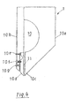
- the edge guide 2 has a contour which is described as follows:
- the height t 1 is constant. From point b downstream, the height gradually increases, reaching up to the peak c of height t 2 . From the high point c, the height gradually decreases and reaches the point d of
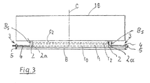
- the movable edge guides 2 can be adjusted in the transverse direction. This is in FIG. 2 and also in FIG. 3 clarified.
- FIG. 2 shows a view along the line A from FIG. 1 and FIG. 3 off along the B line FIG. 1 , The following description applies to both figures.
- the device for adjusting the position 3 consists of a bolt 4, which is rotatably mounted on the outside of the sliding edge guides 2 and a nut member 5, which is bolted to the respective bolt 4 and at the same time on the side edge Bs of the guide plate B is made firm.
- the discharge width of the application heads is set to correspond to the dimension between the inner surfaces 2a of the slidable edge guides 2.
- FIG. 4 shows a gun, which is generally designated here only with 1. The design meets equally for those from the FIG. 1 removable heads 1A, 1B and 1C too.
- a manifold 10 for the application medium extends in the transverse direction of the application head 1.
- the application head 1 is constructed so that a side part 10a, which contains the manifold 10 and a side part 10b, which is formed without a manifold 10, adjacent to each other.
- 11 is a slot which is connected to the manifold and directed downwards. It is formed between the lip on the fixed side 10c and the lip on the movable side 10d, which are arranged to each other.
- the opening width of the slot 11 is 0.3 to 0.5 mm.
- the lip on the movable side 10d is fixed to the lower end of the mold 10b with a plurality of bolts for adjusting the profile.
- the bolts for adjusting the profile are a set consisting of the upper pin 10e, the lower pin 10g and the middle pull pin 10f. They are at a distance of about 50 mm in the transverse direction of the Attached gun. By fine adjustment of the opening of the slot 11, the profile of the curtain can be adjusted exactly and vary.
- the application width can be adjusted in accordance with the width of the web w.
- the width of the opening of the slot 11 are simply not inserted at both edges of the slot 11 with drawn spacers from below. These spacers are then pressed down from the outside so as to prevent leakage. At the same time falling out of the spacers is prevented.
- a lid can be inserted from the side.
- the said lid may have a plastic tip. This is constructed so that it is liquid-tight and protrudes into the discharge slot.
- FIG. 5 shows possible positions of the guns and the drip pans from the state at startup or a paper tear to the normal state during operation. This figure is compared to the FIG. 1 the foremost down-facing gun 1D is added and explained in relation to a case where a total of three down-facing guns are used.
- FIG. 10 is a diagram for explaining that application medium is flowed at startup or a paper tear prior to each coating on the guns.
- the two downwardly directed applicator heads 1A, 1B which are located above the guide plate B, move in advance to the parked position (left-hand side, that is, downstream) as shown by a dash dotted line.
- the foremost down-facing gun 1D moves to the upstream side in the parking position (right side of image).
- the flowed application medium is collected in each arranged below collecting trays 40, 41 and 44 and used circulating again.
- the application medium flowing from the upward-facing application head 1C flows is discharged, as shown by the dashed line, along the guide plate B, then flows downwardly from the downwardly directed curtain guide Bb, is collected and circulated again by the sump 42 which is disposed thereunder.
- FIG. 5 (B) It is shown that the application heads 1A, 1B, 1C and 1D are in the operating position.
- the drip pan 41 is still in the collection position shown.
- the drip pan 40 moves a little to the right with its obliquely upwardly extending guide plate 40a. and thereby covers the sump 41. Therefore, the coating medium discharged from the downwardly directed applicator head 1A can be recirculated without mixing with the medium discharged from the downwardly directed applicator head 1B.
- the collecting trough 44 associated with the application head 1D remains in its previous position with its guide plate 44a.
- FIG. 5 (C) shows the state during normal operation, ie the operating position of the curtain heads.
- the drip pan 43 for the mixed curtain is pushed into parking position below the drip pan 42.
- the sump 43 may also be on the front side, as in FIG FIG. 5 (A) is shown.
- the 4-layer curtain V is now applied directly to the web w.
- Line w 1 shown with a long dashed dotted line indicates the course of the web w in the state where the web w is not coated.
- the down-facing guns are two or three pieces, but it may be just one gun or four guns or more.
- the guide plate B is fixed, but it may also be one in which the inclination angle of the slope Ba can be adjusted.
Landscapes
- Coating Apparatus (AREA)
- Paper (AREA)
Applications Claiming Priority (1)
| Application Number | Priority Date | Filing Date | Title |
|---|---|---|---|
| JP2008115460A JP5282284B2 (ja) | 2008-04-25 | 2008-04-25 | カーテンコータ |
Publications (1)
| Publication Number | Publication Date |
|---|---|
| EP2111925A1 true EP2111925A1 (de) | 2009-10-28 |
Family
ID=40823369
Family Applications (1)
| Application Number | Title | Priority Date | Filing Date |
|---|---|---|---|
| EP09157201A Withdrawn EP2111925A1 (de) | 2008-04-25 | 2009-04-02 | Vorhang-Auftragswerk |
Country Status (2)
| Country | Link |
|---|---|
| EP (1) | EP2111925A1 (ja) |
| JP (1) | JP5282284B2 (ja) |
Cited By (2)
| Publication number | Priority date | Publication date | Assignee | Title |
|---|---|---|---|---|
| WO2012163787A1 (de) * | 2011-05-30 | 2012-12-06 | Voith Patent Gmbh | Verfahren zur herstellung einer holzfreien gestrichenen oder leichtgewichtig gestrichenen papierbahn |
| EP2583760A4 (de) * | 2010-05-18 | 2017-12-20 | Voith Patent GmbH | Df-beschichterkopf |
Citations (3)
| Publication number | Priority date | Publication date | Assignee | Title |
|---|---|---|---|---|
| WO2006097376A1 (de) * | 2005-03-14 | 2006-09-21 | Voith Patent Gmbh | Auftragsvorrichtung |
| DE102006052687A1 (de) * | 2006-11-07 | 2008-05-08 | Voith Patent Gmbh | Verfahren zum mehrschichtigen Auftragen |
| WO2009000715A1 (de) | 2007-06-26 | 2008-12-31 | Voith Patent Gmbh | Auftragsverfahren sowie vorhangauftragswerk |
Family Cites Families (2)
| Publication number | Priority date | Publication date | Assignee | Title |
|---|---|---|---|---|
| DE3041721A1 (de) * | 1980-11-05 | 1982-06-09 | Agfa-Gevaert Ag, 5090 Leverkusen | Vorrichtung zum auftragen von mindestens einer schicht auf eine oberflaeche eines gutes |
| FI121242B (fi) * | 2004-02-25 | 2010-08-31 | Metso Paper Inc | Menetelmä ja järjestely paperi-/kartonkirainan päällystämiseksi verhopäällystyslaitteella |
-
2008
- 2008-04-25 JP JP2008115460A patent/JP5282284B2/ja not_active Expired - Fee Related
-
2009
- 2009-04-02 EP EP09157201A patent/EP2111925A1/de not_active Withdrawn
Patent Citations (3)
| Publication number | Priority date | Publication date | Assignee | Title |
|---|---|---|---|---|
| WO2006097376A1 (de) * | 2005-03-14 | 2006-09-21 | Voith Patent Gmbh | Auftragsvorrichtung |
| DE102006052687A1 (de) * | 2006-11-07 | 2008-05-08 | Voith Patent Gmbh | Verfahren zum mehrschichtigen Auftragen |
| WO2009000715A1 (de) | 2007-06-26 | 2008-12-31 | Voith Patent Gmbh | Auftragsverfahren sowie vorhangauftragswerk |
Cited By (2)
| Publication number | Priority date | Publication date | Assignee | Title |
|---|---|---|---|---|
| EP2583760A4 (de) * | 2010-05-18 | 2017-12-20 | Voith Patent GmbH | Df-beschichterkopf |
| WO2012163787A1 (de) * | 2011-05-30 | 2012-12-06 | Voith Patent Gmbh | Verfahren zur herstellung einer holzfreien gestrichenen oder leichtgewichtig gestrichenen papierbahn |
Also Published As
| Publication number | Publication date |
|---|---|
| JP2009262064A (ja) | 2009-11-12 |
| JP5282284B2 (ja) | 2013-09-04 |
Similar Documents
| Publication | Publication Date | Title |
|---|---|---|
| EP1861207B1 (de) | Auftragsvorrichtung | |
| WO2009000715A1 (de) | Auftragsverfahren sowie vorhangauftragswerk | |
| EP2146003A2 (de) | Vorhang-Auftragswerk | |
| EP0781885A1 (de) | Auftragswerk zum direkten oder indirekten Auftragen eines flüssigen oder pastösen Mediums auf eine laufende Materialbahn | |
| EP2396121A1 (de) | Vorhang-auftragswerk | |
| EP1544353A1 (de) | Vorhang-Auftragsvorrichtung | |
| EP2111925A1 (de) | Vorhang-Auftragswerk | |
| WO2001047643A1 (de) | Verfahren und vorrichtung zum beschichten einer laufenden materialbahn | |
| EP2379230A1 (de) | Vorhangauftragswerk | |
| EP1749585A2 (de) | Auftragsverfahren | |
| EP2067531A2 (de) | Randführung | |
| EP2014376A2 (de) | Vorhangstreichmaschine | |
| EP2017012A2 (de) | Vorhangstreichmaschine | |
| EP2198975B1 (de) | Vorhang-Auftragswerk | |
| EP2409781B1 (de) | Vorhangauftragswerk | |
| DE102007000776A1 (de) | Auftragsvorrichtung | |
| EP2070600B1 (de) | Verfahren zur Beschichtung einer laufenden Papier-, Karton- oder anderen Faserstoffbahn mittels Vorhangbeschichtung | |
| EP2172592B1 (de) | Vorhang-Auftragswerk | |
| DE102008040409A1 (de) | Vorhang-Auftragswerk | |
| EP2070599A2 (de) | Vorhang-Auftragswerk | |
| DE102007000775A1 (de) | Auftragsvorrichtung | |
| EP0849395A1 (de) | Auftragwerk zum direkten oder indirekten Auftragen eines flüssigen oder pastösen Streichmediums auf einer laufende Matrialbahn, insbesondere aus Papier onder Karton | |
| EP1947241A1 (de) | Vorhangstreichverfahren | |
| WO2004007091A1 (de) | Beschichtungskopf | |
| DE20321850U1 (de) | Auftragsvorrichtung |
Legal Events
| Date | Code | Title | Description |
|---|---|---|---|
| PUAI | Public reference made under article 153(3) epc to a published international application that has entered the european phase |
Free format text: ORIGINAL CODE: 0009012 |
|
| AK | Designated contracting states |
Kind code of ref document: A1 Designated state(s): AT BE BG CH CY CZ DE DK EE ES FI FR GB GR HR HU IE IS IT LI LT LU LV MC MK MT NL NO PL PT RO SE SI SK TR |
|
| 17P | Request for examination filed |
Effective date: 20100428 |
|
| 17Q | First examination report despatched |
Effective date: 20100624 |
|
| GRAP | Despatch of communication of intention to grant a patent |
Free format text: ORIGINAL CODE: EPIDOSNIGR1 |
|
| STAA | Information on the status of an ep patent application or granted ep patent |
Free format text: STATUS: THE APPLICATION IS DEEMED TO BE WITHDRAWN |
|
| 18D | Application deemed to be withdrawn |
Effective date: 20120915 |