EP2111771A1 - Schuh zum abrollenden Gehen - Google Patents
Schuh zum abrollenden Gehen Download PDFInfo
- Publication number
- EP2111771A1 EP2111771A1 EP08155035A EP08155035A EP2111771A1 EP 2111771 A1 EP2111771 A1 EP 2111771A1 EP 08155035 A EP08155035 A EP 08155035A EP 08155035 A EP08155035 A EP 08155035A EP 2111771 A1 EP2111771 A1 EP 2111771A1
- Authority
- EP
- European Patent Office
- Prior art keywords
- rolling element
- outsole
- shoe
- shoe according
- recess
- Prior art date
- Legal status (The legal status is an assumption and is not a legal conclusion. Google has not performed a legal analysis and makes no representation as to the accuracy of the status listed.)
- Withdrawn
Links
Images


Classifications
-
- A—HUMAN NECESSITIES
- A43—FOOTWEAR
- A43B—CHARACTERISTIC FEATURES OF FOOTWEAR; PARTS OF FOOTWEAR
- A43B13/00—Soles; Sole-and-heel integral units
- A43B13/14—Soles; Sole-and-heel integral units characterised by the constructive form
- A43B13/143—Soles; Sole-and-heel integral units characterised by the constructive form provided with wedged, concave or convex end portions, e.g. for improving roll-off of the foot
- A43B13/145—Convex portions, e.g. with a bump or projection, e.g. 'Masai' type shoes
-
- A—HUMAN NECESSITIES
- A43—FOOTWEAR
- A43B—CHARACTERISTIC FEATURES OF FOOTWEAR; PARTS OF FOOTWEAR
- A43B13/00—Soles; Sole-and-heel integral units
- A43B13/02—Soles; Sole-and-heel integral units characterised by the material
- A43B13/026—Composites, e.g. carbon fibre or aramid fibre; the sole, one or more sole layers or sole part being made of a composite
-
- A—HUMAN NECESSITIES
- A43—FOOTWEAR
- A43B—CHARACTERISTIC FEATURES OF FOOTWEAR; PARTS OF FOOTWEAR
- A43B13/00—Soles; Sole-and-heel integral units
- A43B13/02—Soles; Sole-and-heel integral units characterised by the material
- A43B13/12—Soles with several layers of different materials
-
- A—HUMAN NECESSITIES
- A43—FOOTWEAR
- A43B—CHARACTERISTIC FEATURES OF FOOTWEAR; PARTS OF FOOTWEAR
- A43B13/00—Soles; Sole-and-heel integral units
- A43B13/14—Soles; Sole-and-heel integral units characterised by the constructive form
- A43B13/16—Pieced soles
-
- A—HUMAN NECESSITIES
- A43—FOOTWEAR
- A43B—CHARACTERISTIC FEATURES OF FOOTWEAR; PARTS OF FOOTWEAR
- A43B13/00—Soles; Sole-and-heel integral units
- A43B13/14—Soles; Sole-and-heel integral units characterised by the constructive form
- A43B13/18—Resilient soles
- A43B13/187—Resiliency achieved by the features of the material, e.g. foam, non liquid materials
- A43B13/188—Differential cushioning regions
-
- A—HUMAN NECESSITIES
- A43—FOOTWEAR
- A43B—CHARACTERISTIC FEATURES OF FOOTWEAR; PARTS OF FOOTWEAR
- A43B7/00—Footwear with health or hygienic arrangements
- A43B7/14—Footwear with health or hygienic arrangements with foot-supporting parts
- A43B7/1405—Footwear with health or hygienic arrangements with foot-supporting parts with pads or holes on one or more locations, or having an anatomical or curved form
- A43B7/1415—Footwear with health or hygienic arrangements with foot-supporting parts with pads or holes on one or more locations, or having an anatomical or curved form characterised by the location under the foot
- A43B7/142—Footwear with health or hygienic arrangements with foot-supporting parts with pads or holes on one or more locations, or having an anatomical or curved form characterised by the location under the foot situated under the medial arch, i.e. under the navicular or cuneiform bones
-
- A—HUMAN NECESSITIES
- A43—FOOTWEAR
- A43B—CHARACTERISTIC FEATURES OF FOOTWEAR; PARTS OF FOOTWEAR
- A43B7/00—Footwear with health or hygienic arrangements
- A43B7/14—Footwear with health or hygienic arrangements with foot-supporting parts
- A43B7/1405—Footwear with health or hygienic arrangements with foot-supporting parts with pads or holes on one or more locations, or having an anatomical or curved form
- A43B7/1415—Footwear with health or hygienic arrangements with foot-supporting parts with pads or holes on one or more locations, or having an anatomical or curved form characterised by the location under the foot
- A43B7/143—Footwear with health or hygienic arrangements with foot-supporting parts with pads or holes on one or more locations, or having an anatomical or curved form characterised by the location under the foot situated under the lateral arch, i.e. the cuboid bone
Definitions
- the present invention relates to a shoe for a so-called rolling walk according to the preamble of claim 1, i. a walking shoe in which the outsole is structured in the bottom of the shoe.
- the “rolling off” was the Massais, an ethnic group in Kenya, apart, which move barefoot with a particularly healthy pace. Footwear that allow this particular walking even with shoes, are the subject of an invention, for example, in the document WO 01/15560 A1 ( PCT / CH00 / 00412 ) is described in detail. Further information about rolling, especially in the field of orthopedics, can be found in the special edition MBT, Orthomannchuhtechnik 12/2004, p. 22-28. MBT is the abbreviation for Masai Barefoot Technology (or Masai Barefoot Technology).
- the MBT shoes are characterized in particular by their external shape and the nature of the lower sole, ie the outsole. It will be up here Fig. 8 the drawing referenced, which is essentially the Fig. 1 in the above-mentioned document WO 01/15560 equivalent.
- reference numeral 2 refers to the top of the shoe.
- This upper part 2 is connected to an outsole 12 via a solid and hard but elastic midsole (insole) 10 (having a bottom 11).
- the outsole 12 which has a thickness between 0.5 and 5 cm, is arcuately curved in the side view and is soft and elastic.
- the lower surface of the outsole 12 is covered with a hard and also elastic sole bottom 13, which forms the actual running surface of the shoe.
- the midsole bottom 11 and the outsole bottom 13 have any spherical, arc or circular segment-like shape.
- the present invention has set itself the goal of maintaining the advantages of rolling walking while overcoming the disadvantages described above.
- the shoe to be created externally as little as possible from normal shoes.
- the rolling go is laid inside the shoe.
- the inventive shoe is defined in the characterizing part of claim 1. Particular or preferred embodiments form the subject of dependent claims.
- Japanese published patent application JP-A-1 0-2004-0028899 an insole with a recess in the midfoot and heel area of the shoe, in which a hollow spring body is inserted, inside which there is a spring element in the form of a leg spring.
- EP-0 497 152 is described a damping element which is mounted in the heel area of shoes, in particular safety shoes, for the purpose of damping the heel pressure, for example as part of an insole.
- the US patent application 2008/005929 describes, for example, a shock-absorbing sole with one or more gas-filled compartments, which give a spring action, and a damper, which according to a particular embodiment of a viscoelastic material is made.
- the present invention proposes to introduce at least one rolling element into the outsole of a shoe.
- the rolling element can be inserted into a form-fitting recess of the outsole, or the outsole can be formed so that it contains integrated this rolling element.
- the rolling element extends at least over part of the width of the shoe and is made of an at least partially elastic material, for example of an elastomer such as rubber or a polyurethane.
- the material of the rolling element harder than the material of the outsole.
- the hardness ratio of the two materials can be chosen arbitrarily and adjusted as needed. In this way it is ensured that the shoe behaves while walking according to the known principle, so that the rolling process runs in a natural way. In addition, the unwinding is favored in this way.
- the rolling element extends over the entire width of the outsole. Thanks to a continuous unrolling of the rolling element over the entire width of the shoe even greater stability, as well as a uniform loading of the outsole material can be ensured
- the inserted rolling element can have different shapes.
- the simplest form is that of a cylinder section, which may be a cylinder of circular or oval cross-section.
- This cylinder portion may be made of solid material or hollow, but the cavity may also be filled with an elastic material.
- the sole it is also conceivable to design the sole so that the inserted rolling element is visible from the outside.
- the sole may be formed to form a continuous hole (through a portion of the sole, the rolling element and the second portion of the sole).
- the rolling element can also be adapted to the different shape of the right and left shoe.
- the rolling element has the shape of a truncated cone section with a circular or oval cross-section.
- the variants described above can be used.
- the rolling element described has a flat and a curved surface. It is possible to make both surfaces curved. This allows the element to better adapt to the sole of the foot.
- the radii of curvature of both surfaces can be either the same or different.
- the MBT shoe 1 is in the document PCT / CH00 / 00412 referred to as "active rolling device". It consists of the upper part 2 and the composite lower part 10 to 13.
- 10 represents the actual insole, which is also referred to as a midsole. This is firm, hard and elastic.
- Underneath is a midsole bottom 11 which separates the midsole 10 from the insole 12, which is soft and elastic.
- the sole bottom 13 provides contact with the surface on which the user is walking.
- a shoe 10 according to the invention is shown in a perspective view and transparent.
- a top 20 also called an upper shoe
- the upper part 20 is connected to the bottom 30 in the usual manner known to those skilled in the art.
- the ankle part of the upper part is provided with a narrow padding 25. Since it is an open shoe, a lace 22 is provided.
- other fasteners may be used, such as a velcro closure or other similar means.
- the outsole 33 which forms a part of the bottom 30 and which consists of a little compressible, hard and elastic material, small transverse ribs 32 are attached below, whereby this sole receives non-slip properties.
- the rear portion of the bottom terminates in a heel portion 33; when the shoe is drawn, the outsole is continuous without a specially shaped heel; such a continuous sole improves the running properties.
- the upper part 20 of the shoe can be made of leather, fabric or plastic as desired and have any hardness.
- the closure as described above, for example, be constructed on a lacing or Velcro version.
- a rolling element 40 is inserted in a recess of the bottom 30, and in the free, upwardly directed surface.
- This rolling element has like the recess in the shape of a cylindrical portion and at least partially made of an elastic material.
- it may be a soft material.
- this roll-off element 40 may be made of the same material as the bottom 30.
- the rolling element 40 is smooth and flat on its upper surface and sets as shown Fig. 2 indicates the heel area 35 "in a smooth transition towards the toe area 35 'of the floor away.
- a rolling element according to the invention is intended for a right shoe; as in the rolling element 40 of the Fig. 1
- the lower surface 42 is curved with the same radius of curvature as the recess in the bottom 30, and the upper surface 41 is flat.
- the left shoe roll-off member 40 is the mirror image of the right shoe roll-off member just described. It should be mentioned here that this particular form of the rolling element 40 corresponds to the physiological characteristics of human walking, since the foot does not roll on the ground completely parallel to the direction of walking.
- both the leading edge 44B 'and the trailing edge 44B are at an angle to the side edges of the element, which are normally parallel but may also be at an angle to each other Fig. 3B also has a strong curvature of the bottom 42.
- leading edges and trailing edges i.e., at a certain angle to the side edges of the rolling element 40
- Such a course of the leading edges and trailing edges is, of course, also possible and conceivable in all other described embodiments of the rolling element 40.
- the rolling element 40 which in Fig. 3C is shown has the outer shape of the rolling element 40 in Fig. 3A , with the modification that it has a cavity 43.
- the top of the element is again denoted by 41 and its curved bottom by 42.
- the two arrows symbolize an open passage.
- the area of the shoe bottom 30, whose walls are opposite the cavity 43 can also be left open so that an air circulation in the direction of the two arrows (and also in the opposite direction) can form during walking. It also creates an aesthetic effect.
- the rolling element 40 With the opening 43 shown, the rolling element 40 becomes more elastic.
- the wall thicknesses are chosen depending on the physical properties of the material to withstand the stresses of use can withstand. It is possible, if necessary, insert one or more spring elements (not shown) in the cavity 43.
- FIG Fig. 4A A further embodiment of the inventive rolling element 40 is shown in FIG Fig. 4A shown.
- the upper surface 41 is curved convex, while the lower surface 42 is flat or only slightly curved.
- This rolling element gives a particularly pronounced support of the sole of the foot while walking.
- the rolling element according to Fig. 4B differs from the rolling element 40 in Fig. 4A in that the upper surface 41 is slightly convex and the lower surface 42 is more convexly curved. With 43 each of the viewer facing side surface of the rolling element is designated.
- Fig. 5 the disassembled structure of a shoe bottom 30 according to the invention is shown schematically in a perspective view.
- a midsole 50 which is relatively thin and has a shape that adapts to the shape of the areas 35 ', 36 and 35 "of the outsole 33, ie with a flat or slightly curved bale and toe area 55 ', a curved middle area 56 and a flat or slightly curved heel area 55 "on this midsole 50 is now the actual insole, ie the upper sole 41, placed on the underside of the upper sole 41 a thickening 43.
- the shape of the underside of the upper sole 41 is precisely adapted to the shape of the midsole 50.
- the underside 42 of the thickening nestles 43 to the recess 36 of the outsole 33 with the interposition of the sole 50 at.
- the upper sole 41 represents the actual rolling element 40.
- FIG. 5 illustrates another embodiment of the invention.
- a block-shaped rolling element 40 having a slightly concave upper surface 41, a flat rear surface 44 "extending downwardly at approximately right angles from the upper surface 41, and a lower surface 42 in FIG a corresponding recess of the bottom 30.
- the lower surface 42 of the rolling element 40 extends from the lower edge of the rear surface 44 "forward, then rises and then in the area of the toe area 35 'in the upper surface 41 on, with an edge 44 'arises.
- the block has the shape of a wedge, the broad back side of which faces the heel region 35 "of the shoe.”
- 43 a side surface of the block and wedge rolling element 40 and 32 indicate the lugs at the bottom of the shoe bottom.
- FIG. 7 another embodiment of the shoe according to the invention is shown perspectively in longitudinal section.
- the entire outsole 33 of the shoe is formed as a compressible, elastic block in which a rolling element 40 is located, which in this case the shape of the element 40 according to Fig. 4B having.
Abstract
Es wird ein Schuh (10) zum abrollenden Gehen beschrieben, in dessen Laufsohle (33) sich ein Abrollelement (40) befindet, welches sich über einen Teil der Länge und über mindestens einen Teil der Breite der Laufsohle (33) erstreckt, mindestens in demjenigen Bereich der Laufsohle (33) angeordnet ist, welcher dem Fussgewölbe gegenüberliegt, und aus einem mindestens teilweise elastischen Material besteht. Dieser Schuh bietet die Vorteile des bekannten MBT-Schuhs, besitzt aber einen anderen Aufbau und unterscheidet sich optisch nicht von den bekannten Schuhen, beispielsweise den Basket-Schuhen.
Description
- Die vorliegende Erfindung betrifft einen Schuh für ein sogenanntes abrollendes Gehen nach dem Oberbegriff des Patentanspruches 1, d.h. einen Schuh zum abrollenden Gehen bei dem die Laufsohle im Boden des Schuhs strukturiert ist.
- Das "abrollende Gehen" wurde den Massais, einer ethnischen Gruppe in Kenia, abgesehen, welche sich barfuss mit einer besonders gesunden Gangart bewegen. Fussbekleidungen, die dieses besondere Gehen auch mit Schuhen gestatten, sind Gegenstand einer Erfindung, die beispielsweise im Dokument
WO 01/15560 A1 PCT/CH00/00412 - Die Grundlagen des abrollenden Gehens sind im erwähnten Dokument beschrieben, dessen Inhalt durch Bezugnahme Bestandteil der vorliegenden Patentanmeldung sein soll. Daher soll auch dieses abrollende Gehen und dessen positive Auswirkungen auf den menschlichen Organismus, insbesondere seine Gehwerkzeuge, die Wirbelsäule und die Gelenke an dieser Stelle nicht beschrieben werden.
- Die MBT-Schuhe zeichnen sich insbesondere durch ihre äussere Form und die Beschaffenheit der Untersohle, d.h. der Laufsohle aus. Es wird hier auf
Fig. 8 der Zeichnung verwiesen, welche im Wesentlichen derFig. 1 im oben erwähnten DokumentWO 01/15560 - Die Verwendung solcher Schuhe beim Gehen beeinflusst, wie gesagt, die Gesundheit des Benutzers auf vorteilhafte Weise. Allerdings haben MBT-Schuhe auch viele Nachteile, welche ihrer Verbreitung auf dem Markt entgegen wirken.
- Als Erstes ist bekannt und auch beschrieben, dass die Verwendung der Schuhe zunächst eine mindestens sechswöchige Trainingszeit erfordert, während derer das Gehen, vor allem in den ersten Tagen, mühsam und sogar nicht ganz ungefährlich ist. Zweitens haben diese Schuhe ein relativ wenig ansprechendes Erscheinungsbild, und dies hält die meisten Interessenten, insbesondere die Damen, vom Kauf und dem Tragen solcher Schuhe ab. Weiterhin ist auch nach Absolvierung der Gewöhnungsphase festzustellen, dass das Gehen mehr oder weniger instabil ist, insbesondere auf harten Böden.
- Als weiterer Nachteil ist anzumerken, dass die Laufsohle schnell abgenutzt wird, weil sie dünn sein muss, damit die Untersohle beim Gehen verformbar bleibt. Eine Reparatur einer abgelaufenen oder gerissenen Laufsohle ist oft nur schwer möglich, so dass dann das ganze, naturgemäss teure Schuhpaar ersetzt werden muss. Nicht zuletzt können solche Schuhe auf Grund der besonderen Sohlenform schwierig gestapelt werden, so dass sie beim Verstauen viel mehr Raum als herkömmliche Schuhe benötigen.
- Die vorliegende Erfindung hat sich zum Ziel gesetzt, die Vorteile des abrollenden Gehens beizubehalten und gleichzeitig die oben geschilderten Nachteile zu überwinden. Dabei soll sich der zu schaffende Schuh äusserlich so wenig wie möglich von normalen Schuhen unterscheiden.
- Erfindungsgemäss wird das abrollende Gehen ins Innere des Schuhs verlegt. Der erfindungsgemässe Schuh ist im kennzeichnenden Teil des Patentanspruches 1 definiert. Besondere oder bevorzugte Ausführungsformen bilden den Gegenstand von abhängigen Ansprüchen.
- Es ist bereits bekannt, in die Laufsohle eines Schuhs Einlagen einzusetzen oder auf der Laufsohle anzuordnen, und es sind schon zahlreiche Einlegesohlen und Einlegeelemente für Schuhe beschrieben worden. Die im Stand der Technik bekannten Einlagen bzw. Einlageelemente haben aber sämtlich den Zweck, dämpfend, deodorierend oder desinfizierend zu wirken oder die Form des Schuhs an den Fuss anzupassen und können ein abrollendes Gehen weder beschreiben noch nahelegen.
- Beispielsweise beschreibt die japanische veröffentlichte Patentanmeldung
JP-A-1 0-2004-0028899 - Gemäss der japanischen Patentpublikation
JP-2004-166989 - In der europäischen Patentanmeldung
EP-0 497 152 ist ein Dämpfungselement beschrieben, das im Fersenbereich von Schuhen, insbesondere Sicherheitsschuhen, zwecks Dämpfung des Fersendrucks angebracht ist, beispielsweise als Bestandteil einer Einlegesohle. - Die US-amerikanische Patentanmeldung
2008/005929 beschreibt zum Beispiel eine stossgedämpfte Sohle mit einem oder mehreren gasgefüllten Abteilen, welche eine Federwirkung ergeben, und einen Dämpfer, welcher gemäss einer besonderen Ausführungsform aus einem viskoelastischen Material angefertigt wird. - Demgegenüber schlägt die vorliegende Erfindung vor, in die Laufsohle eines Schuhs mindestens ein Abrollelement einzubringen. Dabei kann das Abrollelement in eine formschlüssig ausgebildete Ausnehmung der Laufsohle eingelegt werden, oder die Laufsohle kann so ausgebildet werden, dass sie dieses Abrollelement integriert enthält. Das Abrollelement erstreckt sich dabei mindestens über einen Teil der Breite des Schuhs und ist aus einem mindestens teilweise elastischen Material gefertigt, beispielsweise aus einem Elastomer wie Kautschuk oder einem Polyurethan.
- Vorteilhaft ist 2. das Material des Abrollelements härter als das Material der Laufsohle. Das Härteverhältnis der beiden Materialien kann beliebig gewählt und nach Bedarf angepasst werden. Auf diese Weise wird gewährleistet, dass sich der Schuh beim Gehen nach dem bekannten Prinzip verhält, so dass der Abrollprozess auf eine natürliche Weise abläuft. Ausserdem wird auf diese Weise das Abrollen begünstigt.
- In einer besonderen Ausführungsvariante erstreckt sich das Abrollelement über die gesamte Breite der Laufsohle. Dank einer durchgehenden Abrollung des Abrollelements über die gesamte Breite des Schuhs kann eine noch grössere Stabilität, sowie ein gleichmässiges Beanspruchen des Laufsohlenmaterials gewährleistet werden
- Das eingelegte Abrollelement kann unterschiedliche Formen aufweisen. Die einfachste Form ist diejenige eines Zylinderabschnitts, wobei es sich um einen Zylinder mit kreisförmigem oder ovalem Querschnitt handeln kann. Dieser Zylinderabschnitt kann aus Vollmaterial bestehen oder aber auch hohl sein, wobei der Hohlraum auch mit einem elastischen Material ausgefüllt sein kann. Auch ist es denkbar, die Sohle so auszubilden, dass das eingelegte Abrollelement von aussen sichtbar ist. Wenn ein hohles Abrollelement verwendet wird, kann die Sohle insbesondere auch so ausgebildet werden, dass dabei ein durchgehendes Loch (durch einen Abschnitt der Sohle, das Abrollelement und den zweiten Abschnitt der Sohle) gebildet werden.
- Das Abrollelement kann auch an die unterschiedliche Form des rechten und linken Schuhs angepasst werden. Zu diesem Zweck hat dann das Abrollelement die Form eines Kegelstumpfabschnitts mit kreisförmigem oder ovalem Querschnitt. Im Übrigen können die oben beschriebenen Varianten benutzt werden.
- Das beschriebene Abrollelement weist eine ebene und eine gekrümmte Oberfläche auf. Es ist möglich, beide Flächen gekrümmt auszuführen. Dadurch kann sich das Element besser an die Fusssohle anpassen. Die Krümmungsradien beider Flächen können dabei entweder gleich oder auch verschieden sein.
- Weitere Einzelheiten der Erfindung gehen aus der nun folgenden Beschreibung besonderer bzw. bevorzugter Ausführungsformen hervor, die in der beigegebenen Zeichnung dargestellt sind. Der Beschreibung lassen sich auch die Vorteile der Erfindung entnehmen sowie Anregungen, wie der Erfindungsgegenstand im Rahmen des Beanspruchten abgeändert oder auch weiter entwickelt werden kann.
- In der Zeichnung stellen dar:
-
Fig. 1 eine perspektivische Ansicht eines erfindungsgemässen Schuhs seitlich von oben, wobei das Innere zu sehen ist, -
Fig. 2 eine perspektivische Ansicht des Bodens eines erfindungsgemässen Schuhs seitlich von oben, -
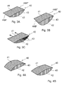
Fig. 3A bis 3C perspektivische Ansichten verschiedener Formen der Abrollelemente, -
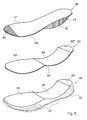
Fig. 4A und 4B perspektivische Ansichten weiterer Abrollelemente, -
Fig. 5 die Zusammenstellung eines Bodens eines erfindungsgemässen Schuhs, ebenfalls in perspektivischer Darstellung, -
Fig. 6 eine andere Ausführungsform des erfindungsgemässen Schuhs in perspektivischer Darstellung, -
Fig. 7 eine weitere Ausführungsform des erfindungsgemässen Schuhs in perspektivischer Darstellung, und -
Fig. 8 eine schematische Seitenansicht eines MBT-Schuhs gemäss dem Stand der Technik. - Es soll zuerst kurz auf den Schuh eingegangen werden, der die Idee für die vorliegende Erfindung abgegeben hat, der MBT-Schuh, der in schematischer Form als Seitenansicht in
Fig. 8 dargestellt ist. - Der MBT-Schuh 1 ist im Dokument
PCT/CH00/00412 - In
Fig. 1 ist ein erfindungsgemässer Schuh 10 in perspektivischer Darstellung sowie durchsichtig gezeichnet. Wie die meisten normalen Schuhe ist ein Oberteil 20 (auch Oberschuh genannt) mit einer vorderen Kappe 21 und einem Fersenteil 24 sowie Seitenteilen 23 vorhanden. Das Oberteil 20 ist mit dem Boden 30 auf übliche, dem Fachmann bekannte Weise verbunden. Die Knöchelpartie des Oberteils ist mit einer schmalen Polsterung 25 versehen. Da es sich um einen offenen Schuh handelt, ist ein Schnürriemen 22 vorgesehen. Alternativ können anstelle des Schnürriemes 22 auch andere Befestigungsmittel verwendet werden, wie beispielsweise ein Velcro-Verschluss oder andere ähnliche Mittel. An der Laufsohle 33, welche einen Teil des Bodens 30 bildet und die aus einem wenig kompressiblen, harten und elastischen Material besteht, sind unten kleine Querstollen 32 angebracht, wodurch diese Sohle rutschfeste Eigenschaften erhält. Der hintere Bereich des Bodens endet in einem Absatzteil 33; beim gezeichneten Schuh ist die Laufsohle durchgehend ohne einen besonders angeformten Absatz; eine solche durchgehende Sohle verbessert die Laufeigenschaften. Das Oberteil 20 des Schuhs kann nach Wunsch aus Leder, Stoff oder Kunststoff bestehen und eine beliebige Härte aufweisen. Der Verschluss kann, wie oben beschrieben, beispielsweise auf einer Schnürungs- oder Velcro-Version aufgebaut sein. - In eine Ausnehmung des Bodens 30, und zwar und in der freien, nach oben gerichteten Oberfläche, ist ein Abrollelement 40 eingelegt. Dieses Abrollelement besitzt wie die Ausnehmung die Form eines Zylinderabschnitts und besteht mindestens teilweise aus einem elastischen Material. Vorteilhaft kann es sich um ein weiches Material handeln. Grundsätzlich kann dieses Abrollelement 40 aus demselben Material bestehen wie der Boden 30. Es ist in diesem Zusammenhang aber sehr wichtig, dass das Abrollelement 40 einen etwas härteren Durometer aufweist als der Boden 30 (d.h. als der Mittelsohlenabschnitt, in oder auf welchem das Abrollelement 40 positioniert ist), so dass bei Druckbelastung des Schuhs 10 zunächst eine Kompression des Mittelsohlenabschnitts und erst dann eine Kompression des Abrollelements 40 einsetzt. Das Abrollelement 40 ist auf seiner oberen Fläche glatt und eben und setzt, wie aus
Fig. 2 hervorgeht, den Absatzbereich 35" in glattem Übergang in Richtung des Zehenbereichs 35' des Bodens fort. - In den
Fig. 3A bis 3C sind drei verschiedene Formen eines erfindungsgemässen Abrollelements dargestellt. Das Element 40 gemässFig. 3A ist für einen rechten Schuh vorgesehen; wie im Abrollelement 40 derFig. 1 ist die untere Fläche 42 gekrümmt, und zwar mit dem gleichen Krümmungsradius wie die Ausnehmung im Boden 30, und die obere Fläche 41 ist eben. Die Vorderkante 44A' erstreckt sich rechtwinklig zu den Seitenkanten des Elements 40, aber die Hinterkante 44A" verläuft zu diesen Seitenkanten schräg, wobei die in der Figur oben links dargestellte Seitenkante kürzer ist als die Seitenkante unten rechts. Damit bilden die vier geraden Kanten der ebenen Oberfläche des Elements ein Trapez. Diese Form wurde gewählt, weil der nach innen gerichtete Mittelbereich eines Fusses "eingezogen" ist und besserer Unterstützung bedarf. Bei dieser Ausführungsform ist das Abrollelement 40 für den linken Schuh des Schuhpaares das Spiegelbild des eben beschriebenen Abrollelements für den rechten Schuh. Es soll hier noch erwähnt werden, dass diese besondere Form des Abrollelements 40 den physiologischen Besonderheiten des menschlichen Gehens entspricht, da der Fuss auf dem Boden nicht vollkommen parallel zur Gehrichtung abrollt. - Diese Verhältnisse sind beim Abrollelement 40 gemäss
Fig. 3B noch verstärkt. Hier verlaufen sowohl die Vorderkante 44B' als auch die Hinterkante 44B" in einem Winkel zu den Seitenkanten des Elements, die normalerweise Parallelen sind, aber ebenfalls einen Winkel zueinander einschliessen können. Das Element 40 vonFig. 3B weist zudem eine stärke Krümmung der Unterseite 42 auf. - Ein solcher Verlauf der Vorderkanten und Hinterkanten (d.h. unter einem gewissen Winkel zu den Seitenkanten des Abrollelements 40) ist selbstverständlich auch bei allen anderen beschriebenen Ausführungsformen des Abrollelements 40 möglich und denkbar.
- Das Abrollelement 40, welches in
Fig. 3C gezeigt ist, hat die äussere Form des Abrollelements 40 inFig. 3A , mit der Abänderung, dass es einen Hohlraum 43 aufweist. Die Oberseite des Elements ist wieder mit 41 und seine gekrümmte Unterseite mit 42 bezeichnet. Die beiden Pfeile symbolisieren einen offenen Durchgang. Mit diesem Abrollelement kann der Bereich des Schuhbodens 30, dessen Wände dem Hohlraum 43 gegenüberliegen, auch offen gelassen werden, so dass sich beim Gehen eine Luftzirkulation in Richtung der beiden Pfeile (und auch in Gegenrichtung) ausbilden kann. Auch entsteht dadurch ein ästhetischer Effekt. - Mit der gezeigten Öffnung 43 wird das Abrollelement 40 elastischer. Die Wandstärken werden in Abhängigkeit von den physikalischen Eigenschaften des Materials so gewählt, dass sie den Beanspruchungen beim Gebrauch standhalten können. Es ist möglich, im Bedarfsfalle ein oder mehrere Federelemente (nicht gezeichnet) in den Hohlraum 43 einzulegen.
- Eine weitere Ausführungsform des erfindungsgemässen Abrollelements 40 ist in
Fig. 4A dargestellt. Hier ist die obere Fläche 41 konvex gekrümmt, während die untere Fläche 42 eben oder nur leicht gekrümmt ist. Dieses Abrollelement ergibt beim Gehen eine besonders ausgeprägte Stützung der Fusssohle. - Das Abrollelement gemäss
Fig. 4B unterscheidet sich vom Abrollelement 40 inFig. 4A dadurch, dass die obere Fläche 41 leicht und die untere Fläche 42 stärker konvex gekrümmt sind. Mit 43 ist jeweils die dem Betrachter zugewandte Seitenfläche des Abrollelements bezeichnet. - In
Fig. 5 ist der auseinander genommene Aufbau eines Schuhbodens 30 gemäss der Erfindung schematisch in perspektivischer Darstellung gezeigt. Der Boden 30 mit der Laufsohle 33, die unten mit Stollen 32 belegt ist, weist im mittleren Bereich, welcher dem Längsgewölbe des menschlichen Fusses gegenüberliegt, eine abgerundete Ausnehmung 36 auf, während der vordere Ballen- und Zehenbereich 35' und der Fersenbereich 35" eben oder nur ganz leicht konkav gekrümmt ausgeführt sind. Auf dieser Laufsohle 33 liegt nun eine Zwischensohle 50, die relativ dünn ist und eine Form hat, die sich an die Form der Bereiche 35', 36 und 35" der Laufsohle 33 anpasst, d.h. mit einem ebenen oder leicht gekrümmten Ballen- und Zehenbereich 55', einem gekrümmten mittleren Bereich 56 und einem ebenen oder leicht gekrümmten Fersenbereich 55". Auf diese Zwischensohle 50 wird nun die eigentliche Nutzsohle, d.h. die Obersohle 41, aufgelegt. An der Unterseite der Obersohle 41 ist eine Verdickung 43 vorgesehen. Die Form der Unterseite der Obersohle 41 ist der Form der Zwischensohle 50 genau angepasst. Dadurch schmiegt sich die Unterseite 42 der Verdickung 43 an die Ausnehmung 36 der Laufsohle 33 unter Zwischenlage der Sohle 50 an. Bei dieser Ausführungsform des erfindungsgemässen Schuhs stellt die Obersohle 41 das eigentliche Abrollelement 40 dar. - Die
Fig. 6 stellt eine weitere Ausführungsform der Erfindung dar. Hier ist ein blockförmiges Abrollelement 40 mit einer leicht konkav gekrümmten oberen Fläche 41, einer ebenen Hinterfläche 44", die sich ungefähr im rechten Winkel von der oberen Fläche 41 nach unten erstreckt, und einer unteren Fläche 42 in eine entsprechende Ausnehmung des Bodens 30 eingesetzt. Die untere Fläche 42 des Abrollelements 40 erstreckt sich dabei von der unteren Kante der Hinterfläche 44" nach vorn, steigt an und geht dann im Gebiet des Zehenbereichs 35' in die obere Fläche 41 über, wobei eine Kante 44' entsteht. Dadurch hat der Block die Form eines Keils, dessen breite Hinterseite gegen den Fersenbereich 35" des Schuhs zeigt. In der Figur bedeuten wiederum 43 eine Seitenfläche des block- und keilförmigen Abrollelements 40 und 32 die Stollen an der Unterseite des Schuhbodens. - In
Fig. 7 ist schliesslich noch eine andere Ausführungsform des erfindungsgemässen Schuhs im Längsschnitt perspektivisch dargestellt. Hier ist die gesamte Laufsohle 33 des Schuhs als kompressibler, elastischer Block geformt, in dem sich ein Abrollelement 40 befindet, welches in diesem Fall die Form des Elements 40 gemässFig. 4B aufweist. - Die dargestellten und besprochenen Ausführungsformen sind lediglich Beispiele, welche die Erfindung erläutern sollen. Die Erfindung ist nicht auf die Merkmale dieser Beispiele beschränkt und kann im Rahmen des Beanspruchten verändert, vereinfacht, ergänzt und weiterentwickelt werden.
Claims (12)
- Schuh (10) zum abrollenden Gehen, bei dem die Laufsohle (33) im Boden (30) des Schuhs strukturiert ist, dadurch gekennzeichnet, dass
sich in der Laufsohle (33) ein Abrollelement (40) befindet,
welches sich über einen Teil der Länge und mindestens über einen Teil der Breite der Laufsohle (33) erstreckt,
mindestens in demjenigen Bereich der Laufsohle (33) angeordnet ist, welcher dem Fussgewölbe gegenüberliegt, und
aus einem mindestens teilweise elastischen Material besteht. - Schuh nach Anspruch 1, dadurch gekennzeichnet, dass das Material des Abrollelements (40) härter als das Material der Laufsohle (33) ist.
- Schuh nach Anspruch 1 oder 2, dadurch gekennzeichnet, dass das Abrollelement (40) in eine Ausnehmung der oberen, freien Fläche der Laufsohle (33) eingesetzt ist, eine ebene obere Fläche (41) und eine konvex gekrümmte untere Fläche (42) aufweist und die Form eines Zylinderabschnitts aufweist
- Schuh nach Anspruch 1 oder 2, dadurch gekennzeichnet, dass das Abrollelement (40) in eine Ausnehmung der oberen, freien Fläche der Laufsohle (33) eingesetzt ist und eine ebene obere Fläche (41) in Form eines Rechtecks aufweist.
- Schuh nach Anspruch 1 oder 2, dadurch gekennzeichnet, dass das Abrollelement (40) in eine Ausnehmung der oberen, freien Fläche der Laufsohle (33) eingesetzt ist und die obere Fläche des Abrollelements (40) die Form eines unregelmässigen Trapezes aufweist, wobei das Abrollelement (40) für einen Schuh eines Paares das Spiegelbild für den anderen Schuh des Paares ist.
- Schuh nach Anspruch 1 oder 2, dadurch gekennzeichnet, dass das Abrollelement (40) in eine Ausnehmung der oberen, freien Fläche der Laufsohle (33) eingesetzt ist und einen Hohlraum (43) aufweist (Fig. 3C).
- Schuh nach Anspruch 1 oder 2, dadurch gekennzeichnet, dass das Abrollelement (40) in eine Ausnehmung der oberen, freien Fläche der Laufsohle eingesetzt und auf der Oberseite (41) konvex gekrümmt ist.
- Schuh nach Anspruch 1 oder 2, dadurch gekennzeichnet, dass das Abrollelement (40) in eine Ausnehmung der oberen, freien Fläche der Laufsohle (33) eingesetzt und sowohl auf der Oberseite (41) als auch auf der Unterseite (42) konvex gekrümmt ist, wobei die beiden Krümmungsradien verschieden oder gleich sind.
- Schuh nach Anspruch 1 oder 2, dadurch gekennzeichnet, dass das Abrollelement (40) im Inneren der Laufsohle (33) angeordnet ist.
- Schuh nach Anspruch 1 oder 2, dadurch gekennzeichnet, dass das Abrollelement (40) in eine Ausnehmung der oberen, freien Fläche der Laufsohle (33) eingesetzt ist und die Form eines keilartigen Blocks aufweist, der sich über den Zehen- und Gewölbebereich des Fusses erstreckt und dessen breite Endfläche (44") nach hinten weist.
- Schuh nach einem der vorstehenden Ansprüche, dadurch gekennzeichnet, dass das Abrollelement (40) aus einem weichen Elastomer besteht.
- Schuh nach einem der vorstehenden Ansprüche, dadurch gekennzeichnet, dass sich das Abrollelement (40) über die gesamte Breite der Laufsohle (32) erstreckt.
Priority Applications (4)
| Application Number | Priority Date | Filing Date | Title |
|---|---|---|---|
| EP08155035A EP2111771A1 (de) | 2008-04-23 | 2008-04-23 | Schuh zum abrollenden Gehen |
| EP09735756.0A EP2303052B1 (de) | 2008-04-23 | 2009-04-01 | Fussbekleidung zum gehen oder laufen mit rollwirkung |
| PCT/EP2009/053873 WO2009130118A1 (en) | 2008-04-23 | 2009-04-01 | Footwear for walking or running with rolling action |
| US12/988,527 US8474154B2 (en) | 2008-04-23 | 2009-04-01 | Footwear for walking or running with rolling action |
Applications Claiming Priority (1)
| Application Number | Priority Date | Filing Date | Title |
|---|---|---|---|
| EP08155035A EP2111771A1 (de) | 2008-04-23 | 2008-04-23 | Schuh zum abrollenden Gehen |
Publications (1)
| Publication Number | Publication Date |
|---|---|
| EP2111771A1 true EP2111771A1 (de) | 2009-10-28 |
Family
ID=39832661
Family Applications (2)
| Application Number | Title | Priority Date | Filing Date |
|---|---|---|---|
| EP08155035A Withdrawn EP2111771A1 (de) | 2008-04-23 | 2008-04-23 | Schuh zum abrollenden Gehen |
| EP09735756.0A Active EP2303052B1 (de) | 2008-04-23 | 2009-04-01 | Fussbekleidung zum gehen oder laufen mit rollwirkung |
Family Applications After (1)
| Application Number | Title | Priority Date | Filing Date |
|---|---|---|---|
| EP09735756.0A Active EP2303052B1 (de) | 2008-04-23 | 2009-04-01 | Fussbekleidung zum gehen oder laufen mit rollwirkung |
Country Status (3)
| Country | Link |
|---|---|
| US (1) | US8474154B2 (de) |
| EP (2) | EP2111771A1 (de) |
| WO (1) | WO2009130118A1 (de) |
Cited By (3)
| Publication number | Priority date | Publication date | Assignee | Title |
|---|---|---|---|---|
| ITTV20090140A1 (it) * | 2009-07-03 | 2011-01-04 | A C Studio S N C Di Armando Ciett O & C | Struttura di intersuola, particolarmente per calzature |
| ITTV20090208A1 (it) * | 2009-10-22 | 2011-04-23 | A C Studio S N C Di Armando Ciett O & C | Struttura di intersuola, particolarmente per calzature. |
| WO2012110113A1 (de) * | 2011-02-18 | 2012-08-23 | Joya Schuhe AG | Schuh |
Families Citing this family (19)
| Publication number | Priority date | Publication date | Assignee | Title |
|---|---|---|---|---|
| US20150282563A1 (en) * | 2009-04-15 | 2015-10-08 | Marie Smirman | Insert for rockered foot bed of footwear |
| US20110225852A1 (en) * | 2010-03-16 | 2011-09-22 | Saucony, Inc. | Articles of Footwear |
| JP5981425B2 (ja) | 2010-06-17 | 2016-08-31 | ダッシュアメリカ インコーポレイテッドDashamerica,Inc. | 履物物品用のミッドソール |
| WO2012135007A2 (en) | 2011-03-25 | 2012-10-04 | Dashamerica, Inc. D/B/A Pearl Izumi Usa, Inc. | Flexible shoe sole |
| CN104684431A (zh) * | 2012-08-17 | 2015-06-03 | 黛沙美瑞卡D/B/A珀尔伊祖米美国股份有限公司 | 反作用性鞋 |
| DE102012110573A1 (de) * | 2012-11-05 | 2014-05-08 | Stefan Lederer | Sohle für Schuhe oder Sandalen |
| RU2542552C2 (ru) * | 2012-12-06 | 2015-02-20 | Федеральное государственное бюджетное образовательное учреждение высшего профессионального образования "Московский государственный университет дизайна и технологии" (ФГБОУ ВПО "МГУДТ") | Конструкция детской профилактической обуви |
| US9301566B2 (en) * | 2013-03-15 | 2016-04-05 | Nike, Inc. | Sole structures and articles of footwear having a lightweight midsole member with protective elements |
| US9510635B2 (en) | 2013-03-15 | 2016-12-06 | Nike, Inc. | Sole structures and articles of footwear having a lightweight midsole member with protective elements |
| US9504289B2 (en) | 2013-03-15 | 2016-11-29 | Nike, Inc. | Sole structures and articles of footwear having a lightweight midsole member with protective elements |
| WO2016032894A1 (en) | 2014-08-29 | 2016-03-03 | Nike Innovate C.V. | Sole assembly for an article of footwear with bowed spring plate |
| US9629413B2 (en) | 2015-03-23 | 2017-04-25 | Karl Stien | Footwear with tapered heel, support plate, and impact point measurement methods therefore |
| EP3288408B1 (de) | 2015-04-27 | 2020-06-17 | United States Government as Represented by the Department of Veterans Affairs | Abrollschuhe, abrollschuhentwicklungskit und verfahren |
| US10172413B2 (en) * | 2016-07-11 | 2019-01-08 | The Board Of Trustees Of The University Of Alabama | Customized insoles for diabetic and pressure ulcers |
| US10702008B2 (en) * | 2018-02-26 | 2020-07-07 | Hbn Shoe, Llc | Device and method of constructing shoes |
| JP7295622B2 (ja) * | 2018-09-25 | 2023-06-21 | 美津濃株式会社 | ソール構造およびそれを用いたシューズ |
| CN112292053B (zh) * | 2018-12-28 | 2023-02-03 | 株式会社爱世克私 | 鞋底及鞋 |
| US11540588B1 (en) | 2021-11-24 | 2023-01-03 | Hbn Shoe, Llc | Footwear insole |
| US11805850B1 (en) | 2023-07-19 | 2023-11-07 | Hbn Shoe, Llc | Cuboid pad |
Citations (8)
| Publication number | Priority date | Publication date | Assignee | Title |
|---|---|---|---|---|
| US4372059A (en) * | 1981-03-04 | 1983-02-08 | Frank Ambrose | Sole body for shoes with upwardly deformable arch-supporting segment |
| EP0214431A2 (de) * | 1985-09-10 | 1987-03-18 | Karhu-Titan Oy | Sohlenaufbau eines Sportschuhes |
| EP0497152A2 (de) | 1991-01-31 | 1992-08-05 | UVEX WINTER OPTIK GmbH | Arbeitsschutzschuh mit einem Dämpfungselement |
| US5579591A (en) * | 1993-06-29 | 1996-12-03 | Limited Responsibility Company Frontier | Footwear for patients of osteoarthritis of the knee |
| WO2001015560A1 (de) | 1999-08-28 | 2001-03-08 | Negort Ag | Schuhwerk fur aktiv abrollendes gehen |
| JP2004166989A (ja) | 2002-11-20 | 2004-06-17 | Keimei Chin | エルゴノミックインソール付き靴 |
| EP1785048A1 (de) * | 2005-11-09 | 2007-05-16 | Arno Schneider | Schuh |
| US20080005929A1 (en) | 2006-06-12 | 2008-01-10 | American Sporting Goods Corporation | Cushioning system for footwear |
Family Cites Families (10)
| Publication number | Priority date | Publication date | Assignee | Title |
|---|---|---|---|---|
| US4348821A (en) | 1980-06-02 | 1982-09-14 | Daswick Alexander C | Shoe sole structure |
| US4815221A (en) * | 1987-02-06 | 1989-03-28 | Reebok International Ltd. | Shoe with energy control system |
| US5224810A (en) * | 1991-06-13 | 1993-07-06 | Pitkin Mark R | Athletic shoe |
| US5579597A (en) * | 1994-12-29 | 1996-12-03 | Zenith Electronics Corporation | Combined door and display panel for consumer electronics products |
| US5881478A (en) * | 1998-01-12 | 1999-03-16 | Converse Inc. | Midsole construction having a rockable member |
| KR20040028899A (ko) | 2004-03-11 | 2004-04-03 | 서기만 | 충격완충시스템 신발 |
| DE202005016740U1 (de) * | 2005-10-25 | 2007-03-08 | Shoe Fashion Group Lorenz Ag | Schuhwerk mit integrierter Mittelfußrolle |
| KR100638398B1 (ko) | 2006-06-21 | 2006-10-27 | 삼덕통상 주식회사 | 신발창 |
| US8387277B2 (en) * | 2008-06-23 | 2013-03-05 | Board Of Trustees Of The Leland Stanford Junior University | Therapeutic system and method for altering the gait of a patient |
| US8316558B2 (en) * | 2008-12-16 | 2012-11-27 | Skechers U.S.A., Inc. Ii | Shoe |
-
2008
- 2008-04-23 EP EP08155035A patent/EP2111771A1/de not_active Withdrawn
-
2009
- 2009-04-01 WO PCT/EP2009/053873 patent/WO2009130118A1/en active Application Filing
- 2009-04-01 US US12/988,527 patent/US8474154B2/en active Active
- 2009-04-01 EP EP09735756.0A patent/EP2303052B1/de active Active
Patent Citations (8)
| Publication number | Priority date | Publication date | Assignee | Title |
|---|---|---|---|---|
| US4372059A (en) * | 1981-03-04 | 1983-02-08 | Frank Ambrose | Sole body for shoes with upwardly deformable arch-supporting segment |
| EP0214431A2 (de) * | 1985-09-10 | 1987-03-18 | Karhu-Titan Oy | Sohlenaufbau eines Sportschuhes |
| EP0497152A2 (de) | 1991-01-31 | 1992-08-05 | UVEX WINTER OPTIK GmbH | Arbeitsschutzschuh mit einem Dämpfungselement |
| US5579591A (en) * | 1993-06-29 | 1996-12-03 | Limited Responsibility Company Frontier | Footwear for patients of osteoarthritis of the knee |
| WO2001015560A1 (de) | 1999-08-28 | 2001-03-08 | Negort Ag | Schuhwerk fur aktiv abrollendes gehen |
| JP2004166989A (ja) | 2002-11-20 | 2004-06-17 | Keimei Chin | エルゴノミックインソール付き靴 |
| EP1785048A1 (de) * | 2005-11-09 | 2007-05-16 | Arno Schneider | Schuh |
| US20080005929A1 (en) | 2006-06-12 | 2008-01-10 | American Sporting Goods Corporation | Cushioning system for footwear |
Cited By (7)
| Publication number | Priority date | Publication date | Assignee | Title |
|---|---|---|---|---|
| ITTV20090140A1 (it) * | 2009-07-03 | 2011-01-04 | A C Studio S N C Di Armando Ciett O & C | Struttura di intersuola, particolarmente per calzature |
| WO2011001353A3 (en) * | 2009-07-03 | 2011-04-14 | A.C. Studio S.N.C. Di Armando Cietto & C. | Midsole structure, particularly for shoes |
| ITTV20090208A1 (it) * | 2009-10-22 | 2011-04-23 | A C Studio S N C Di Armando Ciett O & C | Struttura di intersuola, particolarmente per calzature. |
| EP2314178A1 (de) * | 2009-10-22 | 2011-04-27 | A.C. Studio S.n.c. di Armando Cietto & C. | Mittelsohle insbesondere für Schuhe |
| WO2012110113A1 (de) * | 2011-02-18 | 2012-08-23 | Joya Schuhe AG | Schuh |
| CN103402386A (zh) * | 2011-02-18 | 2013-11-20 | 卓雅鞋业有限公司 | 鞋 |
| US9848671B2 (en) | 2011-02-18 | 2017-12-26 | Joya Schuhe AG | Item of footwear |
Also Published As
| Publication number | Publication date |
|---|---|
| WO2009130118A1 (en) | 2009-10-29 |
| EP2303052B1 (de) | 2017-12-13 |
| US8474154B2 (en) | 2013-07-02 |
| US20110035960A1 (en) | 2011-02-17 |
| EP2303052A1 (de) | 2011-04-06 |
Similar Documents
| Publication | Publication Date | Title |
|---|---|---|
| EP2111771A1 (de) | Schuh zum abrollenden Gehen | |
| DE2852867C2 (de) | ||
| DE102006011222B4 (de) | Stoß dämpfender elastischer Flachkörper für Schuhe, Dämpfungspolster aus dem elastischen Flachkörper und Schuh mit einem solchen Dämpfungspolster | |
| EP0373336B1 (de) | Einlage für einen Schuh | |
| DE2800359A1 (de) | Fussbettung fuer ein aktives fusstraining und zur funktionellen behandlung von beinschaeden | |
| DE102013215776B4 (de) | Orthopädischer Schuh zur Vermeidung von überhöhten Druckbelastungen | |
| DE202005016740U1 (de) | Schuhwerk mit integrierter Mittelfußrolle | |
| WO2010022532A2 (de) | Schuhsohle | |
| DE102014107751A1 (de) | Schuh, insbesondere Laufschuh | |
| EP0373330A1 (de) | Einlage für einen Schuh | |
| DE102011012244A1 (de) | Sohlenkörper für einen Schuh sowie zugehöriger Schuh mit Sohlenkörper | |
| EP2592958A1 (de) | Schuh | |
| WO1997035496A1 (de) | Schuhsohle oder einlegesohle | |
| DD202801A5 (de) | Sohle aus starrem material, insbesondere holz, sowie mit dieser versehene schuhe und stiefel | |
| DE3805591C2 (de) | Schuhwerk, insbesondere Wander- oder Sportschuh | |
| EP2200469A2 (de) | Schuh mit gefederter sohle | |
| DE202008002681U1 (de) | Schuhsohle | |
| DE102013110851B4 (de) | Prothesenfuß | |
| DE102010055709A1 (de) | Einlage für einen Schuh und Schuh mit einer solchen Einlage | |
| WO2011103945A1 (de) | Schuhboden mit luftzirkulation | |
| DD290803A5 (de) | Einlage fuer einen schuh | |
| DE19519546C1 (de) | Einlage in ein Schuhwerk | |
| DE1146406B (de) | Verfahren zum Herstellen von orthopaedischen Schuhen und Formsohle zur Verwendung beim Durchfuehren des Verfahrens | |
| EP0064050B1 (de) | Sohle für Schuhe und Verfahren zur Herstellung der Sohle | |
| WO2011113171A1 (de) | Schuhsohle und schuh |
Legal Events
| Date | Code | Title | Description |
|---|---|---|---|
| PUAI | Public reference made under article 153(3) epc to a published international application that has entered the european phase |
Free format text: ORIGINAL CODE: 0009012 |
|
| AK | Designated contracting states |
Kind code of ref document: A1 Designated state(s): AT BE BG CH CY CZ DE DK EE ES FI FR GB GR HR HU IE IS IT LI LT LU LV MC MT NL NO PL PT RO SE SI SK TR |
|
| AX | Request for extension of the european patent |
Extension state: AL BA MK RS |
|
| AKX | Designation fees paid | ||
| REG | Reference to a national code |
Ref country code: DE Ref legal event code: 8566 |
|
| STAA | Information on the status of an ep patent application or granted ep patent |
Free format text: STATUS: THE APPLICATION IS DEEMED TO BE WITHDRAWN |
|
| 18D | Application deemed to be withdrawn |
Effective date: 20100429 |