EP2110448A2 - Method and circulation oven for heating workpieces - Google Patents
Method and circulation oven for heating workpieces Download PDFInfo
- Publication number
- EP2110448A2 EP2110448A2 EP09005231A EP09005231A EP2110448A2 EP 2110448 A2 EP2110448 A2 EP 2110448A2 EP 09005231 A EP09005231 A EP 09005231A EP 09005231 A EP09005231 A EP 09005231A EP 2110448 A2 EP2110448 A2 EP 2110448A2
- Authority
- EP
- European Patent Office
- Prior art keywords
- workpiece
- continuous furnace
- heating
- transport device
- transport
- Prior art date
- Legal status (The legal status is an assumption and is not a legal conclusion. Google has not performed a legal analysis and makes no representation as to the accuracy of the status listed.)
- Granted
Links
Images


Classifications
-
- C—CHEMISTRY; METALLURGY
- C21—METALLURGY OF IRON
- C21D—MODIFYING THE PHYSICAL STRUCTURE OF FERROUS METALS; GENERAL DEVICES FOR HEAT TREATMENT OF FERROUS OR NON-FERROUS METALS OR ALLOYS; MAKING METAL MALLEABLE, e.g. BY DECARBURISATION OR TEMPERING
- C21D9/00—Heat treatment, e.g. annealing, hardening, quenching or tempering, adapted for particular articles; Furnaces therefor
- C21D9/0056—Furnaces through which the charge is moved in a horizontal straight path
-
- C—CHEMISTRY; METALLURGY
- C21—METALLURGY OF IRON
- C21D—MODIFYING THE PHYSICAL STRUCTURE OF FERROUS METALS; GENERAL DEVICES FOR HEAT TREATMENT OF FERROUS OR NON-FERROUS METALS OR ALLOYS; MAKING METAL MALLEABLE, e.g. BY DECARBURISATION OR TEMPERING
- C21D9/00—Heat treatment, e.g. annealing, hardening, quenching or tempering, adapted for particular articles; Furnaces therefor
- C21D9/0068—Heat treatment, e.g. annealing, hardening, quenching or tempering, adapted for particular articles; Furnaces therefor for particular articles not mentioned below
-
- F—MECHANICAL ENGINEERING; LIGHTING; HEATING; WEAPONS; BLASTING
- F27—FURNACES; KILNS; OVENS; RETORTS
- F27B—FURNACES, KILNS, OVENS, OR RETORTS IN GENERAL; OPEN SINTERING OR LIKE APPARATUS
- F27B9/00—Furnaces through which the charge is moved mechanically, e.g. of tunnel type; Similar furnaces in which the charge moves by gravity
- F27B9/14—Furnaces through which the charge is moved mechanically, e.g. of tunnel type; Similar furnaces in which the charge moves by gravity characterised by the path of the charge during treatment; characterised by the means by which the charge is moved during treatment
- F27B9/20—Furnaces through which the charge is moved mechanically, e.g. of tunnel type; Similar furnaces in which the charge moves by gravity characterised by the path of the charge during treatment; characterised by the means by which the charge is moved during treatment the charge moving in a substantially straight path tunnel furnace
- F27B9/24—Furnaces through which the charge is moved mechanically, e.g. of tunnel type; Similar furnaces in which the charge moves by gravity characterised by the path of the charge during treatment; characterised by the means by which the charge is moved during treatment the charge moving in a substantially straight path tunnel furnace being carried by a conveyor
- F27B9/2407—Furnaces through which the charge is moved mechanically, e.g. of tunnel type; Similar furnaces in which the charge moves by gravity characterised by the path of the charge during treatment; characterised by the means by which the charge is moved during treatment the charge moving in a substantially straight path tunnel furnace being carried by a conveyor the conveyor being constituted by rollers (roller hearth furnace)
-
- F—MECHANICAL ENGINEERING; LIGHTING; HEATING; WEAPONS; BLASTING
- F27—FURNACES; KILNS; OVENS; RETORTS
- F27B—FURNACES, KILNS, OVENS, OR RETORTS IN GENERAL; OPEN SINTERING OR LIKE APPARATUS
- F27B9/00—Furnaces through which the charge is moved mechanically, e.g. of tunnel type; Similar furnaces in which the charge moves by gravity
- F27B9/14—Furnaces through which the charge is moved mechanically, e.g. of tunnel type; Similar furnaces in which the charge moves by gravity characterised by the path of the charge during treatment; characterised by the means by which the charge is moved during treatment
- F27B9/20—Furnaces through which the charge is moved mechanically, e.g. of tunnel type; Similar furnaces in which the charge moves by gravity characterised by the path of the charge during treatment; characterised by the means by which the charge is moved during treatment the charge moving in a substantially straight path tunnel furnace
- F27B9/24—Furnaces through which the charge is moved mechanically, e.g. of tunnel type; Similar furnaces in which the charge moves by gravity characterised by the path of the charge during treatment; characterised by the means by which the charge is moved during treatment the charge moving in a substantially straight path tunnel furnace being carried by a conveyor
- F27B9/2469—Furnaces through which the charge is moved mechanically, e.g. of tunnel type; Similar furnaces in which the charge moves by gravity characterised by the path of the charge during treatment; characterised by the means by which the charge is moved during treatment the charge moving in a substantially straight path tunnel furnace being carried by a conveyor the conveyor being constituted by rollable bodies
-
- F—MECHANICAL ENGINEERING; LIGHTING; HEATING; WEAPONS; BLASTING
- F27—FURNACES; KILNS; OVENS; RETORTS
- F27B—FURNACES, KILNS, OVENS, OR RETORTS IN GENERAL; OPEN SINTERING OR LIKE APPARATUS
- F27B9/00—Furnaces through which the charge is moved mechanically, e.g. of tunnel type; Similar furnaces in which the charge moves by gravity
- F27B9/30—Details, accessories, or equipment peculiar to furnaces of these types
-
- F—MECHANICAL ENGINEERING; LIGHTING; HEATING; WEAPONS; BLASTING
- F27—FURNACES; KILNS; OVENS; RETORTS
- F27D—DETAILS OR ACCESSORIES OF FURNACES, KILNS, OVENS, OR RETORTS, IN SO FAR AS THEY ARE OF KINDS OCCURRING IN MORE THAN ONE KIND OF FURNACE
- F27D5/00—Supports, screens, or the like for the charge within the furnace
-
- C—CHEMISTRY; METALLURGY
- C21—METALLURGY OF IRON
- C21D—MODIFYING THE PHYSICAL STRUCTURE OF FERROUS METALS; GENERAL DEVICES FOR HEAT TREATMENT OF FERROUS OR NON-FERROUS METALS OR ALLOYS; MAKING METAL MALLEABLE, e.g. BY DECARBURISATION OR TEMPERING
- C21D1/00—General methods or devices for heat treatment, e.g. annealing, hardening, quenching or tempering
- C21D1/62—Quenching devices
- C21D1/673—Quenching devices for die quenching
-
- C—CHEMISTRY; METALLURGY
- C21—METALLURGY OF IRON
- C21D—MODIFYING THE PHYSICAL STRUCTURE OF FERROUS METALS; GENERAL DEVICES FOR HEAT TREATMENT OF FERROUS OR NON-FERROUS METALS OR ALLOYS; MAKING METAL MALLEABLE, e.g. BY DECARBURISATION OR TEMPERING
- C21D2221/00—Treating localised areas of an article
Abstract
Description
Die Erfindung betrifft ein Verfahren zum Erwärmen wenigstens eines Werkstücks in einem Ofen, bei dem das Werkstück von Heizmitteln erwärmt wird. Die Erfindung betrifft ferner einen zugehörigen Ofen zur Durchführung des Verfahrens.The invention relates to a method for heating at least one workpiece in a furnace, in which the workpiece is heated by heating means. The invention further relates to an associated furnace for carrying out the method.
Im Bereich der Fertigung und Behandlung von Formbauteilen ist es üblich, Formteile gezielt mit gewünschten Werkstoffeigenschaften herzustellen. Beispielsweise werden in der Automobilindustrie Bauteile wie Querlenker, B-Säulen oder Stoßfänger für Kraftfahrzeuge durch eine vollständige Erwärmung mit einer anschließenden Abschreckung gehärtet. Daran kann sich für eine Vergütung ein Anlassverfahren anschließen. In verschiedenen Anwendungsfällen der Kraftfahrzeugstechnik ist es jedoch vorteilhaft, dass Formbauteile in verschiedenen Bereichen unterschiedliche Werkstoffeigenschaften aufweisen. Beispielsweise kann es vorgesehen sein, dass ein Bauteil in einem Bereich eine hohe Festigkeit, jedoch in einem anderen Bereich eine im Verhältnis dazu höhere Duktilität aufweisen soll.In the field of production and treatment of molded components, it is customary to produce moldings specifically with desired material properties. For example, in the automotive industry, components such as control arms, B-pillars, or automotive bumpers are cured by complete heating followed by quenching. This may be followed by an incentive procedure for a fee. In various applications of automotive engineering, however, it is advantageous that molded components have different material properties in different areas. For example, it may be provided that a component in one area should have a high strength, but in another area a higher ductility in relation to it.
Um Formbauteile zu realisieren, welche in mehreren Bereichen unterschiedlichen Beanspruchungen genügen, besteht beispielsweise die Möglichkeit, Bauteile mit unterschiedlichen Eigenschaften zusammenzufügen. Ferner können Bauteile durch Zusatzbleche verstärkt werden. In Frage kommt auch das Weichglühen von vorher vollständig gehärteten Formbauteilen an den entsprechenden Stellen, um Bereiche mit höherer Duktilität zu erreichen. Dies führt jedoch zu nicht tolerierbaren Formveränderungen im Bauteil.For example, in order to realize molded components which satisfy different stresses in several regions, it is possible to join components with different properties. Furthermore, components can be reinforced by additional sheets. Also suitable is the annealing of previously fully cured mold components at the appropriate locations to achieve higher ductility regions. However, this leads to intolerable changes in shape in the component.
Daneben besteht die Möglichkeit, Formbauteile bereits bei der Herstellung so zu behandeln, dass Bereiche mit unterschiedlichen Werkstoffeigenschaften erzeugt werden. Dabei bilden sich Bereiche mit unterschiedlichen Gefügen aus, und zur Herstellung von Formbauteilen mit wenigstens zwei Gefügebereichen sind aus dem Stand der Technik verschiedene Verfahren und Vorrichtungen bekannt. Beispielsweise ist die Erwärmung von Bauteilen mit Induktionsstrom bekannt. Hierbei ist jedoch mit hohen Kosten und einer ungleichförmigen Erwärmung zu rechnen.In addition, it is possible to treat molded components already during production in such a way that regions with different material properties are produced. Here are formed areas with different structures, and the Production of molded components having at least two structural regions, various methods and devices are known from the prior art. For example, the heating of components with induction current is known. However, this is to be expected with high costs and a non-uniform heating.
Ferner offenbart die europäische Patentanmeldung
Die deutsche Gebrauchsmusterschrift
Die bekannten Verfahren sind insbesondere für einen Massenbetrieb mit einer Taktzeit von etwa 15 Sekunden und den im Kraftfahrzeugbau gegebenen Anforderungen an die Prozesssicherheit nicht geeignet, da sie den vorgeschriebenen Härteverlauf im Bauteil nicht dauerhaft sicherstellen können.The known methods are not suitable in particular for mass operation with a cycle time of about 15 seconds and given in motor vehicle requirements for process safety because they can not ensure the prescribed hardness profile in the component permanently.
Aufgabe der Erfindung ist es daher, ein Verfahren zur Erwärmung von Bauteilen bereitzustellen, das bei sich anschließenden Prozessschritten die Ausbildung von Bereichen mit unterschiedlichen Werkstoffeigenschaften im Bauteil ermöglicht. Aufgabe der Erfindung ist es ferner, eine Vorrichtung zur Durchführung des Verfahrens bereitzustellen.The object of the invention is therefore to provide a method for heating components, which allows the formation of areas with different material properties in the component in subsequent process steps. The object of the invention is also to provide a device for carrying out the method.
Erfindungsgemäß wird diese Aufgabe durch ein Verfahren mit den Merkmalen des unabhängigen Anspruches 1 gelöst. Vorteilhafte Weiterbildungen des Verfahrens ergeben sich aus den Unteransprüchen 2-10. Die Aufgabe wird ferner durch einen Ofen nach Anspruch 11 gelöst. Vorteilhafte Ausführungsformen dieses Ofens ergeben sich aus den Unteransprüchen 12-17.According to the invention, this object is achieved by a method having the features of independent claim 1. Advantageous developments of the method will become apparent from the dependent claims 2-10. The object is further achieved by an oven according to
Das erfindungsgemäße Verfahren dient zum Erwärmen wenigstens eines Werkstücks in einem Ofen, wobei das Werkstück von Heizmitteln erwärmt wird. Nachdem ein gesamtes Werkstück in einem ersten Schritt von den Heizmitteln erwärmt wurde, erfolgt erfindungsgemäß ein Bewegen des Werkstücks soweit aus dem Ofen heraus, dass sich ein erster Teilbereich des Werkstücks noch innerhalb des Ofens befindet, während sich ein zweiter Teilbereich des Werkstücks außerhalb des Ofens befindet. In dieser Position wird das Werkstück für einen vorbestimmten Zeitraum gehalten und das gesamte Werkstück anschließend aus dem Ofen herausbewegt.The inventive method is used to heat at least one workpiece in an oven, wherein the workpiece is heated by heating means. After an entire workpiece has been heated by the heating means in a first step, according to the invention a movement of the workpiece out of the oven so far that a first portion of the workpiece is still within the furnace, while a second portion of the workpiece is outside of the furnace , In this position, the workpiece is held for a predetermined period of time and then the entire workpiece is moved out of the oven.
In einem Ausführungsbeispiel der Erfindung wird wenigstens ein Werkstück in einem Durchlaufofen erwärmt, und das Werkstück wird dabei durch eine Transporteinrichtung durch den Durchlaufofen bewegt. Nachdem die in Transportrichtung vorne liegende Seite eines Werkstücks die Heizstrecke des Durchlaufofens durchlaufen hat, erfolgt ein Bewegen des Werkstücks durch die Transporteinrichtung soweit aus der Heizstrecke des Durchlaufofens heraus, dass sich ein erster Teilbereich des Werkstücks noch innerhalb der Heizstrecke befindet, während sich ein zweiter Teilbereich des Werkstücks bereits außerhalb der Heizstrecke befindet. Die Bewegung der Transporteinrichtung wird an dieser Position des Werkstücks für einen vorbestimmten Zeitraum unterbrochen, und anschließend erfolgt ein erneutes Bewegen des gesamten Werkstücks durch die Transporteinrichtung aus der Heizstrecke des Durchlaufofens heraus.In one embodiment of the invention, at least one workpiece is heated in a continuous furnace, and the workpiece is thereby moved by a transport device through the continuous furnace. After the forward side of a workpiece in the transport direction has passed through the heating path of the continuous furnace, moving the workpiece by the transport device so far out of the heating section of the continuous furnace, that a first portion of the workpiece is still within the heating, while a second portion of the workpiece is already outside the heating zone. The movement of the transport device is interrupted at this position of the workpiece for a predetermined period of time, and then carried out a re-moving the entire workpiece by the transport device from the heating section of the continuous furnace out.
In einem Ausführungsbeispiel der Erfindung wird der erste Teilbereich des Werkstücks durch das erfindungsgemäße Verfahren auf eine Temperatur T1 erwärmt, die unterhalb der Härtetemperatur des Werkstoffs des Werkstücks liegt, während der zweite Teilbereich des Werkstücks auf eine Temperatur T2 erwärmt wird, die der Härtetemperatur des Werkstoffs des Werkstücks entspricht. Dabei kann bei Bewegung der in Transportrichtung vorne liegenden Seite des Werkstücks durch die Heizstrecke des Durchlaufofens das gesamte Werkstück auf eine Temperatur erwärmt werden, die unterhalb der Härtetemperatur des Werkstoffs des Werkstücks liegt, während der zweite Teilbereich des Werkstücks innerhalb der Heizstrecke weiter auf eine Temperatur T2 erwärmt wird, die der Härtetemperatur des Werkstoffs des Werkstücks entspricht, wenn sich der erste Teilbereich des Werkstücks außerhalb der Heizstrecke befindet.In one embodiment of the invention, the first portion of the workpiece is heated by the inventive method to a temperature T 1 , which is below the hardening temperature of the material of the workpiece, while the second portion of the workpiece is heated to a temperature T 2 , the hardening temperature of the Material of the workpiece corresponds. In this case, upon movement of the forward side of the workpiece in the transport direction through the heating path of the continuous furnace, the entire workpiece can be heated to a temperature below the hardening temperature of the material of the workpiece, while the second portion of the workpiece within the heating further on to a temperature T. 2 is heated, which corresponds to the hardening temperature of the material of the workpiece, when the first portion of the workpiece is located outside the heating path.
Vorzugsweise wird das Werkstück durch eine Eingangsöffnung in den Durchlaufofen bewegt, nachdem eine Abdeckung diese Eingangsöffnung temporär freigegeben hat, und das Werkstück wird durch eine Ausgangsöffnung aus dem Durchlaufofen bewegt wird, nachdem eine Abdeckung diese Ausgangsöffnung temporär freigegeben hat. Die Taktzeiten der Abdeckungen der Eingangs- und Ausgangsöffnung sind zweckmäßigerweise an die Taktzeiten der Transporteinrichtung angepasst.Preferably, the workpiece is moved into the continuous furnace through an input port after a cover has temporarily cleared this input port, and the workpiece is moved out of the continuous furnace through an exit port after a cover has temporarily released that exit port. The cycle times of the covers of the input and output ports are suitably adapted to the cycle times of the transport device.
Es kann ferner vorgesehen sein, dass die Abdeckung der Ausgangsöffnung diese Ausgangsöffnung nur teilweise freigibt, um den zweiten Teilbereich des Werkstücks aus dem Durchlaufofen heraus zu bewegen, und die Abdeckung der Ausgangsöffnung gibt die Ausgangsöffnung dann zu einem größeren Teil als zuvor frei, um das Werkstück anschließend vollständig aus dem Durchlaufofen heraus zu bewegen, wobei die verschiedenen Öffnungsgrade der Abdeckung der Ausgangsöffnung ebenfalls an die Taktzeiten der Transporteinrichtung angepasst sind. Durch ein nur teilweises Öffnen der Abdeckung kann der Wärmeverlust verringert werden.It may further be provided that the cover of the exit opening only partially releases this exit opening, in order to move the second section of the workpiece out of the continuous furnace, and the cover of the exit opening then releases the exit opening to a greater extent than before, around the workpiece then move completely out of the continuous furnace out, wherein the different degrees of opening of the cover of the outlet opening are also adapted to the cycle times of the transport device. By only partially opening the cover, the heat loss can be reduced.
In einem Ausführungsbeispiel der Erfindung werden wenigstens zwei Werkstücke gleichzeitig mittels wenigstens einer Transporteinrichtung nebeneinander durch den Durchlaufofen bewegt und dabei auf einer Heizstrecke von Heizmitteln erwärmt. Auf diese Weise kann der Durchsatz des Ofens erhöht werden. Insbesondere um die Taktzeiten des Ofens an die Kapazitäten nachgeschalteter Stationen anzupassen, kann vorgesehen sein, dass die Transportbewegung wenigstens eines ersten Werkstücks unterbrochen wird, während wenigstens ein zweites Werkstück mittels der Transporteinrichtung soweit aus der Heizstrecke des Durchlaufofens heraus bewegt wird, dass sich ein erster Teilbereich des Werkstücks noch innerhalb der Heizstrecke befindet, während sich ein zweiter Teilbereich des Werkstücks bereits außerhalb der Heizstrecke befindet. An dieser Position wird die Transportbewegung des wenigstens einen zweiten Werkstücks für eine vorbestimmte Zeitspanne unterbrochen, bis es aus der Heizstrecke des Durchlaufofens herausbewegt wird. Anschließend oder parallel dazu erfolgt eine Wiederaufnahme der Transportbewegung des wenigstens einen ersten Werkstücks und ein Bewegen des wenigstens einen ersten Werkstücks soweit aus der Heizstrecke des Durchlaufofens heraus, dass sich ein erster Teilbereich dieses Werkstücks noch innerhalb der Heizstrecke befindet, während sich ein zweiter Teilbereich dieses Werkstücks bereits außerhalb der Heizstrecke befindet. Die Transportbewegung wird an dieser Position des wenigstens einen ersten Werkstücks für eine vorbestimmte Zeitspanne unterbrochen, und es erfolgt ein Bewegen des wenigstens einen ersten Werkstücks aus der Heizstrecke des Durchlaufofens heraus.In one embodiment of the invention, at least two workpieces are simultaneously moved by means of at least one transport device side by side through the continuous furnace and thereby heated on a heating section of heating means. On In this way, the throughput of the furnace can be increased. In particular, in order to adapt the cycle times of the furnace to the capacities of downstream stations, it can be provided that the transport movement of at least one first workpiece is interrupted, while at least one second workpiece is moved by the transport device as far out of the heating section of the continuous furnace, that a first portion of the workpiece is still within the heating path, while a second portion of the workpiece is already outside the heating section. At this position, the transport movement of the at least one second workpiece is interrupted for a predetermined period of time until it is moved out of the heating path of the continuous furnace. Subsequently or in parallel, the transport movement of the at least one first workpiece resumes and the at least one first workpiece moves out of the heating path of the continuous furnace so that a first subarea of this workpiece is still within the heating section, while a second subarea of this workpiece already outside the heating section. The transport movement is interrupted at this position of the at least one first workpiece for a predetermined period of time, and there is a movement of the at least one first workpiece from the heating section of the continuous furnace out.
Ein Unterbrechen der Transportbewegung einzelner Werkstücke kann beispielsweise dadurch erreicht werden, dass jedes der Werkstücke mittels einer separaten Transporteinrichtung durch den Durchlaufofen bewegt wird, und das Unterbrechen der Transportbewegung des wenigstens einen ersten Werkstücks durch Unterbrechen der Bewegung der zugehörigen Transporteinrichtung erfolgt, während die Wiederaufnahme der Transportbewegung des wenigstens einen ersten Werkstücks durch Wiederaufnahme der Bewegung der zugehörigen Transporteinrichtung erfolgt. In einer alternativen Ausführungsform werden alle Werkstücke mittels einer gemeinsamen Transporteinrichtung durch den Durchlaufofen bewegt, und das Unterbrechen der Transportbewegung des wenigstens einen ersten Werkstücks erfolgt durch Entkoppeln des wenigstens einen ersten Werkstücks von der Transporteinrichtung, während die Wiederaufnahme der Transportbewegung des wenigstens einen ersten Werkstücks durch Ankoppeln des wenigstens einen ersten Werkstücks an die Transporteinrichtung erfolgt.Interrupting the transport movement of individual workpieces can be achieved, for example, by moving each of the workpieces by means of a separate transport device through the continuous furnace, and interrupting the transport movement of the at least one first workpiece by interrupting the movement of the associated transport device, while resuming the transport movement the at least one first workpiece is performed by resuming the movement of the associated transport device. In an alternative embodiment, all workpieces are moved through the continuous furnace by means of a common transport device, and the transport movement of the at least one first workpiece is interrupted by decoupling the at least one first workpiece from the transport device, while the resumption of the transport movement of the at least one first workpiece by coupling the at least one first workpiece is made to the transport device.
Um ein Entkoppeln einzelner Werkstücke von der Transporteinrichtung zu ermöglichen, kann als Transporteinrichtung beispielsweise ein Rollenförderer vorgesehen sein, auf dem die Werkstücke gleichzeitig nebeneinander durch die Heizstrecke des Durchlaufofen bewegt. Das Entkoppeln wenigstens eines ersten Werkstücks von dem Rollenförderer kann dann durch Anheben des Werkstücks in eine Position erfolgen, in welcher das Werkstück keinen Kontakt zum Rollenförderer hat, während das Ankoppeln des wenigstens eines ersten Werkstücks an den Rollenförderer durch Absenken des Werkstücks in eine Position erfolgt, in welcher das Werkstück wieder Kontakt zum Rollenförderer hat und durch diesen in Transportrichtung bewegt wird. Dieses Anheben und Absenken eines Werkstücks kann durch einen oder mehrere Stößel erfolgen, die unterhalb der Werkstücke angeordnet sind und sich getaktet aufwärts und abwärts bewegen. Die Aufwärtsbewegung wenigstens eines Stößels kann das Anheben eines Werkstücks von unten bewirken, während die Abwärtsbewegung wenigstens eines Stößels das Absenken eines Werkstücks bewirkt. Diese Bewegung der Stößel wird zweckmäßigerweise durch eine Steuereinrichtung angesteuert.In order to enable decoupling of individual workpieces from the transport device, a roller conveyor may be provided as the transport device, for example, on which the workpieces simultaneously move side by side through the heating path of the continuous furnace. The decoupling of at least one first workpiece from the roller conveyor may then take place by raising the workpiece to a position in which the workpiece is not in contact with the roller conveyor while coupling the at least one first workpiece to the roller conveyor by lowering the workpiece to a position, in which the workpiece again has contact with the roller conveyor and is moved by this in the transport direction. This raising and lowering of a workpiece can be done by one or more plungers, which are arranged below the workpieces and move clocked up and down. The upward movement of at least one plunger can cause the lifting of a workpiece from below, while the downward movement of at least one plunger causes the lowering of a workpiece. This movement of the plunger is expediently controlled by a control device.
Von der Erfindung umfasst ist ferner ein Durchlaufofen zum Erwärmen wenigstens eines Werkstücks, in dem das Werkstück durch eine Transporteinrichtung durch den Durchlaufofen bewegbar und dabei auf einer Heizstrecke von Heizmitteln erwärmbar ist. Erfindungsgemäß weist die Transporteinrichtung Mittel zum Bewegen des Werkstücks soweit aus der Heizstrecke des Durchlaufofens heraus auf, dass sich ein erster Teilbereich des Werkstücks noch innerhalb der Heizstrecke befindet, während sich ein zweiter Teilbereich des Werkstücks bereits außerhalb der Heizstrecke befindet. Die Bewegung der Transporteinrichtung ist an dieser Position des Werkstücks für einen vorbestimmten Zeitraum unterbrechbar, was von einer Steuereinrichtung angesteuert wird.Also included in the invention is a continuous furnace for heating at least one workpiece, in which the workpiece can be moved through the continuous furnace by a transport device and can be heated by heating means on a heating path. According to the invention, the transport device has means for moving the workpiece far enough out of the heating path of the continuous furnace that a first subarea of the workpiece is still within the heating path, while a second subarea of the workpiece is already outside the heating section. The movement of the transport device is interruptible at this position of the workpiece for a predetermined period of time, which is controlled by a control device.
Vorzugsweise weist der Durchlaufofen eine Eingangsöffnung und eine Ausgangsöffnung auf, die temporär mit jeweils einer Abdeckung verschließbar sind, wobei die Taktzeiten der Freigabe der Eingangs- und Ausgangsöffnung an die Taktzeiten der Transporteinrichtung angepasst sind. Die Transporteinrichtung kann ein Rollenförderer sein, auf dem ein Werkstück durch den Durchlaufofen bewegt wird. Die Abdeckung der Ausgangsöffnung ermöglicht vorzugsweise unterschiedliche Öffnungsgrade der Ausgangsöffnung, um die Abdeckung jeweils nur so weit öffnen zu können, wie es für das jeweilige Werkstück zu einem Zeitpunkt erforderlichen ist. Hierdurch lassen sich unnötige Wärmeverluste des Ofens vermeiden.Preferably, the continuous furnace has an inlet opening and an outlet opening, which are temporarily closed with a respective cover, wherein the cycle times of the release of the input and output openings are adapted to the cycle times of the transport device. The transport device may be a roller conveyor on which a workpiece moves through the continuous furnace becomes. The cover of the outlet opening preferably allows different degrees of opening of the outlet opening in order to open the cover only as far as it is necessary for the respective workpiece at a time. As a result, unnecessary heat losses of the furnace can be avoided.
In einem Ausführungsbeispiel der Erfindung sind mehrere Werkstücke gleichzeitig und nebeneinander mittels wenigstens einer Transporteinrichtung durch den Durchlaufofen bewegbar und dabei auf einer Heizstrecke von Heizmitteln erwärmbar. Dabei kann wenigstens eine Transporteinrichtung mit Mitteln vorgesehen sein, welche ein Bewegen eines Werkstücks soweit aus der Heizstrecke des Durchlaufofens heraus ermöglichen, dass sich ein erster Teilbereich des jeweiligen Werkstücks noch innerhalb der Heizstrecke befindet, während sich ein zweiter Teilbereich des jeweiligen Werkstücks bereits außerhalb der Heizstrecke befindet. Die Bewegung der wenigstens einen Transporteinrichtung ist an dieser Position des jeweiligen Werkstücks für eine vorbestimmten Zeitspanne unterbrechbar, und der Durchlaufofen weist ferner Mittel zum temporären Unterbrechen der Transportbewegung von Werkstücken während des Durchlaufens des Ofens auf.In one embodiment of the invention, a plurality of workpieces are movable simultaneously and side by side by means of at least one transport device through the continuous furnace and thereby heated on a heating section of heating means. In this case, at least one transport device can be provided with means which allow a workpiece to move as far out of the heating section of the continuous furnace that a first subregion of the respective workpiece is still within the heating section, while a second subregion of the respective workpiece is already outside the heating section located. The movement of the at least one transport device is interruptible at this position of the respective workpiece for a predetermined period of time, and the continuous furnace further comprises means for temporarily interrupting the transport movement of workpieces during the passage of the furnace.
Dabei kann beispielsweise für jedes der Werkstücke eine separate Transporteinrichtung vorgesehen sein, mit welcher das jeweilige Werkstück durch den Durchlaufofen bewegbar ist, wobei die jeweiligen Transporteinrichtungen getrennt voneinander ansteuerbar sind und das temporäre Unterbrechen der Transportbewegung eines Werkstücks durch das temporäre Unterbrechen der Bewegung der zugehörigen Transporteinrichtung erfolgen kann.In this case, for example, be provided for each of the workpieces a separate transport device with which the respective workpiece is movable through the continuous furnace, the respective transport devices are controlled separately and the temporary interrupting the transport movement of a workpiece by the temporary interruption of the movement of the associated transport device can.
Alternativ kann für den Transport aller Werkstücke durch den Durchlaufofen eine gemeinsame Transporteinrichtung vorgesehen ist, und der Durchlaufofen weist Mittel zum temporären Entkoppeln einzelner Werkstücke von der Transporteinrichtung auf. In diesem Fall kann die Transporteinrichtung beispielsweise ein Rollenförderer sein, auf dem die Werkstücke durch die Heizstrecke des Durchlaufofens bewegbar sind, und das temporäre Entkoppeln eines Werkstücks von dem Rollenförderer erfolgt durch Anheben des Werkstücks in eine Position, in welcher das Werkstück keinen Kontakt zum Rollenförderer hat. Das Ankoppeln eines Werkstücks an den Rollenförderer erfolgt dann durch Absenken des Werkstücks in eine Position, in welcher das Werkstück wieder Kontakt zum Rollenförderer hat und durch diesen in Transportrichtung bewegbar ist. Zum Anheben und Absenken eines Werkstücks können ein oder mehrere Stößel vorgesehen sein, die sich unterhalb der Werkstücke befinden, wobei die Stößel für eine getaktete Aufwärts- und Abwärtsbewegung ausgebildet sind, und eine Steuereinrichtung vorgesehen ist, welche diese Aufwärts- und Abwärtsbewegung der Stößel ansteuert.Alternatively, a common transport device is provided for the transport of all workpieces through the continuous furnace, and the continuous furnace has means for the temporary decoupling of individual workpieces from the transport device. In this case, for example, the transport means may be a roller conveyor on which the workpieces are movable through the heating path of the continuous furnace, and the temporary uncoupling of a workpiece from the roller conveyor is effected by lifting the workpiece to a position where the workpiece is not in contact with the roller conveyor , The coupling of a workpiece to the roller conveyor is then carried out by lowering the workpiece to a position in which the workpiece again has contact with the roller conveyor and is movable by this in the transport direction. For raising and lowering a workpiece, one or more plungers may be provided, which are located below the workpieces, wherein the plungers are designed for a clocked up and down movement, and a control device is provided, which controls this upward and downward movement of the plunger.
Die Erfindung hat den Vorteil, dass durch die erfindungsgemäße Erwärmung Bauteile mit unterschiedlichen Temperaturbereichen und dadurch auch mit unterschiedlichen Gefügen herstellbar sind, wobei es sich um einen schnellen Prozess handelt, mit dem sich kurze Taktzeiten realisieren lassen. Ferner stellt die Erfindung einen sicheren Prozess dar, bei dem es zu keinen unerwünschten Formänderungen des Bauteils kommt und die Gefügebildung stets verlässlich eingestellt werden kann.The invention has the advantage that components with different temperature ranges and thereby also with different structures can be produced by the heating according to the invention, wherein it is a fast process with which short cycle times can be realized. Furthermore, the invention represents a safe process in which there are no undesirable changes in shape of the component and the structure formation can always be reliably adjusted.
Beispielsweise können Blechwerkstücke homogen im Ofen auf Austenittemperatur erwärmt und anschließend mit dem gewünschten Ende aus der Ofentür herausgefahren werden. In der Umgebungstemperatur kühlt sich dieses Blechteil langsam ab, und es bildet sich hier Perlit- und Ferritgefüge, während der im Ofen befindliche Teil weiterhin auf Austenitgefüge verweilt. Nach ca. 15-25 Sekunden wird das Blech schnell aus dem Ofen gefahren und vorzugsweise in einer wassergekühlten Pressmatritze sowohl geformt als auch schnell abgekühlt. Bei dieser Abkühlung bildet sich aus dem heißen Austenit der harte Martensitstahl und im dem kühleren Teil des Bleches weiches und plastisch verformbarer Perlitstahl mit Ferritstahl.For example, sheet metal workpieces can be heated homogeneously in the oven to Austenittemperatur and then moved out with the desired end of the oven door. In the ambient temperature, this sheet metal part cools slowly, and it formed here pearlite and ferrite, while the part located in the furnace continues to dwell on austenite. After about 15-25 seconds, the sheet is quickly moved out of the oven and preferably both molded in a water-cooled press pad and cooled quickly. During this cooling, the hot austenite forms the hard martensite steel and in the cooler part of the sheet soft and plastically deformable pearlite steel with ferrite steel.
Dabei können mehrere Bauteile gleichzeitig nebeneinander durch einen Ofen bewegt werden, was den Durchsatz eines solchen Ofens gegenüber Öfen erhöht, bei denen Bauteile einzeln nacheinander durch einen Ofen bewegt und dabei erwärmt werden. Da jedoch Prozessstationen wie beispielsweise Pressen, welche hinter die Erwärmung der Bauteile geschaltet sind, demgegenüber oftmals eingeschränkte Kapazitäten haben, besteht insbesondere durch eine Ausführungsform der Erfindung, bei der eine temporäre Unterbrechung der Bewegung von einzelnen Bauteilen erfolgt, die Möglichkeit, den Ausstoß eines Durchlaufofens an die gegebenen Kapazitäten nachgeschalteter Stationen anzupassen. So kann der Durchsatz eines Ofens durch die gleichzeitige Erwärmung mehrerer Bauteile erhöht werden, während der einzelne Ausstoß von erwärmten Bauteilen an die Verfügbarkeit nachgeschalteter Stationen angepasst werden kann. Es können so Bauteile in dem Takt aus dem Ofen ausgestoßen werden, in dem sie von den nachgeschalteten Stationen verarbeitet werden können. Ändern sich die Kapazitäten der nachgeschalteten Stationen, kann der Ausstoßtakt des Ofens angepasst werden.Several components can be simultaneously moved side by side through a furnace, which increases the throughput of such a furnace over furnaces, in which components are moved one after the other through an oven and thereby heated. However, since process stations such as presses, which are connected behind the heating of the components, often have limited capacity, in particular by an embodiment of the invention, in which there is a temporary interruption of the movement of individual components, there is the possibility of the discharge of a continuous furnace to adjust the given capacities of downstream stations. So can the Throughput of a furnace can be increased by the simultaneous heating of several components, while the individual output of heated components can be adapted to the availability of downstream stations. It can be ejected so components in the cycle from the oven, where they can be processed by the downstream stations. If the capacities of the downstream stations change, the exhaust stroke of the furnace can be adjusted.
Weitere Vorteile, Besonderheiten und zweckmäßige Weiterbildungen der Erfindung ergeben sich aus den Unteransprüchen und der nachfolgenden Darstellung bevorzugter Ausführungsbeispiele anhand der Abbildungen.Further advantages, features and expedient developments of the invention will become apparent from the dependent claims and the following description of preferred embodiments with reference to the drawings.
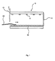
- Fig. 1Fig. 1
- den Verfahrensschritt des Einbringens eines Werkstücks in einen Durchlaufofen;the step of introducing a workpiece into a continuous furnace;
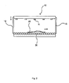
- Fig. 2Fig. 2
- den Verfahrensschritt der Erwärmung des gesamten Werkstücks innerhalb einer Heizstrecke;the step of heating the entire workpiece within a heating path;
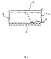
- Fig. 3Fig. 3
- den Verfahrensschritt der teilweisen Bewegung eines Werkstücks aus einem Durchlaufofen heraus;the step of partially moving a workpiece out of a continuous furnace;
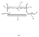
- Fig. 4Fig. 4
- ein Werkstück nach Durchführung des erfindungsgemäßen Verfahrens und Zuführung eines neuen Werkstücks;a workpiece after carrying out the method according to the invention and feeding a new workpiece;
- Fig. 5Fig. 5
- eine zweite Ausführungsform eines Durchlaufofens; unda second embodiment of a continuous furnace; and
- Fig. 6Fig. 6
- eine dritte Ausführungsform eines Durchlaufofens;a third embodiment of a continuous furnace;
- Fig. 7Fig. 7
- eine schematische Aufsicht auf mehrere Werkstücke in einem Durchlaufofen;a schematic plan view of several workpieces in a continuous furnace;
- Fig. 8Fig. 8
- den Verfahrensschritt des Einbringens mehrerer Werkstücke in einen Durchlaufofen;the step of introducing a plurality of workpieces in a continuous furnace;
- Fig. 9Fig. 9
- den Verfahrensschritt der gleichzeitigen Erwärmung mehrerer Werkstücke innerhalb einer Heizstrecke;the step of simultaneously heating a plurality of workpieces within a heating section;
- Fig. 10Fig. 10
- den Verfahrensschritt der teilweisen Bewegung eines Werkstücks aus einem Durchlaufofen heraus und die Entkoppelung wenigstens eines Werkstücks von einer Transporteinrichtung;the step of partially moving a workpiece out of a continuous furnace and decoupling at least one workpiece from a conveyor;
- Fig. 11Fig. 11
- ein erstes Werkstück nach der Erwärmung und die Ankopplung eines weiteren Werkstücks zurück an die Transporteinrichtung;a first workpiece after the heating and the coupling of another workpiece back to the transport device;
- Fig. 12Fig. 12
- ein zweites Werkstück nach der Erwärmung und die Ankopplung eines weiteren Werkstücks zurück an die Transporteinrichtung;a second workpiece after the heating and the coupling of another workpiece back to the transport device;
- Fig. 13Fig. 13
- ein drittes Werkstück nach der Erwärmung und Zuführung neuer Werkstücke in den Ofen; unda third workpiece after heating and feeding new workpieces into the oven; and
- Fig. 14Fig. 14
- eine schematische Aufsicht auf mehrere Werkstücke in einem Durchlaufofen.a schematic view of several workpieces in a continuous furnace.
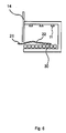
In
Bei den Werkstücken kann es sich um jegliche Bauteile handeln, bei denen in einem Endbereich andere Werkstoffeigenschaften gewünscht sind als in dem gegenüber liegenden Endbereich. Beispielsweise kann es sich um die B-Säule oder ein Formteil für die B-Säule eines Kraftfahrzeugs handeln, bei welcher der Fuß der B-Säule vergleichsweise duktil sein soll, während der Rest des Bauteils eine höhere Festigkeit aufweisen soll. Dabei ist bei einer Ausführungsform des erfindungsgemäßen Verfahrens vorgesehen, dass ein Werkstück 20 so in den Ofen 10 eingebracht wird, dass der Endbereich, in dem eine höhere Duktilität erreicht werden soll als in anderen Bereichen, in Transportrichtung des Werkstücks vorne liegt. Falls das Verfahren in einem Ofen durchgeführt wird, bei dem ein Werkstück aus der gleichen Öffnung entnommen wird, durch welche es in den Ofen eingebracht wurde, ist dies genau umgekehrt der Fall. Dann sollte derjenige Endbereich, in dem eine höhere Duktilität erreicht werden soll als in anderen Bereichen, in Transportrichtung des Werkstücks hinten liegen, wenn das Werkstück in den Ofen bewegt wird.The workpieces can be any components in which other material properties are desired in one end region than in the opposite end region. For example, it may be the B-pillar or a molding for the B-pillar of a motor vehicle, in which the foot of the B-pillar should be relatively ductile, while the rest of the component should have a higher strength. In one embodiment of the method according to the invention, provision is made for a
Das Gehäuse des Ofens 10 ist vorzugsweise geschlossen und weist lediglich eine Eingangs- und eine Ausgangsöffnung auf, durch die Werkstücke 20 an einer Seite in den Ofen eingebracht und an einer anderen Seite wieder aus ihm heraus bewegt werden können. Die Öffnungen sind jeweils mit Abdeckungen 12 und 13 verschließbar. Bei den Abdeckungen kann es sich beispielsweise um Ofenschieber handeln, die vor die Öffnungen geschoben werden können, um diese temporär zu verschließen oder freizugeben. Die Ofenschieber werden durch einen ansteuerbaren Antrieb bewegt.The housing of the
Vorzugsweise bewegen sich die Abdeckungen 12 und 13 nach oben, um die jeweilige Ofenöffnung freizugeben, damit ein Werkstück beispielsweise auf einem Rollenförderer in den Ofen bewegt werden kann. Die Werkstücke 20 können auch manuell oder durch Roboter auf der Transporteinrichtung abgelegt werden. Alternativ können die Werkstücke auf einer weiteren Transporteinrichtung zum Ofen 10 transportiert und an die Transporteinrichtung 30 des Ofens übergeben werden.Preferably, the
Die Abdeckungen 12 und 13 können die jeweilige Ofenöffnung auch durch eine Seitwärtsbewegung freigeben, oder die Abdeckungen bewegen sich nach unten, um den oberen Bereich einer Öffnung freizugeben. Dies ist beispielsweise vorteilhaft, wenn als Transporteinrichtung ein Förderer vorgesehen ist, der Werkstücke hängend durch den Ofen bewegt. Bei einem hängenden Transport sollten die Aufhängungen so angeordnet sein, dass das vordere Ende eines Werkstückes aus dem Ofen herausragen kann, während sich der verbleibende Teil noch im Ofeninnem befindet.The
Vorzugsweise kann wenigstens die Abdeckung 13 an der Ausgangsöffnung des Ofens 10 verschiedene Öffnungsgrade freigeben. Beispielsweise kann die Abdeckung 13 durch einen Antrieb so angesteuert werden, dass sie die Ausgangsöffnung vollständig oder nur teilweise freigibt. So können die Abdeckungen jeweils nur so weit geöffnet werden, wie es erforderlich ist, was unnötige Wärmeverluste verhindert.Preferably, at least the
Im Innern des Ofens sind geeignete Heizmittel 11 angeordnet, mit denen die Werkstücke 20 beim Durchlaufen des Ofens auf der Transporteinrichtung erwärmt werden können. Derartige Heizmittel sind aus dem Stand der Technik bekannt und werden nicht im Einzelnen erläutert. Auch alle weiteren erforderlichen Komponenten zum Betrieb des Ofens sind nicht Gegenstand der Erfindung und können vom Fachmann geeignet gewählt werden.In the interior of the furnace suitable heating means 11 are arranged, with which the
Die einzelnen Verfahrensschritte des erfindungsgemäßen Verfahrens und weitere Ausführungsmöglichkeiten sollen nun anhand der Figuren erläutert werden. Wie aus
Zweckmäßigerweise ist die Länge des Ofens 10 und die Transportgeschwindigkeit des Transportmittels 30 dabei entsprechend so gewählt, dass das Werkstück kontinuierlich durch den Ofen bewegt wird und sich im Werkstück die gewünschte Temperatur eingestellt hat, sobald die vordere Kante des Werkstücks 20 die Heizstrecke vollständig bis zum Ende des Ofens durchlaufen hat. Alternativ kann auch vorgesehen sein, die Bewegung der Transporteinrichtung kurzfristig zu unterbrechen, um das Werkstück für einen bestimmten Zeitraum innerhalb der Heizstrecke zu halten.Conveniently, the length of the
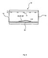
Anschließend gibt die Abdeckung 13 die Ausgangsöffnung des Ofens 10 frei, so dass ein Teil des Werkstücks aus dem Ofen heraus bewegt werden kann. Die Abdeckung 13 muss dazu nicht vollständig geöffnet werden, sondern kann beispielsweise nur den unteren Bereich der Ausgangsöffnung freigeben, wie es in
In dem Zeitraum des Stillstands der Transporteinrichtung 30 wird der erste Teilbereich 21 des Werkstücks 20, der sich noch innerhalb des Ofens und damit im Bereich der Heizmittel 11 befindet, weiter auf eine Temperatur erwärmt, die wenigstens der Härtetemperatur des Werkstoffs des Werkstücks entspricht. Beispielsweise wird dieser Teilbereich 21 auf eine Temperatur oberhalb von 700°C erwärmt, während der zweite Teilbereich 22 des Werkstücks außerhalb des Ofens nicht weiter erwärmt wird. In beiden Teilbereichen stellen sich so aufgrund der unterschiedlichen Verweildauer der Bereiche im Ofen unterschiedliche Temperaturen ein.In the period of the stoppage of the
In Abhängigkeit von den Umgebungsbedingungen außerhalb des Ofens 10 kühlt sich der zweite Teilbereich 22 außerhalb des Ofens 10 etwas ab, so dass er zuvor im Ofen auf eine Temperatur erwärmt worden sein muss, bei der sich trotz leichter Abkühlung am Ende des Verfahrens eine Temperatur T1 einstellt, bei der im Werkstoff nur eine teilweise Gefügeveränderung stattfindet, so dass dieser Bereich beim anschließenden schnellen Abschrecken vergleichsweise duktil bleibt. Im ersten Teilbereich 21 wird dagegen durch die längere Aufheizung innerhalb der Heizstrecke eine höhere Temperatur T2 eingestellt, die eine vollständige Gefügeveränderung und damit eine Austenitisierung bewirkt. Beim anschließenden Abschrecken stellen sich in diesem ersten Bereich somit höhere Festigkeiten ein. Grundsätzlich muss jedoch auch in diesem Bereich keine vollständige Gefügeveränderung stattfinden. Die Temperatur und damit das Maß der Gefügeveränderung sollte lediglich höher sein als im zweiten Teilbereich 21, um die gewünschten Unterschiede in den Materialeigenschaften zu erreichen.Depending on the ambient conditions outside the
Sobald sich mindestens die gewünschte Temperatur T2 im ersten Teilbereich 21 eingestellt hat, kann das Werkstück 20 aus dem Ofen entnommen werden, wie es in
In einem weiteren Ausführungsbeispiel der Erfindung wird das gesamte Werkstück im Ofen auf eine Temperatur erwärmt, die der Härtetemperatur des jeweiligen Werkstoffs entspricht. Sobald sich der zweite Teilbereich 22 des Werkstücks außerhalb der Heizstrecke befindet, kühlt er sich auf eine Temperatur unterhalb der Härtetemperatur ab, während der erste Teilbereich 21 des Werkstücks innerhalb des Ofens weiter auf Härtetemperatur gehalten wird. Auch so stellen sich in beiden Teilbereichen unterschiedliche Temperaturen ein.In a further embodiment of the invention, the entire workpiece is heated in the oven to a temperature corresponding to the hardening temperature of the respective material. As soon as the
Alternativ zu einem abgeschlossenen Durchlaufofen mit Gehäuse kann das erfindungsgemäße Verfahren auch mit einer Transporteinrichtung 30 durchgeführt werden, die Werkstücke lediglich durch eine mit einem Gehäuse umschlossene Heizstrecke bewegt, in der das Heizmittel angeordnet ist. Dies ist beispielsweise in
Die Taktzeiten der jeweiligen Abdeckungen 12 und 13 sind an die Verweildauer des Werkstücks 20 im Ofen, an die Geschwindigkeit der Transporteinrichtung 30 und auch an den Zeitraum des Stillstands der Transporteinrichtung 30 angepasst. Auch die verschiedenen Öffnungsgrade, insbesondere der Abdeckung 13 an der Ausgangsöffnung, sind ebenfalls an die Schritte bei dem erfindungsgemäßen Verfahren angepasst. So öffnet sich beispielsweise die Abdeckung 13 der Ausgangsöffnung des Ofens 10 und anschließend wird die Bewegung der Transporteinrichtung 30 unterbrochen. Danach kann sich die Abdeckung 13 gegebenenfalls auch wieder leicht absenken. Bevor sich die Transporteinrichtung 30 und damit das Werkstück wieder in Bewegung setzen, muss sich die Abdeckung 13 jedoch wieder öffnen. Gleichzeitig damit kann die Abdeckung 12 die Eingangsöffnung freigeben, um ein weiteres Werkstück aufzunehmen. Mit dieser Verfahrensführung lassen sich für die Erwärmung von Werkstücken Taktzeiten von 15 Sekunden erreichen.The cycle times of the respective covers 12 and 13 are adapted to the residence time of the
In einem Ausführungsbeispiel der Erfindung ist zur Erwärmung der Werkstücke kein Durchlaufofen vorgesehen, sondern ein Ofen weist lediglich eine Öffnung auf, durch welche Werkstücke eingebracht und wieder entnommen werden. Diese Bauform eines Ofens ist schematisch in
Selbstverständlich kann mit dem erfindungsgemäßen Verfahren jeweils nicht nur ein Werkstück erwärmt werden, sondern mehrere Werkstücke können gleichzeitig behandelt werden. Dies ist in
Werden mehrere Werkstücke gleichzeitig durch einen Durchlaufofen bewegt, kann in einem Ausführungsbeispiel der Erfindung vorgesehen sein, dass die Bewegung einzelner Werkstücke temporär unterbrochen wird, um den Ausstoß des Ofens an die Kapazitäten nachgeschalteter Stationen anzupassen. Dies soll im Folgenden anhand der
Wie aus der
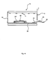
In
Nach dieser gemeinsamen Erwärmung der Werkstücke 20, 20' und 20" wird die Transportbewegung wenigstens eines der Werkstücke temporär unterbrochen. Wird für jedes Werkstück eine separate Transporteinrichtung verwendet, kann dies auf einfache Weise dadurch erfolgen, dass die Bewegung der betreffenden Transporteinrichtung temporär unterbrochen wird. Wird eine gemeinsame Transporteinrichtung für alle Werkstücke eingesetzt, kann eine temporäre Unterbrechung der Transportbewegung einzelner Werkstücke durch die temporäre Entkoppelung des jeweiligen Werkstücks von der Transporteinrichtung erfolgen. Die Entkoppelung kann je nach Ausführungsform der Transporteinrichtung auf unterschiedliche Weise realisiert werden. Aus
Die Stößel 40 und 41 befinden sich unterhalb der Werkstücke und führen eine getaktete Aufwärts- und Abwärtsbewegung durch, die von einer Steuereinrichtung gesteuert wird. Dabei können die Stößel durch Zwischenräume zwischen den einzelnen Rollen des Rollenförderers geführt sein und so ein oder mehrere Werkstücke getaktet anheben und wieder absenken. In dem in
Anschließend gibt die Abdeckung 13 die Ausgangsöffnung des Ofens 10 frei, so dass ein Teil des weiterbewegten Werkstücks 20 aus dem Ofen heraus bewegt werden kann. Sobald sich dieser Teilbereich 22 des Werkstücks 20 außerhalb des Ofens und damit außerhalb der Heizstrecke befindet, wird für dieses Werkstück 20 die Bewegung der Transporteinrichtung 30 für eine bestimmten Zeitspanne von beispielsweise 15-25 Sekunden unterbrochen.Subsequently, the
Sobald sich mindestens die gewünschte Temperatur T2 im ersten Teilbereich 21 eingestellt hat, kann das Werkstück 20 aus dem Ofen entnommen werden, wie es in
Für dieses Werkstück 20' wiederholen sich nun die erläuterten Schritte der partiellen Fortführung der Erwärmung, während das verbleibende Werkstück 20' weiterhin von der Transporteinrichtung 30 entkoppelt ist, wie es in
Die Taktzeiten der jeweiligen Abdeckungen 12 und 13 sind an die Verweildauer des Werkstücks 20 im Ofen, an die Geschwindigkeit der Transporteinrichtung 30 und auch an den Zeitraum des Stillstands der Transporteinrichtung 30 angepasst. An diese Parameter ist auch die Aufwärts- und Abwärtsbewegung der Stößel angepasst, wobei die Ansteuerung aller Komponenten vorzugsweise durch eine gemeinsame Steuereinrichtung erfolgt.The cycle times of the respective covers 12 and 13 are adapted to the residence time of the
In der
Bezugszeichenliste:
- 10
- Ofen, Durchlaufofen
- 11
- Heizmittel
- 12
- Abdeckung Eingangsöffnung; Trennschieber
- 13
- Abdeckung Ausgangsöffnung; Trennschieber
- 14
- Abdeckung
- 20,20',20"
- Werkstück
- 21,21',21"
- Erster Teilbereich eines Werkstücks mit höherer Temperatur
- 22,22',22"
- Zweiter Teilbereich eines Werkstücks mit niedrigerer Temperatur
- 30
- Transporteinrichtung, Rollenförderer
- 40,41
- Stößel (aktiviert)
- 42,43,44,45
- Stößel (deaktiviert)
- 10
- Oven, continuous furnace
- 11
- heating
- 12
- Cover entrance opening; separating slide
- 13
- Cover outlet opening; separating slide
- 14
- cover
- 20,20 ', 20 "
- workpiece
- 21,21 ', 21 "
- First part of a workpiece with a higher temperature
- 22,22 ', 22 "
- Second part of a workpiece with lower temperature
- 30
- Transport device, roller conveyor
- 40.41
- Plunger (activated)
- 42,43,44,45
- Plunger (deactivated)
Claims (17)
dadurch gekennzeichnet,
dass folgende Schritte erfolgen, nachdem ein gesamtes Werkstück (20;20';20") in einem ersten Schritt von den Heizmitteln erwärmt wurde:
characterized,
the following steps take place after an entire workpiece (20; 20 '; 20 ") has been heated by the heating means in a first step:
dadurch gekennzeichnet,
dass wenigstens ein Werkstück (20;20';20") in einem Durchlaufofen (10) erwärmt wird, und das Werkstück (20;20';20") durch eine Transporteinrichtung (30) durch den Durchlaufofen (10) bewegt und dabei auf einer Heizstrecke von Heizmitteln (11) erwärmt wird, wobei folgende Schritte erfolgen, nachdem die in Transportrichtung vorne liegende Seite eines Werkstücks (20;20';20") die Heizstrecke des Durchlaufofens (10) durchlaufen hat:
characterized,
that at least one workpiece (20; 20 '; 20 ") is heated in a continuous furnace (10) and the workpiece (20; 20';20") is moved through a continuous furnace (10) by a transport device (30) a heating section is heated by heating means (11), the following steps taking place after the side of a workpiece (20; 20 '; 20 ") lying in the transport direction has passed through the heating section of the continuous furnace (10):
dadurch gekennzeichnet,
dass der erste Teilbereich (21;21';21") des Werkstücks (20;20';20") durch das Verfahren auf eine Temperatur T1 erwärmt wird, die unterhalb der Härtetemperatur des Werkstoffs des Werkstücks (20;20';20") liegt, während der zweite Teilbereich (22;22';22") des Werkstücks (20;20';20") auf eine Temperatur T2 erwärmt wird, die der Härtetemperatur des Werkstoffs des Werkstücks (20;20';20") entspricht.Method according to one of the two claims 1 and 2,
characterized,
that the first part region (21; 21 '; 21 ") of the workpiece (20; 20';20") by the process to a temperature T 1 is heated, which is below the hardening temperature of the material of the workpiece (20; 20 '; 20 ") while the second portion (22; 22 ';22") of the workpiece (20; 20'; 20 ") is heated to a temperature T 2 equal to the hardening temperature of the material of the workpiece (20; 20 ';").
dadurch gekennzeichnet,
dass bei Bewegung der in Transportrichtung vorne liegenden Seite des Werkstücks (20;20';20") durch die Heizstrecke des Durchlaufofens (10) das gesamte Werkstück (20;20';20") auf eine Temperatur erwärmt wird, die unterhalb der Härtetemperatur des Werkstoffs des Werkstücks (20;20';20") liegt, und der zweite Teilbereich (22;22';22") des Werkstücks (20;20';20") innerhalb der Heizstrecke weiter auf eine Temperatur T2 erwärmt wird, die der Härtetemperatur des Werkstoffs des Werkstücks (20;20';20") entspricht, wenn sich der erste Teilbereich (21;21';21") des Werkstücks (20;20';20") außerhalb der Heizstrecke befindet.Method according to one of claims 2 to 3,
characterized,
in that, when the transport side of the workpiece (20; 20 '; 20 ") moves in the direction of travel of the continuous furnace (10), the entire workpiece (20; 20';20") is heated to a temperature below the hardening temperature the second part region (22, 22 ', 22 ") of the workpiece (20, 20', 20") within the heating path is further heated to a temperature T 2 which corresponds to the hardening temperature of the material of the workpiece (20; 20 '; 20 ") when the first portion (21; 21';21") of the workpiece (20; 20 '; 20 ") is outside the heating path.
dadurch gekennzeichnet,
dass wenigstens zwei Werkstücke (20;20';20") gleichzeitig mittels wenigstens einer Transporteinrichtung (30) nebeneinander durch den Durchlaufofen (10) bewegt und dabei auf einer Heizstrecke von Heizmitteln (11) erwärmt werden.Method according to one of claims 2 to 4,
characterized,
that at least two workpieces (20, 20 ', 20 ") are moved simultaneously by means of at least one transport device (30) side by side through the continuous furnace (10) and thereby heated by heating means (11) on a heating path.
dadurch gekennzeichnet,
dass folgende Schritte erfolgen, nachdem die in Transportrichtung vorne liegenden Seiten der Werkstücke (20;20';20") die Heizstrecke des Durchlaufofens (10) teilweise oder vollständig durchlaufen haben:
characterized,
the following steps take place after the sides of the workpieces (20; 20 '; 20 ") lying in front in the direction of transport have partially or completely passed through the heating path of the continuous furnace (10):
dadurch gekennzeichnet,
dass jedes der Werkstücke (20;20';20") mittels einer separaten Transporteinrichtung durch den Durchlaufofen (10) bewegt wird, und das Unterbrechen der Transportbewegung des wenigstens einen ersten Werkstücks (20';20") im Verfahrensschritt a) durch Unterbrechen der Bewegung der zugehörigen Transporteinrichtung erfolgt, während die Wiederaufnahme der Transportbewegung des wenigstens einen ersten Werkstücks (20';20") im Verfahrensschritt d) durch Wiederaufnahme der Bewegung der zugehörigen Transporteinrichtung erfolgt.Method according to claim 6,
characterized,
in that each of the workpieces (20; 20 '; 20 ") is moved through the continuous furnace (10) by means of a separate transport device, and interrupting the transport movement of the at least one first workpiece (20';20") in step a) by interrupting Movement of the associated transport device takes place while the resumption of the transport movement of the at least one first workpiece (20 ', 20 ") in step d) takes place by resuming the movement of the associated transport device.
dadurch gekennzeichnet,
dass alle Werkstücke (20;20';20") mittels einer gemeinsamen Transporteinrichtung (30) durch den Durchlaufofen (10) bewegt werden, und das Unterbrechen der Transportbewegung des wenigstens einen ersten Werkstücks (20';20") im Verfahrensschritt a) durch Entkoppeln des wenigstens einen ersten Werkstücks (20';20") von der Transporteinrichtung (30) erfolgt, während die Wiederaufnahme der Transportbewegung des wenigstens einen ersten Werkstücks (20';20") im Verfahrensschritt d) durch Ankoppeln des wenigstens einen ersten Werkstücks (20';20") an die Transporteinrichtung (30) erfolgt.Method according to claim 6,
characterized,
in that all workpieces (20; 20 '; 20 ") are moved by means of a common transport device (30) through the continuous furnace (10), and the transport movement of the at least one first workpiece (20';20") is interrupted in process step a) Decoupling of the at least one first workpiece (20 ', 20 ") from the transport device (30), while the resumption of the transport movement of the at least one first workpiece (20', 20") in method step d) by coupling the at least one first workpiece ( 20 ', 20 ") to the transport device (30).
dadurch gekennzeichnet,
dass die Transporteinrichtung (30) ein Rollenförderer ist, auf dem die Werkstücke (20;20';20") gleichzeitig nebeneinander durch die Heizstrecke des Durchlaufofen (10) bewegt werden, und dass das Entkoppeln wenigstens eines ersten Werkstücks (20';20") von dem Rollenförderer durch Anheben des Werkstücks (20';20") in eine Position erfolgt, in welcher das Werkstück (20';20") keinen Kontakt zum Rollenförderer hat, während das Ankoppeln des wenigstens eines ersten Werkstücks (20';20") an den Rollenförderer durch Absenken des Werkstücks (20';20") in eine Position erfolgt, in welcher das Werkstück (20';20") wieder Kontakt zum Rollenförderer hat und durch diesen in Transportrichtung bewegt wird.Method according to claim 8,
characterized,
in that the transport device (30) is a roller conveyor on which the workpieces (20; 20 '; 20 ") are simultaneously moved side by side through the heating path of the continuous furnace (10), and in that the decoupling of at least one first workpiece (20'; ) from the roller conveyor by lifting the workpiece (20 '; 20 ") to a position where the workpiece (20';20") is not in contact with the roller conveyor while coupling the at least one first workpiece (20 ';") takes place on the roller conveyor by lowering the workpiece (20 ', 20") into a position in which the workpiece (20', 20 ") again has contact with the roller conveyor and is moved by this in the transport direction.
dadurch gekennzeichnet,
dass das Anheben und Absenken eines Werkstücks (20';20") durch einen oder mehrere Stößel (40;41 ;42;43:44;45) erfolgt, die unterhalb der Werkstücke (20';20") angeordnet sind und sich getaktet aufwärts und abwärts bewegen, wobei die Aufwärtsbewegung wenigstens eines Stößels (40;41;42;43;44;45) das Anheben eines Werkstücks (20';20") von unten bewirkt, während die Abwärtsbewegung wenigstens eines Stößels (40;41;42;43;44;45) das Absenken eines Werkstücks (20';20") bewirkt, und dass diese Bewegung der Stößel (40;41;42;43;44;45) durch eine Steuereinrichtung angesteuert wird.Method according to claim 9,
characterized,
that the raising and lowering a workpiece (20 '; 20 ") by one or more rams (40; 41; 42; 43:; 45 44) takes place below the workpieces (20';20") are arranged and timed to move upward and downward, wherein the upward movement of at least one plunger (40; 41; 42; 43; 44; 45) causes lifting of a workpiece (20 '; 20 ") from below, while the downward movement of at least one plunger (40; 41; 42; 43; 44; 45) the Lowering a workpiece (20 ', 20 ") causes, and that this movement of the plunger (40; 41; 42; 43; 44; 45) is controlled by a control device.
dadurch gekennzeichnet,
dass die Transporteinrichtung (30) Mittel zum Bewegen des Werkstücks (20,20';20") soweit aus der Heizstrecke des Durchlaufofens (10) heraus aufweist, dass sich ein erster Teilbereich (21;21';21") des Werkstücks (20,20';20") noch innerhalb der Heizstrecke befindet, während sich ein zweiter Teilbereich (22;22';22") des Werkstücks (20,20';20") bereits außerhalb der Heizstrecke befindet, und dass die Bewegung der Transporteinrichtung (30) an dieser Position des Werkstücks (20,20';20") für einen vorbestimmten Zeitraum durch eine Steuereinrichtung unterbrechbar ist.Continuous furnace (10) for heating at least one workpiece (20,20 ', 20 "), in which the workpiece (20,20', 20") by a transport device (30) through the continuous furnace (10) movable and thereby on a heating line of heating means (11) is heatable,
characterized,
in that the transport device (30) has means for moving the workpiece (20, 20 ', 20 ") far enough out of the heating path of the continuous furnace (10) that a first subregion (21, 21', 21") of the workpiece (20 , 20 ', 20 ") is still within the heating path, while a second portion (22, 22', 22") of the workpiece (20, 20 '; 20 ") is already outside the heating path, and in that the movement of the transport device (30) at this position of the workpiece (20,20 '; 20 ") for a predetermined period of time by a control device is interruptible.
dadurch gekennzeichnet,
dass mehrere Werkstücke (20;20';20") gleichzeitig und nebeneinander mittels wenigstens einer Transporteinrichtung (30) durch den Durchlaufofen (10) bewegbar und dabei auf einer Heizstrecke von Heizmitteln (11) erwärmbar sind.Continuous furnace according to claim 11,
characterized,
a plurality of workpieces (20; 20 '; 20 ") can be moved simultaneously and side by side by means of at least one transport device (30) through the continuous furnace (10) and can be heated by heating means (11) on a heating path.
dadurch gekennzeichnet,
dass die wenigstens eine Transporteinrichtung (30) Mittel zum Bewegen eines Werkstücks (20;20';20") soweit aus der Heizstrecke des Durchlaufofens (10) heraus aufweist, dass sich ein erster Teilbereich (21;21';21") des jeweiligen Werkstücks (20;20';20") noch innerhalb der Heizstrecke befindet, während sich ein zweiter Teilbereich (22;22';22") des jeweiligen Werkstücks (20) bereits außerhalb der Heizstrecke befindet, und dass die Bewegung der wenigstens einen Transporteinrichtung (30) an dieser Position des jeweiligen Werkstücks (20;20';20") für eine vorbestimmten Zeitspanne unterbrechbar ist, und dass der Durchlaufofen (10) ferner Mittel zum temporären Unterbrechen der Transportbewegung von Werkstücken (20';20") während des Durchlaufens des Ofens (10) aufweist.Continuous furnace according to claim 12,
characterized,
in that the at least one transport device (30) has means for moving a workpiece (20; 20 '; 20 ") far enough out of the heating path of the continuous furnace (10) that a first subregion (21; 21';21") of the respective one Workpiece (20; 20 ', 20 ") is still within the heating section, while a second portion (22; 22';22") of the respective workpiece (20) is already outside the heating path, and that the movement of the at least one transport device (30) at this position of the respective workpiece (20; 20 '; 20 ") is interruptible for a predetermined period of time, and that the continuous furnace (10) further comprises means for temporarily interrupting the Transport movement of workpieces (20 ', 20 ") during the passage of the furnace (10).
dadurch gekennzeichnet,
dass für jedes der Werkstücke (20;20';20") eine separate Transporteinrichtung vorgesehen ist, mit welcher das jeweilige Werkstück (20;20';20") durch den Durchlaufofen (10) bewegbar ist, wobei die jeweiligen Transporteinrichtungen getrennt voneinander ansteuerbar sind und das temporäre Unterbrechen der Transportbewegung eines Werkstücks (20';20") durch das temporäre Unterbrechen der Bewegung der zugehörigen Transporteinrichtung erfolgen kann.Continuous furnace according to claim 13,
characterized,
that for each of the workpieces (20; 20 '; 20 ") has a separate transport means is provided with which the respective workpiece (20; 20';20") through the continuous furnace (10) is movable with the respective transport devices can be controlled separately from each other, and the temporary interruption of the transport movement of a workpiece (20 ', 20 ") can take place by the temporary interruption of the movement of the associated transport device.
dadurch gekennzeichnet,
dass für den Transport aller Werkstücke (20;20';20") durch den Durchlaufofen (10) eine gemeinsame Transporteinrichtung (30) vorgesehen ist, und dass der Durchlaufofen (10) Mittel zum temporären Entkoppeln einzelner Werkstücke (20';20") von der Transporteinrichtung (30) aufweist.Continuous furnace according to claim 13,
characterized,
that for the transport of all workpieces (20; 20 '; 20 ") through the continuous furnace (10) has a common transport device (30) is provided, and in that the continuous furnace (10) means for temporarily decoupling of individual workpieces (20';20") from the transport device (30).
dadurch gekennzeichnet,
dass die Transporteinrichtung (30) ein Rollenförderer ist, auf dem die Werkstücke (20;20';20") durch die Heizstrecke des Durchlaufofens (10) bewegbar sind, und dass das temporäre Entkoppeln eines Werkstücks (20';20") von dem Rollenförderer durch Anheben des Werkstücks (20';20") in eine Position erfolgt, in welcher das Werkstück (20';20") keinen Kontakt zum Rollenförderer hat, während das Ankoppeln eines Werkstücks (20';20") an den Rollenförderer durch Absenken des Werkstücks (20';20") in eine Position erfolgt, in welcher das Werkstück (20';20") wieder Kontakt zum Rollenförderer hat und durch diesen in Transportrichtung bewegbar ist.Continuous furnace according to claim 15,
characterized,
in that the transport device (30) is a roller conveyor on which the workpieces (20; 20 '; 20 ") are movable through the heating path of the continuous furnace (10), and in that the temporary decoupling of a workpiece (20';20") from the Roller conveyor by lifting the workpiece (20 ', 20 ") takes place in a position in which the workpiece (20';20") has no contact with the roller conveyor, while coupling a workpiece (20 ', 20 ") to the roller conveyor through Lowering of the workpiece (20 ', 20 ") takes place in a position in which the workpiece (20', 20") again has contact with the roller conveyor and is movable through this in the transport direction.
dadurch gekennzeichnet,
dass zum Anheben und Absenken eines Werkstücks (20';20") ein oder mehrere Stößel (40;41;42;43;44;45) vorgesehen sind, die sich unterhalb der Werkstücke (20';20") befinden, wobei die Stößel (40;41;42;43;44;45) für eine getaktete Aufwärts- und Abwärtsbewegung ausgebildet sind, und eine Steuereinrichtung vorgesehen ist, welche diese Aufwärts- und Abwärtsbewegung der Stößel (40;41;42;43;44;45) ansteuert.Continuous furnace according to claim 16,
characterized,
in that for raising and lowering a workpiece (20 '; 20 "), one or more rams (40; 41; 42; 43; 44; 45) are provided, which are located below the workpieces (20';20") Rams (40; 41; 42; 43; 44; 45) are designed for clocked upward and downward movement, and a control device is provided which controls this upward and downward movement of the rams (40; 41; 42; 43; 44; 45 ).
Applications Claiming Priority (2)
| Application Number | Priority Date | Filing Date | Title |
|---|---|---|---|
| DE102008019471 | 2008-04-17 | ||
| DE102008055980A DE102008055980A1 (en) | 2008-04-17 | 2008-11-05 | Process and continuous furnace for heating workpieces |
Publications (3)
| Publication Number | Publication Date |
|---|---|
| EP2110448A2 true EP2110448A2 (en) | 2009-10-21 |
| EP2110448A3 EP2110448A3 (en) | 2013-02-13 |
| EP2110448B1 EP2110448B1 (en) | 2018-10-24 |
Family
ID=40902112
Family Applications (1)
| Application Number | Title | Priority Date | Filing Date |
|---|---|---|---|
| EP09005231.7A Active EP2110448B1 (en) | 2008-04-17 | 2009-04-09 | Method and continuous furnace for heating workpieces |
Country Status (4)
| Country | Link |
|---|---|
| US (1) | US8529250B2 (en) |
| EP (1) | EP2110448B1 (en) |
| DE (1) | DE102008055980A1 (en) |
| ES (1) | ES2707225T3 (en) |
Cited By (6)
| Publication number | Priority date | Publication date | Assignee | Title |
|---|---|---|---|---|
| WO2010089103A1 (en) | 2009-02-03 | 2010-08-12 | Magna Ihv Gesellschaft Für Innenhochdruckverfahren Mbh | Method and furnace for making a metal workpiece with regions of different ductility |
| EP2336374A1 (en) * | 2009-12-16 | 2011-06-22 | Schwartz, Eva | Method and device for heating and partially cooling workpieces in a continuous furnace |
| EP2365100A2 (en) * | 2010-03-04 | 2011-09-14 | Kirchhoff Automotive Deutschland GmbH | Method for producing a molded part having at least two structure zones with different ductilities |
| DE102011114764A1 (en) | 2011-10-01 | 2013-04-04 | Volkswagen Aktiengesellschaft | Method for preparing hardened components of motor vehicle, involves cooling secondary portion of plate by forced convection, while plate is in holding position for predetermined time and then cured in mold form hardening tool |
| WO2014173703A1 (en) * | 2013-04-25 | 2014-10-30 | N. Bättenhausen Indrustrielle Wärme- Und Elektrorechnik Gmbh | Device for press hardening components |
| DE102020128925A1 (en) | 2020-11-03 | 2022-05-05 | Audi Aktiengesellschaft | Method and system for quenching metal components |
Families Citing this family (12)
| Publication number | Priority date | Publication date | Assignee | Title |
|---|---|---|---|---|
| US20110059412A1 (en) * | 2009-09-09 | 2011-03-10 | Thomas Robert Wiedemeier | Device and process for eradicating pests in wood |
| DE102012001742A1 (en) * | 2012-01-28 | 2013-08-01 | Volkswagen Aktiengesellschaft | Device, useful for heating, hot-forming and press-hardening of metal sheet workpieces, comprises a first heat station, a second heat station in which the workpieces are heated or held at a specified temperature, and a third heat station |
| DE102012103275A1 (en) * | 2012-04-16 | 2013-10-17 | Benteler Automobiltechnik Gmbh | Laminated furnace plant and method for operating the laminated-bed furnace |
| US10625323B2 (en) * | 2016-02-19 | 2020-04-21 | Ford Global Technologies, Llc | Method for monitoring quality of hot stamped components |
| US10335845B2 (en) | 2016-04-20 | 2019-07-02 | Ford Global Technologies, Llc | Hot-stamping furnace and method of hot stamping |
| US10350664B2 (en) | 2016-06-30 | 2019-07-16 | Ford Global Technologies, Llc | Furnace assembly and method for hot-stamping vehicle components |
| EP3559283A1 (en) * | 2016-12-22 | 2019-10-30 | Autotech Engineering S.L. | Method for heating a blank and heating system |
| CN107837993B (en) * | 2017-10-11 | 2021-03-02 | 盐城丰东特种炉业有限公司 | Continuous workpiece gluing and curing process |
| DE102019004618A1 (en) * | 2019-06-26 | 2020-12-31 | Bsn Thermprozesstechnik Gmbh | Roller hearth continuous furnace system and process for heating steel blanks coated with aluminum, silicon and / or zinc to hardening and pressing temperature |
| DE102020116593A1 (en) | 2020-06-24 | 2021-12-30 | AICHELIN Holding GmbH | Heat treatment plant and process for the production of molded components |
| DE102020129506A1 (en) | 2020-11-09 | 2022-05-12 | Ebner Industrieofenbau Gmbh | Centering device for metal blanks |
| EP4314683A1 (en) * | 2021-04-16 | 2024-02-07 | Aerospace Transmission Technologies GmbH | Control device and method for controlling a system and a process for the thermal treatment of metal workpieces |
Citations (2)
| Publication number | Priority date | Publication date | Assignee | Title |
|---|---|---|---|---|
| DE20014361U1 (en) | 2000-08-19 | 2000-10-12 | Benteler Werke Ag | B-pillar for a motor vehicle |
| EP1426454A1 (en) | 2002-12-03 | 2004-06-09 | Benteler Automobiltechnik GmbH | Method for producing a formed component with at least two regions of structure having different ductility and continuous furnace therefor |
Family Cites Families (13)
| Publication number | Priority date | Publication date | Assignee | Title |
|---|---|---|---|---|
| US4013403A (en) * | 1975-12-08 | 1977-03-22 | Pullman Incorporated | Support means for a roller hearth in a kiln |
| DE2642099C3 (en) * | 1976-09-18 | 1981-12-17 | Aeg-Elotherm Gmbh, 5630 Remscheid | Continuous induction furnace system for heating metallic workpieces |
| IT1085472B (en) * | 1977-07-28 | 1985-05-28 | Siti | EQUIPMENT AND PROCEDURE FOR UNLOADING OVENS FOR THE PRODUCTION OF TILES |
| US4554437A (en) * | 1984-05-17 | 1985-11-19 | Pet Incorporated | Tunnel oven |
| US5201401A (en) * | 1989-10-31 | 1993-04-13 | Sms Hasenclever Gmbh | Discharge conveying apparatus for an extrusion press |
| DE4034653A1 (en) * | 1990-10-31 | 1992-05-07 | Loi Ind Ofenanlagen | Pusher-type furnace - divides row of containers into separate blocks at end of each push cycle for insertion of treatment zone dividing doors |
| JP4480231B2 (en) * | 2000-05-30 | 2010-06-16 | トーヨーユニバーサル株式会社 | Convection brazing method and apparatus for metal workpiece |
| DE10314115A1 (en) * | 2003-03-28 | 2004-10-14 | Audi Ag | Process for forming a sheet from a tempered steel and device for carrying out the process |
| US8087407B2 (en) * | 2004-03-23 | 2012-01-03 | Middleby Corporation | Conveyor oven apparatus and method |
| EP1647789A1 (en) * | 2004-10-04 | 2006-04-19 | Ngk Insulators, Ltd. | Continuous heat treatment furnace and heat treatment method |
| US7340992B1 (en) * | 2005-01-27 | 2008-03-11 | Wolfe Electric, Inc. | Dual belt conveyor oven |
| DE102008030279A1 (en) * | 2008-06-30 | 2010-01-07 | Benteler Automobiltechnik Gmbh | Partial thermoforming and curing by means of infrared lamp heating |
| DE102010010156A1 (en) * | 2010-03-04 | 2011-09-08 | Kirchhoff Automotive Deutschland Gmbh | Process for producing a molded part with at least two structural areas of different ductility |
-
2008
- 2008-11-05 DE DE102008055980A patent/DE102008055980A1/en not_active Ceased
-
2009
- 2009-04-09 ES ES09005231T patent/ES2707225T3/en active Active
- 2009-04-09 EP EP09005231.7A patent/EP2110448B1/en active Active
- 2009-04-13 US US12/422,611 patent/US8529250B2/en active Active
Patent Citations (2)
| Publication number | Priority date | Publication date | Assignee | Title |
|---|---|---|---|---|
| DE20014361U1 (en) | 2000-08-19 | 2000-10-12 | Benteler Werke Ag | B-pillar for a motor vehicle |
| EP1426454A1 (en) | 2002-12-03 | 2004-06-09 | Benteler Automobiltechnik GmbH | Method for producing a formed component with at least two regions of structure having different ductility and continuous furnace therefor |
Cited By (10)
| Publication number | Priority date | Publication date | Assignee | Title |
|---|---|---|---|---|
| WO2010089103A1 (en) | 2009-02-03 | 2010-08-12 | Magna Ihv Gesellschaft Für Innenhochdruckverfahren Mbh | Method and furnace for making a metal workpiece with regions of different ductility |
| EP2336374A1 (en) * | 2009-12-16 | 2011-06-22 | Schwartz, Eva | Method and device for heating and partially cooling workpieces in a continuous furnace |
| WO2011082934A1 (en) * | 2009-12-16 | 2011-07-14 | Schwartz, Eva | Method and device for heating and partially cooling work pieces in a continuous furnace |
| EP2365100A2 (en) * | 2010-03-04 | 2011-09-14 | Kirchhoff Automotive Deutschland GmbH | Method for producing a molded part having at least two structure zones with different ductilities |
| EP2365100A3 (en) * | 2010-03-04 | 2014-02-19 | Kirchhoff Automotive Deutschland GmbH | Method for producing a molded part having at least two structure zones with different ductilities |
| DE102011114764A1 (en) | 2011-10-01 | 2013-04-04 | Volkswagen Aktiengesellschaft | Method for preparing hardened components of motor vehicle, involves cooling secondary portion of plate by forced convection, while plate is in holding position for predetermined time and then cured in mold form hardening tool |
| DE102011114764B4 (en) * | 2011-10-01 | 2016-04-21 | Volkswagen Aktiengesellschaft | Process for the production of form-hardened components and continuous furnace for heating a board provided for molding |
| WO2014173703A1 (en) * | 2013-04-25 | 2014-10-30 | N. Bättenhausen Indrustrielle Wärme- Und Elektrorechnik Gmbh | Device for press hardening components |
| US10590500B2 (en) | 2013-04-25 | 2020-03-17 | N. Bättenhausen Industrielle Wärme- und Elektrotechnik GmbH | Apparatus for the press hardening of components |
| DE102020128925A1 (en) | 2020-11-03 | 2022-05-05 | Audi Aktiengesellschaft | Method and system for quenching metal components |
Also Published As
| Publication number | Publication date |
|---|---|
| ES2707225T3 (en) | 2019-04-03 |
| EP2110448B1 (en) | 2018-10-24 |
| US20090263758A1 (en) | 2009-10-22 |
| DE102008055980A1 (en) | 2009-10-29 |
| US8529250B2 (en) | 2013-09-10 |
| EP2110448A3 (en) | 2013-02-13 |
Similar Documents
| Publication | Publication Date | Title |
|---|---|---|
| EP2110448B1 (en) | Method and continuous furnace for heating workpieces | |
| EP2365100B1 (en) | Method and apparatus for producing a molded part having at least two structure zones with different ductilities | |
| DE102005032113B3 (en) | Thermal deformation and partial hardening apparatus, e.g. for automobile components, comprises mold of at least two parts, each formed from segments adjustable to different temperatures | |
| EP2993241B1 (en) | Method and press for manufacturing cured sheet metal components, in sections at least | |
| DE102009015013B4 (en) | Process for producing partially hardened steel components | |
| EP2233593B1 (en) | Method and device for thermal recasting of pressure-hardened casting components made of sheet metal | |
| EP3172345B1 (en) | Method for heating up steel sheets | |
| DE102007012180B3 (en) | Heat treating method for semi-finished steel products is carried out in continuous furnace, semi-finished product being passed into first zone and then moved so that section of it is in second zone at a different temperature from first | |
| EP1426454A1 (en) | Method for producing a formed component with at least two regions of structure having different ductility and continuous furnace therefor | |
| EP2864506B1 (en) | Method and device for producing a press-hardened metal component | |
| EP1954997B1 (en) | Method and apparatus for heating steel components in a continuous furnace | |
| DE102005055494B3 (en) | Production of a metallic flat product, especially a sheet steel blank, used in the construction of chassis components comprises heating the flat product to a deforming temperature using conduction heating directly before deforming | |
| EP2548975A1 (en) | Method and device for producing a hardened metallic component with at least two areas of different ductility | |
| WO2010048951A1 (en) | Method and apparatus for controlling the temperature of a steel sheet element | |
| DE112017002311T5 (en) | Thermoforming tool with infrared light source | |
| DE102011114764B4 (en) | Process for the production of form-hardened components and continuous furnace for heating a board provided for molding | |
| DE102012012518A1 (en) | Hot forming tool for the production of molded parts | |
| EP2883967B1 (en) | Method and device for post-treatment of a hardened metallic moulded part by means of electrical resistance heating | |
| EP3408416B1 (en) | Heat treatment method and heat treatment device | |
| DE102017109613B3 (en) | Hot forming line with tempering station and method of operation | |
| DE102009042387B4 (en) | Method for producing partially hardened components from sheet steel | |
| WO2011082934A1 (en) | Method and device for heating and partially cooling work pieces in a continuous furnace | |
| EP3420111B1 (en) | Process for targeted heat treatment of individual component zones | |
| EP2439289B1 (en) | Method and furnace for treating workpieces | |
| WO2023284905A1 (en) | Multi-zone heating process, heating apparatus and process for producing a motor vehicle component |
Legal Events
| Date | Code | Title | Description |
|---|---|---|---|
| PUAI | Public reference made under article 153(3) epc to a published international application that has entered the european phase |
Free format text: ORIGINAL CODE: 0009012 |
|
| AK | Designated contracting states |
Kind code of ref document: A2 Designated state(s): AT BE BG CH CY CZ DE DK EE ES FI FR GB GR HR HU IE IS IT LI LT LU LV MC MK MT NL NO PL PT RO SE SI SK TR |
|
| RAP1 | Party data changed (applicant data changed or rights of an application transferred) |
Owner name: SCHWARTZ, EVA |
|
| PUAL | Search report despatched |
Free format text: ORIGINAL CODE: 0009013 |
|
| AK | Designated contracting states |
Kind code of ref document: A3 Designated state(s): AT BE BG CH CY CZ DE DK EE ES FI FR GB GR HR HU IE IS IT LI LT LU LV MC MK MT NL NO PL PT RO SE SI SK TR |
|
| AX | Request for extension of the european patent |
Extension state: AL BA RS |
|
| RIC1 | Information provided on ipc code assigned before grant |
Ipc: F27B 9/30 20060101ALI20130104BHEP Ipc: F27B 9/02 20060101ALI20130104BHEP Ipc: C21D 9/00 20060101AFI20130104BHEP Ipc: B62D 25/04 20060101ALI20130104BHEP Ipc: B21J 1/06 20060101ALI20130104BHEP Ipc: F27B 9/24 20060101ALI20130104BHEP |
|
| RAP1 | Party data changed (applicant data changed or rights of an application transferred) |
Owner name: SCHWARTZ, EVA |
|
| 17P | Request for examination filed |
Effective date: 20130813 |
|
| RBV | Designated contracting states (corrected) |
Designated state(s): AT BE BG CH CY CZ DE DK EE ES FI FR GB GR HR HU IE IS IT LI LT LU LV MC MK MT NL NO PL PT RO SE SI SK TR |
|
| RAP1 | Party data changed (applicant data changed or rights of an application transferred) |
Owner name: SCHWARTZ GMBH |
|
| 17Q | First examination report despatched |
Effective date: 20160217 |
|
| STAA | Information on the status of an ep patent application or granted ep patent |
Free format text: STATUS: EXAMINATION IS IN PROGRESS |
|
| GRAP | Despatch of communication of intention to grant a patent |
Free format text: ORIGINAL CODE: EPIDOSNIGR1 |
|
| STAA | Information on the status of an ep patent application or granted ep patent |
Free format text: STATUS: GRANT OF PATENT IS INTENDED |
|
| INTG | Intention to grant announced |
Effective date: 20180731 |
|
| GRAS | Grant fee paid |
Free format text: ORIGINAL CODE: EPIDOSNIGR3 |
|
| GRAA | (expected) grant |
Free format text: ORIGINAL CODE: 0009210 |
|
| STAA | Information on the status of an ep patent application or granted ep patent |
Free format text: STATUS: THE PATENT HAS BEEN GRANTED |
|
| AK | Designated contracting states |
Kind code of ref document: B1 Designated state(s): AT BE BG CH CY CZ DE DK EE ES FI FR GB GR HR HU IE IS IT LI LT LU LV MC MK MT NL NO PL PT RO SE SI SK TR |
|
| REG | Reference to a national code |
Ref country code: GB Ref legal event code: FG4D Free format text: NOT ENGLISH |
|
| REG | Reference to a national code |
Ref country code: CH Ref legal event code: EP |
|
| REG | Reference to a national code |
Ref country code: IE Ref legal event code: FG4D Free format text: LANGUAGE OF EP DOCUMENT: GERMAN |
|
| REG | Reference to a national code |
Ref country code: AT Ref legal event code: REF Ref document number: 1056730 Country of ref document: AT Kind code of ref document: T Effective date: 20181115 |
|
| REG | Reference to a national code |
Ref country code: DE Ref legal event code: R096 Ref document number: 502009015389 Country of ref document: DE |
|
| REG | Reference to a national code |
Ref country code: SE Ref legal event code: TRGR |
|
| REG | Reference to a national code |
Ref country code: NL Ref legal event code: MP Effective date: 20181024 |
|
| REG | Reference to a national code |
Ref country code: LT Ref legal event code: MG4D |
|
| PG25 | Lapsed in a contracting state [announced via postgrant information from national office to epo] |
Ref country code: NL Free format text: LAPSE BECAUSE OF FAILURE TO SUBMIT A TRANSLATION OF THE DESCRIPTION OR TO PAY THE FEE WITHIN THE PRESCRIBED TIME-LIMIT Effective date: 20181024 |
|
| REG | Reference to a national code |
Ref country code: ES Ref legal event code: FG2A Ref document number: 2707225 Country of ref document: ES Kind code of ref document: T3 Effective date: 20190403 |
|
| PG25 | Lapsed in a contracting state [announced via postgrant information from national office to epo] |
Ref country code: LV Free format text: LAPSE BECAUSE OF FAILURE TO SUBMIT A TRANSLATION OF THE DESCRIPTION OR TO PAY THE FEE WITHIN THE PRESCRIBED TIME-LIMIT Effective date: 20181024 Ref country code: LT Free format text: LAPSE BECAUSE OF FAILURE TO SUBMIT A TRANSLATION OF THE DESCRIPTION OR TO PAY THE FEE WITHIN THE PRESCRIBED TIME-LIMIT Effective date: 20181024 Ref country code: NO Free format text: LAPSE BECAUSE OF FAILURE TO SUBMIT A TRANSLATION OF THE DESCRIPTION OR TO PAY THE FEE WITHIN THE PRESCRIBED TIME-LIMIT Effective date: 20190124 Ref country code: FI Free format text: LAPSE BECAUSE OF FAILURE TO SUBMIT A TRANSLATION OF THE DESCRIPTION OR TO PAY THE FEE WITHIN THE PRESCRIBED TIME-LIMIT Effective date: 20181024 Ref country code: IS Free format text: LAPSE BECAUSE OF FAILURE TO SUBMIT A TRANSLATION OF THE DESCRIPTION OR TO PAY THE FEE WITHIN THE PRESCRIBED TIME-LIMIT Effective date: 20190224 Ref country code: BG Free format text: LAPSE BECAUSE OF FAILURE TO SUBMIT A TRANSLATION OF THE DESCRIPTION OR TO PAY THE FEE WITHIN THE PRESCRIBED TIME-LIMIT Effective date: 20190124 Ref country code: HR Free format text: LAPSE BECAUSE OF FAILURE TO SUBMIT A TRANSLATION OF THE DESCRIPTION OR TO PAY THE FEE WITHIN THE PRESCRIBED TIME-LIMIT Effective date: 20181024 Ref country code: PL Free format text: LAPSE BECAUSE OF FAILURE TO SUBMIT A TRANSLATION OF THE DESCRIPTION OR TO PAY THE FEE WITHIN THE PRESCRIBED TIME-LIMIT Effective date: 20181024 |
|
| PG25 | Lapsed in a contracting state [announced via postgrant information from national office to epo] |
Ref country code: GR Free format text: LAPSE BECAUSE OF FAILURE TO SUBMIT A TRANSLATION OF THE DESCRIPTION OR TO PAY THE FEE WITHIN THE PRESCRIBED TIME-LIMIT Effective date: 20190125 Ref country code: PT Free format text: LAPSE BECAUSE OF FAILURE TO SUBMIT A TRANSLATION OF THE DESCRIPTION OR TO PAY THE FEE WITHIN THE PRESCRIBED TIME-LIMIT Effective date: 20190224 |
|
| REG | Reference to a national code |
Ref country code: DE Ref legal event code: R097 Ref document number: 502009015389 Country of ref document: DE |
|
| PG25 | Lapsed in a contracting state [announced via postgrant information from national office to epo] |
Ref country code: DK Free format text: LAPSE BECAUSE OF FAILURE TO SUBMIT A TRANSLATION OF THE DESCRIPTION OR TO PAY THE FEE WITHIN THE PRESCRIBED TIME-LIMIT Effective date: 20181024 Ref country code: IT Free format text: LAPSE BECAUSE OF FAILURE TO SUBMIT A TRANSLATION OF THE DESCRIPTION OR TO PAY THE FEE WITHIN THE PRESCRIBED TIME-LIMIT Effective date: 20181024 |
|
| PG25 | Lapsed in a contracting state [announced via postgrant information from national office to epo] |
Ref country code: RO Free format text: LAPSE BECAUSE OF FAILURE TO SUBMIT A TRANSLATION OF THE DESCRIPTION OR TO PAY THE FEE WITHIN THE PRESCRIBED TIME-LIMIT Effective date: 20181024 Ref country code: EE Free format text: LAPSE BECAUSE OF FAILURE TO SUBMIT A TRANSLATION OF THE DESCRIPTION OR TO PAY THE FEE WITHIN THE PRESCRIBED TIME-LIMIT Effective date: 20181024 Ref country code: SK Free format text: LAPSE BECAUSE OF FAILURE TO SUBMIT A TRANSLATION OF THE DESCRIPTION OR TO PAY THE FEE WITHIN THE PRESCRIBED TIME-LIMIT Effective date: 20181024 |
|
| PLBE | No opposition filed within time limit |
Free format text: ORIGINAL CODE: 0009261 |
|
| STAA | Information on the status of an ep patent application or granted ep patent |
Free format text: STATUS: NO OPPOSITION FILED WITHIN TIME LIMIT |
|
| 26N | No opposition filed |
Effective date: 20190725 |
|
| PG25 | Lapsed in a contracting state [announced via postgrant information from national office to epo] |
Ref country code: SI Free format text: LAPSE BECAUSE OF FAILURE TO SUBMIT A TRANSLATION OF THE DESCRIPTION OR TO PAY THE FEE WITHIN THE PRESCRIBED TIME-LIMIT Effective date: 20181024 |
|
| REG | Reference to a national code |
Ref country code: CH Ref legal event code: PL |
|
| REG | Reference to a national code |
Ref country code: BE Ref legal event code: MM Effective date: 20190430 |
|
| GBPC | Gb: european patent ceased through non-payment of renewal fee |
Effective date: 20190409 |
|
| PG25 | Lapsed in a contracting state [announced via postgrant information from national office to epo] |
Ref country code: LU Free format text: LAPSE BECAUSE OF NON-PAYMENT OF DUE FEES Effective date: 20190409 Ref country code: MC Free format text: LAPSE BECAUSE OF FAILURE TO SUBMIT A TRANSLATION OF THE DESCRIPTION OR TO PAY THE FEE WITHIN THE PRESCRIBED TIME-LIMIT Effective date: 20181024 |
|
| PG25 | Lapsed in a contracting state [announced via postgrant information from national office to epo] |
Ref country code: CH Free format text: LAPSE BECAUSE OF NON-PAYMENT OF DUE FEES Effective date: 20190430 Ref country code: GB Free format text: LAPSE BECAUSE OF NON-PAYMENT OF DUE FEES Effective date: 20190409 Ref country code: LI Free format text: LAPSE BECAUSE OF NON-PAYMENT OF DUE FEES Effective date: 20190430 |
|
| PG25 | Lapsed in a contracting state [announced via postgrant information from national office to epo] |
Ref country code: FR Free format text: LAPSE BECAUSE OF NON-PAYMENT OF DUE FEES Effective date: 20190430 Ref country code: BE Free format text: LAPSE BECAUSE OF NON-PAYMENT OF DUE FEES Effective date: 20190430 |
|
| PG25 | Lapsed in a contracting state [announced via postgrant information from national office to epo] |
Ref country code: TR Free format text: LAPSE BECAUSE OF FAILURE TO SUBMIT A TRANSLATION OF THE DESCRIPTION OR TO PAY THE FEE WITHIN THE PRESCRIBED TIME-LIMIT Effective date: 20181024 |
|
| PG25 | Lapsed in a contracting state [announced via postgrant information from national office to epo] |
Ref country code: IE Free format text: LAPSE BECAUSE OF NON-PAYMENT OF DUE FEES Effective date: 20190409 |
|
| PG25 | Lapsed in a contracting state [announced via postgrant information from national office to epo] |
Ref country code: CY Free format text: LAPSE BECAUSE OF FAILURE TO SUBMIT A TRANSLATION OF THE DESCRIPTION OR TO PAY THE FEE WITHIN THE PRESCRIBED TIME-LIMIT Effective date: 20181024 |
|
| PG25 | Lapsed in a contracting state [announced via postgrant information from national office to epo] |
Ref country code: MT Free format text: LAPSE BECAUSE OF FAILURE TO SUBMIT A TRANSLATION OF THE DESCRIPTION OR TO PAY THE FEE WITHIN THE PRESCRIBED TIME-LIMIT Effective date: 20181024 Ref country code: HU Free format text: LAPSE BECAUSE OF FAILURE TO SUBMIT A TRANSLATION OF THE DESCRIPTION OR TO PAY THE FEE WITHIN THE PRESCRIBED TIME-LIMIT; INVALID AB INITIO Effective date: 20090409 |
|
| PG25 | Lapsed in a contracting state [announced via postgrant information from national office to epo] |
Ref country code: MK Free format text: LAPSE BECAUSE OF FAILURE TO SUBMIT A TRANSLATION OF THE DESCRIPTION OR TO PAY THE FEE WITHIN THE PRESCRIBED TIME-LIMIT Effective date: 20181024 |
|
| PGFP | Annual fee paid to national office [announced via postgrant information from national office to epo] |
Ref country code: ES Payment date: 20230627 Year of fee payment: 15 Ref country code: DE Payment date: 20230420 Year of fee payment: 15 Ref country code: CZ Payment date: 20230403 Year of fee payment: 15 |
|
| PGFP | Annual fee paid to national office [announced via postgrant information from national office to epo] |
Ref country code: SE Payment date: 20230420 Year of fee payment: 15 Ref country code: AT Payment date: 20230420 Year of fee payment: 15 |