EP2110448A2 - Procédé et four à passage continu destinés au chauffage de pièces à usiner - Google Patents
Procédé et four à passage continu destinés au chauffage de pièces à usiner Download PDFInfo
- Publication number
- EP2110448A2 EP2110448A2 EP09005231A EP09005231A EP2110448A2 EP 2110448 A2 EP2110448 A2 EP 2110448A2 EP 09005231 A EP09005231 A EP 09005231A EP 09005231 A EP09005231 A EP 09005231A EP 2110448 A2 EP2110448 A2 EP 2110448A2
- Authority
- EP
- European Patent Office
- Prior art keywords
- workpiece
- continuous furnace
- heating
- transport device
- transport
- Prior art date
- Legal status (The legal status is an assumption and is not a legal conclusion. Google has not performed a legal analysis and makes no representation as to the accuracy of the status listed.)
- Granted
Links
Images


Classifications
-
- C—CHEMISTRY; METALLURGY
- C21—METALLURGY OF IRON
- C21D—MODIFYING THE PHYSICAL STRUCTURE OF FERROUS METALS; GENERAL DEVICES FOR HEAT TREATMENT OF FERROUS OR NON-FERROUS METALS OR ALLOYS; MAKING METAL MALLEABLE, e.g. BY DECARBURISATION OR TEMPERING
- C21D9/00—Heat treatment, e.g. annealing, hardening, quenching or tempering, adapted for particular articles; Furnaces therefor
- C21D9/0056—Furnaces through which the charge is moved in a horizontal straight path
-
- C—CHEMISTRY; METALLURGY
- C21—METALLURGY OF IRON
- C21D—MODIFYING THE PHYSICAL STRUCTURE OF FERROUS METALS; GENERAL DEVICES FOR HEAT TREATMENT OF FERROUS OR NON-FERROUS METALS OR ALLOYS; MAKING METAL MALLEABLE, e.g. BY DECARBURISATION OR TEMPERING
- C21D9/00—Heat treatment, e.g. annealing, hardening, quenching or tempering, adapted for particular articles; Furnaces therefor
- C21D9/0068—Heat treatment, e.g. annealing, hardening, quenching or tempering, adapted for particular articles; Furnaces therefor for particular articles not mentioned below
-
- F—MECHANICAL ENGINEERING; LIGHTING; HEATING; WEAPONS; BLASTING
- F27—FURNACES; KILNS; OVENS; RETORTS
- F27B—FURNACES, KILNS, OVENS, OR RETORTS IN GENERAL; OPEN SINTERING OR LIKE APPARATUS
- F27B9/00—Furnaces through which the charge is moved mechanically, e.g. of tunnel type; Similar furnaces in which the charge moves by gravity
- F27B9/14—Furnaces through which the charge is moved mechanically, e.g. of tunnel type; Similar furnaces in which the charge moves by gravity characterised by the path of the charge during treatment; characterised by the means by which the charge is moved during treatment
- F27B9/20—Furnaces through which the charge is moved mechanically, e.g. of tunnel type; Similar furnaces in which the charge moves by gravity characterised by the path of the charge during treatment; characterised by the means by which the charge is moved during treatment the charge moving in a substantially straight path tunnel furnace
- F27B9/24—Furnaces through which the charge is moved mechanically, e.g. of tunnel type; Similar furnaces in which the charge moves by gravity characterised by the path of the charge during treatment; characterised by the means by which the charge is moved during treatment the charge moving in a substantially straight path tunnel furnace being carried by a conveyor
- F27B9/2407—Furnaces through which the charge is moved mechanically, e.g. of tunnel type; Similar furnaces in which the charge moves by gravity characterised by the path of the charge during treatment; characterised by the means by which the charge is moved during treatment the charge moving in a substantially straight path tunnel furnace being carried by a conveyor the conveyor being constituted by rollers (roller hearth furnace)
-
- F—MECHANICAL ENGINEERING; LIGHTING; HEATING; WEAPONS; BLASTING
- F27—FURNACES; KILNS; OVENS; RETORTS
- F27B—FURNACES, KILNS, OVENS, OR RETORTS IN GENERAL; OPEN SINTERING OR LIKE APPARATUS
- F27B9/00—Furnaces through which the charge is moved mechanically, e.g. of tunnel type; Similar furnaces in which the charge moves by gravity
- F27B9/14—Furnaces through which the charge is moved mechanically, e.g. of tunnel type; Similar furnaces in which the charge moves by gravity characterised by the path of the charge during treatment; characterised by the means by which the charge is moved during treatment
- F27B9/20—Furnaces through which the charge is moved mechanically, e.g. of tunnel type; Similar furnaces in which the charge moves by gravity characterised by the path of the charge during treatment; characterised by the means by which the charge is moved during treatment the charge moving in a substantially straight path tunnel furnace
- F27B9/24—Furnaces through which the charge is moved mechanically, e.g. of tunnel type; Similar furnaces in which the charge moves by gravity characterised by the path of the charge during treatment; characterised by the means by which the charge is moved during treatment the charge moving in a substantially straight path tunnel furnace being carried by a conveyor
- F27B9/2469—Furnaces through which the charge is moved mechanically, e.g. of tunnel type; Similar furnaces in which the charge moves by gravity characterised by the path of the charge during treatment; characterised by the means by which the charge is moved during treatment the charge moving in a substantially straight path tunnel furnace being carried by a conveyor the conveyor being constituted by rollable bodies
-
- F—MECHANICAL ENGINEERING; LIGHTING; HEATING; WEAPONS; BLASTING
- F27—FURNACES; KILNS; OVENS; RETORTS
- F27B—FURNACES, KILNS, OVENS, OR RETORTS IN GENERAL; OPEN SINTERING OR LIKE APPARATUS
- F27B9/00—Furnaces through which the charge is moved mechanically, e.g. of tunnel type; Similar furnaces in which the charge moves by gravity
- F27B9/30—Details, accessories, or equipment peculiar to furnaces of these types
-
- F—MECHANICAL ENGINEERING; LIGHTING; HEATING; WEAPONS; BLASTING
- F27—FURNACES; KILNS; OVENS; RETORTS
- F27D—DETAILS OR ACCESSORIES OF FURNACES, KILNS, OVENS, OR RETORTS, IN SO FAR AS THEY ARE OF KINDS OCCURRING IN MORE THAN ONE KIND OF FURNACE
- F27D5/00—Supports, screens, or the like for the charge within the furnace
-
- C—CHEMISTRY; METALLURGY
- C21—METALLURGY OF IRON
- C21D—MODIFYING THE PHYSICAL STRUCTURE OF FERROUS METALS; GENERAL DEVICES FOR HEAT TREATMENT OF FERROUS OR NON-FERROUS METALS OR ALLOYS; MAKING METAL MALLEABLE, e.g. BY DECARBURISATION OR TEMPERING
- C21D1/00—General methods or devices for heat treatment, e.g. annealing, hardening, quenching or tempering
- C21D1/62—Quenching devices
- C21D1/673—Quenching devices for die quenching
-
- C—CHEMISTRY; METALLURGY
- C21—METALLURGY OF IRON
- C21D—MODIFYING THE PHYSICAL STRUCTURE OF FERROUS METALS; GENERAL DEVICES FOR HEAT TREATMENT OF FERROUS OR NON-FERROUS METALS OR ALLOYS; MAKING METAL MALLEABLE, e.g. BY DECARBURISATION OR TEMPERING
- C21D2221/00—Treating localised areas of an article
Definitions
- the invention relates to a method for heating at least one workpiece in a furnace, in which the workpiece is heated by heating means.
- the invention further relates to an associated furnace for carrying out the method.
- molded components In the field of production and treatment of molded components, it is customary to produce moldings specifically with desired material properties. For example, in the automotive industry, components such as control arms, B-pillars, or automotive bumpers are cured by complete heating followed by quenching. This may be followed by an incentive procedure for a fee. In various applications of automotive engineering, however, it is advantageous that molded components have different material properties in different areas. For example, it may be provided that a component in one area should have a high strength, but in another area a higher ductility in relation to it.
- components can be reinforced by additional sheets. Also suitable is the annealing of previously fully cured mold components at the appropriate locations to achieve higher ductility regions. However, this leads to intolerable changes in shape in the component.
- EP 1 426 454 A1 a method for producing a molded component having at least two structural areas of different ductility and a continuous furnace for carrying out the method.
- a semifinished product to be heated is transported as a blank or preformed component through a continuous furnace, which comprises two juxtaposed zones in which different temperature levels are set.
- the component is heated in the oven to two different temperatures and then subjected to a thermoforming process and / or a hardening process.
- a more ductile microstructure arises in the higher-heated region of the component, while a solid or high-strength microstructure sets in the less heated region.
- the German Utility Model DE 200 14 361 U1 describes a method for producing a B-pillar with different microstructure ranges, in which the B-pillar is heated in an oven and austenitized with it, and then cured in a cooled mold.
- the B-pillar is heated in an oven and austenitized with it, and then cured in a cooled mold.
- the oven large areas of the board or the semi-finished product used are isolated against the effect of temperature, so that sets in the shielded areas no martensitic material structure with high strengths.
- this represents an unsafe process, since in the case of a malfunction heat can penetrate into the covered areas and thus these areas are heated to hardening temperature.
- the known methods are not suitable in particular for mass operation with a cycle time of about 15 seconds and given in motor vehicle requirements for process safety because they can not ensure the prescribed hardness profile in the component permanently.
- the object of the invention is therefore to provide a method for heating components, which allows the formation of areas with different material properties in the component in subsequent process steps.
- the object of the invention is also to provide a device for carrying out the method.
- this object is achieved by a method having the features of independent claim 1.
- Advantageous developments of the method will become apparent from the dependent claims 2-10.
- the object is further achieved by an oven according to claim 11.
- Advantageous embodiments of this furnace will become apparent from the subclaims 12-17.
- the inventive method is used to heat at least one workpiece in an oven, wherein the workpiece is heated by heating means. After an entire workpiece has been heated by the heating means in a first step, according to the invention a movement of the workpiece out of the oven so far that a first portion of the workpiece is still within the furnace, while a second portion of the workpiece is outside of the furnace , In this position, the workpiece is held for a predetermined period of time and then the entire workpiece is moved out of the oven.
- At least one workpiece is heated in a continuous furnace, and the workpiece is thereby moved by a transport device through the continuous furnace.
- a transport device After the forward side of a workpiece in the transport direction has passed through the heating path of the continuous furnace, moving the workpiece by the transport device so far out of the heating section of the continuous furnace, that a first portion of the workpiece is still within the heating, while a second portion of the workpiece is already outside the heating zone.
- the movement of the transport device is interrupted at this position of the workpiece for a predetermined period of time, and then carried out a re-moving the entire workpiece by the transport device from the heating section of the continuous furnace out.
- the first portion of the workpiece is heated by the inventive method to a temperature T 1 , which is below the hardening temperature of the material of the workpiece, while the second portion of the workpiece is heated to a temperature T 2 , the hardening temperature of the Material of the workpiece corresponds.
- T 1 which is below the hardening temperature of the material of the workpiece
- T 2 the hardening temperature of the Material of the workpiece corresponds.
- the workpiece is moved into the continuous furnace through an input port after a cover has temporarily cleared this input port, and the workpiece is moved out of the continuous furnace through an exit port after a cover has temporarily released that exit port.
- the cycle times of the covers of the input and output ports are suitably adapted to the cycle times of the transport device.
- the cover of the exit opening only partially releases this exit opening, in order to move the second section of the workpiece out of the continuous furnace, and the cover of the exit opening then releases the exit opening to a greater extent than before, around the workpiece then move completely out of the continuous furnace out, wherein the different degrees of opening of the cover of the outlet opening are also adapted to the cycle times of the transport device. By only partially opening the cover, the heat loss can be reduced.
- At least two workpieces are simultaneously moved by means of at least one transport device side by side through the continuous furnace and thereby heated on a heating section of heating means.
- the throughput of the furnace can be increased.
- the transport movement of at least one first workpiece is interrupted, while at least one second workpiece is moved by the transport device as far out of the heating section of the continuous furnace, that a first portion of the workpiece is still within the heating path, while a second portion of the workpiece is already outside the heating section.
- the transport movement of the at least one second workpiece is interrupted for a predetermined period of time until it is moved out of the heating path of the continuous furnace. Subsequently or in parallel, the transport movement of the at least one first workpiece resumes and the at least one first workpiece moves out of the heating path of the continuous furnace so that a first subarea of this workpiece is still within the heating section, while a second subarea of this workpiece already outside the heating section.
- the transport movement is interrupted at this position of the at least one first workpiece for a predetermined period of time, and there is a movement of the at least one first workpiece from the heating section of the continuous furnace out.
- Interrupting the transport movement of individual workpieces can be achieved, for example, by moving each of the workpieces by means of a separate transport device through the continuous furnace, and interrupting the transport movement of the at least one first workpiece by interrupting the movement of the associated transport device, while resuming the transport movement the at least one first workpiece is performed by resuming the movement of the associated transport device.
- all workpieces are moved through the continuous furnace by means of a common transport device, and the transport movement of the at least one first workpiece is interrupted by decoupling the at least one first workpiece from the transport device, while the resumption of the transport movement of the at least one first workpiece by coupling the at least one first workpiece is made to the transport device.
- a roller conveyor may be provided as the transport device, for example, on which the workpieces simultaneously move side by side through the heating path of the continuous furnace.
- the decoupling of at least one first workpiece from the roller conveyor may then take place by raising the workpiece to a position in which the workpiece is not in contact with the roller conveyor while coupling the at least one first workpiece to the roller conveyor by lowering the workpiece to a position, in which the workpiece again has contact with the roller conveyor and is moved by this in the transport direction.
- This raising and lowering of a workpiece can be done by one or more plungers, which are arranged below the workpieces and move clocked up and down.
- the upward movement of at least one plunger can cause the lifting of a workpiece from below, while the downward movement of at least one plunger causes the lowering of a workpiece.
- This movement of the plunger is expediently controlled by a control device.
- a continuous furnace for heating at least one workpiece, in which the workpiece can be moved through the continuous furnace by a transport device and can be heated by heating means on a heating path.
- the transport device has means for moving the workpiece far enough out of the heating path of the continuous furnace that a first subarea of the workpiece is still within the heating path, while a second subarea of the workpiece is already outside the heating section.
- the movement of the transport device is interruptible at this position of the workpiece for a predetermined period of time, which is controlled by a control device.
- the continuous furnace has an inlet opening and an outlet opening, which are temporarily closed with a respective cover, wherein the cycle times of the release of the input and output openings are adapted to the cycle times of the transport device.
- the transport device may be a roller conveyor on which a workpiece moves through the continuous furnace becomes.
- the cover of the outlet opening preferably allows different degrees of opening of the outlet opening in order to open the cover only as far as it is necessary for the respective workpiece at a time. As a result, unnecessary heat losses of the furnace can be avoided.
- a plurality of workpieces are movable simultaneously and side by side by means of at least one transport device through the continuous furnace and thereby heated on a heating section of heating means.
- at least one transport device can be provided with means which allow a workpiece to move as far out of the heating section of the continuous furnace that a first subregion of the respective workpiece is still within the heating section, while a second subregion of the respective workpiece is already outside the heating section located.
- the movement of the at least one transport device is interruptible at this position of the respective workpiece for a predetermined period of time, and the continuous furnace further comprises means for temporarily interrupting the transport movement of workpieces during the passage of the furnace.
- each of the workpieces a separate transport device with which the respective workpiece is movable through the continuous furnace, the respective transport devices are controlled separately and the temporary interrupting the transport movement of a workpiece by the temporary interruption of the movement of the associated transport device can.
- a common transport device is provided for the transport of all workpieces through the continuous furnace, and the continuous furnace has means for the temporary decoupling of individual workpieces from the transport device.
- the transport means may be a roller conveyor on which the workpieces are movable through the heating path of the continuous furnace, and the temporary uncoupling of a workpiece from the roller conveyor is effected by lifting the workpiece to a position where the workpiece is not in contact with the roller conveyor , The coupling of a workpiece to the roller conveyor is then carried out by lowering the workpiece to a position in which the workpiece again has contact with the roller conveyor and is movable by this in the transport direction.
- one or more plungers may be provided, which are located below the workpieces, wherein the plungers are designed for a clocked up and down movement, and a control device is provided, which controls this upward and downward movement of the plunger.
- the invention has the advantage that components with different temperature ranges and thereby also with different structures can be produced by the heating according to the invention, wherein it is a fast process with which short cycle times can be realized. Furthermore, the invention represents a safe process in which there are no undesirable changes in shape of the component and the structure formation can always be reliably adjusted.
- sheet metal workpieces can be heated homogeneously in the oven to Austenittemperatur and then moved out with the desired end of the oven door.
- this sheet metal part cools slowly, and it formed here pearlite and ferrite, while the part located in the furnace continues to dwell on austenite.
- the sheet is quickly moved out of the oven and preferably both molded in a water-cooled press pad and cooled quickly.
- the hot austenite forms the hard martensite steel and in the cooler part of the sheet soft and plastically deformable pearlite steel with ferrite steel.
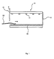
- Fig. 1 an embodiment of a continuous furnace 10 according to the invention is shown, which has a furnace housing in which as transport means 30 for workpieces 20 preferably a roller conveyor is provided.
- transport means 30 for workpieces 20 preferably a roller conveyor is provided.
- the workpieces 20 are deposited on the roller conveyor and moved by the driven rollers through the continuous furnace 10.
- any other transport means may be provided.
- the workpieces can be any components in which other material properties are desired in one end region than in the opposite end region.
- it may be the B-pillar or a molding for the B-pillar of a motor vehicle, in which the foot of the B-pillar should be relatively ductile, while the rest of the component should have a higher strength.
- the housing of the furnace 10 is preferably closed and has only an inlet and an outlet opening, can be introduced through the workpieces 20 on one side in the oven and on another side again out of it can be moved.
- the openings are each closed with covers 12 and 13.
- the covers may be, for example, oven slides, which can be pushed in front of the openings to temporarily close or release them.
- the oven slides are moved by a controllable drive.
- the covers 12 and 13 move upwardly to release the respective oven opening so that a workpiece can be moved into the oven, for example on a roller conveyor.
- the workpieces 20 can also be stored manually or by robots on the transport device.
- the workpieces can be transported on a further transport device to the furnace 10 and transferred to the transport device 30 of the furnace.
- the covers 12 and 13 may also release the respective oven opening by sideways movement, or the covers move downwardly to release the upper portion of an opening. This is advantageous, for example, if a conveyor is provided as a transport device, which moves workpieces hanging through the oven. In a suspended transport, the suspensions should be arranged so that the front end of a workpiece can protrude from the furnace while the remainder is still inside the furnace.
- At least the cover 13 at the outlet opening of the furnace 10 release different degrees of opening.
- the cover 13 can be controlled by a drive so that it completely or only partially releases the outlet opening.
- the covers can only be opened as far as necessary, which prevents unnecessary heat loss.
- heating means 11 are arranged, with which the workpieces 20 can be heated when passing through the furnace on the conveyor.
- Such heating means are known from the prior art and will not be explained in detail.
- all other required components for operating the furnace are not the subject of the invention and can be selected by the skilled person suitable.
- Fig. 1 opens the cover 12 of the input opening and a workpiece 20 is moved by the transport device 30 in the oven
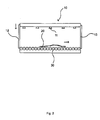
- Fig. 2 If the cover 12 is already closed again and the workpiece 20 moves on the transport device 30 through the heating path of the furnace, which is formed by the heating means 11.
- the workpiece 20 is heated to a temperature which is expediently below the hardening temperature of the material of the workpiece 20.
- the heating means 11 and the passage time of the leading edge of the workpiece 20 are selected by the heating path so that the workpiece 20 is heated to a temperature of 700 ° C.
- the length of the furnace 10 and the transport speed of the transport means 30 is selected accordingly so that the workpiece is moved continuously through the furnace and has set the desired temperature in the workpiece, as soon as the leading edge of the workpiece 20, the heating line completely to the end has passed through the furnace.
- it may also be provided to temporarily increase the movement of the transport device interrupt to keep the workpiece within the heating distance for a certain period of time.
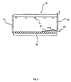
- the cover 13 releases the exit opening of the furnace 10, so that a part of the workpiece can be moved out of the furnace.
- the cover 13 does not have to be completely opened for this purpose, but can for example only release the lower region of the outlet opening, as shown in FIG Fig. 3 is shown.
- the movement of the transport device 30 is interrupted for a certain period of time. Outside the furnace 10 holding devices may be provided which support the workpiece 20.
- this portion 21 is heated to a temperature above 700 ° C, while the second portion 22 of the workpiece outside the furnace is not further heated. In both subsections, different temperatures thus occur due to the different residence time of the regions in the furnace.
- the second portion 22 outside the furnace 10 cools slightly, so that it must have previously been heated in the oven to a temperature at which, despite slight cooling at the end of the process, a temperature T 1 adjusts the material only a partial structural change, so that this area remains relatively ductile in the subsequent rapid quenching.
- a higher temperature T 2 is set by the longer heating within the heating section, which causes a complete structural change and thus austenitization.
- higher strengths thus arise in this first region. In principle, however, no complete microstructure change has to take place in this area either.
- the Temperature and thus the degree of structural change should only be higher than in the second portion 21 in order to achieve the desired differences in the material properties.
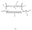
- the workpiece 20 can be removed from the furnace, as shown in FIG Fig. 4 is shown.
- the cover 13 can be further raised to increase the degree of opening, so that the workpiece 20 can be completely removed.
- the workpiece is now outside the furnace 10 with the desired temperatures T 1 and T 2 and can be supplied to further process steps. For example, it can be fed manually or by robotics to a quench bath or a forming press.
- the entire workpiece is heated in the oven to a temperature corresponding to the hardening temperature of the respective material.
- the second subarea 22 of the workpiece cools to a temperature below the hardening temperature, while the first subarea 21 of the workpiece within the furnace is kept at the hardening temperature. Even so, different temperatures occur in both subareas.
- the method according to the invention can also be carried out with a transport device 30 which moves workpieces only through a heating section enclosed by a housing, in which the heating means is arranged.
- a transport device 30 which moves workpieces only through a heating section enclosed by a housing, in which the heating means is arranged.
- a heating section enclosed by a housing, in which the heating means is arranged.
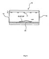
- Fig. 5 shown. In this case, it is not a closed oven, but by separating slide 12 and 13, only the region of a heating section is defined in which takes place at the transport means 30 heating by heating means 11.
- the cycle times of the respective covers 12 and 13 are adapted to the residence time of the workpiece 20 in the oven, to the speed of the transport device 30 and also to the period of standstill of the transport device 30.
- the different degrees of opening, in particular the cover 13 at the Exit opening are also adapted to the steps in the inventive method.
- the cover 13 of the outlet opening of the furnace 10 opens and then the movement of the transport device 30 is interrupted. After that, the cover 13 may possibly also slightly lower again.
- the cover 13 must open again. Simultaneously with this, the cover 12 can release the input opening to receive another workpiece. With this procedure, cycle times of 15 seconds can be achieved for the heating of workpieces.
- no continuous furnace is provided for heating the workpieces, but a furnace has only one opening through which workpieces are inserted and removed again.
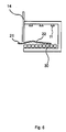
- This design of a furnace is shown schematically in FIG Fig. 6 shown.
- a workpiece is stored in the oven 10 and optionally moved with a transport device 30 into the interior of the furnace.
- the cover 14 at least partially releases the furnace opening and the workpiece 20 is moved out of the oven so far that a first portion 21 is still within the furnace, while a second portion 22 is outside the furnace. In this position, the workpiece is held until the first portion 21 has been further heated to the desired temperature. Subsequently, the workpiece 20 is completely removed from the oven and the next workpiece can be treated.
- Fig. 7 illustrated by way of example in a schematic plan view.
- three workpieces 20, 20 'and 20 are moved side by side on a transport device 30 through an oven, and at the end of the oven also portions of all workpieces protrude out of the oven to further heat the respective other sections of the workpieces within the oven is it further, that one or more workpieces are moved on a workpiece carrier through the oven.
- the workpieces are deposited on the roller conveyor 30 and simultaneously moved side by side by the driven rollers through the continuous furnace 10.
- any other transport means may be provided.
- a separate transport device can be provided for each workpiece and the movements of these transport devices can be controlled separately from one another.
- a plurality of roller conveyors can be arranged next to one another, with one workpiece being deposited on each roller conveyor.
- Fig. 9 If the cover 12 is already closed again and the workpieces 20, 20 'and 20 "move simultaneously on the transport device 30 through the heating path of the furnace, which is formed by the heating means 11. In this case, a heating of the workpieces 20, 20' and 20th "to a temperature which is below the hardening temperature of the material of the workpiece 20. If the hardening temperature of the workpiece, for example, at about 700 ° C, the heating means 11 and the lead time of the front edges of the workpieces 20, 20 'and 20 "are selected by the heating so that the workpieces 20, 20' and 20" on a Heat the temperature below 700 ° C.
- the transport movement of at least one of the workpieces is temporarily interrupted If a separate transport device is used for each workpiece, this can be done simply by temporarily interrupting the movement of the relevant transport device. If a common transport device for all workpieces is used, a temporary Interruption of the transport movement of individual workpieces by the temporary decoupling of the respective workpiece carried by the transport device.
- the decoupling can be realized in different ways depending on the embodiment of the transport device.
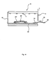
- Out Fig. 10 For example, it can be seen how two of the workpieces 20 'and 20 "are temporarily decoupled from the conveyor 30 by being lifted by plungers 40 and 41 so that they no longer contact the conveyor 30. In other types of conveyors than a roller conveyor For example, decoupling may be accomplished by unlatching workpieces from a transport device into which they have been previously hung.
- the plungers 40 and 41 are located below the workpieces and perform a clocked up and down movement, which is controlled by a control device.
- the plunger can be guided by gaps between the individual rollers of the roller conveyor and so one or more workpieces clocked raise and lower again.
- two workpieces 20 'and 20 "are decoupled from the roller conveyor while a remaining workpiece 20 is moved on, but the invention is not limited to this embodiment but, for example, two workpieces can be moved while only one workpiece is decoupled, or other number of workpieces other variations are possible.
- the cover 13 releases the exit opening of the furnace 10, so that a part of the further moving workpiece 20 can be moved out of the furnace.
- the movement of the transport device 30 is interrupted for a certain period of time, for example 15-25 seconds, for this workpiece 20.
- the workpiece 20 can be removed from the furnace, as shown in FIG Fig. 11 is shown. Subsequently or already while the first workpiece 20 is being driven out of the oven, the transport movement of at least one of the remaining workpieces 20 'resumed. In the embodiment of Fig. 11 the respective workpiece 20 'is again coupled to the transport device 30 by the associated plunger perform a downward movement and settle the workpiece again on the transport device 30, which transports it to the furnace exit.
- the cycle times of the respective covers 12 and 13 are adapted to the residence time of the workpiece 20 in the oven, to the speed of the transport device 30 and also to the period of standstill of the transport device 30.
- the upward and downward movement of the plungers is also adapted to these parameters, wherein the actuation of all components preferably takes place by means of a common control device.
- FIGURE 11 is a top view of how three workpieces 20, 20 'and 20 "are heated by the oven 10.
- the workpieces were previously placed side-by-side on the roller conveyor 30 and moved through the oven to above rams 40, 41, 42 , 43, 44 and 45, wherein for decoupling of each workpiece there are for example two plungers each which can raise and lower a workpiece at two points, the plungers being arranged in spaces between the individual rollers of the roller conveyor, so that they are arranged between the rollers Rolls can be pulled out Fig. 14 the activated plungers 40 and 41 are shown filled in black, wherein these activated plungers have lifted the workpiece 20 "and thus decoupled it from the movement of the roller conveyor 30.
- the currently not activated plungers 42, 43, 44 and 45 are white. This applies to the associated plunger of the workpiece 20, which has already been removed from the oven and for the associated plunger 42 and 43 of the workpiece 20 ', which currently undergoes a partial continuation of the heating at the end of the furnace.
- sensors may be provided within the furnace, which determine the position of the workpieces on the transport device 30 and transmit to a control device which performs a suitably adapted control of the upward and downward movement of the plunger.
- the plungers can be designed in different ways to safely lift and lower workpieces.
Landscapes
- Engineering & Computer Science (AREA)
- Chemical & Material Sciences (AREA)
- Mechanical Engineering (AREA)
- General Engineering & Computer Science (AREA)
- Crystallography & Structural Chemistry (AREA)
- Thermal Sciences (AREA)
- Physics & Mathematics (AREA)
- Materials Engineering (AREA)
- Metallurgy (AREA)
- Organic Chemistry (AREA)
- Heat Treatments In General, Especially Conveying And Cooling (AREA)
- Heat Treatment Of Articles (AREA)
- Tunnel Furnaces (AREA)
Applications Claiming Priority (2)
| Application Number | Priority Date | Filing Date | Title |
|---|---|---|---|
| DE102008019471 | 2008-04-17 | ||
| DE102008055980A DE102008055980A1 (de) | 2008-04-17 | 2008-11-05 | Verfahren und Durchlaufofen zum Erwärmen von Werkstücken |
Publications (3)
| Publication Number | Publication Date |
|---|---|
| EP2110448A2 true EP2110448A2 (fr) | 2009-10-21 |
| EP2110448A3 EP2110448A3 (fr) | 2013-02-13 |
| EP2110448B1 EP2110448B1 (fr) | 2018-10-24 |
Family
ID=40902112
Family Applications (1)
| Application Number | Title | Priority Date | Filing Date |
|---|---|---|---|
| EP09005231.7A Active EP2110448B1 (fr) | 2008-04-17 | 2009-04-09 | Procédé et four à passage continu destinés au chauffage de pièces à usiner |
Country Status (4)
| Country | Link |
|---|---|
| US (1) | US8529250B2 (fr) |
| EP (1) | EP2110448B1 (fr) |
| DE (1) | DE102008055980A1 (fr) |
| ES (1) | ES2707225T3 (fr) |
Cited By (6)
| Publication number | Priority date | Publication date | Assignee | Title |
|---|---|---|---|---|
| WO2010089103A1 (fr) | 2009-02-03 | 2010-08-12 | Magna Ihv Gesellschaft Für Innenhochdruckverfahren Mbh | Procédé et four pour obtenir une pièce à travailler métallique avec des régions de ductilité différente |
| EP2336374A1 (fr) * | 2009-12-16 | 2011-06-22 | Schwartz, Eva | Procédé et dispositif destinés au chauffage et au refroidissement partiel de pièces usinées dans un four à passage continu |
| EP2365100A2 (fr) * | 2010-03-04 | 2011-09-14 | Kirchhoff Automotive Deutschland GmbH | Procédé pour produine une piece moulee ayant au moins deux domaines de structure avec des ductilites differentes |
| DE102011114764A1 (de) | 2011-10-01 | 2013-04-04 | Volkswagen Aktiengesellschaft | Verfahren zur Herstellung formgehärteter Bauteile und Durchlaufofen zum Erwärmen einer zum Formhärten vorgesehenen Platine |
| WO2014173703A1 (fr) * | 2013-04-25 | 2014-10-30 | N. Bättenhausen Indrustrielle Wärme- Und Elektrorechnik Gmbh | Dispositif de trempe sous presse d'éléments structuraux |
| DE102020128925A1 (de) | 2020-11-03 | 2022-05-05 | Audi Aktiengesellschaft | Verfahren und Anlage zum Abschrecken von Metallbauteilen |
Families Citing this family (12)
| Publication number | Priority date | Publication date | Assignee | Title |
|---|---|---|---|---|
| US20110059412A1 (en) * | 2009-09-09 | 2011-03-10 | Thomas Robert Wiedemeier | Device and process for eradicating pests in wood |
| DE102012001742A1 (de) * | 2012-01-28 | 2013-08-01 | Volkswagen Aktiengesellschaft | Vorrichtung zum Erwärmen von Blechwerkstücken für ein nachfolgendes Warmumformen und insbesondere Presshärten |
| DE102012103275A1 (de) * | 2012-04-16 | 2013-10-17 | Benteler Automobiltechnik Gmbh | Schichtofenanlage sowie Verfahren zum Betreiben der Schichtofenanlage |
| US10625323B2 (en) * | 2016-02-19 | 2020-04-21 | Ford Global Technologies, Llc | Method for monitoring quality of hot stamped components |
| US10335845B2 (en) | 2016-04-20 | 2019-07-02 | Ford Global Technologies, Llc | Hot-stamping furnace and method of hot stamping |
| US10350664B2 (en) | 2016-06-30 | 2019-07-16 | Ford Global Technologies, Llc | Furnace assembly and method for hot-stamping vehicle components |
| EP3559283A1 (fr) * | 2016-12-22 | 2019-10-30 | Autotech Engineering S.L. | Procédé de chauffage d'une pièce brute et système de chauffage |
| CN107837993B (zh) * | 2017-10-11 | 2021-03-02 | 盐城丰东特种炉业有限公司 | 连续式工件涂胶固化工艺 |
| DE102019004618A1 (de) * | 2019-06-26 | 2020-12-31 | Bsn Thermprozesstechnik Gmbh | Rollenherd-Durchlauf-Ofenanlage und Verfahren zur Erwärmung von mit Aluminium, Silizium und/oder Zink beschichteten Stahlplatinen auf Härte- und Presstemperatur |
| DE102020116593A1 (de) | 2020-06-24 | 2021-12-30 | AICHELIN Holding GmbH | Wärmebehandlungsanlage und Verfahren zur Herstellung von Formbauteilen |
| DE102020129506A1 (de) | 2020-11-09 | 2022-05-12 | Ebner Industrieofenbau Gmbh | Zentrierungsvorrichtung für Metallplatinen |
| DE102022108513A1 (de) * | 2021-04-16 | 2022-10-20 | Aerospace Transmission Technologies GmbH | Steuereinrichtung und Verfahren zur Steuerung einer Anlage und eines Prozesses zur Wärmebehandlung von metallischen Werkstücken |
Citations (2)
| Publication number | Priority date | Publication date | Assignee | Title |
|---|---|---|---|---|
| DE20014361U1 (de) | 2000-08-19 | 2000-10-12 | Benteler Werke Ag | B-Säule für ein Kraftfahrzeug |
| EP1426454A1 (fr) | 2002-12-03 | 2004-06-09 | Benteler Automobiltechnik GmbH | Procédé de fabrication d'une piéce de forme avec au moins deux régions de structure de ductilité differente et four continu associé |
Family Cites Families (13)
| Publication number | Priority date | Publication date | Assignee | Title |
|---|---|---|---|---|
| US4013403A (en) * | 1975-12-08 | 1977-03-22 | Pullman Incorporated | Support means for a roller hearth in a kiln |
| DE2642099C3 (de) * | 1976-09-18 | 1981-12-17 | Aeg-Elotherm Gmbh, 5630 Remscheid | Durchlaufinduktionsofenanlage zum Erwärmen von metallischen Werkstücken |
| IT1085472B (it) * | 1977-07-28 | 1985-05-28 | Siti | Apparecchiatura e procedimento per lo scarico di forni per la produzione di piastrelle |
| US4554437A (en) * | 1984-05-17 | 1985-11-19 | Pet Incorporated | Tunnel oven |
| US5201401A (en) * | 1989-10-31 | 1993-04-13 | Sms Hasenclever Gmbh | Discharge conveying apparatus for an extrusion press |
| DE4034653A1 (de) * | 1990-10-31 | 1992-05-07 | Loi Ind Ofenanlagen | Verfahren und durchstossofen zum waermebehandeln von werkstuecken |
| JP4480231B2 (ja) * | 2000-05-30 | 2010-06-16 | トーヨーユニバーサル株式会社 | 金属製ワークピースのコンベクション式ろう付け方法およびその装置 |
| DE10314115A1 (de) * | 2003-03-28 | 2004-10-14 | Audi Ag | Verfahren zur Umformung einer Platine aus einem Vergütungsstahl und Vorrichtung zur Durchführung des Verfahrens |
| US8087407B2 (en) * | 2004-03-23 | 2012-01-03 | Middleby Corporation | Conveyor oven apparatus and method |
| EP1647789A1 (fr) * | 2004-10-04 | 2006-04-19 | Ngk Insulators, Ltd. | Four continu pour le traitement thermique et procédé de traitement thermique |
| US7340992B1 (en) * | 2005-01-27 | 2008-03-11 | Wolfe Electric, Inc. | Dual belt conveyor oven |
| DE102008030279A1 (de) * | 2008-06-30 | 2010-01-07 | Benteler Automobiltechnik Gmbh | Partielles Warmformen und Härten mittels Infrarotlampenerwärmung |
| DE102010010156A1 (de) * | 2010-03-04 | 2011-09-08 | Kirchhoff Automotive Deutschland Gmbh | Verfahren zur Herstellung eines Formteiles mit mindestens zwei Gefügebereichen unterschiedlicher Duktilität |
-
2008
- 2008-11-05 DE DE102008055980A patent/DE102008055980A1/de not_active Ceased
-
2009
- 2009-04-09 EP EP09005231.7A patent/EP2110448B1/fr active Active
- 2009-04-09 ES ES09005231T patent/ES2707225T3/es active Active
- 2009-04-13 US US12/422,611 patent/US8529250B2/en active Active
Patent Citations (2)
| Publication number | Priority date | Publication date | Assignee | Title |
|---|---|---|---|---|
| DE20014361U1 (de) | 2000-08-19 | 2000-10-12 | Benteler Werke Ag | B-Säule für ein Kraftfahrzeug |
| EP1426454A1 (fr) | 2002-12-03 | 2004-06-09 | Benteler Automobiltechnik GmbH | Procédé de fabrication d'une piéce de forme avec au moins deux régions de structure de ductilité differente et four continu associé |
Cited By (10)
| Publication number | Priority date | Publication date | Assignee | Title |
|---|---|---|---|---|
| WO2010089103A1 (fr) | 2009-02-03 | 2010-08-12 | Magna Ihv Gesellschaft Für Innenhochdruckverfahren Mbh | Procédé et four pour obtenir une pièce à travailler métallique avec des régions de ductilité différente |
| EP2336374A1 (fr) * | 2009-12-16 | 2011-06-22 | Schwartz, Eva | Procédé et dispositif destinés au chauffage et au refroidissement partiel de pièces usinées dans un four à passage continu |
| WO2011082934A1 (fr) * | 2009-12-16 | 2011-07-14 | Schwartz, Eva | Procédé et dispositif pour chauffer et refroidir partiellement des pièces dans un four continu |
| EP2365100A2 (fr) * | 2010-03-04 | 2011-09-14 | Kirchhoff Automotive Deutschland GmbH | Procédé pour produine une piece moulee ayant au moins deux domaines de structure avec des ductilites differentes |
| EP2365100A3 (fr) * | 2010-03-04 | 2014-02-19 | Kirchhoff Automotive Deutschland GmbH | Procédé pour produine une piece moulee ayant au moins deux domaines de structure avec des ductilites differentes |
| DE102011114764A1 (de) | 2011-10-01 | 2013-04-04 | Volkswagen Aktiengesellschaft | Verfahren zur Herstellung formgehärteter Bauteile und Durchlaufofen zum Erwärmen einer zum Formhärten vorgesehenen Platine |
| DE102011114764B4 (de) * | 2011-10-01 | 2016-04-21 | Volkswagen Aktiengesellschaft | Verfahren zur Herstellung formgehärteter Bauteile und Durchlaufofen zum Erwärmen einer zum Formhärten vorgesehenen Platine |
| WO2014173703A1 (fr) * | 2013-04-25 | 2014-10-30 | N. Bättenhausen Indrustrielle Wärme- Und Elektrorechnik Gmbh | Dispositif de trempe sous presse d'éléments structuraux |
| US10590500B2 (en) | 2013-04-25 | 2020-03-17 | N. Bättenhausen Industrielle Wärme- und Elektrotechnik GmbH | Apparatus for the press hardening of components |
| DE102020128925A1 (de) | 2020-11-03 | 2022-05-05 | Audi Aktiengesellschaft | Verfahren und Anlage zum Abschrecken von Metallbauteilen |
Also Published As
| Publication number | Publication date |
|---|---|
| US20090263758A1 (en) | 2009-10-22 |
| EP2110448A3 (fr) | 2013-02-13 |
| DE102008055980A1 (de) | 2009-10-29 |
| EP2110448B1 (fr) | 2018-10-24 |
| US8529250B2 (en) | 2013-09-10 |
| ES2707225T3 (es) | 2019-04-03 |
Similar Documents
| Publication | Publication Date | Title |
|---|---|---|
| EP2110448B1 (fr) | Procédé et four à passage continu destinés au chauffage de pièces à usiner | |
| EP2365100B1 (fr) | Procédé et dispositif pour produine une piece moulee ayant au moins deux domaines de structure avec des ductilites differentes | |
| DE102005032113B3 (de) | Verfahren und Vorrichtung zum Warmumformen und partiellen Härten eines Bauteils | |
| EP2993241B1 (fr) | Procede et presse pour fabriquer au moins en partie des composants de tole durcis | |
| DE102009015013B4 (de) | Verfahren zum Herstellen partiell gehärteter Stahlbauteile | |
| EP2233593B1 (fr) | Procédé et station de déformage à chaud pour la fabrication de composants de formage en tôle d'acier durcis par presse | |
| EP3172345B1 (fr) | Procédé de chauffage de tôles d'acier | |
| DE102007012180B3 (de) | Verfahren zur Wärmebehandlung von Halbzeugen aus Metall | |
| EP1426454A1 (fr) | Procédé de fabrication d'une piéce de forme avec au moins deux régions de structure de ductilité differente et four continu associé | |
| EP2864506B1 (fr) | Procédé et dispositif de fabrication d'un composant métallique trempé à la presse | |
| EP1954997B1 (fr) | Procede et dispositif de chauffage de composants en acier dans un four continu | |
| DE102005055494B3 (de) | Verfahren zum Herstellen von einem Bauteil aus einem metallischen Flachprodukt durch Pressumformen | |
| EP2548975A1 (fr) | Procédé et dispositif de fabrication d'un composant métallique durci doté d'au moins deux zones ayant une ductilité différente | |
| WO2010048951A1 (fr) | Procédé et dispositif de régulation de température d'un corps de tôle d'acier | |
| DE112017002311T5 (de) | Warmform-Werkzeug mit Infrarot-Lichtquelle | |
| EP2730346B2 (fr) | Ligne moulée à chaud pour la fabrication de produits de tôle d'acier moulés à chaud et durcis à la presse | |
| DE102011114764B4 (de) | Verfahren zur Herstellung formgehärteter Bauteile und Durchlaufofen zum Erwärmen einer zum Formhärten vorgesehenen Platine | |
| DE102012012518A1 (de) | Warmumformwerkzeug zur Herstellung von Formteilen | |
| EP2883967B1 (fr) | Procédé et dispositif de post-traitement d'un élément de formage métallique durci au moyen du chauffage par résistance électrique | |
| EP3408416B1 (fr) | Procédé de traitement thermique et dispositif de traitement thermique | |
| DE102017109613B3 (de) | Warmformlinie mit Temperierstation sowie Verfahren zum Betreiben | |
| WO2011082934A1 (fr) | Procédé et dispositif pour chauffer et refroidir partiellement des pièces dans un four continu | |
| EP3420111B1 (fr) | Procédé de traitement thermique ciblé sur les zones d'une pièce | |
| EP2439289B1 (fr) | Procédé et four destinés au traitement de pièces à usiner | |
| WO2023284905A1 (fr) | Procédé de chauffage multizone, appareil de chauffage et procédé de production d'un composant de véhicule automobile |
Legal Events
| Date | Code | Title | Description |
|---|---|---|---|
| PUAI | Public reference made under article 153(3) epc to a published international application that has entered the european phase |
Free format text: ORIGINAL CODE: 0009012 |
|
| AK | Designated contracting states |
Kind code of ref document: A2 Designated state(s): AT BE BG CH CY CZ DE DK EE ES FI FR GB GR HR HU IE IS IT LI LT LU LV MC MK MT NL NO PL PT RO SE SI SK TR |
|
| RAP1 | Party data changed (applicant data changed or rights of an application transferred) |
Owner name: SCHWARTZ, EVA |
|
| PUAL | Search report despatched |
Free format text: ORIGINAL CODE: 0009013 |
|
| AK | Designated contracting states |
Kind code of ref document: A3 Designated state(s): AT BE BG CH CY CZ DE DK EE ES FI FR GB GR HR HU IE IS IT LI LT LU LV MC MK MT NL NO PL PT RO SE SI SK TR |
|
| AX | Request for extension of the european patent |
Extension state: AL BA RS |
|
| RIC1 | Information provided on ipc code assigned before grant |
Ipc: F27B 9/30 20060101ALI20130104BHEP Ipc: F27B 9/02 20060101ALI20130104BHEP Ipc: C21D 9/00 20060101AFI20130104BHEP Ipc: B62D 25/04 20060101ALI20130104BHEP Ipc: B21J 1/06 20060101ALI20130104BHEP Ipc: F27B 9/24 20060101ALI20130104BHEP |
|
| RAP1 | Party data changed (applicant data changed or rights of an application transferred) |
Owner name: SCHWARTZ, EVA |
|
| 17P | Request for examination filed |
Effective date: 20130813 |
|
| RBV | Designated contracting states (corrected) |
Designated state(s): AT BE BG CH CY CZ DE DK EE ES FI FR GB GR HR HU IE IS IT LI LT LU LV MC MK MT NL NO PL PT RO SE SI SK TR |
|
| RAP1 | Party data changed (applicant data changed or rights of an application transferred) |
Owner name: SCHWARTZ GMBH |
|
| 17Q | First examination report despatched |
Effective date: 20160217 |
|
| STAA | Information on the status of an ep patent application or granted ep patent |
Free format text: STATUS: EXAMINATION IS IN PROGRESS |
|
| GRAP | Despatch of communication of intention to grant a patent |
Free format text: ORIGINAL CODE: EPIDOSNIGR1 |
|
| STAA | Information on the status of an ep patent application or granted ep patent |
Free format text: STATUS: GRANT OF PATENT IS INTENDED |
|
| INTG | Intention to grant announced |
Effective date: 20180731 |
|
| GRAS | Grant fee paid |
Free format text: ORIGINAL CODE: EPIDOSNIGR3 |
|
| GRAA | (expected) grant |
Free format text: ORIGINAL CODE: 0009210 |
|
| STAA | Information on the status of an ep patent application or granted ep patent |
Free format text: STATUS: THE PATENT HAS BEEN GRANTED |
|
| AK | Designated contracting states |
Kind code of ref document: B1 Designated state(s): AT BE BG CH CY CZ DE DK EE ES FI FR GB GR HR HU IE IS IT LI LT LU LV MC MK MT NL NO PL PT RO SE SI SK TR |
|
| REG | Reference to a national code |
Ref country code: GB Ref legal event code: FG4D Free format text: NOT ENGLISH |
|
| REG | Reference to a national code |
Ref country code: CH Ref legal event code: EP |
|
| REG | Reference to a national code |
Ref country code: IE Ref legal event code: FG4D Free format text: LANGUAGE OF EP DOCUMENT: GERMAN |
|
| REG | Reference to a national code |
Ref country code: AT Ref legal event code: REF Ref document number: 1056730 Country of ref document: AT Kind code of ref document: T Effective date: 20181115 |
|
| REG | Reference to a national code |
Ref country code: DE Ref legal event code: R096 Ref document number: 502009015389 Country of ref document: DE |
|
| REG | Reference to a national code |
Ref country code: SE Ref legal event code: TRGR |
|
| REG | Reference to a national code |
Ref country code: NL Ref legal event code: MP Effective date: 20181024 |
|
| REG | Reference to a national code |
Ref country code: LT Ref legal event code: MG4D |
|
| PG25 | Lapsed in a contracting state [announced via postgrant information from national office to epo] |
Ref country code: NL Free format text: LAPSE BECAUSE OF FAILURE TO SUBMIT A TRANSLATION OF THE DESCRIPTION OR TO PAY THE FEE WITHIN THE PRESCRIBED TIME-LIMIT Effective date: 20181024 |
|
| REG | Reference to a national code |
Ref country code: ES Ref legal event code: FG2A Ref document number: 2707225 Country of ref document: ES Kind code of ref document: T3 Effective date: 20190403 |
|
| PG25 | Lapsed in a contracting state [announced via postgrant information from national office to epo] |
Ref country code: LV Free format text: LAPSE BECAUSE OF FAILURE TO SUBMIT A TRANSLATION OF THE DESCRIPTION OR TO PAY THE FEE WITHIN THE PRESCRIBED TIME-LIMIT Effective date: 20181024 Ref country code: LT Free format text: LAPSE BECAUSE OF FAILURE TO SUBMIT A TRANSLATION OF THE DESCRIPTION OR TO PAY THE FEE WITHIN THE PRESCRIBED TIME-LIMIT Effective date: 20181024 Ref country code: NO Free format text: LAPSE BECAUSE OF FAILURE TO SUBMIT A TRANSLATION OF THE DESCRIPTION OR TO PAY THE FEE WITHIN THE PRESCRIBED TIME-LIMIT Effective date: 20190124 Ref country code: FI Free format text: LAPSE BECAUSE OF FAILURE TO SUBMIT A TRANSLATION OF THE DESCRIPTION OR TO PAY THE FEE WITHIN THE PRESCRIBED TIME-LIMIT Effective date: 20181024 Ref country code: IS Free format text: LAPSE BECAUSE OF FAILURE TO SUBMIT A TRANSLATION OF THE DESCRIPTION OR TO PAY THE FEE WITHIN THE PRESCRIBED TIME-LIMIT Effective date: 20190224 Ref country code: BG Free format text: LAPSE BECAUSE OF FAILURE TO SUBMIT A TRANSLATION OF THE DESCRIPTION OR TO PAY THE FEE WITHIN THE PRESCRIBED TIME-LIMIT Effective date: 20190124 Ref country code: HR Free format text: LAPSE BECAUSE OF FAILURE TO SUBMIT A TRANSLATION OF THE DESCRIPTION OR TO PAY THE FEE WITHIN THE PRESCRIBED TIME-LIMIT Effective date: 20181024 Ref country code: PL Free format text: LAPSE BECAUSE OF FAILURE TO SUBMIT A TRANSLATION OF THE DESCRIPTION OR TO PAY THE FEE WITHIN THE PRESCRIBED TIME-LIMIT Effective date: 20181024 |
|
| PG25 | Lapsed in a contracting state [announced via postgrant information from national office to epo] |
Ref country code: GR Free format text: LAPSE BECAUSE OF FAILURE TO SUBMIT A TRANSLATION OF THE DESCRIPTION OR TO PAY THE FEE WITHIN THE PRESCRIBED TIME-LIMIT Effective date: 20190125 Ref country code: PT Free format text: LAPSE BECAUSE OF FAILURE TO SUBMIT A TRANSLATION OF THE DESCRIPTION OR TO PAY THE FEE WITHIN THE PRESCRIBED TIME-LIMIT Effective date: 20190224 |
|
| REG | Reference to a national code |
Ref country code: DE Ref legal event code: R097 Ref document number: 502009015389 Country of ref document: DE |
|
| PG25 | Lapsed in a contracting state [announced via postgrant information from national office to epo] |
Ref country code: DK Free format text: LAPSE BECAUSE OF FAILURE TO SUBMIT A TRANSLATION OF THE DESCRIPTION OR TO PAY THE FEE WITHIN THE PRESCRIBED TIME-LIMIT Effective date: 20181024 Ref country code: IT Free format text: LAPSE BECAUSE OF FAILURE TO SUBMIT A TRANSLATION OF THE DESCRIPTION OR TO PAY THE FEE WITHIN THE PRESCRIBED TIME-LIMIT Effective date: 20181024 |
|
| PG25 | Lapsed in a contracting state [announced via postgrant information from national office to epo] |
Ref country code: RO Free format text: LAPSE BECAUSE OF FAILURE TO SUBMIT A TRANSLATION OF THE DESCRIPTION OR TO PAY THE FEE WITHIN THE PRESCRIBED TIME-LIMIT Effective date: 20181024 Ref country code: EE Free format text: LAPSE BECAUSE OF FAILURE TO SUBMIT A TRANSLATION OF THE DESCRIPTION OR TO PAY THE FEE WITHIN THE PRESCRIBED TIME-LIMIT Effective date: 20181024 Ref country code: SK Free format text: LAPSE BECAUSE OF FAILURE TO SUBMIT A TRANSLATION OF THE DESCRIPTION OR TO PAY THE FEE WITHIN THE PRESCRIBED TIME-LIMIT Effective date: 20181024 |
|
| PLBE | No opposition filed within time limit |
Free format text: ORIGINAL CODE: 0009261 |
|
| STAA | Information on the status of an ep patent application or granted ep patent |
Free format text: STATUS: NO OPPOSITION FILED WITHIN TIME LIMIT |
|
| 26N | No opposition filed |
Effective date: 20190725 |
|
| PG25 | Lapsed in a contracting state [announced via postgrant information from national office to epo] |
Ref country code: SI Free format text: LAPSE BECAUSE OF FAILURE TO SUBMIT A TRANSLATION OF THE DESCRIPTION OR TO PAY THE FEE WITHIN THE PRESCRIBED TIME-LIMIT Effective date: 20181024 |
|
| REG | Reference to a national code |
Ref country code: CH Ref legal event code: PL |
|
| REG | Reference to a national code |
Ref country code: BE Ref legal event code: MM Effective date: 20190430 |
|
| GBPC | Gb: european patent ceased through non-payment of renewal fee |
Effective date: 20190409 |
|
| PG25 | Lapsed in a contracting state [announced via postgrant information from national office to epo] |
Ref country code: LU Free format text: LAPSE BECAUSE OF NON-PAYMENT OF DUE FEES Effective date: 20190409 Ref country code: MC Free format text: LAPSE BECAUSE OF FAILURE TO SUBMIT A TRANSLATION OF THE DESCRIPTION OR TO PAY THE FEE WITHIN THE PRESCRIBED TIME-LIMIT Effective date: 20181024 |
|
| PG25 | Lapsed in a contracting state [announced via postgrant information from national office to epo] |
Ref country code: CH Free format text: LAPSE BECAUSE OF NON-PAYMENT OF DUE FEES Effective date: 20190430 Ref country code: GB Free format text: LAPSE BECAUSE OF NON-PAYMENT OF DUE FEES Effective date: 20190409 Ref country code: LI Free format text: LAPSE BECAUSE OF NON-PAYMENT OF DUE FEES Effective date: 20190430 |
|
| PG25 | Lapsed in a contracting state [announced via postgrant information from national office to epo] |
Ref country code: FR Free format text: LAPSE BECAUSE OF NON-PAYMENT OF DUE FEES Effective date: 20190430 Ref country code: BE Free format text: LAPSE BECAUSE OF NON-PAYMENT OF DUE FEES Effective date: 20190430 |
|
| PG25 | Lapsed in a contracting state [announced via postgrant information from national office to epo] |
Ref country code: TR Free format text: LAPSE BECAUSE OF FAILURE TO SUBMIT A TRANSLATION OF THE DESCRIPTION OR TO PAY THE FEE WITHIN THE PRESCRIBED TIME-LIMIT Effective date: 20181024 |
|
| PG25 | Lapsed in a contracting state [announced via postgrant information from national office to epo] |
Ref country code: IE Free format text: LAPSE BECAUSE OF NON-PAYMENT OF DUE FEES Effective date: 20190409 |
|
| PG25 | Lapsed in a contracting state [announced via postgrant information from national office to epo] |
Ref country code: CY Free format text: LAPSE BECAUSE OF FAILURE TO SUBMIT A TRANSLATION OF THE DESCRIPTION OR TO PAY THE FEE WITHIN THE PRESCRIBED TIME-LIMIT Effective date: 20181024 |
|
| PG25 | Lapsed in a contracting state [announced via postgrant information from national office to epo] |
Ref country code: MT Free format text: LAPSE BECAUSE OF FAILURE TO SUBMIT A TRANSLATION OF THE DESCRIPTION OR TO PAY THE FEE WITHIN THE PRESCRIBED TIME-LIMIT Effective date: 20181024 Ref country code: HU Free format text: LAPSE BECAUSE OF FAILURE TO SUBMIT A TRANSLATION OF THE DESCRIPTION OR TO PAY THE FEE WITHIN THE PRESCRIBED TIME-LIMIT; INVALID AB INITIO Effective date: 20090409 |
|
| PG25 | Lapsed in a contracting state [announced via postgrant information from national office to epo] |
Ref country code: MK Free format text: LAPSE BECAUSE OF FAILURE TO SUBMIT A TRANSLATION OF THE DESCRIPTION OR TO PAY THE FEE WITHIN THE PRESCRIBED TIME-LIMIT Effective date: 20181024 |
|
| PGFP | Annual fee paid to national office [announced via postgrant information from national office to epo] |
Ref country code: ES Payment date: 20230627 Year of fee payment: 15 Ref country code: DE Payment date: 20230420 Year of fee payment: 15 Ref country code: CZ Payment date: 20230403 Year of fee payment: 15 |
|
| PGFP | Annual fee paid to national office [announced via postgrant information from national office to epo] |
Ref country code: SE Payment date: 20230420 Year of fee payment: 15 Ref country code: AT Payment date: 20230420 Year of fee payment: 15 |