EP2108945B1 - Vorrichtung und Verfahren zur Computer-Tomographie, welche einen Probenhalter zur Aufnahme von mehreren Proben enthalten - Google Patents
Vorrichtung und Verfahren zur Computer-Tomographie, welche einen Probenhalter zur Aufnahme von mehreren Proben enthalten Download PDFInfo
- Publication number
- EP2108945B1 EP2108945B1 EP09250908.2A EP09250908A EP2108945B1 EP 2108945 B1 EP2108945 B1 EP 2108945B1 EP 09250908 A EP09250908 A EP 09250908A EP 2108945 B1 EP2108945 B1 EP 2108945B1
- Authority
- EP
- European Patent Office
- Prior art keywords
- sample
- samples
- supports
- operative
- rails
- Prior art date
- Legal status (The legal status is an assumption and is not a legal conclusion. Google has not performed a legal analysis and makes no representation as to the accuracy of the status listed.)
- Expired - Fee Related
Links
- 238000002591 computed tomography Methods 0.000 title claims description 16
- 238000000034 method Methods 0.000 title claims description 13
- 238000007689 inspection Methods 0.000 claims description 20
- 230000007246 mechanism Effects 0.000 claims description 4
- 238000010586 diagram Methods 0.000 description 7
- 238000004458 analytical method Methods 0.000 description 3
- 230000001066 destructive effect Effects 0.000 description 2
- 239000000463 material Substances 0.000 description 2
- 229910001369 Brass Inorganic materials 0.000 description 1
- 238000003491 array Methods 0.000 description 1
- 239000010951 brass Substances 0.000 description 1
- 239000000872 buffer Substances 0.000 description 1
- 238000006073 displacement reaction Methods 0.000 description 1
- 230000006870 function Effects 0.000 description 1
- 230000003993 interaction Effects 0.000 description 1
- 239000002184 metal Substances 0.000 description 1
- 229910052751 metal Inorganic materials 0.000 description 1
- 238000012986 modification Methods 0.000 description 1
- 230000004048 modification Effects 0.000 description 1
- 230000003287 optical effect Effects 0.000 description 1
- 230000008569 process Effects 0.000 description 1
- 239000004065 semiconductor Substances 0.000 description 1
- WFKWXMTUELFFGS-UHFFFAOYSA-N tungsten Chemical compound [W] WFKWXMTUELFFGS-UHFFFAOYSA-N 0.000 description 1
- 229910052721 tungsten Inorganic materials 0.000 description 1
- 239000010937 tungsten Substances 0.000 description 1
Images


Classifications
-
- G—PHYSICS
- G01—MEASURING; TESTING
- G01N—INVESTIGATING OR ANALYSING MATERIALS BY DETERMINING THEIR CHEMICAL OR PHYSICAL PROPERTIES
- G01N23/00—Investigating or analysing materials by the use of wave or particle radiation, e.g. X-rays or neutrons, not covered by groups G01N3/00 – G01N17/00, G01N21/00 or G01N22/00
- G01N23/02—Investigating or analysing materials by the use of wave or particle radiation, e.g. X-rays or neutrons, not covered by groups G01N3/00 – G01N17/00, G01N21/00 or G01N22/00 by transmitting the radiation through the material
- G01N23/04—Investigating or analysing materials by the use of wave or particle radiation, e.g. X-rays or neutrons, not covered by groups G01N3/00 – G01N17/00, G01N21/00 or G01N22/00 by transmitting the radiation through the material and forming images of the material
- G01N23/046—Investigating or analysing materials by the use of wave or particle radiation, e.g. X-rays or neutrons, not covered by groups G01N3/00 – G01N17/00, G01N21/00 or G01N22/00 by transmitting the radiation through the material and forming images of the material using tomography, e.g. computed tomography [CT]
-
- G—PHYSICS
- G01—MEASURING; TESTING
- G01N—INVESTIGATING OR ANALYSING MATERIALS BY DETERMINING THEIR CHEMICAL OR PHYSICAL PROPERTIES
- G01N2223/00—Investigating materials by wave or particle radiation
- G01N2223/40—Imaging
- G01N2223/419—Imaging computed tomograph
Definitions
- the invention generally relates to non-destructive inspection of components.
- Computed tomography involves the use of X-rays that are passed through a sample. Based on the amount of X-ray energy detected at a detector located downstream of the sample, information about the sample can be calculated. By way of example, representations of sample shape and density in three dimensions can be determined.
- CT Computed tomography
- an exemplary embodiment of a computed tomography system for multi-sample inspection comprises: an X-ray source; a multi-sample positioning unit having multiple sample supports, each of the sample supports being located along a corresponding line of sight of the X-ray source of the system, the sample supports being operative to orient multiple samples simultaneously such that each of the multiple samples is positionable at multiple orientations; wherein the multi-sample positioning unit has a carrier operative to support the sample supports and movable to establish vertical positions of the sample supports relative to the X-ray source, and comprises a drive motor and sets of rails, each set of rails being angularly displaced with respect to adjacent sets of rails, wherein the drive motor is operable to translate the multiple sample supports laterally in unison relative to the carrier along the respective sets of rails.
- An exemplary embodiment of a method for performing computed tomography on multiple samples comprises: providing a multi-sample positioning unit having a carrier that supports a plurality of sample supports, the sample supports being operative to orient multiple samples simultaneously such that each of the multiple samples is positionable at multiple orientations, wherein the carrier is movable to establish vertical positions of the sample supports relative to an X-ray source, a drive motor, and sets of rails, each set of rails being anguiany displaced with respect to adjacent sets of rails; simultaneously directing X-rays toward multiple samples from the X-ray source; during the directing of the X-rays, reorienting the samples with respect to the X-ray source using the drive motor to translate the plurality of sample supports laterally in unison relative to the carrier along the respective sets of rails; and obtaining information corresponding to attenuation of the X-rays attributable to the multiple samples for producing computed tomography images of the samples.
- CT Computed tomography
- a multi-sample positioning unit is used to position two or more samples for simultaneous inspection.
- FIG. 1 is a schematic diagram depicting an exemplary embodiment of a system involving multi-sample inspection.
- system 100 includes an X-ray source 102, an optional pre-sample collimator 103, a sample 104 positioned on a multi-sample positioning unit 106, an optional post-sample collimator 108, an array of detectors 110, an image processor 112, and a display/analysis system 114.
- X-ray source 102 e.g., a spot source
- the X-rays are emitted as a fan-shaped beam 115.
- source 102 incorporates an integrated source collimator (not shown in FIG. 1 ) within a housing 117 in order to limit X-rays generated at the source to the fan-shaped beam.
- Multi-sample positioning unit 106 is an apparatus used for positioning multiple samples shown schematically, only one representative sample 104 being shown. In operation, multi-sample positioning unit 106 exposes various portions of each of the samples to the X-rays emitted by source 102. In this embodiment, the multi-sample positioning unit can be used to rotate sample 104 both clockwise and counterclockwise, as well as to raise and lower the sample. Altering of a vertical position of the sample in this embodiment is accomplished to expose different heights (e.g., horizontal planes) of the sample to the fan-shaped beam. Notably, the elevation of the beam is fixed in this embodiment.
- Each of the collimators 103, 108 includes an array of channels through which X-rays can pass.
- Material defining the channels is relatively X-ray absorbing, thereby substantially preventing the passage of X-rays through other than the channels.
- tungsten is used although, in other embodiments, various other materials can be used such as brass or lead, for example.
- Detector array 110 is positioned downstream of post-sample collimator 108.
- the detector array is operative to output signals corresponding to an amount of X-rays detected.
- the array is a linear array, although various other configurations can be used in other embodiments.
- Image processor 112 receives information corresponding to the amount of X-rays detected by the detector array and uses the information to compute image data corresponding to the sample.
- the image data is provided to display/analysis system 114 to enable user interaction with the information acquired by the detector array.
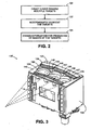
- FIG. 2 is a schematic diagram an exemplary embodiment of a method involving multi-sample inspection such as that which may be performed by the system of FIG. 1 .
- the method (or functionality) may be construed as beginning at block 120, In which X-rays are simultaneously directed toward multiple samples from an X-ray source.
- the samples are independently reoriented with respect to the X-ray source.
- each of the samples is independently supported by a corresponding movable support. As such, the samples can be moved separately in some embodiments, whereas, in others, the samples can be reoriented in synchronization with each other.
- information corresponding to attenuation of the X-rays attributable to the multiple samples is obtained for producing computed tomography images of the samples.
- obtaining of the information can be performed simultaneously with the reorienting of the samples.
- the X-rays can be collimated prior to reaching the samples. Notably, this can be in addition to collimation that occurs Internal to a housing that Is used to encase an X-ray emitter. Additionally or alternatively, the X-rays can be collimated downstream of the samples and prior to reaching an array of detectors.
- Computed tomography images of the samples can be used to perform non-destructive inspection in order to determine one or more of various characteristics.
- the characteristics can include, but are not limited to, interior shape and density of each of the samples.
- the samples can be formed of metal. Additionally or alternatively, the samples can be gas turbine engine components, such as turbine blades.
- FIG. 3 is a schematic diagram depicting another exemplary embodiment of a system involving multi-sample inspection.
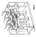
- FIG. 3 schematically depicts another embodiment of a multi-sample positioning unit.
- unit 130 includes a housing 132 that supports three samples supports (134, 144 and 154).
- a working surface 140 of the housing supports three pre-sample collimators (135, 145 and 155), three post-sample collimators (136, 146 and 156) and three detector arrays (137, 147 and 157).
- Each of the sets of inspection components is oriented within a corresponding arc of an X-ray source.
- the X-ray source emits a 30 degree fan-shaped beam of X-rays and a multi-sample positioning unit includes three sets of inspection components
- each of the sets of inspection components can be placed along a corresponding 10 degree arc (i.e., within 10 degrees of azimuth ( ⁇ ) from the X-ray source).
- ⁇ degrees of azimuth
- Working surface 140 also includes cutouts (138, 148, and 158) that are configured to receive corresponding sample supports so that the sample supports can be raised and lowered through the cutouts. This permits different horizontal planes of each of the samples to be exposed to the fan-shaped beam as the sample supports are reoriented relative to the sets of inspection components.
- each of the jacks includes a threaded shaft and a ball nut, which rides along the threaded shaft as the shaft rotates.
- four jacks (162, 163, 164 and 165) include corresponding ball nuts (166, 167, 168 and 169) that are mounted to the underside of carrier 160.
- a drive motor 170 is mechanically coupled to the jacks for rotating the shafts in unison.
- the carrier and the sample supports can be raised or lowered depending upon a direction of rotation of drive motor 170.
- drive belts are used to mechanically couple the jacks to the drive motor.
- Guide rails 172, 174 are used to prevent misalignment of the carrier during transit.
- the guide rails engage corresponding guides 173, 175 that extend from the carrier.
- an encoder 176 is used to provide information regarding a current vertical position of the carrier and, thus, of samples supported by the sample supports.
- a drive motor 180 is used to rotate the sample supports (134, 144 and 154) upon which representative samples 139, 149 and 159 are positioned.
- Drive motor 180 is configured as a worm gear in this embodiment that directly drives sample support 144.
- Following mechanisms (e.g., belts) 182, 184 engage sample support 144 and are used to drive sample supports 134 and 154 respectively.
- each of the belts 182, 184 is tensioned by a corresponding tensioner.
- belt 184 is tensioned by tensioner 185.
- An encoder 186 is used to provide information corresponding to rotational positions of the sample supports.
- a drive motor 190 is used to translate the sample supports laterally.
- drive motor 190 drives sample support 144 along rails 193 using a ball screw 191 and a jack nut 192.
- Sample supports 134 and 154 are mechanically linked to sample support 144 so that drive motor 190 translates the sample supports in unison.
- sample support 134 rides along rails 194 and sample support 154 rides along rails 195.
- rails 194 and 195 are angularly displaced with respect to rail 193, with displacement of each in this embodiment being approximately 10 degrees.
- drive motor 190 is used to alter the lateral position of the samples within the fan-shaped beam of X-rays. After rotating the sample and acquiring the desired information, the sample supports are translated in order to align different portions of the samples with the X-ray detectors. The samples are rotated again and more information is acquired. This process may repeat as necessary to ensure adequate acquisition of information.
- a computing device can be used to implement various functionality, such as that attributable to the image processor 112 and/or display/analysis system 114 depicted in FIG. 1 .
- a computing device can include a processor, memory, and one or more input and/or output (I/O) device interface(s) that are communicatively coupled via a local interface.
- the local interface can include, for example but not limited to, one or more buses and/or other wired or wireless connections.
- the local interface may have additional elements, which are omitted for simplicity, such as controllers, buffers (caches), drivers, repeaters, and receivers to enable communications. Further, the local interface may include address, control, and/or data connections to enable appropriate communications among the aforementioned components.
- the processor may be a hardware device for executing software, particularly software stored in memory.
- the processor can be a custom made or commercially available processor, a central processing unit (CPU), an auxiliary processor among several processors associated with the computing device, a semiconductor based microprocessor (in the form of a microchip or chip set) or generally any device for executing software instructions.
- the memory can include any one or combination of volatile memory elements (e.g., random access memory (RAM, such as DRAM, SRAM, SDRAM, VRAM, etc.)) and/or nonvolatile memory elements (e.g., ROM, hard drive, tape, CD-ROM, etc.).
- volatile memory elements e.g., random access memory (RAM, such as DRAM, SRAM, SDRAM, VRAM, etc.)
- nonvolatile memory elements e.g., ROM, hard drive, tape, CD-ROM, etc.
- the memory may incorporate electronic, magnetic, optical, and/or other types of storage media.
- the memory can also have a distributed architecture, where various components are situated remotely from one another, but can be accessed by the processor.
- the software in the memory may include one or more separate programs, each of which includes an ordered listing of executable instructions for implementing logical functions.
- a system component embodied as software may also be construed as a source program, executable program (object code), script, or any other entity comprising a set of instructions to be performed.
- the program is translated via a compiler, assembler, interpreter, or the like, which may or may not be included within the memory.
- the Input/Output devices that may be coupled to system I/O Interface(s) may include input devices, for example but not limited to, a keyboard, mouse, scanner, microphone, camera, proximity device, etc. Further, the Input/Output devices may also include output devices, for example but not limited to, a printer, display, etc. Finally, the Input/Output devices may further include devices that communicate both as inputs and outputs, for instance but not limited to, a modulator/demodulator (modem; for accessing another device, system, or network), a radio frequency (RF) or other transceiver, a telephonic interface, a bridge, a router, etc.
- modem for accessing another device, system, or network
- RF radio frequency
- the processor can be configured to execute software stored within the memory, to communicate data to and from the memory, and to generally control operations of the computing device pursuant to the software.
- Software in memory, in whole or in part, is read by the processor, perhaps buffered within the processor, and then executed.
Landscapes
- Health & Medical Sciences (AREA)
- Engineering & Computer Science (AREA)
- Nuclear Medicine, Radiotherapy & Molecular Imaging (AREA)
- Pulmonology (AREA)
- Radiology & Medical Imaging (AREA)
- Theoretical Computer Science (AREA)
- Physics & Mathematics (AREA)
- Life Sciences & Earth Sciences (AREA)
- Chemical & Material Sciences (AREA)
- Analytical Chemistry (AREA)
- Biochemistry (AREA)
- General Health & Medical Sciences (AREA)
- General Physics & Mathematics (AREA)
- Immunology (AREA)
- Pathology (AREA)
- Analysing Materials By The Use Of Radiation (AREA)
- Apparatus For Radiation Diagnosis (AREA)
Claims (14)
- Computertomographie-System (100) für die Untersuchung von mehreren Proben, aufweisend:eine Röntgenstrahlquelle (102);eine Probenpositioniereinheit (130) für mehrere Proben, die mehrere Probenträger (134, 144, 154) aufweist, wobei jeder der Probenträger entlang einer entsprechenden Sichtlinie der Röntgenstrahlquelle (102) des Systems angeordnet sind, wobei die Probenträger betriebsmäßig dazu ausgebildet sind, mehrere Proben (139, 149, 159) gleichzeitig derart auszurichten, dass jede der mehreren Proben in mehreren Orientierungen positionierbar ist;wobei die Probenpositioniereinheit (130) für mehrere Proben eine Trägereinrichtung (160) aufweist, die betriebsmäßig dazu ausgebildet ist, die Probenträger zu tragen, sowie einen Antriebsmotor (190) und Schienensätze (193, 194, 195) aufweist, und wobei der Antriebsmotor derart betreibbar ist, dass er die mehreren Probenträger gemeinsam in seitlicher Richtung relativ zu der Trägereinrichtung entlang der jeweiligen Schienensätze translationsmäßig bewegt;dadurch gekennzeichnet, dass die Trägereinrichtung zum Etablieren von vertikalen Positionen der Probenträger relativ zu der Röntgenstrahlquelle (102) bewegbar ist, und dass die Schienensätze in Bezug auf benachbarte Schienensätze jeweils winkelmäßig versetzt sind.
- System nach Anspruch 1,
wobei jede der mehreren Probenträger (134, 144, 154) drehbar ist, um eine Probe zu drehen. - System nach Anspruch 2,
wobei die Probenträger (134, 144, 154) betriebsmäßig dazu ausgebildet sind, sich synchron miteinander zu drehen. - System nach Anspruch 2 oder 3,
wobei die Probenpositioniereinheit (130) für mehrere Proben einen Antriebsmotor (180) und einen Folgemechanismus (182, 184) aufweist, wobei der Antriebsmotor betriebsmäßig dazu ausgebildet ist, einen ersten (144) der Probenträger antriebsmäßig zu bewegen, und wobei der Folgemechanismus durch den ersten der Probenträger antriebsmäßg bewegt wird und betriebsmäßig dazu ausgebildet ist, einen zweiten (134, 154) der Probenträger antriebsmäßig zu bewegen. - System nach Anspruch 4,
wobei der Folgemechanismus (182, 184) ein Riemen ist. - System nach einem der vorhergehenden Ansprüche,
wobei die Probenträger (134, 144, 154) ferner betriebsmäßig dazu ausgebildet sind, vertikale Positionen der Proben zu verändern. - System nach Anspruch 6,
wobei die Probenträger (134, 144, 154) betriebsmäßig dazu ausgebildet sind, vertikale Positionen der Proben synchron miteinander zu verändern. - System nach Anspruch 1,
wobei die Probenpositioniereinheit für mehrere Proben eine oder mehrere Hebeeinrichtungen (162-165) aufweist, die zum Anheben und Absenken der Trägereinrichtung (160) ausgebildet sind, wobei die oder jede Hebeeinrichtung eine Gewindestange und einer Kugelumlaufmutter (166-169) aufweist, wobei die Kugelumlaufmutter mit der Trägereinrichtung gekoppelt ist und betriebsmäßig dazu ausgebildet ist, sich in einer der Rotationsrichtung der Stange entsprechenden Richtung die Stange entlang zu bewegen. - System nach Anspruch 8, wobei:die Probenpositioniereinheit für mehrere Proben einen Antriebsmotor (170) aufweist; undwobei die Hebeeinrichtung(en) durch den Antriebsmotor antriebsmäßig bewegt wird(werden).
- System nach einem der vorhergehenden Ansprüche, wobei:die Probenpositioniereinheit für mehrere Proben eine Arbeitsfläche aufweist; undwobei das System ferner eine Anordnung von Röntgenstrahldetektoren (110) aufweist, die von der Arbeitsfläche getragen sind.
- System nach Anspruch 10,
das ferner einen Röntgenstrahl-Kollimator (108) aufweist, der von der Arbeitsfläche getragen ist; wobei vorzugsweise der Kollimator ein nachgeordneter Proben-Kollimator ist, der stromabwärts von den Probenträgern angeordnet ist. - Verfahren zum Durchführen einer Computertomographie an mehrere Proben, das folgende Schritte aufweist:Vorsehen einer Probenpositioniereinheit (130) für mehrere Proben, die eine Trägereinrichtung (160) aufweist, die eine Mehrzahl von Probenträgern (134, 144) trägt, wobei die Probenträger betriebsmäßig dazu ausgebildet sind, mehrere Proben (139, 149, 159) gleichzeitig derart auszurichten, dass jede der mehreren Proben in mehreren Orientierungen positionierbar ist, wobei die Trägereinrichtung (160) zum Etablieren von vertikalen Positionen der Probenträger relativ zu einer Röntgenstrahlquelle (102) bewegbar ist und einen Antriebsmotor (109) sowie Schienensätze (193, 194, 195) aufweist, wobei die Schienensätze in Bezug auf benachbarte Schienensätze jeweils winkelmäßig versetzt sind;gleichzeitiges Richten von Röntgenstrahlen von der Röntgenstrahlquelle (102) auf mehrere Proben;während des Richtens der Röntgenstrahlen erfolgende Neuausrichtung der Proben in Bezug auf die Röntgenstrahlquelle unter Verwendung des Antriebsmotors zum translationsmäßigen Bewegen der Mehrzahl von Probenträgern gemeinsam in seitlicher Richtung relativ zu der Trägereinrichtung entlang der jeweiligen Schienensätze; undErhalten (124) von Information entsprechend der auf die mehreren Proben zurückzuführenden Dämpfung der Röntgenstrahlen, um Computertomographie-Bilder der Proben zu erzeugen.
- Verfahren nach Anspruch 12,
wobei bei der Neuausrichtung der Proben die Proben synchron miteinander neu ausgerichtet werden. - Verfahren nach Anspruch 12 oder 13,
wobei bei der Neuausrichtung der Proben jede der Proben in unabhängiger Weise von einem entsprechenden Probenträger (134, 144, 154) getragen wird.
Applications Claiming Priority (1)
| Application Number | Priority Date | Filing Date | Title |
|---|---|---|---|
| US12/099,899 US7876875B2 (en) | 2008-04-09 | 2008-04-09 | Computed tomography systems and related methods involving multi-target inspection |
Publications (2)
| Publication Number | Publication Date |
|---|---|
| EP2108945A1 EP2108945A1 (de) | 2009-10-14 |
| EP2108945B1 true EP2108945B1 (de) | 2014-10-15 |
Family
ID=40666803
Family Applications (1)
| Application Number | Title | Priority Date | Filing Date |
|---|---|---|---|
| EP09250908.2A Expired - Fee Related EP2108945B1 (de) | 2008-04-09 | 2009-03-27 | Vorrichtung und Verfahren zur Computer-Tomographie, welche einen Probenhalter zur Aufnahme von mehreren Proben enthalten |
Country Status (2)
| Country | Link |
|---|---|
| US (1) | US7876875B2 (de) |
| EP (1) | EP2108945B1 (de) |
Cited By (1)
| Publication number | Priority date | Publication date | Assignee | Title |
|---|---|---|---|---|
| EP4592506A1 (de) * | 2024-01-25 | 2025-07-30 | Chromalloy Gas Turbine LLC | Turbinenkomponentenhalter zur bildgebung |
Families Citing this family (16)
| Publication number | Priority date | Publication date | Assignee | Title |
|---|---|---|---|---|
| WO2013051594A1 (ja) * | 2011-10-04 | 2013-04-11 | 株式会社ニコン | X線装置、x線照射方法、及び構造物の製造方法 |
| US8750561B2 (en) | 2012-02-29 | 2014-06-10 | United Technologies Corporation | Method of detecting material in a part |
| US10247682B2 (en) * | 2013-04-04 | 2019-04-02 | Illinois Tool Works Inc. | Helical computed tomography |
| JP6147852B2 (ja) * | 2013-05-10 | 2017-06-14 | 株式会社ニコン | X線装置及び構造物の製造方法 |
| GB201508064D0 (en) * | 2015-05-12 | 2015-06-24 | Rolls Royce Plc | A method of scanning aerofoil blades |
| GB201508065D0 (en) * | 2015-05-12 | 2015-06-24 | Rolls Royce Plc | A method of scanning Aerofoil blades |
| US20170023495A1 (en) * | 2015-07-20 | 2017-01-26 | Apple Inc. | Universal computerized tomography fixture system with a multi-scan robotic positioning apparatus |
| DE102015222480A1 (de) * | 2015-11-13 | 2017-05-18 | Fraunhofer-Gesellschaft zur Förderung der angewandten Forschung e.V. | Röntgensystem, Rotationseinheit und Verfahren |
| EP3532830B1 (de) * | 2016-10-31 | 2021-12-15 | Fraunhofer-Gesellschaft zur Förderung der angewandten Forschung e.V. | Anpassung für einen drehtisch eines ct-systems |
| JP6708857B2 (ja) * | 2017-10-17 | 2020-06-10 | 日本装置開発株式会社 | X線検査装置 |
| GB201901244D0 (en) | 2019-01-30 | 2019-03-20 | Rolls Royce Plc | Method of determining the displacement of a component, computer program comprising code to preform the method |
| US11448605B2 (en) * | 2019-02-14 | 2022-09-20 | Psylotech, Inc. | Scanner load frame |
| US20250334526A1 (en) * | 2022-09-28 | 2025-10-30 | Deltaray Bv | Radiation imaging system for inspection of items and method therefor |
| US12607578B2 (en) * | 2023-06-15 | 2026-04-21 | Illinois Tool Works Inc. | Accelerated higher resolution industrial radiography |
| DE102023206858A1 (de) * | 2023-07-19 | 2025-01-23 | Fraunhofer-Gesellschaft zur Förderung der angewandten Forschung eingetragener Verein | Röntgensystem und CT-System |
| SE2351080A1 (en) * | 2023-09-18 | 2025-03-19 | Northvolt Ab | A battery cell imaging apparatus |
Family Cites Families (80)
| Publication number | Priority date | Publication date | Assignee | Title |
|---|---|---|---|---|
| US2741710A (en) * | 1949-10-05 | 1956-04-10 | Bartow Beacons Inc | Directivity control of x-rays |
| US4054800A (en) * | 1975-07-28 | 1977-10-18 | Engineering Dynamics Corporation | Methods of collimator fabrication |
| US4211927A (en) * | 1978-11-24 | 1980-07-08 | Cgr Medical Corporation | Computerized tomography system |
| US4242587A (en) * | 1979-06-07 | 1980-12-30 | Charles Lescrenier | Patient positioning device comprising light planes corresponding to first, second and third intersecting reference planes |
| DE3123685A1 (de) * | 1980-06-19 | 1982-03-18 | Fuji Electric Co., Ltd., Kawasaki, Kanagawa | Verfahren zur wanddicken-messung von rohrfoermigen gegenstaenden |
| JPS57103629A (en) * | 1980-12-17 | 1982-06-28 | Tokyo Shibaura Electric Co | Positioning apparatus of radioactive ray tomograph apparatus |
| US4453226A (en) * | 1981-07-15 | 1984-06-05 | United Technologies Corporation | Method and apparatus for particle size determination in a host material |
| US4521372A (en) * | 1981-08-26 | 1985-06-04 | Nuclear Monitoring Systems & Management Corporation | Apparatus and method for monitoring stored material |
| US4636475A (en) * | 1981-08-26 | 1987-01-13 | Price William E | Apparatus and method for monitoring stored material |
| US4599740A (en) * | 1983-01-06 | 1986-07-08 | Cable Arthur P | Radiographic examination system |
| US4691332A (en) * | 1983-03-14 | 1987-09-01 | American Science And Engineering, Inc. | High energy computed tomography |
| JPS60256034A (ja) | 1984-06-01 | 1985-12-17 | Toshiba Corp | 産業用ctスキヤナ |
| US4821511A (en) * | 1986-10-31 | 1989-04-18 | United Technologies Corporation | Liner for a solid propellant rocket motor |
| US4872191A (en) * | 1987-11-19 | 1989-10-03 | Bio-Imaging Research, Inc. | Cam-controlled automatic dynamic focusing for computed tomography |
| US4825454A (en) * | 1987-12-28 | 1989-04-25 | American Science And Engineering, Inc. | Tomographic imaging with concentric conical collimator |
| US4969110A (en) * | 1988-08-01 | 1990-11-06 | General Electric Company | Method of using a priori information in computerized tomography |
| US4989225A (en) * | 1988-08-18 | 1991-01-29 | Bio-Imaging Research, Inc. | Cat scanner with simultaneous translation and rotation of objects |
| JPH07119837B2 (ja) * | 1990-05-30 | 1995-12-20 | 株式会社日立製作所 | Ct装置及び透過装置並びにx線発生装置 |
| US5119408A (en) * | 1990-10-31 | 1992-06-02 | General Electric Company | Rotate/rotate method and apparatus for computed tomography x-ray inspection of large objects |
| US5131021A (en) * | 1991-06-21 | 1992-07-14 | General Electric Company | Computed tomography system with control and correction of fan beam position |
| US5140661A (en) * | 1991-08-06 | 1992-08-18 | G & H Technology, Inc. | Optical fiber terminus |
| JP2654733B2 (ja) | 1992-05-12 | 1997-09-17 | 動力炉・核燃料開発事業団 | X線ct装置用コリメータ |
| JPH06103959A (ja) * | 1992-09-21 | 1994-04-15 | Hamamatsu Photonics Kk | 光電子増倍管の集合装置 |
| JPH06237927A (ja) | 1993-02-15 | 1994-08-30 | Hitachi Medical Corp | 放射線画像撮影装置 |
| US5550378A (en) * | 1993-04-05 | 1996-08-27 | Cardiac Mariners, Incorporated | X-ray detector |
| US5430298A (en) * | 1994-06-21 | 1995-07-04 | General Electric Company | CT array with improved photosensor linearity and reduced crosstalk |
| JP3309618B2 (ja) | 1995-01-11 | 2002-07-29 | 株式会社日立製作所 | X線ct装置 |
| US5555283A (en) * | 1995-06-07 | 1996-09-10 | Board Of Regents Of The University Of Texas System | Computer-controlled miniature multileaf collimator |
| DE19639861A1 (de) * | 1995-09-28 | 1997-04-10 | Brainlab Med Computersyst Gmbh | Lamellenkollimator für die Strahlentherapie |
| DE19536804A1 (de) * | 1995-10-02 | 1997-04-03 | Deutsches Krebsforsch | Konturenkollimator für die Strahlentherapie |
| US5652429A (en) * | 1995-10-19 | 1997-07-29 | Digital Scintigraphics, Inc. | Liquid interface scintillation camera |
| WO1998002763A1 (en) * | 1996-07-12 | 1998-01-22 | American Science And Engineering, Inc. | Side scatter tomography system |
| US5799057A (en) * | 1996-12-26 | 1998-08-25 | General Electric Company | Collimator and detector for computed tomography systems |
| US6041132A (en) * | 1997-07-29 | 2000-03-21 | General Electric Company | Computed tomography inspection of composite ply structure |
| JPH1151879A (ja) * | 1997-07-31 | 1999-02-26 | Shimadzu Corp | 非破壊検査装置 |
| US6167110A (en) * | 1997-11-03 | 2000-12-26 | General Electric Company | High voltage x-ray and conventional radiography imaging apparatus and method |
| US5991357A (en) * | 1997-12-16 | 1999-11-23 | Analogic Corporation | Integrated radiation detecting and collimating assembly for X-ray tomography system |
| US5982846A (en) * | 1998-04-13 | 1999-11-09 | General Electric Company | Methods and apparatus for dose reduction in a computed tomograph |
| US6421420B1 (en) * | 1998-12-01 | 2002-07-16 | American Science & Engineering, Inc. | Method and apparatus for generating sequential beams of penetrating radiation |
| US6229872B1 (en) * | 1998-12-22 | 2001-05-08 | United Technologies Corporation | Method and apparatus for use in inspection of objects |
| DE19927953A1 (de) * | 1999-06-18 | 2001-01-11 | Siemens Ag | Röntgendiagnostikgerät |
| JP3426540B2 (ja) * | 1999-07-12 | 2003-07-14 | 理学電機工業株式会社 | 試料交換機を有する分析システム |
| US6552348B2 (en) * | 1999-12-14 | 2003-04-22 | Regents Of The University Of California | Apparatus and method for breast cancer imaging |
| US6438210B1 (en) * | 2000-03-28 | 2002-08-20 | General Electric Company | Anti-scatter grid, method, and apparatus for forming same |
| FR2808091B1 (fr) * | 2000-04-25 | 2002-07-05 | Dimason | Dispositif perfectionne de collection de rayonnements ionisants et ensemble de collection equipe d'un tel dispositif |
| DE10047720A1 (de) * | 2000-09-27 | 2002-04-11 | Philips Corp Intellectual Pty | Vorrichtung und Verfahren zur Erzeugung eines Röntgen-Computertomogramms mit einer Streustrahlungskorrektur |
| DE10055739B4 (de) * | 2000-11-10 | 2006-04-27 | Siemens Ag | Streustrahlungskorrekturverfahren für eine Röntgen-Computertomographieeinrichtung |
| US6671541B2 (en) * | 2000-12-01 | 2003-12-30 | Neomed Technologies, Inc. | Cardiovascular imaging and functional analysis system |
| US7204019B2 (en) * | 2001-08-23 | 2007-04-17 | United Technologies Corporation | Method for repairing an apertured gas turbine component |
| US6879715B2 (en) * | 2001-12-05 | 2005-04-12 | General Electric Company | Iterative X-ray scatter correction method and apparatus |
| CN100398066C (zh) * | 2002-03-13 | 2008-07-02 | 分离成像有限责任公司 | 准同步多平面x射线成像的系统和方法 |
| US6868138B2 (en) * | 2002-05-29 | 2005-03-15 | The Regents Of The University Of Michigan | Method, processor and computed tomography (CT) machine for generating images utilizing high and low sensitivity data collected from a flat panel detector having an extended dynamic range |
| US7356115B2 (en) * | 2002-12-04 | 2008-04-08 | Varian Medical Systems Technology, Inc. | Radiation scanning units including a movable platform |
| US6979826B2 (en) * | 2002-07-29 | 2005-12-27 | Ge Medical Systems Global Technology Company Llc | Scintillator geometry for enhanced radiation detection and reduced error sensitivity |
| US7187800B2 (en) * | 2002-08-02 | 2007-03-06 | Computerized Medical Systems, Inc. | Method and apparatus for image segmentation using Jensen-Shannon divergence and Jensen-Renyi divergence |
| US7115876B2 (en) * | 2002-12-02 | 2006-10-03 | General Electric Company | Imaging array and methods for fabricating same |
| US7120282B2 (en) * | 2003-01-29 | 2006-10-10 | General Electric Company | Method and apparatus for correcting digital X-ray images |
| US6934642B2 (en) * | 2003-04-16 | 2005-08-23 | Mississippi State University | Method for determining superficial residual stress as applied to machined, mechanically or thermally processed surfaces |
| DE10322531B4 (de) * | 2003-05-19 | 2010-09-16 | Siemens Ag | Streustrahlenraster oder Kollimator |
| US7095028B2 (en) * | 2003-10-15 | 2006-08-22 | Varian Medical Systems | Multi-slice flat panel computed tomography |
| US7185662B2 (en) * | 2003-11-14 | 2007-03-06 | United Technologies Corporation | Methods of preparing, cleaning and repairing article and article repaired |
| US7099435B2 (en) * | 2003-11-15 | 2006-08-29 | Agilent Technologies, Inc | Highly constrained tomography for automated inspection of area arrays |
| US7254209B2 (en) * | 2003-11-17 | 2007-08-07 | General Electric Company | Iterative CT reconstruction method using multi-modal edge information |
| US7133491B2 (en) * | 2004-01-15 | 2006-11-07 | Bio-Imaging Research, Inc. | Traveling X-ray inspection system with collimators |
| US7216694B2 (en) * | 2004-01-23 | 2007-05-15 | United Technologies Corporation | Apparatus and method for reducing operating stress in a turbine blade and the like |
| DE102005018447A1 (de) * | 2005-04-20 | 2006-10-26 | Werth Messtechnik Gmbh | Verfahren zum Messen eines Objektes |
| US8804905B2 (en) * | 2004-05-26 | 2014-08-12 | Werth Messtechnik Gmbh | Coordinate measuring apparatus and method for measuring an object |
| US7283608B2 (en) * | 2004-08-24 | 2007-10-16 | General Electric Company | System and method for X-ray imaging using X-ray intensity information |
| US7254211B2 (en) * | 2004-09-14 | 2007-08-07 | Hitachi, Ltd. | Method and apparatus for performing computed tomography |
| DE102004047616B4 (de) * | 2004-09-30 | 2008-02-28 | Siemens Ag | Verfahren zur Herstellung eines Kollimators, insbesondere für einen Computertomogaphen, sowie eine Gussform zur Durchführung des Verfahrens |
| US20060067471A1 (en) * | 2004-09-30 | 2006-03-30 | General Electric Company | Linear array detector system and inspection method |
| US7200201B2 (en) * | 2004-11-16 | 2007-04-03 | General Electric Company | Flat panel detector based slot scanning configuration |
| JP4488885B2 (ja) | 2004-12-17 | 2010-06-23 | 株式会社日立製作所 | Ct装置 |
| DE102005044650B4 (de) * | 2005-09-19 | 2008-07-10 | Siemens Ag | Streustahlenraster mit einer zellenartigen Struktur von Strahlungskanälen und Verfahren zur Herstellung eines solchen Streustrahlenrasters |
| US7286630B2 (en) * | 2005-12-16 | 2007-10-23 | Varian Medical Systems Technologies, Inc. | Method and apparatus for facilitating enhanced CT scanning |
| US7283605B2 (en) * | 2006-01-14 | 2007-10-16 | General Electric Company | Methods and apparatus for scatter correction |
| US7341376B2 (en) * | 2006-03-23 | 2008-03-11 | General Electric Company | Method for aligning radiographic inspection system |
| US7272207B1 (en) * | 2006-03-24 | 2007-09-18 | Richard Aufrichtig | Processes and apparatus for variable binning of data in non-destructive imaging |
| US7492862B2 (en) * | 2007-01-17 | 2009-02-17 | Ge Homeland Protection, Inc. | Computed tomography cargo inspection system and method |
| US20080298546A1 (en) * | 2007-05-31 | 2008-12-04 | General Electric Company | Cargo container inspection method |
-
2008
- 2008-04-09 US US12/099,899 patent/US7876875B2/en active Active
-
2009
- 2009-03-27 EP EP09250908.2A patent/EP2108945B1/de not_active Expired - Fee Related
Cited By (2)
| Publication number | Priority date | Publication date | Assignee | Title |
|---|---|---|---|---|
| EP4592506A1 (de) * | 2024-01-25 | 2025-07-30 | Chromalloy Gas Turbine LLC | Turbinenkomponentenhalter zur bildgebung |
| US12612867B2 (en) | 2024-01-25 | 2026-04-28 | Chromalloy Gas Turbine Llc | Turbine component holder for imaging |
Also Published As
| Publication number | Publication date |
|---|---|
| US20090257552A1 (en) | 2009-10-15 |
| EP2108945A1 (de) | 2009-10-14 |
| US7876875B2 (en) | 2011-01-25 |
Similar Documents
| Publication | Publication Date | Title |
|---|---|---|
| EP2108945B1 (de) | Vorrichtung und Verfahren zur Computer-Tomographie, welche einen Probenhalter zur Aufnahme von mehreren Proben enthalten | |
| US7775715B2 (en) | Method of calibration for computed tomography scanners utilized in quality control applications | |
| JP5009563B2 (ja) | 試料の検査方法および装置 | |
| US7242749B2 (en) | Methods and systems for dynamic pitch helical scanning | |
| US12019036B2 (en) | Transmissive small-angle scattering device | |
| US20090213984A1 (en) | Computed Tomography Systems and Related Methods Involving Post-Target Collimation | |
| US20090213994A1 (en) | Computed Tomography Systems and Related Methods Involving Forward Collimation | |
| CN101140246A (zh) | X射线ct检查设备以及用于检查对象的ct方法 | |
| US9606072B2 (en) | Radiation inspecting apparatus | |
| JP2007041002A (ja) | X線ct検査装置及びct検査方法 | |
| JPH05126767A (ja) | 放射分析装置 | |
| CN118032822A (zh) | 产生透视图像来重构平面对象中的体积的方法 | |
| JP5031215B2 (ja) | 多機能x線分析システム | |
| EP2099035A1 (de) | Röntgen-Kollimatoren und dazugehörige Systeme und Verfahren mit derartigen Kollimatoren | |
| JP5569061B2 (ja) | X線検査方法、x線検査装置およびx線検査プログラム | |
| US4177382A (en) | Radiography | |
| JP2013104762A (ja) | X線分析装置および方法 | |
| JP4619282B2 (ja) | エックス線分析装置 | |
| JP4894359B2 (ja) | X線断層撮像装置及びx線断層撮像方法 | |
| WO2012029358A1 (ja) | X線分析装置および方法 | |
| JP2013104717A (ja) | 回折x線検出方法およびx線回折装置 | |
| JP2000037377A (ja) | 検出器及びマルチスライス型コンピュ―タ断層撮影システム | |
| CN220271206U (zh) | 一种x射线样品分析装置 | |
| JP2007333509A (ja) | 放射線を用いた断層撮影装置及び断層撮影方法 | |
| JP7265159B2 (ja) | 分析装置および分析方法 |
Legal Events
| Date | Code | Title | Description |
|---|---|---|---|
| PUAI | Public reference made under article 153(3) epc to a published international application that has entered the european phase |
Free format text: ORIGINAL CODE: 0009012 |
|
| AK | Designated contracting states |
Kind code of ref document: A1 Designated state(s): AT BE BG CH CY CZ DE DK EE ES FI FR GB GR HR HU IE IS IT LI LT LU LV MC MK MT NL NO PL PT RO SE SI SK TR |
|
| AX | Request for extension of the european patent |
Extension state: AL BA RS |
|
| 17P | Request for examination filed |
Effective date: 20091222 |
|
| 17Q | First examination report despatched |
Effective date: 20100126 |
|
| AKX | Designation fees paid |
Designated state(s): DE GB |
|
| GRAP | Despatch of communication of intention to grant a patent |
Free format text: ORIGINAL CODE: EPIDOSNIGR1 |
|
| INTG | Intention to grant announced |
Effective date: 20131107 |
|
| GRAP | Despatch of communication of intention to grant a patent |
Free format text: ORIGINAL CODE: EPIDOSNIGR1 |
|
| INTG | Intention to grant announced |
Effective date: 20140502 |
|
| GRAS | Grant fee paid |
Free format text: ORIGINAL CODE: EPIDOSNIGR3 |
|
| GRAA | (expected) grant |
Free format text: ORIGINAL CODE: 0009210 |
|
| AK | Designated contracting states |
Kind code of ref document: B1 Designated state(s): DE GB |
|
| REG | Reference to a national code |
Ref country code: GB Ref legal event code: FG4D |
|
| REG | Reference to a national code |
Ref country code: DE Ref legal event code: R096 Ref document number: 602009027174 Country of ref document: DE Effective date: 20141127 |
|
| PGFP | Annual fee paid to national office [announced via postgrant information from national office to epo] |
Ref country code: DE Payment date: 20150324 Year of fee payment: 7 |
|
| PGFP | Annual fee paid to national office [announced via postgrant information from national office to epo] |
Ref country code: GB Payment date: 20150325 Year of fee payment: 7 |
|
| REG | Reference to a national code |
Ref country code: DE Ref legal event code: R097 Ref document number: 602009027174 Country of ref document: DE |
|
| PLBE | No opposition filed within time limit |
Free format text: ORIGINAL CODE: 0009261 |
|
| STAA | Information on the status of an ep patent application or granted ep patent |
Free format text: STATUS: NO OPPOSITION FILED WITHIN TIME LIMIT |
|
| 26N | No opposition filed |
Effective date: 20150716 |
|
| REG | Reference to a national code |
Ref country code: DE Ref legal event code: R119 Ref document number: 602009027174 Country of ref document: DE |
|
| GBPC | Gb: european patent ceased through non-payment of renewal fee |
Effective date: 20160327 |
|
| PG25 | Lapsed in a contracting state [announced via postgrant information from national office to epo] |
Ref country code: GB Free format text: LAPSE BECAUSE OF NON-PAYMENT OF DUE FEES Effective date: 20160327 Ref country code: DE Free format text: LAPSE BECAUSE OF NON-PAYMENT OF DUE FEES Effective date: 20161001 |