EP2108926B1 - Kodierrad-Herstellungsverfahren, Kodierrad, Drehcodierer, Drehsteuereinheit, Riementrägereinheit und Bildgebungsvorrichtung - Google Patents
Kodierrad-Herstellungsverfahren, Kodierrad, Drehcodierer, Drehsteuereinheit, Riementrägereinheit und Bildgebungsvorrichtung Download PDFInfo
- Publication number
- EP2108926B1 EP2108926B1 EP09250813.4A EP09250813A EP2108926B1 EP 2108926 B1 EP2108926 B1 EP 2108926B1 EP 09250813 A EP09250813 A EP 09250813A EP 2108926 B1 EP2108926 B1 EP 2108926B1
- Authority
- EP
- European Patent Office
- Prior art keywords
- hole
- code
- code wheel
- mark
- manufacturing
- Prior art date
- Legal status (The legal status is an assumption and is not a legal conclusion. Google has not performed a legal analysis and makes no representation as to the accuracy of the status listed.)
- Not-in-force
Links
- 238000004519 manufacturing process Methods 0.000 title claims description 46
- 238000000034 method Methods 0.000 claims description 49
- 239000003086 colorant Substances 0.000 claims description 12
- 238000006073 displacement reaction Methods 0.000 description 72
- 238000012546 transfer Methods 0.000 description 48
- 230000015572 biosynthetic process Effects 0.000 description 15
- 238000004140 cleaning Methods 0.000 description 11
- 238000005530 etching Methods 0.000 description 9
- 239000011521 glass Substances 0.000 description 9
- 238000000206 photolithography Methods 0.000 description 9
- 238000005259 measurement Methods 0.000 description 7
- 230000003287 optical effect Effects 0.000 description 7
- 230000002950 deficient Effects 0.000 description 5
- 238000007689 inspection Methods 0.000 description 5
- 229920002120 photoresistant polymer Polymers 0.000 description 5
- 239000000463 material Substances 0.000 description 4
- 108091008695 photoreceptors Proteins 0.000 description 4
- 238000013019 agitation Methods 0.000 description 3
- 239000004677 Nylon Substances 0.000 description 2
- 229930182556 Polyacetal Natural products 0.000 description 2
- 238000009826 distribution Methods 0.000 description 2
- 230000000694 effects Effects 0.000 description 2
- 238000012423 maintenance Methods 0.000 description 2
- 229920001778 nylon Polymers 0.000 description 2
- 229920000139 polyethylene terephthalate Polymers 0.000 description 2
- 239000005020 polyethylene terephthalate Substances 0.000 description 2
- 229920006324 polyoxymethylene Polymers 0.000 description 2
- 238000005096 rolling process Methods 0.000 description 2
- 239000000758 substrate Substances 0.000 description 2
- 238000012356 Product development Methods 0.000 description 1
- 238000010521 absorption reaction Methods 0.000 description 1
- 238000004458 analytical method Methods 0.000 description 1
- 238000004364 calculation method Methods 0.000 description 1
- 230000003247 decreasing effect Effects 0.000 description 1
- 238000011161 development Methods 0.000 description 1
- 230000005684 electric field Effects 0.000 description 1
- 238000005286 illumination Methods 0.000 description 1
- 239000002184 metal Substances 0.000 description 1
- 229910052751 metal Inorganic materials 0.000 description 1
- 239000007769 metal material Substances 0.000 description 1
- 238000006386 neutralization reaction Methods 0.000 description 1
- 230000035699 permeability Effects 0.000 description 1
- 239000004033 plastic Substances 0.000 description 1
- 229920003023 plastic Polymers 0.000 description 1
- -1 polyethylene terephthalate Polymers 0.000 description 1
- 238000003908 quality control method Methods 0.000 description 1
- 239000011347 resin Substances 0.000 description 1
- 229920005989 resin Polymers 0.000 description 1
- 230000000087 stabilizing effect Effects 0.000 description 1
- 229910001220 stainless steel Inorganic materials 0.000 description 1
- 239000010935 stainless steel Substances 0.000 description 1
- 238000003860 storage Methods 0.000 description 1
- 238000012360 testing method Methods 0.000 description 1
Images










Classifications
-
- G—PHYSICS
- G01—MEASURING; TESTING
- G01D—MEASURING NOT SPECIALLY ADAPTED FOR A SPECIFIC VARIABLE; ARRANGEMENTS FOR MEASURING TWO OR MORE VARIABLES NOT COVERED IN A SINGLE OTHER SUBCLASS; TARIFF METERING APPARATUS; MEASURING OR TESTING NOT OTHERWISE PROVIDED FOR
- G01D5/00—Mechanical means for transferring the output of a sensing member; Means for converting the output of a sensing member to another variable where the form or nature of the sensing member does not constrain the means for converting; Transducers not specially adapted for a specific variable
- G01D5/26—Mechanical means for transferring the output of a sensing member; Means for converting the output of a sensing member to another variable where the form or nature of the sensing member does not constrain the means for converting; Transducers not specially adapted for a specific variable characterised by optical transfer means, i.e. using infrared, visible, or ultraviolet light
- G01D5/32—Mechanical means for transferring the output of a sensing member; Means for converting the output of a sensing member to another variable where the form or nature of the sensing member does not constrain the means for converting; Transducers not specially adapted for a specific variable characterised by optical transfer means, i.e. using infrared, visible, or ultraviolet light with attenuation or whole or partial obturation of beams of light
- G01D5/34—Mechanical means for transferring the output of a sensing member; Means for converting the output of a sensing member to another variable where the form or nature of the sensing member does not constrain the means for converting; Transducers not specially adapted for a specific variable characterised by optical transfer means, i.e. using infrared, visible, or ultraviolet light with attenuation or whole or partial obturation of beams of light the beams of light being detected by photocells
- G01D5/347—Mechanical means for transferring the output of a sensing member; Means for converting the output of a sensing member to another variable where the form or nature of the sensing member does not constrain the means for converting; Transducers not specially adapted for a specific variable characterised by optical transfer means, i.e. using infrared, visible, or ultraviolet light with attenuation or whole or partial obturation of beams of light the beams of light being detected by photocells using displacement encoding scales
- G01D5/3473—Circular or rotary encoders
-
- G—PHYSICS
- G01—MEASURING; TESTING
- G01D—MEASURING NOT SPECIALLY ADAPTED FOR A SPECIFIC VARIABLE; ARRANGEMENTS FOR MEASURING TWO OR MORE VARIABLES NOT COVERED IN A SINGLE OTHER SUBCLASS; TARIFF METERING APPARATUS; MEASURING OR TESTING NOT OTHERWISE PROVIDED FOR
- G01D5/00—Mechanical means for transferring the output of a sensing member; Means for converting the output of a sensing member to another variable where the form or nature of the sensing member does not constrain the means for converting; Transducers not specially adapted for a specific variable
- G01D5/26—Mechanical means for transferring the output of a sensing member; Means for converting the output of a sensing member to another variable where the form or nature of the sensing member does not constrain the means for converting; Transducers not specially adapted for a specific variable characterised by optical transfer means, i.e. using infrared, visible, or ultraviolet light
- G01D5/32—Mechanical means for transferring the output of a sensing member; Means for converting the output of a sensing member to another variable where the form or nature of the sensing member does not constrain the means for converting; Transducers not specially adapted for a specific variable characterised by optical transfer means, i.e. using infrared, visible, or ultraviolet light with attenuation or whole or partial obturation of beams of light
- G01D5/34—Mechanical means for transferring the output of a sensing member; Means for converting the output of a sensing member to another variable where the form or nature of the sensing member does not constrain the means for converting; Transducers not specially adapted for a specific variable characterised by optical transfer means, i.e. using infrared, visible, or ultraviolet light with attenuation or whole or partial obturation of beams of light the beams of light being detected by photocells
- G01D5/347—Mechanical means for transferring the output of a sensing member; Means for converting the output of a sensing member to another variable where the form or nature of the sensing member does not constrain the means for converting; Transducers not specially adapted for a specific variable characterised by optical transfer means, i.e. using infrared, visible, or ultraviolet light with attenuation or whole or partial obturation of beams of light the beams of light being detected by photocells using displacement encoding scales
- G01D5/34707—Scales; Discs, e.g. fixation, fabrication, compensation
-
- B—PERFORMING OPERATIONS; TRANSPORTING
- B65—CONVEYING; PACKING; STORING; HANDLING THIN OR FILAMENTARY MATERIAL
- B65H—HANDLING THIN OR FILAMENTARY MATERIAL, e.g. SHEETS, WEBS, CABLES
- B65H2553/00—Sensing or detecting means
- B65H2553/51—Encoders, e.g. linear
-
- Y—GENERAL TAGGING OF NEW TECHNOLOGICAL DEVELOPMENTS; GENERAL TAGGING OF CROSS-SECTIONAL TECHNOLOGIES SPANNING OVER SEVERAL SECTIONS OF THE IPC; TECHNICAL SUBJECTS COVERED BY FORMER USPC CROSS-REFERENCE ART COLLECTIONS [XRACs] AND DIGESTS
- Y10—TECHNICAL SUBJECTS COVERED BY FORMER USPC
- Y10T—TECHNICAL SUBJECTS COVERED BY FORMER US CLASSIFICATION
- Y10T29/00—Metal working
- Y10T29/49—Method of mechanical manufacture
- Y10T29/49481—Wheel making
Definitions
- the present invention relates to a code wheel manufacturing method, a code wheel, a rotary encoder, a rotation control unit, and an image forming apparatus.
- a rotary encoder for accurately measuring the rotation speed of a rotary member is well known.
- the rotary encoder is used to control the rotation speed of a rotary member such as a carrier roller for a belt, a storage medium, an ink nozzle head, or a photoreceptor in an image forming apparatus such as an electrophotographic or inkjet type printer, a photocopier, a facsimile machine, a printing machine or the like.
- An optical rotary encoder is configured to include an encode sensor and a code wheel (encoder disc) having a ring-like code portion (modified optical track) including a uniform, radial code pattern on an outer circumference.
- the code wheel is mounted on the rotary member so that it concentrically rotates with the rotary member, and the rotary encoder can accurately detect the rotation speed of the rotary member according to signals read from the code pattern of a rotating code wheel with the encode sensor.
- a rotary encoder is adapted to various rotation speed detectors and rotation control units owing to its compact size and accurate detectability.
- Japanese Unexamined Patent Application Publication No. 2005-134763 discloses a feedback control method using a rotary encoder for the rotation speed of a rotary member as a carrier roller of a belt carrier unit of an image forming apparatus.
- FIG. 8 shows an example of a code wheel of a prior art rotary encoder.
- a code portion 201 (modulated optical track) is formed with micron-level high precision by etching or photolithography.
- One of the key factors to determine performance of the rotary encoder is precision of intervals between codes of a code pattern of the code portion 201.
- the code portion 201 can be precisely formed by etching or photolithography easily, and the precision is maintainable.
- Another factor to determine accuracy of signals from a code pattern is a degree of coincidence (axial runout) between a center position of the ring-like code portion 201 and a rotational center thereof when the code wheel is mounted on the rotary member and rotated. Unless the code portion 201 is rotated around its graphical center, the rotation of the code pattern becomes distorted. This makes it impossible for the encoder sensor to accurately measure signals from the code pattern of the code portion 201, decreasing precision of the rotary encoder measuring the rotation speed.
- An axial runout over 100 ⁇ m generally causes a large problem in practical use; however, it is preferable that the axial runout is to be 10 ⁇ m or less for the purpose of precise measurement.
- FIG. 8 shows a prior art code wheel having a mark 202 in a ring form whose center position coincides with that of a code portion 201 (concentric circle of the circumference of the code portion 201).
- the code portion 201 and the mark 202 can be easily formed at a micron level precision by photolithography, etching or else with their center positions coinciding with each other.
- the mark 202 has a line width in reality but the outer and inner circumferences thereof are both formed in perfect circles with a high precision with the line width taken into consideration.
- a hole 203 is formed independently from the code portion 201, generally after formation of the code portion 201. It is therefore not easy to make the center positions of the two coincide with each other at a micron level precision. It is necessary to examine a degree of coincidence (concentricity) of their center positions for the code wheel having the hole 203. Note that the center position of the hole 203 may be considered to be a center of rotation axis of the rotary member since both are coincident with each other.
- the mark 202 as an almost concentric circle of the code portion 201 is substituted for the code portion 201 since direct examination of the hole and the code portion is difficult.
- coordinates (X, Y) of three arbitrary points 204 on the circumference of the hole 203 are measured with a microscope having a coordinate measuring device or a projector to calculate the center position of the hole 203, for example.
- coordinates (X, Y) of three arbitrary points 206 on the outer or inner circumference of the mark 202 are measured with a microscope or a projector to calculate the center position of the mark 202.
- the number of arbitrary points can be more than three.
- a deviation in the calculated center positions of the hole 203 and the mark 202 represents a displacement between the hole 203 and the mark 202 and a deviation (axial runout) between the center position of the code portion 201 and a rotation center of the rotary member with the rotary shaft fitted into the code wheel.
- Code wheels with the axial runout being over a tolerance are determined as defective products and removed while ones with the axial runout being within the tolerance are determined as standard products.
- an object of the present invention is to provide a code wheel manufacturing method without a complex, time consuming hole forming process or a large-scale inspection process, a code wheel which can be examined in quality easily and is manufactured by the above manufacturing method, a rotary encoder incorporating such a code wheel, and a rotation control unit, a belt carrier unit and an image forming apparatus incorporating such a code wheel.
- a method for manufacturing a code wheel, a rotary encoder, a rotation control unit, a belt carrier unit and an image forming apparatus as specified in the claims.
- a code wheel, a rotary encoder, a rotation control unit, a belt carrier unit and an image forming apparatus as specified in the claims.
- a code wheel according to the present invention is configured to include a code pattern on its circumferential edge portion and a hole in the center portion.
- the code wheel is fitted into a rotation shaft of a rotary member through the hole to concentrically rotate with the rotary member.
- the code wheel is a part of a rotary encoder which reads the rotation speed of the code pattern with an encoder sensor to measure the rotation speed of the rotary member.
- the code wheel according to the present invention comprises a hole in a center portion and a code portion which includes a radial, ring-like code pattern arranged in a circumferential edge portion.
- the encoder sensor In order for the encoder sensor to accurately read the rotation speed of the code pattern of a rotating code portion, the radial, ring-like code pattern needs to rotate around the center of the ring. With occurrence of a displacement (axial runout) in the center of the ring of the code portion and the center of the rotation, the encoder sensor cannot accurately read signals from the code pattern.
- the code wheel according to the present invention succeeds in suppressing an error in measurement of the rotation speed to a tolerance or less by suppressing, to a predetermined value or less, an amount of axial runout which is a deviation in the center position of the ring of the code portion and the rotation center.
- the code wheel according to the present invention also comprises a reference circle.
- the code portion of the code wheel has a ring-like form so it can be seen as a circle and the circular hole has the same center as that of this circle (hereinafter, center of the code portion).
- a radius of the reference circle is larger than that of the hole by a tolerance of a deviation in the center positions of the hole and the code portion. That is, the code wheel according to the present invention includes the reference circle in a circumferential edge portion of the hole, and the center of the reference circle coincides with that of the ring-like code portion.
- the reference circle can be called as a concentric circle of the code portion. Ideally, this reference circle has the same center position as that of the hole and is also a concentric circle of the hole.
- a displacement of the center positions of the reference circle and the hole within a tolerance does not cause a problem in practical use with a manufacture error taken into consideration. Since the reference circle of the code wheel has a radius larger than that of the hole by a tolerance of the displacement, the hole can be always contained in the reference circle. When the hole of the code wheel is not entirely contained in the reference circle, the displacement of their center positions exceeds a tolerance, so that the code wheel is considered as defective and is not a code wheel according to the present invention.
- this reference circle formed of a line has a line width and is in a ring form.
- the outer or inner circumference of the ring is preferably set to be a reference circle.
- the reference circle does not have to be a perfect circle. It can be a circle of a broken line intermittently formed in a circumferential direction, for example. In this case, an error will be slightly increased but it will not cause any significant problem in actual use.
- the hole should be preferably circular; however, it is not limited thereto. It can have a toothed circumferential edge, or a cutout or a convexity in a part of the circumferential edge. As understood from the above, the hole has to be circular enough for an operator to see a positional relation between the circumferential edge portion of the hole and the reference circle and to visually check that a distance between the center positions of the reference circle and the hole is within a tolerance.
- a code wheel manufacturing method is to manufacture the above-described code wheel.
- the method comprises the steps of forming the code portion and the reference circle in a plate so that the reference circle has a radius larger than a radius of the hole by a tolerance of deviation between a center position of the code portion and a center position of the hole and has a same center as that of the code portion; and forming the hole in the plate in which the code portion and the reference circle are formed, so as to be contained in the reference circle.
- the plate can be a plastic or metal sheet as one used in the prior art.
- the code portion and the reference circle can be easily formed concurrently by photolithography or etching with almost no displacement of the centers of the two.
- the reference circle is considered to be a concentric circle of the ring-like code portion, therefore, this step will be referred to as a concentric circle forming step.
- the hole is formed so as to be contained in the reference circle on the plate.
- the hole can be formed using a prior art precisive positioning device with the centers of the reference circle and the hole matching with each other.
- the center positioning for the reference circle and the hole can be simply done, and instead the circumferential edge portion of the hole of the code wheel can be observed with a general microscope or a magnifying glass to check if the hole is contained in the reference circle.
- Code wheels with the hole partially shifted from the reference circle are ones with a large amount of axial runout so that they are to be removed as defective products.
- the number of reference circles can be one, however, it is not limited thereto.
- a plurality of numbers of reference circles can be formed in accordance with the plurality of tolerances.
- a predetermined reference circle can be selected in accordance with a target level of the code wheel to form a hole within this reference circle. Also, after formation of the hole, about the circumferential edge portion of the hole can be observed with a general microscope or a magnifying glass, to classify the code wheel by level according to the reference circle containing the hole.
- the plurality of reference circles it is preferable to form the plurality of reference circles, at least adjacent ones, in different colors. This makes it easier to distinguish very closely formed reference circles, thereby enabling the hole formation or inspection easily and speedily.
- the code wheel manufacturing method according to the present invention can be modified.
- This modified method is, as the above-described manufacturing method, to manufacture a code wheel for a rotary member which comprises in a central portion a hole into which a rotary shaft of a rotary member is fitted and comprises a code portion including a radial code pattern in a circumferential edge portion.
- the modified method comprises the steps of forming the code portion and a reference circle in a plate so that the reference circle has a radius smaller than a radius of the hole by a tolerance of deviation between a center position of the code portion and a center position of the hole and has a same center as that of the code portion; and forming the hole in the plate in which the code portion and the reference circle are formed, so as to eliminate the reference circle.
- the reference circle formed in the concentric circle forming step is smaller in size than the hole, therefore, it is removed from the plate in the hole forming step.
- code wheels with no reference circle remaining on the circumferential edge of the hole in the plate are ones manufactured by this modified manufacturing method.
- code wheels with reference circles even partially remaining thereon are defective products. In this manner, defective code wheels are easily recognizable.
- the rest of this modified manufacturing method is the same as the above-mentioned manufacturing method.
- a plurality of reference circles are formed in the plate in accordance with a plurality of tolerances for axial runout and adjacent reference circles are formed in different colors. This makes it easier to select a reference circle according to a desired level of the code wheel or recognize the selected reference circle.
- code wheels manufactured by the manufacturing method according to the present invention are added an indicator that they are manufactured by such manufacturing method.
- the reference circle does not remain in the manufactured code wheel at all. Therefore, addition of such an indicator to the code wheel helps operators know that the code wheel is an accepted product from no reference circle remaining in the circumferential edge portion of the hole.
- the indicator can be in an arbitrary shape or form such as points or lines, text, a figure as circle, triangle, or the like, a product name, or a grade level.
- FIG. 1 shows a color printer as one example of an image forming apparatus according to the present invention.
- the color printer comprises a body 1, an optical unit (write unit) 2 emitting laser light according to image information, process cartridges 20Y, 20M, 20C, 20BK in four colors (yellow, magenta, cyan, black), photoconductor drums 21 contained in the process cartridges 20Y, 20M, 20C, 20BK respectively, charge units 22 charging the photoconductor drums 21, develop units 23 developing electrostatic latent images on the photoconductor drums 21, transfer rollers 24 making in contact with the inner circumference of a transfer belt 40, a cleaning unit 25 collecting remnant toner on the photoconductor drums 21, a transfer belt unit 30 (belt carrier unit) including the transfer belt 40 to transfer toner images on the photoconductor drums 21 to paper P, toner supply units 32Y, 32M, 32C, 32BK supplying toner in the four colors to the develop units 23 of the process cartridges 20Y, 20M, 20C,
- the process cartridges 20Y, 20M, 20C, 20BK integrally hold image generating members such as the photoconductor drums 21, charge units 22, develop units 23, and cleaning units 25, respectively. Images in the four colors
- the four photoconductor drums 21 are rotated clockwise in FIG. 1 .
- the surfaces of the photoconductor drums 21 are uniformly charged with the charge units 22 facing the drums (charge process). Then, having charged potentials, the surfaces of the photoconductor drums 21 are rotated to respective laser illumination positions.
- An LD light source of the optical unit 2 emits a laser light in accordance with image signals for the four colors.
- the laser light is incident on a polygon mirror 3 and reflected thereby and then transmits through lenses 4, 5. Having transmitted through the lenses 4, 5, the laser light passes through different optical paths for the respective color components (exposure process).
- a laser light for yellow component is reflected by mirrors 6 to 8 to illuminate the photoconductor drum 21 of the process cartridge 20Y.
- the laser light is reflected by the polygon mirror 3 in high-speed rotation to scan the photoconductor drum 21 in a rotary axis direction (main scan direction).
- an electrostatic latent image of the yellow component is formed on the photoconductor drum 21 after charged with the charge unit 22.
- a laser light for magenta component is reflected by mirrors 9 to 11 to illuminate the photoconductor drum 21 of the process cartridge 20M. Thereby, an electrostatic latent image of the magenta component is formed thereon.
- a laser light for cyan component is reflected by mirrors 12 to 14 to illuminate the photoconductor drum 21 of the process cartridge 20C. Thereby, an electrostatic latent image of the cyan component is formed thereon.
- a laser light for black component is reflected by a mirror 15 to illuminate the photoconductor drum 21 of the process cartridge 20BK. Thereby, an electrostatic latent image of the black component is formed thereon.
- the photoconductor drums 21 with the electrostatic latent images formed are further rotated to face the develop units 23, respectively.
- the develop units 23 supply toner in four colors to the photoconductor drums 21 to develop the latent images thereon (develop process).
- each photoconductor drum 21 After the develop process, the surface of each photoconductor drum 21 is rotated to face the transfer belt 40 whose inner circumference contact with the transfer rollers 24 at respective positions. Then, paper P is carried to each transfer roller 24 by the transfer belt 40, and toner images in four colors on the photoconductor drums 21 are sequentially transferred onto the paper P (transfer process).
- the transfer belt 40 is extended between a drive roller and a plurality of driven rollers, and driven by the drive roller in a direction indicated by an arrow in the drawing.
- the transfer belt unit 30 (belt carrier unit) incorporating the transfer belt 40 will be described in detail later.
- the surfaces of the photoconductor drum 21 are rotated to face the cleaning units 25 which collect remnant toner from the photoconductor drums 21 (cleaning process).
- each photoconductor drum 21 passes through a not-shown neutralization unit, which completes a series of image generation process.
- paper P is fed from the paper feed unit 61 via a paper feed roller 62, guided to a resist roller pair 64 through a carrier guide 63, and carried to a gap between the transfer belt 40 and an absorption roller 27 at a controlled timing.
- the paper P Carried on the transfer belt 40 in the direction of the arrow in FIG. 1 , the paper P passes on the four photoconductor drum 21 sequentially, whereby toner images in the four colors are superimposed on the paper P to form a color image.
- the paper P with the color image formed thereon is separated from the transfer belt 40 and guided to the fuser unit 66 which fuses the color image on the paper P in a nip portion between a heat roller 67 and a pressure roller 68.
- the paper P is discharged as an image output to outside of the apparatus body 1. This completes a series of image forming process.
- the process cartridge 20 in FIG. 2 mainly comprises the photoconductor drum 21, charge unit 22, develop unit 23, and cleaning unit 25 in a case 26 integrally.
- the develop unit 23 is comprised of a develop roller 23a, two agitation rollers 23b, 23c, a doctor blade 23d, a toner concentration sensor 29, and else, and it contains developer made of carrier C and toner T.
- the cleaning unit 25 is comprised of a cleaning blade 25a to contact with the photoconductor drum 21 and a cleaning roller 25b.
- the image generation process is described in more detail.
- the develop roller 23a is rotated in a direction indicated by an arrow.
- Toner T in the develop unit 23 and toner T supplied from the toner supply unit are mixed with carrier C.
- the toner T charged by friction and carrier C are supplied to the develop roller 23a by the agitation roller 23b.
- Toner T in a toner bottle 33 is supplied to the develop unit 23 from a supply port 26a appropriately in accordance with consumption of toner T in the develop unit 23.
- the toner concentration sensor 29 (permeability sensor) detects a degree of consumption of toner T in the develop unit 23.
- the toner T on the develop roller 23a passes by the doctor blade 23d, reach a position opposite to the photoconductor drum 21 (develop area), and adhered to an electrostatic latent image on the surface of the photoconductor drum 21. Specifically, the toner T is adhered to the photoconductor drum 21 by an electric field generated due to a potential difference between a latent image of an area illumined with the laser light L and a develop bias applied by the develop roller 23a. Most of the toner T attached to the photoconductor drum 21 is transferred to the paper P, and remnant toner T is collected in the cleaning unit 25 by the cleaning blade 25a and cleaning roller 25b.
- FIG. 3 is a cross section of the transfer belt unit 30 (belt carrier unit).
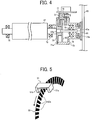
- FIG. 4 is a cross section of a rotary encoder according to the present invention provided in the driven roller 47 of the transfer belt unit 30, in an axial direction of the rotary encoder.
- the transfer belt unit 30 is comprised of the transfer belt 40, the drive roller 44 and the plurality of driven rollers 45 to 49 supporting the transfer belt 40, and a drive motor 41.
- a drive force of the drive motor 41 is transmitted to the drive roller 44 via a drive belt 42.
- Counterclockwise rotation of the drive roller 44 drives the transfer belt 40 wound on a part of the outer circumference of the drive roller 44 in a direction indicated by an arrow in the drawing.
- the driven rollers 45 to 49 contact with the transfer belt 40 and are rotated (driven) by the moving of the transfer belt 40 in the arrow direction.
- the driven roller 47 (rotary member) is integrated with the rotary encoder.
- the driven roller 47 is comprised of a roller portion contacting with the transfer belt 40 and shafts 47a to 47c.
- First bearings 70 are inserted into the shafts of both ends of the driven roller 47 so that the driven roller 47 is supported by the body of the transfer belt unit via the first bearings 70.
- Three shafts 47a to 47c with different diameters are formed on one side of the driven roller 47 (where the rotary encoder is mounted).
- the driven roller 47 can be made of stainless steel or the like.
- the rotary encoder is comprised of a code wheel 50, a transmissive photosensor 51 (encoder sensor), a support plate 71, and a cover 73.
- the cover 73 is relatively, rotatably supported on the shaft 47a of the driven roller 47 via a second bearing 74.
- the second bearing 74 is a ball bearing and its outer diameter (outer ring) is pressed into a hole of the cover 73 and its inner diameter (inner ring) is inserted with the shaft 47a.
- the cover 73 integrated with the second bearing 74 is fitted with the driven roller 47 from the right side of the FIG. 4 and positioned (in an axial direction towards the support plate 50) in contact with a stopper ring 75 of the shaft 47a.
- Axial end play of the cover 73 is eliminated by an engaging member 86 fixed to a side plate 85 of the transfer belt unit 30.
- the engaging member 86 is made of rubber material and engages with an end portion of the cover 73 fitted with the shaft 47a.
- a projection 73a of the cover 73 is fitted into a groove on the inner diameter of the engaging portion 86 to stop the rotation of the cover 73.
- the engaging member 86 biases the cover 73 towards the support plate 71, thereby eliminating the axial end play of the cover 73.
- the cover 73 has an open end on the left side of FIG. 4 into which the support plate 71 is inserted with a small gap.
- the transmissive photosensor 51 is mounted via a not-shown hole.
- the transmissive photosensor 51 fixed on a substrate 77 is mounted on the cover 73, using a nylon rivet 78 (resin rivet) after the code wheel 50, stopper ring 75, second bearing 74, and cover 73 are inserted in sequence into the shaft of the driven roller 47.
- the photosensor 51 integrated with the substrate 77 is set up to the cover 73 from above to align a through hole of the cover 73 with a long hole of a holder portion of the photosensor 51.
- the photosensor 51 is adjusted vertically to determine a position and fixed on the cover 73 with the nylon rivet 78.
- the support plate 71 is made of rubber material as polyacetal, and lightly pressed into the shaft 47b (M as press-in area, N as non press-in area in FIG. 7 ). The position of the support plate 71 is determined in the axial direction by abutting with a step between the shafts 47b, 47c with different diameters.
- the code wheel 50 is adhered to one side (opposite to press-in direction) of the support plate with a double stick tape ( FIG. 7 ).
- the code wheel 50 is made of flexible material, such as PET (polyethylene terephthalate) in thickness of about 0.2 mm and includes a radial code pattern 50a on an outer circumference of a principal surface ( FIG. 5 ). That is, a code portion is formed of alternatively, circularly arranged light transmissive areas (slits) and non-light transmissive areas (code pattern 50a) on the code wheel 50.
- the code pattern 50a of the code wheel 50 can be formed by pattern drawing technique, for example, photolithography, photoresist or etching.
- the photosensor 51 detects the code pattern 50a on the code wheel 50 to detect fluctuation in rotation speed or angle of the driven roller 47 which is concentrically rotated with the code wheel 50 (support plate 71).
- the code wheel 50 is disposed so that its outer circumference is partially placed between a light emitting portion 51a (light emitting device) and a light receiving portion 51b (light receiving device) ( FIG. 5 ).
- the code pattern 50a black portion
- the light receiving portion 51b cannot receive light from the light emitting portion 51a and it outputs a high level.
- the photosensor 51 detects the rotation of the driven roller 47 (or the code wheel 50) based on a waveform interval of an encoder output signal (obtained by converting the output of the photosensor 51), as shown in FIG. 6 .
- a control unit 80 finds the rotation speed of the driven roller 47 (or code wheel 50) as fast while the control unit 80 finds the rotation speed of the driven roller 47 (or code wheel 50) as slow based on a large waveform interval of the encoder output signal (area B in FIG. 6 ).
- the control unit 80 feeds back information on the rotation of the driven roller 47 to the drive motor 41.
- the control unit 80 accelerates drive speed of the drive motor 41 upon determining that the rotation speed of the driven roller 47 is slow.
- the control unit 80 decelerates the drive speed of the drive motor 41 upon determining that the rotation speed of the driven roller 47 is fast. This can stabilize the running speed of the transfer belt 40 of the transfer belt unit 30, thereby preventing color shifts in a color toner image formed of superimposed color toners.
- FIG. 9 shows the overall view of the code wheel 50 according to the present invention and enlarged view of points A, B on a circumferential edge portion 203a of a hole 203 (indicated by leading lines).
- the outer diameter of the code wheel 50 is set to 20 mm, and the diameter of the hole 203 is set to 4 mm (radius 2 mm).
- a ring-like mark 210 is partially shown.
- the diameter of the inner circumference 210a of the mark 210 is 4.02 mm (radius 2.01 mm), and the center position thereof coincides with that of a code portion 201 formed of a code pattern at a micron level precision.
- the code portion 201 and the mark 210 are concurrently formed by pattern drawing technique such as photolithography, photoresist, or etching.
- the hole 203 is formed after the code portion 201 and mark 210 so that its center position coincides with that of the code portion 201 and the inner circumference of the mark 210.
- gaps G1, G2 between the circumferential edge portion 203 of the hole 203 and the inner circumference of the mark 210 will be 0.01 mm (tolerance).
- the gap G1 is smaller than the gap G2 as shown in the enlarged views A, B of FIG. 9 . That is, the center position of the hole 203 is displaced upward from that of the inner circumference of the mark 210.
- FIG. 10 shows the code wheel 50 with the displacement of 0.01 mm or more.
- the gap G2 is larger than 0.01 mm.
- the displacement of the center positions between the hole 203 and the inner circumference of the mark 210 is larger than 0.01 mm and exceed a tolerance of the displacement (axial runout) of the center positions.
- the present embodiment describes an example of controlling the displacement to be smaller than 0.01 mm for the purpose of preventing color shifts in a color toner image. It is possible to easily determine whether or not the displacement is less than 0.01 mm by checking the periphery of the inner circumference and the entire circumference of the hole 203 with a magnifying glass to see if there is a gap G1 or G2 (G1, G2 > 0). That is, the code wheel in FIG. 9 with the displacement being less than 0. 01 mm is determined to be an acceptable product while that in FIG. 10 with the displacement being 0.01 mm or more is determined to be an unacceptable product. Also, it is possible to find a direction of the displacement.
- the code portion 201 and the mark 210 are precisely formed to have the same center position as described above, it is possible to determine, from a result of the above displacement determination, amount and direction of the displacement of the center positions of the code portion 201 and the hole 203.
- the diameter of the inner circumference of the mark 210 can be changed such that the higher the level of precision, the smaller the diameter.
- a tolerance of displacement for the code wheel of a rotary encoder for use in a belt carrier unit of an image forming apparatus is required to be 0.1 mm or less.
- the diameter of the inner circumference of the mark 210 need be set to 4.2 mm (radius 2.1 mm) or less which is slightly larger than that of the hole 203 (+0.2 mm or less in diameter).
- FIGs. 11A, 11B, 12A, 12B a relation between the circumferential edge portion 203a of the hole 203 and the mark 210 in the code wheel according to the present invention is described with reference to FIGs. 11A, 11B, 12A, 12B .
- the mark 210 is drawn with a very thin line and a line width thereof seems negligible; however, the mark 210 is an inner or outer circumference of a circle with a line width.
- the code wheel in FIG. 11A is an acceptable product according to the present invention since the hole 203 is contained in the mark 210 and there is a gap between the circumferential edge portion 203a of the hole 203 and the mark 210 around the enter circumferences.
- the code wheel in FIG. 11B is an unacceptable product according to the present invention since the hole 203 is not contained in the mark 210, the mark 210 is partially cut off by the hole 203 and the gap between the circumferential edge portion 203a and the mark 210 is partially eliminated.
- FIGs. 12A, 12B show the mark 210 being the outer circumference of a circle with a line width.
- the code wheel in FIG. 12A is an acceptable product according to the present invention since the hole 203 is contained in the mark 210 and there is a gap (line width) between the circumferential edge portion 203a of the hole 203 and the mark 210 (outer circumference) around the entire circumferences.
- the inner circumference of the circle with a line width coincides with the circumferential edge portion 203a of the hole 203.
- the hole 203 is contained in the mark 210 as the outer circumference and there is a gap between the circumferential edge portion 203a of the hole 203 and the mark 210 but there is also a gap between a part of an inner circumference 210a of the circle and the circumferential edge portion 203a.
- the outer circumference of the circle is the mark 210 so that this code wheel is also considered as an acceptable product according to the present invention because of the gap between the circumferential edge portion 203a and the mark 210 around the entire circumferences.
- a difference in radius between the outer circumference of the circle and the hole 203 is set to a tolerance for axial runout.
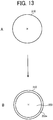
- FIG. 13 shows an example of how to form the hole 203 in the code wheel of FIG. 11A .
- the circular mark 210 reference circle
- the hole 203 is formed so as to have the same center point as that of a not-shown code portion 201 and a radius smaller than that of the hole 203 by a tolerance of a deviation in the center positions between the code portion 201 and the hole 203.
- the hole 203 is formed to be contained in the mark 210 as shown in B of FIG. 13 .
- the hole 203 can be precisely formed to be within the mark 210, or it can be roughly formed and then a code wheel having the hole 203 within the mark 210 can be selected using a magnifying glass or the like.
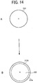
- FIG. 14 shows another example of a code wheel manufacturing method according to the present invention.
- the mark 210 reference circle
- the circular mark 210 reference circle
- the circular mark 210 is formed so as to have the same center point as that of a not-shown code portion 201 and a radius smaller than that of the hole 203 by a tolerance of a deviation in the center positions between the code portion 201 and the hole 203.
- the mark 210 is formed to be contained in the hole 203 as shown in B of FIG. 14 .
- the hole 203 can be precisely formed to be within the mark 210, or after formation of the hole 203a, a code wheel with no mark 210 remaining near the circumferential edge portion 203a of the hole 203 can be selected using a magnifying glass or the like. Code wheels with the mark 210 remaining near the circumferential edge portion 203a even partially are unacceptable products. It is preferable that an indicator (for example, *) may be added to a code wheel at a position not to be eliminated by the hole 203 in order to indicate that the code wheel is manufactured by the manufacturing method according to the present invention. This makes easier to distinguish acceptable products by just seeing the indicator and no remaining mark 210. Without the indicator, after distribution it is not able to distinguish acceptable products from other code wheels with no mark 210 manufactured by any other manufacturing method.
- an indicator for example, *
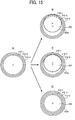
- FIG. 15 shows an example of manufacturing method for a code wheel having concentric circles, marks (reference circles) 210-1, 210-2, 210-3.
- the marks 210-1, 210-2, 210-3 have the same center point as that of the code portion 201 (not shown), and have radiuses larger than that of the hole 203 by three kinds of tolerances of deviation in the center positions between the code portion 201 and the hole 203.
- the three kinds of tolerances are set in accordance with three levels of axial runout of a code wheel.
- B, C, D of FIG. 15 are acceptable code wheels with holes 203 formed by the method in FIG. 13 .
- the hole 203 of the code wheel C of FIG. 15 is partially overlapped with the mark 210-1 and corresponds with a medium level tolerance of the three tolerances. Accordingly, it is a code wheel with medium level axial runout of the code portion 201.
- the hole 203 of the code wheel B of FIG. 15 is partially overlapped with the mark 210-2 and corresponds with a largest tolerance of the three tolerances. Accordingly, it is a code wheel with largest axial runout of the code portion 201.
- the code wheel B is also an acceptable product with axial runout within the third tolerance.
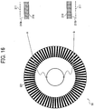
- FIG. 16 shows the overall view of the code wheel 50 before the hole 203 is formed and enlarged views of points A, B (indicated by leading lines).
- the outer diameter of the code wheel 50 is set to 20 mm, and the diameter of the hole 203 to be formed is set to 4 mm (radius 2mm).
- a target position of the circumferential edge portion 203 of the hole 203 is indicated by a broken line 211 and a ring-like mark 210 is shown in the enlarged views.
- the diameter of an outer circumference 210b of the mark 210 is 3.98 mm (radius 1.99 mm), and the center position thereof coincides with that of the code portion 201 at a micron level precision.
- the code portion 201 and the mark 210 are concurrently formed by pattern drawing technique such as photolithography, photoresist, or etching. After formation of the code portion 201 and the mark 210, the hole 203 is formed so that its center position coincides with that of the code portion 201 and the mark 210.
- FIG. 17 shows the code wheel 50 after the hole 203 is formed and enlarged views of points A, B of the circumferential edge portion 203a. It is seen from the enlarged views that the mark 210 is eliminated. The entire outer circumference of the mark 210 will be eliminated when displacement of the center positions between the hole 203 and the mark 210 is less than 0.01mm.
- FIG. 18 shows the code wheel 50 with the displacement of the center positions being 0.01mm or more. As seen in the enlarged view of point B, the mark 210 is present because the center position of the hole 203 is displaced from that of the outer circumference of the mark 210 by 0.01 mm or more in an upward direction in FIG. 18 . Accordingly, this code wheel 50 is determined to be an unacceptable product according to the manufacturing method of the present invention.
- the displacement it is possible to determine the displacement to be less than 0.01 mm by simply checking that the mark 210 is eliminated all around the inner circumference of the hole 203 using a magnifying glass or the like. With the displacement being 0.01mm or more, a direction of the displacement can be also determined.
- the code portion 201 and the mark 210 are precisely formed to have the same center position as described above, it is possible to determine, from a result of the above displacement determination, amount and direction of the displacement of the center positions of the code portion 201 and the hole 203.
- the diameter of the outer circumference of the mark 210 can be set such that the higher the level, the larger the diameter.
- a tolerance of the above displacement is required to be less than 0.1 mm.
- the diameter of the outer circumference of the mark 210 need be set to 3.8 mm (radius 1.9 mm) or more which is slightly smaller than that of the hole 203 (-0.2 mm or less in diameter).
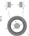
- the diameter of the inner circumference of the mark 210 can be set to 0 mm (with no inner circumference) as shown in the code wheel 50 before formation of the hole 203 in FIG. 19 .
- the code wheel 50 after the formation of the hole 203 will be the same as that in FIGs. 17 , 18 .
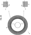
- FIG. 20 shows the overall view of the code wheel 50 before the hole 203 is formed and enlarged views of points A, B.
- the outer diameter of the code wheel 50 is set to 20 mm, and the diameter of the hole 203 to be formed is set to 4 mm (radius 2 mm).
- a target position of the circumferential edge portion 203a of the hole 203 is indicated by a broken line 211 and a ring-like mark 210 is shown in the enlarged views.
- the diameter of an inner circumference 210a of the mark 210 is 3.98 mm (radius 1.99 mm), and the center position thereof coincides with that of the code portion 201 at a micron level precision.
- the code portion 201 and the mark 210 are concurrently formed by pattern drawing technique such as photolithography, photoresist, or etching. After formation of the code portion 201 and the mark 210, the hole 203 is formed so that its center position coincides with that of the code portion 201 and the mark 210.
- FIG. 21 shows the code wheel 50 after the hole 203 is formed and enlarged views of points A, B of the circumferential edge portion 203a. It can be seen from the enlarged view of point B that there is a gap G2 between the circumferential edge portion 203a of the hole 203 and the inner circumference 210a of the mark 210. But, there is no gap in the enlarged view of point A. With a displacement being 0.01 mm or more between the center positions of the hole 203 and the inner circumference of the mark 210, a gap will occur near the circumferential edge portion 203a of the hole 203.
- FIG. 21 shows the code wheel 50 after the hole 203 is formed and enlarged views of points A, B of the circumferential edge portion 203a.
- FIG. 21 shows that the center position of the hole 203 is displaced from that of the inner circumference of the mark 210 by 0.01 mm or more in an upward direction in FIG. 21 . With the displacement being less than 0.01mm, there will be no gap as shown in FIG. 22 .
- the displacement it is possible to determine the displacement to be less than 0.01 mm by simply checking around the entire circumference of the hole 203 that the gap G2 or G1 is present (G1, G2 > 0). With the displacement being 0.01 mm or more, a direction of the displacement can be determined.
- the code portion 201 and the mark 210 are precisely formed to have the same center position as described above, it is possible to determine, from a result of the above displacement determination, amount and direction of the displacement of the center positions of the code portion 201 and the hole 203.
- the diameter of the inner circumference of the mark 210 can be set such that the higher the level, the larger the diameter.
- a tolerance of the above displacement is required to be less than 0.1 mm.
- the diameter of the outer circumference of the mark 210 need be set to 3.8 mm (radius 1.9 mm) or more which is slightly smaller than that of the hole 203 (-0.2 mm or less in diameter).
- FIG. 23 shows the overall view of the code wheel 50 before the hole 203 is formed and enlarged views of points A, B.
- the outer diameter of the code wheel 50 is set to 20 mm, and the diameter of the hole 203 to be formed is set to 4 mm (radius 2mm).
- a target position of the circumferential edge portion 203 of the hole 203 is indicated by a broken line 211 and the ring-like mark 210 is shown in the enlarged views.
- the diameter of an outer circumference 210b of the mark 210 is 4.02 mm (radius 2.01 mm), and the center position thereof coincides with that of the code portion 201 at a micron level precision.
- the code portion 201 and the mark 210 are concurrently formed by pattern drawing technique such as photolithography, photoresist, or etching. After formation of the code portion 201 and the mark 210, the hole 203 is formed so that its center position coincides with that of the code portion 201 and the mark 210.
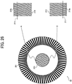
- FIG. 24 shows the code wheel 50 after the hole 203 is formed and enlarged views of points A, B of the circumferential edge portion 203a.
- the mark 210 is seen in both the enlarged views.
- the mark 210 will remain around the entire circumference of the hole 203 when displacement of the center positions between the hole 203 and the outer circumference of mark 210 is less than 0.01 mm.
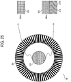
- FIG. 25 shows the code wheel 50 with the displacement of the center positions being 0.01 mm or more.
- the mark 210 is eliminated because the center position of the hole 203 is displaced from that of the outer circumference of the mark 210 by 0.01 mm or more in an upward direction in the drawing.
- the displacement it is possible to determine the displacement to be less than 0.01 mm by simply checking that the mark 210 is eliminated all around the inner circumference of the hole 203 using a magnifying glass or the like. With the displacement being 0.01 mm or more, a direction of the displacement can be determined.
- the code portion 201 and the mark 210 are precisely formed to have the same center position as described above, it is possible to determine, from a result of the above displacement determination, amount and direction of the displacement of the center positions of the code portion 201 and the hole 203.
- the diameter of the outer circumference of the mark 210 can be set such that the higher the level, the smaller the diameter. Generally, a tolerance of the above displacement is required to be less than 0.1 mm. Accordingly, the diameter of the outer circumference of the mark 210 need be set to 4.2 mm (radius 2.1 mm) or less which is slightly larger than that of the hole 203 (+0.2 mm or less in diameter).
- the diameter of the inner circumference of the mark 210 can be set to 0 mm (with no inner circumference) as shown in the code wheel 50 before formation of the hole 203 in FIG. 26 .
- the code wheel 50 after the formation of the hole 203 will be the same as that in FIGs. 24 , 25 .
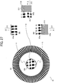
- FIG. 27 shows the code wheel 50 in the same state as that in FIG. 25 , and enlarged views of points A, B, C.
- an indicator 212 with 12 evenly divided scales and numerals 1 to 12 is provided to indicate a position in a circumferential direction.
- three numerals 12, 3, 6 of the indicator 212 are shown.
- the rest of the fifth embodiment is the same as the fourth embodiment.
- the code portion 201 and the mark 210 are precisely formed to have the same center position as described above, it is possible to determine, from a result of the above displacement determination, amount and direction of the displacement of the center positions of the code portion 201 and the hole 203.
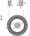
- a code wheel 50 according to the sixth embodiment of the present invention is described with reference to FIG. 28 .
- the present embodiment is different from the second embodiment that the mark 210 (reference circle) is formed in an evenly intermittent circle in the circumference direction.
- FIG. 28 shows the code wheel 50 in the same state as that in FIG. 18 and enlarged view of points A, B.
- a mark 210c is evenly divided in the circumference direction.
- the rest of the sixth embodiment is the same as the second embodiment.
- the intermittent mark 210c With a displacement of the center positions between the hole 203 and the outer circumference of the mark 210c being 0.01 mm or more, the intermittent mark 210c will be seen as in the enlarged view B of FIG. 28 .
- a remaining portion of the mark 210c around the circumference of the hole 203 changes, that is, the number of strips of the intermittent mark 210c changes such that the larger the displacement, the larger the number of strips. Therefore, by counting the number of strips of the mark 210, the amount of the displacement can be obtained.
- the code portion 201 and the mark 210 are precisely formed to have the same center position as described above, it is possible to determine, from a result of the above displacement determination, amount and direction of the displacement of the center positions of the code portion 201 and the hole 203.
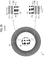
- FIG. 29 shows the code wheel 50 in the same state as that in FIG. 9 and enlarged views of points A, B.
- the mark 210 is composed of two circles, 210-1 and 201-2.
- the outer diameter of the code wheel 50 is set to 20 mm and the diameter of the hole 203 is set to 4mm (radius 2 mm) as in FIG. 9 .
- the diameter of the inner circumference 210-1a of the mark 210-1 is 4.01 mm (radius 2.005 mm) and that of the outer circumference 210-1b of the mark 210-1 is 4.02 mm (radius 2.01 mm) while the diameter of the inner circumference 210-2a of the mark 210-2 is 4.03mm (radius 2.015 mm) and that of the outer circumference 210-2b of the mark 210-2 is 4.04mm (radius 2.02 mm).
- Their respective center positions all coincide with that of the code portion 201 at a micron level precision.
- the hole 203 is formed after formation of the code portion 201 and the mark 210 so that its center position coincides with that of the code portion 201 and that of the inner circumference of the mark 210.
- FIG. 30 shows the code wheel 50 with the displacement being 0.005 mm or more and 0.01 mm or less.
- the gap G1 is eliminated (the hole 203 is displaced in an upward direction in FIG. 30 ).
- FIG. 31 shows the code wheel 50 with the displacement being 0.01 mm or more and 0.015 mm or less.
- the mark 201-1 is eliminated (the hole 203 is displaced in an upward direction in FIG. 31 ).
- FIG. 32 shows the code wheel with the displacement being 0.015 mm or more and 0.020 mm or less.
- the gap G3 is eliminated (the hole is displaced in an upward direction in FIG. 32 ).
- FIG. 33 shows the code wheel 50 with the displacement being 0.02 mm or more.
- the mark 201-2 is eliminated (the hole is displaced in an upward direction in FIG. 33 ).
- the amount of displacement of the hole 203a can be determined in a range of 0 to 0.02 mm with 0.005 mm increments. Accordingly, it is possible to select a code wheel with a displacement within a desired tolerance and to manufacture code wheels at different quality levels.
- the code portion 201 and the mark 210 are precisely formed to have the same center position as described above, it is possible to determine, from a result of the above displacement determination, amount and direction of the displacement of the center positions of the code portion 201 and the hole 203.
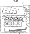
- FIG. 34 shows the overall structure of an image forming apparatus. This image forming apparatus is similar to that in FIG. 1 so that a difference between the two is mainly described.
- While the image forming apparatus in FIG. 1 is configured to carry paper P via the transfer belt 40 to the transfer rollers 24 to sequentially transfer toner images in the four colors on the photoconductor drums 21 to the paper P, that in FIG. 34 is configured to temporarily transfer toner images in the four colors to the transfer belt 40 (intermediate transfer belt) at positions opposite to the transfer rollers 24.
- the paper P from a paper feed unit 61 passes a carrier guide 63 and is carried at a good timing via a resist roller pair 64 to a gap between a transfer roller 65 and the transfer belt 40.
- the toner images transferred onto the transfer belt 40 is then transferred onto the paper P.
- This image forming apparatus also comprises a belt carrier unit including a rotary encoder with the code wheel according to any of the first to seventh embodiments as that in FIG. 1 .
- the rest of the structure and operation thereof is the same as that in FIG. 1 so that a description thereon is omitted.
- the above-described embodiments can be freely combined according to an object to achieve such as a size of the hole or an amount of displacement (concentricity) to control or determine.
- the first to seventh embodiments have described an example that the code wheel 50 is made of rubber material as polyacetal and the code portion 201 is read with the transmissive photosensor 51.
- the code wheel 50 can be made of metal material as stainless and the code portion 201 can be read with a reflective photosensor.
- the present invention is applied to the transfer belt unit 30 (belt carrier unit) incorporating the transfer belt 40.
- application of the present invention is not limited thereto.
- the present invention is applicable to a belt carrier unit (transfer belt unit) using a transfer belt, a belt carrier unit (photoreceptor belt unit) using a photoreceptor belt or the like. Also, in this case the same effects as those of the above embodiments are attainable by mounting the rotary encoder of any of the above embodiments in a belt carrier roller (drive or driven roller) which contacts with a transfer belt or a photoreceptor belt.
- the rotary encoder is mounted in the driven roller 47 on which the transfer belt 40 is wound, aiming for stabilizing movability of the transfer belt 40.
- the rotary encoder can be mounted in any other rolling member to directly control rotation of the rolling member.
- the rotary encoder according to any of the above embodiments can be integrally mounted on the shaft of the photoconductor drum 21 to control rotation thereof (feedback control). In this case, the same effects as those in the above embodiments are also attainable.
- the present invention can achieve a code wheel manufacturing method without a complex, time consuming hole forming process or a large-scale inspection, a code wheel which can be examined easily in quality and is manufactured by the above manufacturing method, a rotary encoder incorporating such a code wheel, and a rotation control unit, a belt carrier unit and an image forming apparatus incorporating such a rotary encoder.
- the code wheel according to the present invention can be easily examined in a short time by anyone in any place with a magnifying glass without a specific device as a microscope or a projector.
- the amount and direction of displacement of the center positions of the code portion and the hole can be determined in any field site other than a manufacturing facility provided with expensive equipment.
- the code wheel manufacturing method according to the present invention makes it possible to perform, easily and in a shorter period of time, quality control over rotary encoder products or problem analysis when it occurs.
- the rotary encoder, rotation control unit, belt carrier unit, and image forming apparatus according to the present invention comprise a non-expensive, high quality code wheel according to the present invention so that maintenance and repair of the code wheel can be facilitated.
Landscapes
- Physics & Mathematics (AREA)
- General Physics & Mathematics (AREA)
- Transmission And Conversion Of Sensor Element Output (AREA)
- Electrophotography Configuration And Component (AREA)
- Optical Transform (AREA)
- Electrostatic Charge, Transfer And Separation In Electrography (AREA)
- Discharging, Photosensitive Material Shape In Electrophotography (AREA)
- Color Electrophotography (AREA)
Claims (16)
- Herstellungsverfahren für ein Kodierrad (50) für einen Drehcodierer, wobei das Kodierrad (50) in einem zentralen Abschnitt ein Loch (203), in das eine Drehwelle eines Drehelements (47) eingepasst ist, und einen Kodierungsabschnitt (201) umfasst, der ein radiales Kodemuster in einem Umfangsrandabschnitt umfasst, wobei das Verfahren die folgenden Schritte umfasst:Bilden des Kodierungsabschnitts (201) und eines Teilkreises (210) in einer Platte, sodass der Teilkreis (210) einen um eine Abweichungstoleranz größeren Radius hat als ein Radius des Lochs (203) zwischen einer zentralen Position des Kodierungsabschnitts (201) und einer zentralen Position des Lochs (203), und wobei der Teilkreis (210) ein gleiches Zentrum hat wie das des Kodierungsabschnitts (201); undBilden des Lochs (203) in der Platte, in der der Kodierungsabschnitt (201) und der Teilkreis (210) gebildet sind, beruhend auf dem Teilkreis (210).
- Herstellungsverfahren nach Anspruch 1, wobei
beim Schritt des Bildens des Lochs das Loch (203) so gebildet ist, dass es im Teilkreis (210) enthalten ist. - Herstellungsverfahren nach Anspruch 1, wobei
beim Schritt des Bildens des Lochs das Loch (203) so gebildet ist, dass der Teilkreis (210) eliminiert ist. - Herstellungsverfahren nach einem der Ansprüche 1 bis 3, wobei:der Schritt des Bildens des Teilkreises einen Schritt des Bildens einer Vielzahl von Teilkreisen (210) in Übereinstimmung mit einer Vielzahl von Abweichungstoleranzen umfasst; undder Schritt des Bildens des Lochs einen Schritt des Auswählens eines Teilkreises (210) von der Vielzahl von Teilkreisen (210) in Übereinstimmung mit einer festgelegten Abweichungstoleranz umfasst.
- Herstellungsverfahren nach einem der Ansprüche 1 bis 4, wobei unter der Vielzahl von Teilkreisen (210) zumindest angrenzende Teilkreise (210) in unterschiedlichen Farben gebildet sind.
- Herstellungsverfahren für einen Drehcodierer, umfassend:Herstellen eines Kodierrads (50) nach dem Verfahren nach einem der Ansprüche 1 bis 5; undAnordnen des Kodierrads mit einem Kodierungssensor (51).
- Herstellungsverfahren für eine Drehsteuereinheit, umfassend:Herstellen eines Drehcodierers nach dem Verfahren nach Anspruch 6; undBereitstellen des Drehcodierers mit einem Rückkopplungssteuermechanismus, konfiguriert, eine Drehung des Drehelements (47) in Übereinstimmung mit der vom Drehcodierer gemessenen Drehgeschwindigkeit zu steuern.
- Herstellungsverfahren für eine Riementrägereinheit (30), die ein Element (P) durch Bewegen eines Riemens, der sich bis zum Drehelement erstreckt, trägt, umfassend:Bereitstellen der Riementrägereinheit (30) mit einer Drehsteuerungseinheit, hergestellt nach Anspruch 7.
- Herstellungsverfahren für eine Bildgebungsvorrichtung, umfassend:Bereitstellen der Bildgebungsvorrichtung mit einer Riementrägereinheit (30), hergestellt nach Anspruch 8, zum Tragen eines Elements (P), auf dem ein Bild gebildet ist.
- Kodierrad (50) für einen Drehcodierer, umfassend:ein Loch (203), in das eine Drehwelle eines Drehelements (47) eingepasst ist, in einer zentralen Position;einen Kodierungsabschnitt (201), umfassend ein radiales Kodemuster in einem Umfangsrandabschnitt (203a); undeinen Teilkreis (210) mit einem gleichen Zentrum wie das des Kodierungsabschnitts (201) und mit einem um eine Abweichungstoleranz größeren Radius als ein Radius des Lochs (203) zwischen einer zentralen Position des Kodierungsabschnitts (201) und einer zentralen Position des Lochs (203).
- Kodierrad (50) nach Anspruch 10, wobei
der Teilkreis (210) ein Außenumfang oder ein Innenumfang eines Rings mit einer Breite ist. - Kodierrad (50) nach einem der Ansprüche 10 oder 11, wobei der Teilkreis (210) mit Unterbrechungen in eine Umfangsrichtung gebildet ist.
- Drehcodierer, umfassend:das Kodierrad (50) nach einem der Ansprüche 10 bis 12; undeinen Kodierungssensor (51).
- Drehsteuereinheit, umfassend:den Drehcodierer nach Anspruch 13, der eine Drehgeschwindigkeit des Drehelements (47) misst; undeinen Rückkopplungssteuermechanismus, der eine Drehung des Drehelements (47) in Übereinstimmung mit der vom Drehcodierer gemessenen Drehgeschwindigkeit steuert.
- Riementrägereinheit (30), die ein Element (P) durch das Bewegen eines Riemens, der sich bis zum Drehelement (47) erstreckt, trägt, umfassend:die Drehsteuereinheit nach Anspruch 14.
- Bildgebungsvorrichtung, umfassend die Riementrägereinheit (30) nach Anspruch 15 zum Tragen eines Elements (P), auf dem ein Bild gebildet ist.
Applications Claiming Priority (1)
| Application Number | Priority Date | Filing Date | Title |
|---|---|---|---|
| JP2008102326A JP5132398B2 (ja) | 2008-04-10 | 2008-04-10 | パルスコードホイールの製造方法、パルスコードホイール、ロータリーエンコーダ、回転制御装置、ベルト搬送装置、及び画像形成装置 |
Publications (3)
| Publication Number | Publication Date |
|---|---|
| EP2108926A2 EP2108926A2 (de) | 2009-10-14 |
| EP2108926A3 EP2108926A3 (de) | 2015-11-25 |
| EP2108926B1 true EP2108926B1 (de) | 2017-09-20 |
Family
ID=40848803
Family Applications (1)
| Application Number | Title | Priority Date | Filing Date |
|---|---|---|---|
| EP09250813.4A Not-in-force EP2108926B1 (de) | 2008-04-10 | 2009-03-24 | Kodierrad-Herstellungsverfahren, Kodierrad, Drehcodierer, Drehsteuereinheit, Riementrägereinheit und Bildgebungsvorrichtung |
Country Status (4)
| Country | Link |
|---|---|
| US (1) | US8264380B2 (de) |
| EP (1) | EP2108926B1 (de) |
| JP (1) | JP5132398B2 (de) |
| CN (1) | CN101692003B (de) |
Families Citing this family (13)
| Publication number | Priority date | Publication date | Assignee | Title |
|---|---|---|---|---|
| JP5463926B2 (ja) * | 2010-01-15 | 2014-04-09 | 富士ゼロックス株式会社 | 回転体異常検出装置および画像形成装置 |
| CN102846330B (zh) * | 2011-06-30 | 2015-09-30 | 上海西门子医疗器械有限公司 | 一种自适应加速度补偿装置和方法 |
| JP2015124044A (ja) * | 2013-12-26 | 2015-07-06 | セイコーエプソン株式会社 | ベルト搬送装置、媒体搬送装置ならびにプリンター |
| JP6494303B2 (ja) | 2015-01-26 | 2019-04-03 | キヤノンプレシジョン株式会社 | ロータリースケールの製造方法 |
| JP6425585B2 (ja) * | 2015-03-03 | 2018-11-21 | キヤノン株式会社 | 記録装置及び制御方法 |
| CN105716637B (zh) * | 2016-03-10 | 2018-03-30 | 华中科技大学 | 一种光学编码器 |
| CN107193321B (zh) * | 2017-05-25 | 2018-10-12 | 中国铁道科学研究院 | 基于图像识别的手柄式位置控制装置 |
| DE102018107653A1 (de) * | 2018-03-29 | 2019-10-02 | Frank Hohmann | Vorrichtung zum Anziehen von Schraubverbindungen |
| CN112444277A (zh) | 2019-09-04 | 2021-03-05 | 台达电子工业股份有限公司 | 光学反射部件及其适用的光学编码器 |
| KR102836005B1 (ko) * | 2019-11-08 | 2025-07-18 | 가부시끼가이샤 산쿄 세이사쿠쇼 | 회전 위치 결정 장치 |
| CN113888795B (zh) * | 2021-12-08 | 2022-04-01 | 恒银金融科技股份有限公司 | 可调整式摆动挡钞机构及自动取款机 |
| JP7771805B2 (ja) * | 2022-02-16 | 2025-11-18 | セイコーエプソン株式会社 | 回転検出装置、媒体搬送装置および記録装置 |
| US12054359B1 (en) * | 2023-07-12 | 2024-08-06 | Otis Elevator Company | Roller guide mounted elevator monitoring systems |
Family Cites Families (12)
| Publication number | Priority date | Publication date | Assignee | Title |
|---|---|---|---|---|
| JPS6427827A (en) | 1987-07-20 | 1989-01-30 | Aronshiya Kk | Encoder disc |
| JPH06194185A (ja) | 1992-12-25 | 1994-07-15 | Ishikawajima Harima Heavy Ind Co Ltd | ロータリーエンコーダ |
| GB2299403B (en) * | 1994-08-25 | 1999-04-07 | Braun Paul W | Timing scale or timing disc |
| JPH0979867A (ja) * | 1995-09-11 | 1997-03-28 | Canon Inc | 光学式エンコーダースケールの製造方法及び光学式エンコーダースケールの製造装置 |
| EP1016854B1 (de) * | 1996-03-04 | 2003-06-25 | Alps Electric Co., Ltd. | Kodiererplatte für Rotationssensor |
| JP2004340929A (ja) * | 2003-04-21 | 2004-12-02 | Mitsubishi Electric Corp | 光学式ロータリーエンコーダ |
| JP4339079B2 (ja) * | 2003-10-31 | 2009-10-07 | 株式会社リコー | 転写ベルトの速度制御方法及び転写ベルトの速度制御装置及びこれを用いた画像形成装置 |
| JP2006292724A (ja) * | 2005-03-17 | 2006-10-26 | Ricoh Co Ltd | 回転角検出装置、回転角検出装置の製造装置、回転角検出装置の製造方法、記録媒体および画像形成装置 |
| JP4530280B2 (ja) * | 2005-04-25 | 2010-08-25 | 株式会社リコー | ロータリエンコーダ、ローラ部材、ベルト搬送装置、及び、画像形成装置 |
| JP4530281B2 (ja) | 2005-04-25 | 2010-08-25 | 株式会社リコー | ロータリエンコーダ、ローラ部材、ベルト搬送装置、及び、画像形成装置 |
| DE202006019989U1 (de) * | 2006-08-31 | 2007-08-02 | Sick Stegmann Gmbh | Metallcodescheibe mit Federelementen |
| JP4908329B2 (ja) * | 2007-06-28 | 2012-04-04 | 株式会社リコー | 被検知体の移動速度制御装置、光学式エンコーダの製造方法及び画像形成装置 |
-
2008
- 2008-04-10 JP JP2008102326A patent/JP5132398B2/ja not_active Expired - Fee Related
-
2009
- 2009-03-24 EP EP09250813.4A patent/EP2108926B1/de not_active Not-in-force
- 2009-04-03 US US12/385,283 patent/US8264380B2/en not_active Expired - Fee Related
- 2009-04-10 CN CN2009101299382A patent/CN101692003B/zh not_active Expired - Fee Related
Non-Patent Citations (1)
| Title |
|---|
| None * |
Also Published As
| Publication number | Publication date |
|---|---|
| EP2108926A2 (de) | 2009-10-14 |
| JP2009250921A (ja) | 2009-10-29 |
| CN101692003B (zh) | 2011-10-12 |
| JP5132398B2 (ja) | 2013-01-30 |
| US20090256309A1 (en) | 2009-10-15 |
| CN101692003A (zh) | 2010-04-07 |
| EP2108926A3 (de) | 2015-11-25 |
| US8264380B2 (en) | 2012-09-11 |
Similar Documents
| Publication | Publication Date | Title |
|---|---|---|
| US8264380B2 (en) | Code wheel manufacturing method, code wheel, rotary encoder, rotation control unit, belt carrier unit, and image forming apparatus | |
| US7110687B2 (en) | Image forming device | |
| US7369795B2 (en) | Image forming apparatus effectively producing quality color image without causing color slippage | |
| US7239833B2 (en) | Image forming device and color misregistration correction method for image forming device | |
| EP1031887A2 (de) | Bilerzeugungsgerät und Program | |
| US20090022504A1 (en) | Image forming apparatus, image carrier, and process cartridge | |
| US20100239329A1 (en) | Image forming apparatus | |
| EP2945018B1 (de) | Sensorvorrichtung, bilderzeugungsvorrichtung und steuerungsverfahren für lichtquelle | |
| CN103389636B (zh) | 用于执行配准和浓度校正控制的图像形成装置 | |
| JP5287168B2 (ja) | 回転円板の偏心測定方法 | |
| US20100166444A1 (en) | Image forming apparatus and image forming method | |
| US7460820B2 (en) | Drive control device and image forming apparatus | |
| US20110262183A1 (en) | Image device and image forming apparatus | |
| CN102163020A (zh) | 光学传感器和包含该光学传感器的成像设备 | |
| CN118963085A (zh) | 转印单元和具备转印单元的图像形成装置 | |
| JP2000075593A (ja) | 多色画像形成装置 | |
| JP5954580B2 (ja) | 画像形成装置 | |
| CN100431333C (zh) | 用于图像形成设备的带控制装置 | |
| US7536143B2 (en) | Method and apparatus for image forming for effectively adjusting phase differences of image bearing members | |
| JPH05119571A (ja) | カラー画像形成装置 | |
| JP2006300871A (ja) | ロータリエンコーダ、ローラ部材、ベルト搬送装置、及び、画像形成装置 | |
| US7061616B2 (en) | Optical transceiver and method for image density measurement | |
| JP2013088642A (ja) | 画像形成装置 | |
| JP3515869B2 (ja) | 画像形成装置 | |
| JPH11338216A (ja) | カラー画像形成装置 |
Legal Events
| Date | Code | Title | Description |
|---|---|---|---|
| PUAI | Public reference made under article 153(3) epc to a published international application that has entered the european phase |
Free format text: ORIGINAL CODE: 0009012 |
|
| AK | Designated contracting states |
Kind code of ref document: A2 Designated state(s): AT BE BG CH CY CZ DE DK EE ES FI FR GB GR HR HU IE IS IT LI LT LU LV MC MK MT NL NO PL PT RO SE SI SK TR |
|
| AX | Request for extension of the european patent |
Extension state: AL BA RS |
|
| PUAL | Search report despatched |
Free format text: ORIGINAL CODE: 0009013 |
|
| AK | Designated contracting states |
Kind code of ref document: A3 Designated state(s): AT BE BG CH CY CZ DE DK EE ES FI FR GB GR HR HU IE IS IT LI LT LU LV MC MK MT NL NO PL PT RO SE SI SK TR |
|
| AX | Request for extension of the european patent |
Extension state: AL BA RS |
|
| RIC1 | Information provided on ipc code assigned before grant |
Ipc: G01D 5/347 20060101AFI20151019BHEP |
|
| 17P | Request for examination filed |
Effective date: 20160128 |
|
| RBV | Designated contracting states (corrected) |
Designated state(s): AT BE BG CH CY CZ DE DK EE ES FI FR GB GR HR HU IE IS IT LI LT LU LV MC MK MT NL NO PL PT RO SE SI SK TR |
|
| AKX | Designation fees paid |
Designated state(s): AT BE BG CH CY CZ DE DK EE ES FI FR GB GR HR HU IE IS IT LI LT LU LV MC MK MT NL NO PL PT RO SE SI SK TR |
|
| AXX | Extension fees paid |
Extension state: BA Extension state: AL Extension state: RS |
|
| GRAP | Despatch of communication of intention to grant a patent |
Free format text: ORIGINAL CODE: EPIDOSNIGR1 |
|
| STAA | Information on the status of an ep patent application or granted ep patent |
Free format text: STATUS: GRANT OF PATENT IS INTENDED |
|
| INTG | Intention to grant announced |
Effective date: 20170406 |
|
| GRAS | Grant fee paid |
Free format text: ORIGINAL CODE: EPIDOSNIGR3 |
|
| GRAA | (expected) grant |
Free format text: ORIGINAL CODE: 0009210 |
|
| STAA | Information on the status of an ep patent application or granted ep patent |
Free format text: STATUS: THE PATENT HAS BEEN GRANTED |
|
| AK | Designated contracting states |
Kind code of ref document: B1 Designated state(s): AT BE BG CH CY CZ DE DK EE ES FI FR GB GR HR HU IE IS IT LI LT LU LV MC MK MT NL NO PL PT RO SE SI SK TR |
|
| REG | Reference to a national code |
Ref country code: GB Ref legal event code: FG4D |
|
| REG | Reference to a national code |
Ref country code: CH Ref legal event code: EP |
|
| REG | Reference to a national code |
Ref country code: AT Ref legal event code: REF Ref document number: 930527 Country of ref document: AT Kind code of ref document: T Effective date: 20171015 |
|
| REG | Reference to a national code |
Ref country code: IE Ref legal event code: FG4D |
|
| REG | Reference to a national code |
Ref country code: DE Ref legal event code: R096 Ref document number: 602009048419 Country of ref document: DE |
|
| REG | Reference to a national code |
Ref country code: NL Ref legal event code: MP Effective date: 20170920 |
|
| PG25 | Lapsed in a contracting state [announced via postgrant information from national office to epo] |
Ref country code: SE Free format text: LAPSE BECAUSE OF FAILURE TO SUBMIT A TRANSLATION OF THE DESCRIPTION OR TO PAY THE FEE WITHIN THE PRESCRIBED TIME-LIMIT Effective date: 20170920 Ref country code: HR Free format text: LAPSE BECAUSE OF FAILURE TO SUBMIT A TRANSLATION OF THE DESCRIPTION OR TO PAY THE FEE WITHIN THE PRESCRIBED TIME-LIMIT Effective date: 20170920 Ref country code: LT Free format text: LAPSE BECAUSE OF FAILURE TO SUBMIT A TRANSLATION OF THE DESCRIPTION OR TO PAY THE FEE WITHIN THE PRESCRIBED TIME-LIMIT Effective date: 20170920 Ref country code: FI Free format text: LAPSE BECAUSE OF FAILURE TO SUBMIT A TRANSLATION OF THE DESCRIPTION OR TO PAY THE FEE WITHIN THE PRESCRIBED TIME-LIMIT Effective date: 20170920 Ref country code: NO Free format text: LAPSE BECAUSE OF FAILURE TO SUBMIT A TRANSLATION OF THE DESCRIPTION OR TO PAY THE FEE WITHIN THE PRESCRIBED TIME-LIMIT Effective date: 20171220 |
|
| REG | Reference to a national code |
Ref country code: LT Ref legal event code: MG4D |
|
| REG | Reference to a national code |
Ref country code: AT Ref legal event code: MK05 Ref document number: 930527 Country of ref document: AT Kind code of ref document: T Effective date: 20170920 |
|
| PG25 | Lapsed in a contracting state [announced via postgrant information from national office to epo] |
Ref country code: GR Free format text: LAPSE BECAUSE OF FAILURE TO SUBMIT A TRANSLATION OF THE DESCRIPTION OR TO PAY THE FEE WITHIN THE PRESCRIBED TIME-LIMIT Effective date: 20171221 Ref country code: LV Free format text: LAPSE BECAUSE OF FAILURE TO SUBMIT A TRANSLATION OF THE DESCRIPTION OR TO PAY THE FEE WITHIN THE PRESCRIBED TIME-LIMIT Effective date: 20170920 Ref country code: BG Free format text: LAPSE BECAUSE OF FAILURE TO SUBMIT A TRANSLATION OF THE DESCRIPTION OR TO PAY THE FEE WITHIN THE PRESCRIBED TIME-LIMIT Effective date: 20171220 |
|
| PG25 | Lapsed in a contracting state [announced via postgrant information from national office to epo] |
Ref country code: NL Free format text: LAPSE BECAUSE OF FAILURE TO SUBMIT A TRANSLATION OF THE DESCRIPTION OR TO PAY THE FEE WITHIN THE PRESCRIBED TIME-LIMIT Effective date: 20170920 |
|
| REG | Reference to a national code |
Ref country code: FR Ref legal event code: PLFP Year of fee payment: 10 |
|
| PG25 | Lapsed in a contracting state [announced via postgrant information from national office to epo] |
Ref country code: RO Free format text: LAPSE BECAUSE OF FAILURE TO SUBMIT A TRANSLATION OF THE DESCRIPTION OR TO PAY THE FEE WITHIN THE PRESCRIBED TIME-LIMIT Effective date: 20170920 Ref country code: CZ Free format text: LAPSE BECAUSE OF FAILURE TO SUBMIT A TRANSLATION OF THE DESCRIPTION OR TO PAY THE FEE WITHIN THE PRESCRIBED TIME-LIMIT Effective date: 20170920 Ref country code: PL Free format text: LAPSE BECAUSE OF FAILURE TO SUBMIT A TRANSLATION OF THE DESCRIPTION OR TO PAY THE FEE WITHIN THE PRESCRIBED TIME-LIMIT Effective date: 20170920 Ref country code: ES Free format text: LAPSE BECAUSE OF FAILURE TO SUBMIT A TRANSLATION OF THE DESCRIPTION OR TO PAY THE FEE WITHIN THE PRESCRIBED TIME-LIMIT Effective date: 20170920 |
|
| PG25 | Lapsed in a contracting state [announced via postgrant information from national office to epo] |
Ref country code: SK Free format text: LAPSE BECAUSE OF FAILURE TO SUBMIT A TRANSLATION OF THE DESCRIPTION OR TO PAY THE FEE WITHIN THE PRESCRIBED TIME-LIMIT Effective date: 20170920 Ref country code: AT Free format text: LAPSE BECAUSE OF FAILURE TO SUBMIT A TRANSLATION OF THE DESCRIPTION OR TO PAY THE FEE WITHIN THE PRESCRIBED TIME-LIMIT Effective date: 20170920 Ref country code: IT Free format text: LAPSE BECAUSE OF FAILURE TO SUBMIT A TRANSLATION OF THE DESCRIPTION OR TO PAY THE FEE WITHIN THE PRESCRIBED TIME-LIMIT Effective date: 20170920 Ref country code: EE Free format text: LAPSE BECAUSE OF FAILURE TO SUBMIT A TRANSLATION OF THE DESCRIPTION OR TO PAY THE FEE WITHIN THE PRESCRIBED TIME-LIMIT Effective date: 20170920 Ref country code: IS Free format text: LAPSE BECAUSE OF FAILURE TO SUBMIT A TRANSLATION OF THE DESCRIPTION OR TO PAY THE FEE WITHIN THE PRESCRIBED TIME-LIMIT Effective date: 20180120 |
|
| REG | Reference to a national code |
Ref country code: DE Ref legal event code: R097 Ref document number: 602009048419 Country of ref document: DE |
|
| PLBE | No opposition filed within time limit |
Free format text: ORIGINAL CODE: 0009261 |
|
| STAA | Information on the status of an ep patent application or granted ep patent |
Free format text: STATUS: NO OPPOSITION FILED WITHIN TIME LIMIT |
|
| PG25 | Lapsed in a contracting state [announced via postgrant information from national office to epo] |
Ref country code: DK Free format text: LAPSE BECAUSE OF FAILURE TO SUBMIT A TRANSLATION OF THE DESCRIPTION OR TO PAY THE FEE WITHIN THE PRESCRIBED TIME-LIMIT Effective date: 20170920 |
|
| 26N | No opposition filed |
Effective date: 20180621 |
|
| REG | Reference to a national code |
Ref country code: DE Ref legal event code: R119 Ref document number: 602009048419 Country of ref document: DE |
|
| REG | Reference to a national code |
Ref country code: CH Ref legal event code: PL |
|
| PG25 | Lapsed in a contracting state [announced via postgrant information from national office to epo] |
Ref country code: MC Free format text: LAPSE BECAUSE OF FAILURE TO SUBMIT A TRANSLATION OF THE DESCRIPTION OR TO PAY THE FEE WITHIN THE PRESCRIBED TIME-LIMIT Effective date: 20170920 Ref country code: SI Free format text: LAPSE BECAUSE OF FAILURE TO SUBMIT A TRANSLATION OF THE DESCRIPTION OR TO PAY THE FEE WITHIN THE PRESCRIBED TIME-LIMIT Effective date: 20170920 |
|
| REG | Reference to a national code |
Ref country code: BE Ref legal event code: MM Effective date: 20180331 |
|
| REG | Reference to a national code |
Ref country code: IE Ref legal event code: MM4A |
|
| PG25 | Lapsed in a contracting state [announced via postgrant information from national office to epo] |
Ref country code: LU Free format text: LAPSE BECAUSE OF NON-PAYMENT OF DUE FEES Effective date: 20180324 |
|
| PG25 | Lapsed in a contracting state [announced via postgrant information from national office to epo] |
Ref country code: DE Free format text: LAPSE BECAUSE OF NON-PAYMENT OF DUE FEES Effective date: 20181002 Ref country code: IE Free format text: LAPSE BECAUSE OF NON-PAYMENT OF DUE FEES Effective date: 20180324 |
|
| PG25 | Lapsed in a contracting state [announced via postgrant information from national office to epo] |
Ref country code: CH Free format text: LAPSE BECAUSE OF NON-PAYMENT OF DUE FEES Effective date: 20180331 Ref country code: LI Free format text: LAPSE BECAUSE OF NON-PAYMENT OF DUE FEES Effective date: 20180331 Ref country code: BE Free format text: LAPSE BECAUSE OF NON-PAYMENT OF DUE FEES Effective date: 20180331 |
|
| PG25 | Lapsed in a contracting state [announced via postgrant information from national office to epo] |
Ref country code: MT Free format text: LAPSE BECAUSE OF NON-PAYMENT OF DUE FEES Effective date: 20180324 |
|
| PG25 | Lapsed in a contracting state [announced via postgrant information from national office to epo] |
Ref country code: TR Free format text: LAPSE BECAUSE OF FAILURE TO SUBMIT A TRANSLATION OF THE DESCRIPTION OR TO PAY THE FEE WITHIN THE PRESCRIBED TIME-LIMIT Effective date: 20170920 |
|
| PG25 | Lapsed in a contracting state [announced via postgrant information from national office to epo] |
Ref country code: PT Free format text: LAPSE BECAUSE OF FAILURE TO SUBMIT A TRANSLATION OF THE DESCRIPTION OR TO PAY THE FEE WITHIN THE PRESCRIBED TIME-LIMIT Effective date: 20170920 Ref country code: HU Free format text: LAPSE BECAUSE OF FAILURE TO SUBMIT A TRANSLATION OF THE DESCRIPTION OR TO PAY THE FEE WITHIN THE PRESCRIBED TIME-LIMIT; INVALID AB INITIO Effective date: 20090324 |
|
| PG25 | Lapsed in a contracting state [announced via postgrant information from national office to epo] |
Ref country code: MK Free format text: LAPSE BECAUSE OF NON-PAYMENT OF DUE FEES Effective date: 20170920 Ref country code: CY Free format text: LAPSE BECAUSE OF FAILURE TO SUBMIT A TRANSLATION OF THE DESCRIPTION OR TO PAY THE FEE WITHIN THE PRESCRIBED TIME-LIMIT Effective date: 20170920 |
|
| PGFP | Annual fee paid to national office [announced via postgrant information from national office to epo] |
Ref country code: GB Payment date: 20220321 Year of fee payment: 14 |
|
| PGFP | Annual fee paid to national office [announced via postgrant information from national office to epo] |
Ref country code: FR Payment date: 20220322 Year of fee payment: 14 |
|
| GBPC | Gb: european patent ceased through non-payment of renewal fee |
Effective date: 20230324 |
|
| PG25 | Lapsed in a contracting state [announced via postgrant information from national office to epo] |
Ref country code: GB Free format text: LAPSE BECAUSE OF NON-PAYMENT OF DUE FEES Effective date: 20230324 |
|
| PG25 | Lapsed in a contracting state [announced via postgrant information from national office to epo] |
Ref country code: GB Free format text: LAPSE BECAUSE OF NON-PAYMENT OF DUE FEES Effective date: 20230324 Ref country code: FR Free format text: LAPSE BECAUSE OF NON-PAYMENT OF DUE FEES Effective date: 20230331 |