EP2108731A2 - Waschmaschine - Google Patents
Waschmaschine Download PDFInfo
- Publication number
- EP2108731A2 EP2108731A2 EP09151022A EP09151022A EP2108731A2 EP 2108731 A2 EP2108731 A2 EP 2108731A2 EP 09151022 A EP09151022 A EP 09151022A EP 09151022 A EP09151022 A EP 09151022A EP 2108731 A2 EP2108731 A2 EP 2108731A2
- Authority
- EP
- European Patent Office
- Prior art keywords
- drum
- washing water
- spray
- spray nozzle
- washing machine
- Prior art date
- Legal status (The legal status is an assumption and is not a legal conclusion. Google has not performed a legal analysis and makes no representation as to the accuracy of the status listed.)
- Granted
Links
- 238000005406 washing Methods 0.000 title claims abstract description 227
- 239000007921 spray Substances 0.000 claims abstract description 184
- XLYOFNOQVPJJNP-UHFFFAOYSA-N water Substances O XLYOFNOQVPJJNP-UHFFFAOYSA-N 0.000 claims abstract description 167
- 238000005507 spraying Methods 0.000 claims abstract description 8
- 230000003247 decreasing effect Effects 0.000 claims description 4
- 238000009827 uniform distribution Methods 0.000 claims 1
- 238000000034 method Methods 0.000 description 5
- 230000018044 dehydration Effects 0.000 description 4
- 238000006297 dehydration reaction Methods 0.000 description 4
- 230000004048 modification Effects 0.000 description 3
- 238000012986 modification Methods 0.000 description 3
- 230000035515 penetration Effects 0.000 description 3
- 230000008901 benefit Effects 0.000 description 2
- 238000007599 discharging Methods 0.000 description 2
- 239000006185 dispersion Substances 0.000 description 2
- 230000001939 inductive effect Effects 0.000 description 2
- 238000007792 addition Methods 0.000 description 1
- 230000000694 effects Effects 0.000 description 1
- 230000005611 electricity Effects 0.000 description 1
- 238000002474 experimental method Methods 0.000 description 1
- 239000012530 fluid Substances 0.000 description 1
- 238000010412 laundry washing Methods 0.000 description 1
- 238000006467 substitution reaction Methods 0.000 description 1
Images


Classifications
-
- D—TEXTILES; PAPER
- D06—TREATMENT OF TEXTILES OR THE LIKE; LAUNDERING; FLEXIBLE MATERIALS NOT OTHERWISE PROVIDED FOR
- D06F—LAUNDERING, DRYING, IRONING, PRESSING OR FOLDING TEXTILE ARTICLES
- D06F39/00—Details of washing machines not specific to a single type of machines covered by groups D06F9/00 - D06F27/00
- D06F39/08—Liquid supply or discharge arrangements
- D06F39/083—Liquid discharge or recirculation arrangements
-
- D—TEXTILES; PAPER
- D06—TREATMENT OF TEXTILES OR THE LIKE; LAUNDERING; FLEXIBLE MATERIALS NOT OTHERWISE PROVIDED FOR
- D06F—LAUNDERING, DRYING, IRONING, PRESSING OR FOLDING TEXTILE ARTICLES
- D06F39/00—Details of washing machines not specific to a single type of machines covered by groups D06F9/00 - D06F27/00
- D06F39/02—Devices for adding soap or other washing agents
-
- D—TEXTILES; PAPER
- D06—TREATMENT OF TEXTILES OR THE LIKE; LAUNDERING; FLEXIBLE MATERIALS NOT OTHERWISE PROVIDED FOR
- D06F—LAUNDERING, DRYING, IRONING, PRESSING OR FOLDING TEXTILE ARTICLES
- D06F39/00—Details of washing machines not specific to a single type of machines covered by groups D06F9/00 - D06F27/00
- D06F39/08—Liquid supply or discharge arrangements
- D06F39/088—Liquid supply arrangements
Definitions
- the present invention relates to a washing machine, and more particularly, to a circulatory washing machine, in which water stored in the bottom of a tub is circulated and supplied to a drum.
- washing machines are pulsator washing machines, in which a drum is vertically erected, and drum washing machines, in which a drum is laid horizontally.
- a conventional drum washing machine includes a case forming the external appearance of the washing machine, a door installed at an opening formed through the front surface of the case, a tub installed in the case for containing washing water, and a drum rotatably installed in the tub.
- the drum contains laundry to be washed, and receives the washing water contained in the tub by through-holes formed through the circumferential surface of the drum.
- the drum is rotated by a driving unit, and thus the laundry in the drum is washed.
- the tub contains the washing water, and causes the laundry contained in the drum to be washed and rinsed.
- a drain hole for discharging the washing water to the outside is formed at the lower portion of the tub.
- drum washing machine laundry is put into the drum through the door formed through the front surface of the case. Then, washing water is supplied to the tub, and the laundry in the drum, and is elevated and dropped by the rotation of the drum and thus washed.
- a dehydrating operation is performed, in which the drum is rotated at a high velocity and the washing water contained in the laundry is discharged to the outside of the drum by the centrifugal force.
- the washing water discharged to the outside of the drum is discharged to the outside of the washing machine through the drain hole formed at the lower end of the tub.
- the above drum washing machine is advantageous in that it washes laundry with a small amount of washing water compared with a pulsator washing machine.
- the washing water supplied to the tub must be supplied up to at least the height of the laundry contained in the drum.
- the washing water stored in the bottom of the tub cannot be substantially used.
- the washing water is absorbed into dry laundry in the initial stage of the operation and thus the level of the washing water is lower than an expected level, the washing and rinsing of the laundry cannot be properly performed.
- the present invention is directed to a washing machine.
- One object of the present invention is to provide a washing machine, in which water stored in a tub is uniformly supplied to laundry in a drum, thus smoothly washing and rinsing the laundry with a small amount of washing water.
- a washing machine includes a tub for containing washing water; a drum rotatably installed in the tub; a circulation unit for circulating the washing water stored in the tub to the upper portion of the drum; and a spray nozzle for spraying the washing water, circulated by the circulation unit, to the rear portion of the inside of the drum.
- FIG. 1 is a perspective view illustrating the inside of a washing machine in accordance with a first embodiment of the present invention
- FIG. 2 is a longitudinal-sectional view of the washing machine of FIG. 1 ;
- FIG. 3 is a schematic view illustrating the spray of washing water by a spray nozzle of FIG. 1 ;
- FIG. 4 is a perspective view of the spray nozzle of FIG. 1 ;
- FIG. 5 is a plan view of the spray nozzle of FIG. 1 ;
- FIG. 6 is a perspective view of a spray nozzle of a washing machine in accordance with a second embodiment of the present invention.
- FIG. 7 is a schematic view illustrating the spray of washing water by the spray nozzle of FIG. 6 ;
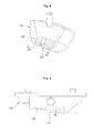
- FIG. 8 is a perspective view illustrating the inside of a washing machine in accordance with another embodiment of the present invention.
- FIG. 9 is a perspective view of a spray nozzle of a washing machine in accordance with another embodiment of the present invention.
- FIG. 1 is a perspective view illustrating the inside of the washing machine in accordance with the first embodiment of the present invention
- FIG. 2 is a longitudinal-sectional view of the washing machine of FIG. 1 .
- the washing machine of this embodiment includes an outer case 10 forming the external appearance of the washing machine, a tub 20 installed in the outer case 10 for containing washing water, and a drum 30 rotatably installed in the tub 20.
- the outer case 10 protects various components installed therein, and forms the external appearance of the washing machine.
- the tub 20 is supported in the outer case 10 by a spring 21 and dampers 22, and contains washing water supplied from the outside through a water supply device 50.
- the drum 30 for containing laundry is rotatably installed in the tub 20, and a driving unit 40 is installed on the rear end of the tub 20 and drives the drum 30.
- a plurality of dehydration holes 31, through which the washing water flows into and out of the drum 30, are formed through the circumferential surface of the drum 30.
- the washing water is supplied to the drum 30 through the dehydration holes 31, and in dehydration, the washing water contained in the laundry is discharged to the outside of the drum through the dehydration holes 31.
- a plurality of lifters 32 are protruded from the inner circumferential surface of the drum 30 in the lengthwise direction of the drum 30.
- the lifters 32 lift up the laundry contained in the drum 30 in the rotating direction of the drum 30.
- the laundry is elevated and dropped by the rotation of the drum 3 0, thereby being washed.
- a door 60 which can be opened and closed, is formed at the front surface of the drum 30 such that laundry can be put into and taken out of the drum 30 through the door 60.
- a gasket 70 which covers a gap between the front surface of the tub 20 and the rear surface of the door 60, such that the tub 20 containing the washing water forms a sealed space when the door 60 is closed, is formed in the circumferential direction.
- the gasket 70 is made of an elastic member so as to absorb the vibration of the tub 20, and has a curved shape.
- the washing machine of this embodiment further includes a circulation unit 80 for circulating the washing water stored in the tub 20 to the upper portion of the drum 30.
- the washing machine of this embodiment includes the circulation unit 80 so as to supply the washing water stored in the tub 20 to the drum 30, and thus in a situation where the amount of the washing water contained in the tub 20 is small, the washing or rinsing of the laundry can be performed using the washing water.
- the circulation unit 80 includes a circulation channel 81, which supplies the washing water stored in the tub 20 to the drum 30.
- a circulation channel 81 which supplies the washing water stored in the tub 20 to the drum 30.
- one end of the circulation channel 81 is installed at the lower end of the tub 20, and is extended upwardly along the outline of the tub 20.
- the circulation unit 80 further includes a circulation pump 82, which pumps up the washing water along the circulation channel 81.
- the other end of the circulation channel 81 for discharging the washing water is located at the front region of the upper portion of the drum 30. Specifically, the other end of the circulation channel 81 passes through the upper portion of the gasket 70 or the tub 20, and discharges the washing water to the front region of the drum 30. Further, a spray nozzle 100 for supplying the washing water is provided at the other end of the circulation channel 81, from which the washing water is discharged.
- the spray nozzle 100 is located at a position separated from the front surface of the drum 30 by a designated interval so as to prevent the drum 30 from colliding with the spray nozzle 100 due to the vibration of the drum 30 generated during rotation.
- the washing water stored in the tub 20 is supplied to the drum 30 along the circulation channel 81 by the circulation unit 80, the laundry in the drum 30 can be washed or rinsed with a small amount of the washing water. Further, even in a situation where the tub 20 contains a sufficient amount of the washing water, washing water is additionally supplied to the drum 30 from the upper part, and rapidly soaks laundry in the drum 30 when the laundry is put into the drum 30.
- the washing machine of this embodiment is operated in a penetration type washing method, in which the drum 30 is rotated at a high velocity by the driving unit 40 so as to wash or rinse the laundry in the drum 30.
- the penetration type washing method is where the laundry in the drum 30 is washed or rinsed by the rotation of the drum 30 at a high velocity such that the laundry is closely attached to the inner surface of the drum 30, differing from a general drum rotating velocity. At this time, the washing water contained in the laundry penetrates the laundry by the centrifugal force and is discharged to the outside of the drum 30, and thus the laundry is washed or rinsed.
- the drum 30 is rotated at a high velocity.
- the supplied washing water may maintain a level lower than the lower surface of the drum 30.
- the washing water is circulated upwardly by the circulation unit 80, and is continuously supplied to the inside of the drum 30. After the supplied washing water penetrates the laundry due to the high-velocity rotation of the drum 30, the washing water is discharged to the outside of the drum 30, and is stored in the bottom of the tub 20 along the inner wall of the tub 20.
- the spray nozzle 100 spraying the washing water circulated by the circulation unit 80 to the inside of the drum 30 is disposed so that the spray nozzle 100 sprays the washing water to the rear portion of the inside of the drum 30.
- the spray nozzle 100 will be described in detail with reference to FIGs. 3 to 5 .
- FIG. 3 is a schematic view illustrating the spray of washing water by the spray nozzle 100
- FIG. 4 is a perspective view of the spray nozzle 100
- FIG. 5 is a plan view of the spray nozzle 100.
- the drum 30 has a cylindrical shape provided with an opened front surface, and the spray nozzle 100 is installed at a position close to the front portion of the drum 30.
- the washing water may not be supplied to the laundry located at the rear portion of the inside of the drum 30.
- the spray nozzle 100 of this embodiment is preferably configured such that it can spray the washing water to the rear portion of the drum 30 as well as the front portion of the drum 30. That is, the spray nozzle 100 is configured such that it can spray the washing water in various directions, so as to supply the washing water uniformly to the laundry contained in the drum 30.
- the spray nozzle 100 preferably sprays the washing water uniformly to the drum 30 in the lengthwise direction of the lower end of the drum 30 so as to concentratively supply the washing water to the laundry even if the drum 30 is not rotated.
- the spray nozzle 100 includes a plurality of spray holes 110 turning toward the inside of the drum 30.
- the respective spray holes 110 spray the washing water onto different falling positions in the lengthwise direction of the drum 30.
- the respective spray holes 110 spray the washing water onto different positions of the lower region of the drum 30, separated at a designated interval from the front portion to the rear portion of the drum 30, thus uniformly dispersing the washing water in the lengthwise direction of the drum 30.
- the washing water is supplied uniformly to the laundry. Further, even in a situation where the drum 30 is not rotated and thus the laundry is concentrated on the lower portion of the drum 30, it is possible to supply the washing water to the laundry.
- the spray nozzle 100 may include a plurality of spray units, which are installed at different positions so as to branch off the washing water supplied by the circulation unit 80 into various directions (with reference to FIG. 8 ).
- a procedure of assembling the plurality of the spray units (100a, 100b, 100c, 100d) installed at different positions may be complicated.
- the spray nozzle 100 in this embodiment preferably includes a plurality of the spray holes 110 formed through a single case, as shown in FIG. 5 .
- the respective spray holes 110 preferably have different shapes or different channels.
- the spray nozzle 100 is located at the front portion of the drum 30 provided with an opening.
- the spray holes 110 preferably have different washing water spray directions or spray velocities.
- the respective spray holes 110 have different cross-sectional areas such that hydraulic pressures of the washing water sprayed through the spray holes 110 can be different.
- the washing water sprayed at a low hydraulic pressure is sprayed in a shape similar to that in natural falling, and the washing water sprayed at a high hydraulic pressure tends to proceed in the spraying direction rather than the shape of natural falling.
- the washing water sprayed at a low hydraulic pressure is supplied to the front portion of the drum 30 adjacent to the position of the spray nozzle 100, and the washing water sprayed at a high hydraulic pressure is supplied to the rear portion of the drum 30.
- velocity components of the washing water sprayed through the respective spray holes 100 may be different. Even if the washing water is sprayed through the same spray hole 100, the washing water may fall onto different positions according to the velocity component of the washing water.
- the spray nozzle 100 includes a plurality of channels 120, through which the washing water supplied from the circulation unit 80 passes, and the plurality of the channels 120 correspond to the plurality of the spray holes 110.
- the channels 120 have different shapes, and thus the washing water passed through the respective channels 120 are sprayed with different velocity components.
- the washing water passed through the channel 120 which is formed in the vertical direction, falls just onto the front portion of the drum 30, and the washing water passed through the channel 120, which is extended in the inward direction of the drum 30, has a velocity component in the inward direction of the drum 30 and thus can be sprayed onto the rear portion of the drum 30.
- the spray nozzle 100 is preferably configured such that the spray hole 110 connected to the longer length channel 120 extended in the inward direction of the drum 30 sprays the washing water to the more rear portion of the inside of the drum 30.
- the spray nozzle 100 in this embodiment employs the above-described principle.
- the spray nozzle 100 includes a plurality of the spray holes 110 having different cross-sectional areas, and the spray holes 110 are connected to the channels 120 having different shapes.
- the spray holes 110 disposed in the direction (a) spray the washing water at a high hydraulic pressure
- the spray holes 110 disposed in the direction (b) spray the washing water at a low hydraulic pressure.
- the channels 120 connected to the spray holes 110 disposed in the direction (a) are extended to a long length in the inward direction of the drum 30, and the channels 120 connected to the spray holes 110 disposed in the direction (b) are extended to a short length in the inward direction of the drum 30.
- the portion of the spray nozzle 110, on which the spray holes 120 are formed has a stepwise shape so as to differentiate the lengths of the channels 120 extended in the inward direction of the drum 30.
- the spray holes 110 disposed in the direction (a) spray the washing water having a high velocity component in the inward direction of the drum 30 at a high hydraulic pressure, and thus the washing water is supplied to the rear portion of the drum 30.
- the spray holes 110 spray the washing water having a lower velocity component in the inward direction of the drum 30 at a lower hydraulic pressure, and the washing water cannot reach the rear portion of the drum 30 and falls around the front portion of the drum 30.
- the spray nozzle 100 in this embodiment can spray washing water uniformly to the inside of the drum 30 from the front portion to the rear portion of the drum 30 in the lengthwise direction of the lower end of the drum 30.
- the spray nozzle 100 is installed at the front region of the upper portion of the drum 30. In a situation where one spray nozzle is installed, it is preferable that the spray nozzle is installed at the front region of the upper end of the drum 30.
- the spray nozzles are installed at positions being close to designated sides such that they can be installed at symmetrical positions centered on the upper end of the drum 30.
- FIG. 4 illustrates the spray nozzle 100, which is located at a position close to one side.
- this nozzle is preferably installed at a position close to the other side so as to be symmetrical with the spray nozzle 100 of FIG. 4 .
- the channels 120 connected to the respective spray holes 110 are formed in directions corresponding to positions at which the washing water from the spray holes 110 falls. That is, the spray nozzle 100 in this embodiment supplies the washing water in the lengthwise direction of the lower end of the drum 30. Thus, it is preferable that the channels 120 are formed towards the center of the drum 30.
- the surface of the spray nozzle 100, on which the spray holes 110 are formed is inclined at a designated angle with the opened front surface of the drum 30.
- the angles can be varied according to the position of the spray nozzle 100, and can be varied in a designated range according to the hydraulic pressure of the sprayed washing water or the angles of the channels 120.
- the first embodiment describes the washing machine which supplies washing water to the inside of the drum 30 in various directions using the spray nozzle 100 having a plurality of the spray holes 110.
- FIGs. 6 and 7 Some parts in this embodiment, which are substantially the same as those in the first embodiment, are denoted by the same reference numerals even though they are depicted in different drawings, and a detailed description thereof will thus be omitted because it is considered to be unnecessary.
- the first embodiment describes the washing machine, which supplies washing water to different positions using the spray nozzle 100 having a plurality of the spray holes 110
- the second embodiment describes a washing machine including a spray nozzle 100 having one spray hole 110.
- the spray nozzle 100 sprays washing water through one spray hole 110.
- the spray nozzle 100 has a channel 120, the width of which is gradually increased in the flowing direction of the washing water passing therethrough, such that the washing water passing through the spray nozzle 100 is dispersed in the width direction and is sprayed.
- This structure employs a phenomenon, in which when the end of a hose connected to a water supply is pressed flatly, water passing through the end is widely dispersed at a high hydraulic pressure. Thus, even though the washing water is supplied through one spray hole 110, the washing water can be supplied to the inside of the drum 30 in various directions.
- the channel 120 formed in the spray nozzle 100 preferably has a shape in which the height of the cross-section of the channel 120 is gradually decreased in the flowing direction of the washing water.
- the cross-sectional area of the channel 120 is gradually decreased.
- the spray hole 110 spraying the washing water has a slim and long shape so as to form the smallest cross-sectional area of the channel 120.
- the cross-sectional area of the channel 120 of the spray nozzle 100 is decreased in the flowing direction of the washing water, and thus the hydraulic pressure of the washing water sprayed from the spray nozzle 100 is increased.
- the washing water is easily dispersed in the width direction, and is supplied to the inside of the drum at a high hydraulic pressure.
- guide ribs 130 for inducing the dispersion of the washing water in the width direction are provided in the channel 120, through which the washing water passes.
- the guide ribs 130 are disposed in the width direction, and are inclined in the flowing direction of the washing water, thus inducing the uniform dispersion of the washing water in the width direction.
- FIG. 7 is a schematic view illustrating the spray of washing water by the spray nozzle 100 in accordance with this embodiment.
- the spray nozzle 100 in this embodiment is installed such that the spray hole 110 is parallel with the front surface of the drum 30, although the drum 30 is rotated, washing water may not be supplied to a designated position in the drum 30.
- the spray hole 110 of the spray nozzle 100 is inclined at a designated angle with the front surface of the drum 30.
- the spray nozzle 100 in this embodiment uniformly sprays washing water in the lengthwise direction of the lower end of the drum 30.
- the spray nozzle 100 is obliquely installed toward the drum 30 such that the washing water sprayed from one end of the spray hole 110 is supplied to the front portion of the lower end of the drum 30 and the washing water sprayed from the other end of the spray hole 110 is supplied to the rear portion of the lower end of the drum 30.
- this embodiment provides a washing machine which supplies washing water continuously from the front portion to the rear portion of the lower end of the drum 30.
- FIG. 9 a washing machine in accordance with a third embodiment of the present invention will be described with reference to FIG. 9 .
- Some parts in this embodiment which are substantially the same as those in the first and second embodiments, are denoted by the same reference numerals even though they are depicted in different drawings, and a detailed description thereof will thus be omitted because it is considered to be unnecessary.
- the first and second embodiments respectively describe the washing machines in which the spray directions of washing water are adjusted by the shape and position of the spray nozzle 100.
- the third embodiment describes a washing machine, in which the direction of washing water sprayed from a spray nozzle 100 is adjusted by a driving part 150, such as a motor. That is, in this embodiment, washing water is not sprayed in various directions concurrently, but the spray direction of the washing water continuously varies using the driving part 50.
- the spray nozzle 100 includes a body part 140, which sprays washing water, and the driving part 150, which adjusts the spray position of the washing water.
- Washing water circulated by the circulation unit 80 is supplied to the body part 140, and the body part 140 includes spray holes 110 which spray the washing water to the drum 30.
- the body part 140 is configured such that it can be fixed to the driving part 150 and vary the spray direction of the washing water by the control of the driving part 150.
- the driving part 150 is fixed to the inside of the tub 20 in front of the drum 30, and is provided with a driving device (not shown), such as a motor, therein.
- a driving device such as a motor
- the motor may be an electric motor powered by electricity, or a fluid motor powered by the flow of the washing water from the circulation unit 80.
- both sides of the body part 140 are respectively fixed to the driving part 150.
- the body part 140 is rotated at a designated angle on a shaft formed at both side surfaces, and sprays washing water in various directions.
- the falling position of the washing water sprayed by the body part 140 continuously varies, and preferably reciprocates from the front end to the rear end of the lower portion of the drum 30.
- the present invention is not limited thereto. Besides, the present invention may be applied to various machines including a laundry treating machine, in which a spray nozzle adjusts the spray direction of washing water using a driving device.
- washing water can be supplied to the inside of the drum in various directions by adjusting the hydraulic pressure of the spray nozzle spraying the washing water and the direction(s) of the channel(s), or using a driving device, such as a motor.
- the washing machine of the present invention reduces the amount of the washing water required to wash and rinse laundry to save water, and supplies the washing water uniformly to the laundry contained in the drum through the spray nozzle to enhance the laundry washing and rinsing effects.
Landscapes
- Engineering & Computer Science (AREA)
- Textile Engineering (AREA)
- Detail Structures Of Washing Machines And Dryers (AREA)
- Detergent Compositions (AREA)
- Main Body Construction Of Washing Machines And Laundry Dryers (AREA)
Applications Claiming Priority (1)
| Application Number | Priority Date | Filing Date | Title |
|---|---|---|---|
| KR1020080032618A KR20090107223A (ko) | 2008-04-08 | 2008-04-08 | 세탁장치 |
Publications (3)
| Publication Number | Publication Date |
|---|---|
| EP2108731A2 true EP2108731A2 (de) | 2009-10-14 |
| EP2108731A3 EP2108731A3 (de) | 2016-11-02 |
| EP2108731B1 EP2108731B1 (de) | 2018-03-28 |
Family
ID=40791685
Family Applications (1)
| Application Number | Title | Priority Date | Filing Date |
|---|---|---|---|
| EP09151022.2A Active EP2108731B1 (de) | 2008-04-08 | 2009-01-21 | Waschmaschine |
Country Status (10)
| Country | Link |
|---|---|
| US (1) | US20090249838A1 (de) |
| EP (1) | EP2108731B1 (de) |
| KR (1) | KR20090107223A (de) |
| CN (1) | CN101555655A (de) |
| AU (1) | AU2009234618A1 (de) |
| BR (1) | BRPI0909196B8 (de) |
| CA (1) | CA2720703A1 (de) |
| RU (1) | RU2463396C2 (de) |
| TR (1) | TR201806843T4 (de) |
| WO (1) | WO2009125917A2 (de) |
Cited By (7)
| Publication number | Priority date | Publication date | Assignee | Title |
|---|---|---|---|---|
| EP2602381A3 (de) * | 2011-12-07 | 2013-10-02 | Samsung Electronics Co., Ltd | Trommelwaschmaschine und Waschverfahren dafür |
| WO2014131450A1 (en) * | 2013-02-28 | 2014-09-04 | Arcelik Anonim Sirketi | Washing machine water jet nozzle |
| CN108796965A (zh) * | 2017-04-28 | 2018-11-13 | 青岛海尔洗衣机有限公司 | 一种洗衣机 |
| WO2020015982A1 (en) * | 2018-07-19 | 2020-01-23 | Arcelik Anonim Sirketi | An integrated spray head |
| US11408115B2 (en) | 2018-02-22 | 2022-08-09 | Electrolux Appliances Aktiebolag | Laundry washing machine equipped with a liquid supply line |
| EP4234798A3 (de) * | 2016-12-28 | 2023-10-18 | LG Electronics Inc. | Waschmaschine |
| EP4234797A3 (de) * | 2017-11-09 | 2023-10-18 | LG Electronics Inc. | Waschmaschine |
Families Citing this family (43)
| Publication number | Priority date | Publication date | Assignee | Title |
|---|---|---|---|---|
| US8763184B2 (en) * | 2008-08-01 | 2014-07-01 | Lg Electronics Inc. | Control method of a laundry machine |
| KR20100028920A (ko) * | 2008-09-05 | 2010-03-15 | 엘지전자 주식회사 | 세탁 방법 및 세탁기 |
| US20110030149A1 (en) * | 2008-08-01 | 2011-02-10 | In Ho Cho | Control method of a laundry machine |
| US8713736B2 (en) | 2008-08-01 | 2014-05-06 | Lg Electronics Inc. | Control method of a laundry machine |
| US9416478B2 (en) | 2009-03-31 | 2016-08-16 | Lg Electronics Inc. | Washing machine and washing method |
| US20100024137A1 (en) * | 2008-08-01 | 2010-02-04 | Myong Hum Im | Washing machine and washing method therefor |
| US8746015B2 (en) * | 2008-08-01 | 2014-06-10 | Lg Electronics Inc. | Laundry machine |
| US8966944B2 (en) | 2008-08-01 | 2015-03-03 | Lg Electronics Inc. | Control method of a laundry machine |
| US20110047716A1 (en) * | 2008-08-01 | 2011-03-03 | In Ho Cho | Control method of a laundry machine |
| WO2010093185A2 (ko) | 2009-02-11 | 2010-08-19 | 엘지전자 주식회사 | 세탁 방법 및 세탁기 |
| US9822473B2 (en) | 2009-07-27 | 2017-11-21 | Lg Electronics Inc. | Control method of a laundry machine |
| US9234307B2 (en) * | 2009-07-27 | 2016-01-12 | Lg Electronics Inc. | Control method of a laundry machine |
| US10533275B2 (en) | 2009-07-27 | 2020-01-14 | Lg Electronics Inc. | Control method of a laundry machine |
| US9695537B2 (en) | 2009-07-27 | 2017-07-04 | Lg Electronics Inc. | Control method of a laundry machine |
| KR101700187B1 (ko) * | 2009-10-21 | 2017-01-26 | 엘지전자 주식회사 | 세탁물 처리기기 및 세탁물 처리방법 |
| US8776297B2 (en) * | 2009-10-13 | 2014-07-15 | Lg Electronics Inc. | Laundry treating apparatus and method |
| US9045853B2 (en) * | 2009-10-13 | 2015-06-02 | Lg Electronics Inc. | Laundry treating apparatus |
| KR101608657B1 (ko) * | 2009-10-13 | 2016-04-04 | 엘지전자 주식회사 | 세탁물 처리기기 |
| JP5325861B2 (ja) * | 2010-09-28 | 2013-10-23 | 日立アプライアンス株式会社 | ドラム式洗濯乾燥機 |
| BR112013026143A2 (pt) * | 2011-04-14 | 2021-01-12 | Lg Electronics, Inc. | Método de lavagem |
| WO2013012247A2 (ko) | 2011-07-18 | 2013-01-24 | 엘지전자 주식회사 | 세탁기 및 세탁기의 세탁수 공급방법 |
| CN102828378B (zh) * | 2012-09-18 | 2017-11-24 | 姜伟 | 超低碳自适应滚筒洗衣机及其洗衣方法 |
| RU2517544C1 (ru) * | 2013-02-11 | 2014-05-27 | Федеральное государственное бюджетное образовательное учреждение высшего профессионального образования "Южно-Российский государственный университет экономики и сервиса" (ФГБОУ ВПО "ЮРГУЭС") | Стиральная машина барабанного типа со струйной обработкой изделий |
| JP2014200535A (ja) * | 2013-04-08 | 2014-10-27 | パナソニック株式会社 | 洗濯機 |
| KR101299507B1 (ko) * | 2013-04-16 | 2013-08-29 | 엘지전자 주식회사 | 세탁물 처리기기 |
| USD748356S1 (en) * | 2013-07-16 | 2016-01-26 | Whirlpool Corporation | Container for a clothes washing machine |
| USD761501S1 (en) | 2013-09-27 | 2016-07-12 | Whirlpool Corporation | Container for clothes washing machine |
| CN103556436B (zh) * | 2013-09-29 | 2015-11-25 | 江苏海狮机械集团有限公司 | 微粒洗衣机中滚筒的喷水装置 |
| KR102155003B1 (ko) * | 2013-10-24 | 2020-09-11 | 엘지전자 주식회사 | 세탁기 |
| KR102183472B1 (ko) * | 2013-11-07 | 2020-11-27 | 삼성전자주식회사 | 세탁기 |
| KR20150053608A (ko) * | 2013-11-08 | 2015-05-18 | 삼성전자주식회사 | 세탁기 |
| KR102378129B1 (ko) * | 2015-04-27 | 2022-03-24 | 엘지전자 주식회사 | 의류처리장치 |
| KR102512212B1 (ko) * | 2016-02-23 | 2023-03-22 | 삼성전자주식회사 | 세탁기 및 그 제어방법 |
| KR102573125B1 (ko) * | 2017-12-28 | 2023-08-30 | 엘지전자 주식회사 | 세탁기 |
| CN110042628A (zh) * | 2018-01-15 | 2019-07-23 | 青岛海尔滚筒洗衣机有限公司 | 衣物处理设备及其喷淋装置 |
| JP2021519192A (ja) * | 2018-04-16 | 2021-08-10 | チンタオ・ハイアール・ドラム・ウォッシング・マシーン・カンパニー・リミテッド | ドラム洗濯機及びそのスプレーシステム |
| CN110387698A (zh) * | 2018-04-16 | 2019-10-29 | 青岛海尔滚筒洗衣机有限公司 | 滚筒洗衣机及其喷淋系统 |
| CN110387699B (zh) * | 2018-04-16 | 2021-10-29 | 青岛海尔洗涤电器有限公司 | 滚筒洗衣机及其喷淋系统 |
| WO2019201118A1 (zh) * | 2018-04-16 | 2019-10-24 | 青岛海尔滚筒洗衣机有限公司 | 滚筒洗衣机及其喷淋系统 |
| CN110468558A (zh) * | 2018-05-10 | 2019-11-19 | 青岛海尔滚筒洗衣机有限公司 | 滚筒洗衣机及其喷淋系统和密封窗垫 |
| CN110552150B (zh) * | 2018-05-31 | 2022-09-23 | 无锡小天鹅电器有限公司 | 衣物处理装置的注水控制方法、装置和衣物处理装置 |
| CN110607661A (zh) * | 2018-06-15 | 2019-12-24 | 青岛海尔滚筒洗衣机有限公司 | 滚筒洗衣机和洗衣机的喷嘴 |
| US11174584B2 (en) * | 2019-01-10 | 2021-11-16 | Haier Us Appliance Solutions, Inc. | Integrated cap cleaner for a washing machine appliance |
Family Cites Families (34)
| Publication number | Priority date | Publication date | Assignee | Title |
|---|---|---|---|---|
| US1434625A (en) * | 1918-05-13 | 1922-11-07 | F C Austin Machinery Company | Combined flushing and sprinkling nozzle |
| US1335267A (en) * | 1919-05-02 | 1920-03-30 | Ambrose Jennings Grant | Sprinkler |
| US1457750A (en) * | 1921-03-21 | 1923-06-05 | Renner Frank Knoerle | Washing machine |
| US1958038A (en) * | 1930-11-14 | 1934-05-08 | Speakman Co | Shower bath spray head |
| US2343742A (en) * | 1939-11-21 | 1944-03-07 | Westinghouse Electric & Mfg Co | Washing apparatus |
| US2322559A (en) * | 1940-01-24 | 1943-06-22 | Westinghouse Electric & Mfg Co | Laundry apparatus |
| US2556303A (en) * | 1945-03-09 | 1951-06-12 | Traube Abraham | Rotary washing and drying machine |
| US2593357A (en) * | 1947-08-16 | 1952-04-15 | Spooner William Wycliffe | Nozzle for the ejection of fluid streams |
| US2625031A (en) * | 1948-07-02 | 1953-01-13 | Standard Telephones Cables Ltd | Washing machine provided with resilient collapsible inlet |
| US2778687A (en) * | 1954-10-11 | 1957-01-22 | Hanson Equipment Company | Spray nozzle |
| US2964248A (en) * | 1955-11-18 | 1960-12-13 | Spraying Systems Co | Plural orifice fan shaped spray nozzle |
| US3035777A (en) * | 1959-11-10 | 1962-05-22 | Robert L Bodell | Distribution system for agricultural liquids |
| US3387310A (en) * | 1966-09-22 | 1968-06-11 | Donald E. Marshall | Washing apparatus and method |
| US3388410A (en) * | 1967-09-11 | 1968-06-18 | Donald E. Marshall | Cleaning apparatus and method |
| DE2806873C3 (de) * | 1978-02-17 | 1981-03-26 | Bauknecht Hausgeräte GmbH, 70565 Stuttgart | Trommelwasch- und Trockenmaschine |
| US4303406A (en) * | 1980-03-14 | 1981-12-01 | The Maytag Company | Automatic liquid level control |
| US4733819A (en) * | 1981-06-01 | 1988-03-29 | Aghnides Elie P | Showerhead with means for selecting various forms of output streams |
| US4489574A (en) * | 1981-11-10 | 1984-12-25 | The Procter & Gamble Company | Apparatus for highly efficient laundering of textiles |
| SU1669632A1 (ru) * | 1988-04-07 | 1991-08-15 | Всесоюзный научно-исследовательский и проектно-конструкторский институт металлургического машиностроения им.А.И.Целикова | Форсунка дл вторичного охлаждени непрерывнолитого слитка |
| RU2002872C1 (ru) * | 1991-07-30 | 1993-11-15 | Малое государственное предпри тие "Аквамаш" | Стирально-отжимна машина |
| US5199127A (en) * | 1992-01-02 | 1993-04-06 | Whirlpool Corporation | Method for rinsing fabric articles in a vertical axis washer |
| DE4310594A1 (de) * | 1993-03-31 | 1994-10-06 | Bosch Siemens Hausgeraete | Waschmaschine mit einer innerhalb eines Laugenbehälters waagerecht gelagerten, mantelbeschickbaren Wäschetrommel |
| US6015099A (en) * | 1993-12-10 | 2000-01-18 | Potomac Rain Room, Inc. | Method and apparatus for spraying pressurized water |
| MY115384A (en) * | 1994-12-06 | 2003-05-31 | Sharp Kk | Drum type washing machine and drier |
| US5823018A (en) * | 1995-12-18 | 1998-10-20 | Daewoo Electronics Co., Ltd. | Washing machine having a spraying nozzle assembly |
| US5690282A (en) * | 1996-04-10 | 1997-11-25 | Guo; Wen-Li | Spray nozzle device |
| JP3436644B2 (ja) * | 1996-10-30 | 2003-08-11 | シャープ株式会社 | ドラム式洗濯機 |
| US6691536B2 (en) * | 2000-06-05 | 2004-02-17 | The Procter & Gamble Company | Washing apparatus |
| DE10227958A1 (de) * | 2002-06-22 | 2004-01-08 | Electrolux Home Products Corporation N.V. | Waschmaschine |
| KR100493306B1 (ko) * | 2002-12-11 | 2005-06-07 | 엘지전자 주식회사 | 드럼세탁기 |
| KR100688160B1 (ko) * | 2003-08-07 | 2007-03-02 | 엘지전자 주식회사 | 프론트 로딩 타입 드럼 세탁기 |
| DE602004029123D1 (de) * | 2003-08-13 | 2010-10-28 | Lg Electronics Inc | Waschmaschine mit Dampferzeuger und Wasserzirkulation |
| KR20050061774A (ko) * | 2003-12-18 | 2005-06-23 | 엘지전자 주식회사 | 드럼 세탁기의 세탁수 순환장치 |
| KR100767685B1 (ko) * | 2006-03-30 | 2007-10-17 | 엘지전자 주식회사 | 탑 로딩 드럼 세탁기 |
-
2008
- 2008-04-08 KR KR1020080032618A patent/KR20090107223A/ko not_active Application Discontinuation
- 2008-11-20 US US12/275,000 patent/US20090249838A1/en not_active Abandoned
-
2009
- 2009-01-14 AU AU2009234618A patent/AU2009234618A1/en not_active Abandoned
- 2009-01-14 RU RU2010145126/12A patent/RU2463396C2/ru active
- 2009-01-14 CA CA2720703A patent/CA2720703A1/en not_active Abandoned
- 2009-01-14 BR BRPI0909196A patent/BRPI0909196B8/pt active IP Right Grant
- 2009-01-14 WO PCT/KR2009/000187 patent/WO2009125917A2/en active Application Filing
- 2009-01-21 EP EP09151022.2A patent/EP2108731B1/de active Active
- 2009-01-21 TR TR2018/06843T patent/TR201806843T4/tr unknown
- 2009-04-08 CN CNA200910131881XA patent/CN101555655A/zh active Pending
Cited By (11)
| Publication number | Priority date | Publication date | Assignee | Title |
|---|---|---|---|---|
| EP2602381A3 (de) * | 2011-12-07 | 2013-10-02 | Samsung Electronics Co., Ltd | Trommelwaschmaschine und Waschverfahren dafür |
| US9222210B2 (en) | 2011-12-07 | 2015-12-29 | Samsung Electronics Co., Ltd. | Drum washing machine and washing method thereof |
| WO2014131450A1 (en) * | 2013-02-28 | 2014-09-04 | Arcelik Anonim Sirketi | Washing machine water jet nozzle |
| EP4234798A3 (de) * | 2016-12-28 | 2023-10-18 | LG Electronics Inc. | Waschmaschine |
| US11920278B2 (en) | 2016-12-28 | 2024-03-05 | Lg Electronics Inc. | Washing machine |
| CN108796965A (zh) * | 2017-04-28 | 2018-11-13 | 青岛海尔洗衣机有限公司 | 一种洗衣机 |
| EP4234797A3 (de) * | 2017-11-09 | 2023-10-18 | LG Electronics Inc. | Waschmaschine |
| US11866879B2 (en) | 2017-11-09 | 2024-01-09 | Lg Electronics Inc. | Laundry treating apparatus having a nozzle |
| US11920283B2 (en) | 2017-11-09 | 2024-03-05 | Lg Electronics Inc. | Washing machine having circulation nozzles |
| US11408115B2 (en) | 2018-02-22 | 2022-08-09 | Electrolux Appliances Aktiebolag | Laundry washing machine equipped with a liquid supply line |
| WO2020015982A1 (en) * | 2018-07-19 | 2020-01-23 | Arcelik Anonim Sirketi | An integrated spray head |
Also Published As
| Publication number | Publication date |
|---|---|
| BRPI0909196A2 (pt) | 2017-01-10 |
| CA2720703A1 (en) | 2009-10-15 |
| BRPI0909196B8 (pt) | 2019-07-02 |
| RU2463396C2 (ru) | 2012-10-10 |
| WO2009125917A3 (en) | 2010-12-02 |
| EP2108731B1 (de) | 2018-03-28 |
| CN101555655A (zh) | 2009-10-14 |
| RU2010145126A (ru) | 2012-05-20 |
| AU2009234618A1 (en) | 2009-10-15 |
| EP2108731A3 (de) | 2016-11-02 |
| US20090249838A1 (en) | 2009-10-08 |
| KR20090107223A (ko) | 2009-10-13 |
| BRPI0909196B1 (pt) | 2019-05-14 |
| TR201806843T4 (tr) | 2018-06-21 |
| WO2009125917A2 (en) | 2009-10-15 |
Similar Documents
| Publication | Publication Date | Title |
|---|---|---|
| EP2108731B1 (de) | Waschmaschine | |
| US9045853B2 (en) | Laundry treating apparatus | |
| KR102314314B1 (ko) | 의류처리장치 | |
| EP2271800B1 (de) | Waschmaschine | |
| US9249534B2 (en) | Laundry treating apparatus and method | |
| KR101820662B1 (ko) | 드럼세탁기 및 드럼세탁기의 세탁방법 | |
| JP5749736B2 (ja) | 洗濯方法及び洗濯機 | |
| KR100688160B1 (ko) | 프론트 로딩 타입 드럼 세탁기 | |
| US9273424B2 (en) | Washing machine | |
| KR102378129B1 (ko) | 의류처리장치 | |
| JP2006110362A (ja) | 洗濯機 | |
| KR101602671B1 (ko) | 세탁물 처리기기 | |
| US20170101734A1 (en) | Laundry treating apparatus | |
| KR20100106260A (ko) | 세탁기 | |
| KR20060033588A (ko) | 세탁기 | |
| KR100696423B1 (ko) | 스팀 발생장치를 구비하는 드럼세탁기 | |
| KR20100110716A (ko) | 세탁물 처리기기 | |
| KR19980041940A (ko) | 세탁기 | |
| KR101325766B1 (ko) | 세탁물 처리기기 | |
| KR20220021862A (ko) | 의류처리장치 및 이의 제어방법 | |
| KR20220021708A (ko) | 의류처리장치 | |
| KR20130045314A (ko) | 세탁물 처리기기 | |
| KR20060033589A (ko) | 세탁기 | |
| KR20050121051A (ko) | 세탁기 |
Legal Events
| Date | Code | Title | Description |
|---|---|---|---|
| PUAI | Public reference made under article 153(3) epc to a published international application that has entered the european phase |
Free format text: ORIGINAL CODE: 0009012 |
|
| 17P | Request for examination filed |
Effective date: 20090218 |
|
| AK | Designated contracting states |
Kind code of ref document: A2 Designated state(s): AT BE BG CH CY CZ DE DK EE ES FI FR GB GR HR HU IE IS IT LI LT LU LV MC MK MT NL NO PL PT RO SE SI SK TR |
|
| AX | Request for extension of the european patent |
Extension state: AL BA RS |
|
| PUAL | Search report despatched |
Free format text: ORIGINAL CODE: 0009013 |
|
| AK | Designated contracting states |
Kind code of ref document: A3 Designated state(s): AT BE BG CH CY CZ DE DK EE ES FI FR GB GR HR HU IE IS IT LI LT LU LV MC MK MT NL NO PL PT RO SE SI SK TR |
|
| AX | Request for extension of the european patent |
Extension state: AL BA RS |
|
| RIC1 | Information provided on ipc code assigned before grant |
Ipc: D06F 39/08 20060101AFI20160928BHEP |
|
| RBV | Designated contracting states (corrected) |
Designated state(s): AT BE BG CH CY CZ DE DK EE ES FI FR GB GR HR HU IE IS IT LI LT LU LV MC MK MT NL NO PL PT RO SE SI SK TR |
|
| RBV | Designated contracting states (corrected) |
Designated state(s): AT BE BG CH CY CZ DE DK EE ES FI FR GB GR HR HU IE IS IT LI LT LU LV MC MK MT NL NO PL PT RO SE SI SK TR |
|
| AKX | Designation fees paid |
Designated state(s): AT BE BG CH CY CZ DE DK EE ES FI FR GB GR HR HU IE IS IT LI LT LU LV MC MK MT NL NO PL PT RO SE SI SK TR |
|
| AXX | Extension fees paid |
Extension state: BA Extension state: RS Extension state: AL |
|
| GRAP | Despatch of communication of intention to grant a patent |
Free format text: ORIGINAL CODE: EPIDOSNIGR1 |
|
| STAA | Information on the status of an ep patent application or granted ep patent |
Free format text: STATUS: GRANT OF PATENT IS INTENDED |
|
| INTG | Intention to grant announced |
Effective date: 20171107 |
|
| GRAJ | Information related to disapproval of communication of intention to grant by the applicant or resumption of examination proceedings by the epo deleted |
Free format text: ORIGINAL CODE: EPIDOSDIGR1 |
|
| STAA | Information on the status of an ep patent application or granted ep patent |
Free format text: STATUS: REQUEST FOR EXAMINATION WAS MADE |
|
| GRAR | Information related to intention to grant a patent recorded |
Free format text: ORIGINAL CODE: EPIDOSNIGR71 |
|
| GRAS | Grant fee paid |
Free format text: ORIGINAL CODE: EPIDOSNIGR3 |
|
| INTC | Intention to grant announced (deleted) | ||
| STAA | Information on the status of an ep patent application or granted ep patent |
Free format text: STATUS: GRANT OF PATENT IS INTENDED |
|
| GRAA | (expected) grant |
Free format text: ORIGINAL CODE: 0009210 |
|
| STAA | Information on the status of an ep patent application or granted ep patent |
Free format text: STATUS: THE PATENT HAS BEEN GRANTED |
|
| AK | Designated contracting states |
Kind code of ref document: B1 Designated state(s): AT BE BG CH CY CZ DE DK EE ES FI FR GB GR HR HU IE IS IT LI LT LU LV MC MK MT NL NO PL PT RO SE SI SK TR |
|
| INTG | Intention to grant announced |
Effective date: 20180220 |
|
| REG | Reference to a national code |
Ref country code: GB Ref legal event code: FG4D |
|
| REG | Reference to a national code |
Ref country code: CH Ref legal event code: EP |
|
| REG | Reference to a national code |
Ref country code: AT Ref legal event code: REF Ref document number: 983540 Country of ref document: AT Kind code of ref document: T Effective date: 20180415 |
|
| REG | Reference to a national code |
Ref country code: IE Ref legal event code: FG4D |
|
| REG | Reference to a national code |
Ref country code: DE Ref legal event code: R096 Ref document number: 602009051453 Country of ref document: DE |
|
| PG25 | Lapsed in a contracting state [announced via postgrant information from national office to epo] |
Ref country code: FI Free format text: LAPSE BECAUSE OF FAILURE TO SUBMIT A TRANSLATION OF THE DESCRIPTION OR TO PAY THE FEE WITHIN THE PRESCRIBED TIME-LIMIT Effective date: 20180328 Ref country code: NO Free format text: LAPSE BECAUSE OF FAILURE TO SUBMIT A TRANSLATION OF THE DESCRIPTION OR TO PAY THE FEE WITHIN THE PRESCRIBED TIME-LIMIT Effective date: 20180628 Ref country code: HR Free format text: LAPSE BECAUSE OF FAILURE TO SUBMIT A TRANSLATION OF THE DESCRIPTION OR TO PAY THE FEE WITHIN THE PRESCRIBED TIME-LIMIT Effective date: 20180328 Ref country code: LT Free format text: LAPSE BECAUSE OF FAILURE TO SUBMIT A TRANSLATION OF THE DESCRIPTION OR TO PAY THE FEE WITHIN THE PRESCRIBED TIME-LIMIT Effective date: 20180328 |
|
| REG | Reference to a national code |
Ref country code: NL Ref legal event code: MP Effective date: 20180328 |
|
| REG | Reference to a national code |
Ref country code: LT Ref legal event code: MG4D |
|
| PG25 | Lapsed in a contracting state [announced via postgrant information from national office to epo] |
Ref country code: BG Free format text: LAPSE BECAUSE OF FAILURE TO SUBMIT A TRANSLATION OF THE DESCRIPTION OR TO PAY THE FEE WITHIN THE PRESCRIBED TIME-LIMIT Effective date: 20180628 Ref country code: GR Free format text: LAPSE BECAUSE OF FAILURE TO SUBMIT A TRANSLATION OF THE DESCRIPTION OR TO PAY THE FEE WITHIN THE PRESCRIBED TIME-LIMIT Effective date: 20180629 Ref country code: SE Free format text: LAPSE BECAUSE OF FAILURE TO SUBMIT A TRANSLATION OF THE DESCRIPTION OR TO PAY THE FEE WITHIN THE PRESCRIBED TIME-LIMIT Effective date: 20180328 Ref country code: LV Free format text: LAPSE BECAUSE OF FAILURE TO SUBMIT A TRANSLATION OF THE DESCRIPTION OR TO PAY THE FEE WITHIN THE PRESCRIBED TIME-LIMIT Effective date: 20180328 |
|
| PG25 | Lapsed in a contracting state [announced via postgrant information from national office to epo] |
Ref country code: EE Free format text: LAPSE BECAUSE OF FAILURE TO SUBMIT A TRANSLATION OF THE DESCRIPTION OR TO PAY THE FEE WITHIN THE PRESCRIBED TIME-LIMIT Effective date: 20180328 Ref country code: PL Free format text: LAPSE BECAUSE OF FAILURE TO SUBMIT A TRANSLATION OF THE DESCRIPTION OR TO PAY THE FEE WITHIN THE PRESCRIBED TIME-LIMIT Effective date: 20180328 Ref country code: RO Free format text: LAPSE BECAUSE OF FAILURE TO SUBMIT A TRANSLATION OF THE DESCRIPTION OR TO PAY THE FEE WITHIN THE PRESCRIBED TIME-LIMIT Effective date: 20180328 Ref country code: NL Free format text: LAPSE BECAUSE OF FAILURE TO SUBMIT A TRANSLATION OF THE DESCRIPTION OR TO PAY THE FEE WITHIN THE PRESCRIBED TIME-LIMIT Effective date: 20180328 Ref country code: ES Free format text: LAPSE BECAUSE OF FAILURE TO SUBMIT A TRANSLATION OF THE DESCRIPTION OR TO PAY THE FEE WITHIN THE PRESCRIBED TIME-LIMIT Effective date: 20180328 |
|
| PG25 | Lapsed in a contracting state [announced via postgrant information from national office to epo] |
Ref country code: CZ Free format text: LAPSE BECAUSE OF FAILURE TO SUBMIT A TRANSLATION OF THE DESCRIPTION OR TO PAY THE FEE WITHIN THE PRESCRIBED TIME-LIMIT Effective date: 20180328 Ref country code: SK Free format text: LAPSE BECAUSE OF FAILURE TO SUBMIT A TRANSLATION OF THE DESCRIPTION OR TO PAY THE FEE WITHIN THE PRESCRIBED TIME-LIMIT Effective date: 20180328 |
|
| REG | Reference to a national code |
Ref country code: AT Ref legal event code: MK05 Ref document number: 983540 Country of ref document: AT Kind code of ref document: T Effective date: 20180328 |
|
| PG25 | Lapsed in a contracting state [announced via postgrant information from national office to epo] |
Ref country code: PT Free format text: LAPSE BECAUSE OF FAILURE TO SUBMIT A TRANSLATION OF THE DESCRIPTION OR TO PAY THE FEE WITHIN THE PRESCRIBED TIME-LIMIT Effective date: 20180730 |
|
| REG | Reference to a national code |
Ref country code: DE Ref legal event code: R097 Ref document number: 602009051453 Country of ref document: DE |
|
| PG25 | Lapsed in a contracting state [announced via postgrant information from national office to epo] |
Ref country code: AT Free format text: LAPSE BECAUSE OF FAILURE TO SUBMIT A TRANSLATION OF THE DESCRIPTION OR TO PAY THE FEE WITHIN THE PRESCRIBED TIME-LIMIT Effective date: 20180328 Ref country code: DK Free format text: LAPSE BECAUSE OF FAILURE TO SUBMIT A TRANSLATION OF THE DESCRIPTION OR TO PAY THE FEE WITHIN THE PRESCRIBED TIME-LIMIT Effective date: 20180328 |
|
| PLBE | No opposition filed within time limit |
Free format text: ORIGINAL CODE: 0009261 |
|
| STAA | Information on the status of an ep patent application or granted ep patent |
Free format text: STATUS: NO OPPOSITION FILED WITHIN TIME LIMIT |
|
| 26N | No opposition filed |
Effective date: 20190103 |
|
| PG25 | Lapsed in a contracting state [announced via postgrant information from national office to epo] |
Ref country code: SI Free format text: LAPSE BECAUSE OF FAILURE TO SUBMIT A TRANSLATION OF THE DESCRIPTION OR TO PAY THE FEE WITHIN THE PRESCRIBED TIME-LIMIT Effective date: 20180328 |
|
| PG25 | Lapsed in a contracting state [announced via postgrant information from national office to epo] |
Ref country code: MC Free format text: LAPSE BECAUSE OF FAILURE TO SUBMIT A TRANSLATION OF THE DESCRIPTION OR TO PAY THE FEE WITHIN THE PRESCRIBED TIME-LIMIT Effective date: 20180328 |
|
| REG | Reference to a national code |
Ref country code: CH Ref legal event code: PL |
|
| PG25 | Lapsed in a contracting state [announced via postgrant information from national office to epo] |
Ref country code: LU Free format text: LAPSE BECAUSE OF NON-PAYMENT OF DUE FEES Effective date: 20190121 |
|
| REG | Reference to a national code |
Ref country code: BE Ref legal event code: MM Effective date: 20190131 |
|
| REG | Reference to a national code |
Ref country code: IE Ref legal event code: MM4A |
|
| PG25 | Lapsed in a contracting state [announced via postgrant information from national office to epo] |
Ref country code: BE Free format text: LAPSE BECAUSE OF NON-PAYMENT OF DUE FEES Effective date: 20190131 |
|
| PG25 | Lapsed in a contracting state [announced via postgrant information from national office to epo] |
Ref country code: CH Free format text: LAPSE BECAUSE OF NON-PAYMENT OF DUE FEES Effective date: 20190131 Ref country code: LI Free format text: LAPSE BECAUSE OF NON-PAYMENT OF DUE FEES Effective date: 20190131 |
|
| PG25 | Lapsed in a contracting state [announced via postgrant information from national office to epo] |
Ref country code: IE Free format text: LAPSE BECAUSE OF NON-PAYMENT OF DUE FEES Effective date: 20190121 |
|
| PG25 | Lapsed in a contracting state [announced via postgrant information from national office to epo] |
Ref country code: MT Free format text: LAPSE BECAUSE OF NON-PAYMENT OF DUE FEES Effective date: 20190121 |
|
| PG25 | Lapsed in a contracting state [announced via postgrant information from national office to epo] |
Ref country code: CY Free format text: LAPSE BECAUSE OF FAILURE TO SUBMIT A TRANSLATION OF THE DESCRIPTION OR TO PAY THE FEE WITHIN THE PRESCRIBED TIME-LIMIT Effective date: 20180328 |
|
| PG25 | Lapsed in a contracting state [announced via postgrant information from national office to epo] |
Ref country code: IS Free format text: LAPSE BECAUSE OF FAILURE TO SUBMIT A TRANSLATION OF THE DESCRIPTION OR TO PAY THE FEE WITHIN THE PRESCRIBED TIME-LIMIT Effective date: 20180728 |
|
| PG25 | Lapsed in a contracting state [announced via postgrant information from national office to epo] |
Ref country code: HU Free format text: LAPSE BECAUSE OF FAILURE TO SUBMIT A TRANSLATION OF THE DESCRIPTION OR TO PAY THE FEE WITHIN THE PRESCRIBED TIME-LIMIT; INVALID AB INITIO Effective date: 20090121 |
|
| PG25 | Lapsed in a contracting state [announced via postgrant information from national office to epo] |
Ref country code: MK Free format text: LAPSE BECAUSE OF FAILURE TO SUBMIT A TRANSLATION OF THE DESCRIPTION OR TO PAY THE FEE WITHIN THE PRESCRIBED TIME-LIMIT Effective date: 20180328 |
|
| PGFP | Annual fee paid to national office [announced via postgrant information from national office to epo] |
Ref country code: GB Payment date: 20221205 Year of fee payment: 15 Ref country code: FR Payment date: 20221205 Year of fee payment: 15 |
|
| PGFP | Annual fee paid to national office [announced via postgrant information from national office to epo] |
Ref country code: IT Payment date: 20221206 Year of fee payment: 15 |
|
| P01 | Opt-out of the competence of the unified patent court (upc) registered |
Effective date: 20230610 |
|
| PGFP | Annual fee paid to national office [announced via postgrant information from national office to epo] |
Ref country code: DE Payment date: 20231205 Year of fee payment: 16 |