EP2107872B1 - Vorrichtung und verfahren zur herstellung einer fondantmasse - Google Patents
Vorrichtung und verfahren zur herstellung einer fondantmasse Download PDFInfo
- Publication number
- EP2107872B1 EP2107872B1 EP07858025A EP07858025A EP2107872B1 EP 2107872 B1 EP2107872 B1 EP 2107872B1 EP 07858025 A EP07858025 A EP 07858025A EP 07858025 A EP07858025 A EP 07858025A EP 2107872 B1 EP2107872 B1 EP 2107872B1
- Authority
- EP
- European Patent Office
- Prior art keywords
- fondant
- mixer
- ultrasound
- starting solution
- mass
- Prior art date
- Legal status (The legal status is an assumption and is not a legal conclusion. Google has not performed a legal analysis and makes no representation as to the accuracy of the status listed.)
- Not-in-force
Links
- 238000004519 manufacturing process Methods 0.000 title claims abstract description 10
- 238000000034 method Methods 0.000 title claims abstract description 9
- 239000000203 mixture Substances 0.000 title abstract description 8
- 238000002604 ultrasonography Methods 0.000 claims abstract description 28
- 238000002425 crystallisation Methods 0.000 claims abstract description 22
- 230000008025 crystallization Effects 0.000 claims abstract description 22
- 238000001816 cooling Methods 0.000 claims description 26
- 238000002156 mixing Methods 0.000 claims description 19
- 230000003068 static effect Effects 0.000 claims description 7
- 239000000126 substance Substances 0.000 claims description 5
- 238000011144 upstream manufacturing Methods 0.000 claims description 2
- 230000001960 triggered effect Effects 0.000 claims 1
- 239000013078 crystal Substances 0.000 description 22
- XLYOFNOQVPJJNP-UHFFFAOYSA-N water Substances O XLYOFNOQVPJJNP-UHFFFAOYSA-N 0.000 description 6
- 239000000654 additive Substances 0.000 description 4
- 230000015572 biosynthetic process Effects 0.000 description 4
- 235000009508 confectionery Nutrition 0.000 description 4
- 239000002826 coolant Substances 0.000 description 4
- 239000008103 glucose Substances 0.000 description 4
- 238000001704 evaporation Methods 0.000 description 3
- WQZGKKKJIJFFOK-GASJEMHNSA-N Glucose Natural products OC[C@H]1OC(O)[C@H](O)[C@@H](O)[C@@H]1O WQZGKKKJIJFFOK-GASJEMHNSA-N 0.000 description 2
- 238000010276 construction Methods 0.000 description 2
- 239000000110 cooling liquid Substances 0.000 description 2
- 238000001953 recrystallisation Methods 0.000 description 2
- 230000001105 regulatory effect Effects 0.000 description 2
- 230000000996 additive effect Effects 0.000 description 1
- 235000015173 baked goods and baking mixes Nutrition 0.000 description 1
- 230000001055 chewing effect Effects 0.000 description 1
- 230000001419 dependent effect Effects 0.000 description 1
- 238000011161 development Methods 0.000 description 1
- 230000018109 developmental process Effects 0.000 description 1
- 238000009826 distribution Methods 0.000 description 1
- 239000000975 dye Substances 0.000 description 1
- 230000000694 effects Effects 0.000 description 1
- 230000008020 evaporation Effects 0.000 description 1
- 230000005284 excitation Effects 0.000 description 1
- 230000010006 flight Effects 0.000 description 1
- 125000002791 glucosyl group Chemical group C1([C@H](O)[C@@H](O)[C@H](O)[C@H](O1)CO)* 0.000 description 1
- 238000009776 industrial production Methods 0.000 description 1
- 238000010008 shearing Methods 0.000 description 1
- 238000000527 sonication Methods 0.000 description 1
- 235000021092 sugar substitutes Nutrition 0.000 description 1
- 239000003765 sweetening agent Substances 0.000 description 1
- 238000005496 tempering Methods 0.000 description 1
- 238000009827 uniform distribution Methods 0.000 description 1
Images


Classifications
-
- A—HUMAN NECESSITIES
- A23—FOODS OR FOODSTUFFS; TREATMENT THEREOF, NOT COVERED BY OTHER CLASSES
- A23G—COCOA; COCOA PRODUCTS, e.g. CHOCOLATE; SUBSTITUTES FOR COCOA OR COCOA PRODUCTS; CONFECTIONERY; CHEWING GUM; ICE-CREAM; PREPARATION THEREOF
- A23G3/00—Sweetmeats; Confectionery; Marzipan; Coated or filled products
- A23G3/0002—Processes of manufacture not relating to composition and compounding ingredients
- A23G3/0057—Fondant beating or creaming
-
- A—HUMAN NECESSITIES
- A23—FOODS OR FOODSTUFFS; TREATMENT THEREOF, NOT COVERED BY OTHER CLASSES
- A23G—COCOA; COCOA PRODUCTS, e.g. CHOCOLATE; SUBSTITUTES FOR COCOA OR COCOA PRODUCTS; CONFECTIONERY; CHEWING GUM; ICE-CREAM; PREPARATION THEREOF
- A23G3/00—Sweetmeats; Confectionery; Marzipan; Coated or filled products
- A23G3/0002—Processes of manufacture not relating to composition and compounding ingredients
- A23G3/0004—Processes specially adapted for manufacture or treatment of sweetmeats or confectionery
- A23G3/0006—Manufacture or treatment of liquids, pastes, creams, granules, shred or powder
-
- A—HUMAN NECESSITIES
- A23—FOODS OR FOODSTUFFS; TREATMENT THEREOF, NOT COVERED BY OTHER CLASSES
- A23G—COCOA; COCOA PRODUCTS, e.g. CHOCOLATE; SUBSTITUTES FOR COCOA OR COCOA PRODUCTS; CONFECTIONERY; CHEWING GUM; ICE-CREAM; PREPARATION THEREOF
- A23G3/00—Sweetmeats; Confectionery; Marzipan; Coated or filled products
- A23G3/02—Apparatus specially adapted for manufacture or treatment of sweetmeats or confectionery; Accessories therefor
- A23G3/14—Fondant beating or creaming machines
Definitions
- the present invention relates to an apparatus and a method for producing a fondant composition, which is used in particular for the production of confectionery.
- a supersaturated sugar-glucose solution with a high sugar content is usually used. This solution is then cooled by gentle tempering to a region of greater supersaturation and then subjected to a mechanical action with a tabling screw or a paddle mixer with further cooling targeted shear. This triggers a recrystallization process in the fondant mass. Subsequently, a further processing to a desired confectionery takes place.
- a machine for the industrial production of fondant masses thus comprises a relatively large mechanical mixing area.
- the inventive device for producing a fondant mass with the features of claim 1 has the advantage that it has a significantly simple and inexpensive construction. Furthermore, a change in the amount and size of the crystals in the fudge mass can be adjusted in a targeted manner.
- the device comprises an ultrasonic device which ultrasound in a line section, in which a Fondantausgangsown is promoted, to initiate a crystallization in the Fondantausgangshut to produce the crystalline fondant mass. Due to imploding bubbles, the ultrasound introduced into the fondant output solution generates local pressure changes, at which crystallization nuclei form and thus trigger the crystallization in the fondant starting solution.
- the shape and size of the crystals formed can be changed by regulating the amplitude of the ultrasound. As a result, different crystal forms and different crystal sizes can be produced.
- so-called “seed crystals" are generated, where the crystallization continues.
- the ultrasonic device comprises a sonotrode, which is arranged in the fondant output solution.
- the sonotrode protrudes into the Fondantausgangshack and is washed by this.
- a targeted introduction of the ultrasound to form nuclei can be carried out.
- the device comprises a cooling device.
- the cooling device is preferably arranged in the flow direction of the fondant output solution upstream of the ultrasound device and / or in the region of the ultrasound device and / or after the ultrasound device.
- the cooling device has in particular the task to dissipate the heat resulting from the crystallization again from the mass.
- the cooling is thus particularly preferably by means of water.
- the cooling device further preferably comprises a double-walled tube, wherein the mass is conveyed in the interior of the tube and a cooling liquid is supplied between the two walls of the double-walled tube.
- the cooling liquid can be guided in the flow direction of the mass or against the flow direction of the mass.
- the ultrasonic device is arranged in a T-shaped pipe section.
- a particularly compact and simple construction can be provided.
- the discharge area of the device comprises a mixing area with a vacuum.
- a vacuum means a negative pressure which is significantly below the ambient pressure.
- the vacuum is preferably generated by means of a suction device.
- the apparatus further comprises a mixer, which is arranged downstream of the ultrasonic device in the flow direction of the fondant output solution in order to mix the mass in which the crystallization nuclei are located and to maintain the crystallization in a controlled manner.
- the mixer is preferably a dynamic mixer, such as a rotating screw or rotating paddle, or preferably a static mixer, such as e.g. fixed baffles in a tube.
- the cooling device is additionally arranged in the region of the mixer or in the region of the mixer, a second cooling device is arranged. In this way, it can be ensured in particular that a further cooling of the mass takes place at the mixer.
- the present invention further relates to a process for producing a fondant composition, wherein a crystallization of the fondant composition is initiated by means of ultrasound.
- a fondant starting solution is sonicated, whereby crystallization nuclei are formed in the fondant starting solution due to cavitation effects by imploding bubbles, at which a crystallization of the fondant starting solution can propagate.
- the method can be controlled in particular by regulating the amplitude of the ultrasound and the duration of the application of ultrasound so that as far as possible a fondant mass is produced in which at least 90% of the crystals have a crystal size of less than 20 microns. As a result, a very homogeneous and small-crystalline fondant mass can be provided.
- the method further comprises the step of mixing the fondant starting solution after the introduction of the ultrasound.
- the nuclei generated by the ultrasound can be defined in a defined manner by mixing, for example by means of mechanical, driven mixers or by means of static mixers, e.g. fixed baffles in the pipe to be generated in a defined manner.
- the ultrasound is introduced into the fondant starting solution continuously or at predetermined intervals. This also allows the size and type of crystals to be controlled.
- FIG. 1 shows in particular the part of a machine in which the crystallization is carried out.
- a sugar solution 7 is prepared as a fondant starting solution in a first step, which is essentially a supersaturated sugar-glucose solution with a high sugar content.
- One end of the line 12 opens into a T-piece 14, in which an ultrasonic device 4 is arranged.
- a sonotrode 4a of the ultrasound device 4 projects into the flowing sugar solution 7 (cf. FIG. 1 ).
- the ultrasonic device 4 comprises a generator 4b and a sonotrode 4a.
- the generator generates the ultrasonic power, which is then introduced via the sonotrode 4a in the continuously flowing sugar mass flow.
- a region which lies in front of the ultrasonic device 4 in the flow direction is referred to as a supply region 2, and a region which is arranged downstream of the ultrasound device 4 is referred to as discharge region 3.
- the device 1 further comprises a cooling device 5, which has the task of cooling the crystallizing sugar solution 7.
- the cooling device 5 comprises a first cooling pipe 5a, which is arranged in the region of the T-piece 14, and a second cooling pipe 5b, which is arranged in the discharge region 3.
- the first cooling pipe 5a is connected to the second cooling pipe 5b via a connecting pipe 5c.
- the two cooling tubes 5a, 5b are provided as double-walled tubes, in the interior of which the sugar solution 7 flows and a coolant, such as water, is guided between the two walls in the double-walled tube.
- a flow direction of the coolant is the same as a flow direction of the sugar solution 7.
- the inflow of the coolant into the cooling device 5 is indicated by the arrow D and an outflow of the coolant is indicated by the arrow E.
- the device I further comprises a mixer 6, which is arranged downstream of the ultrasound device 4 in the direction of flow of the sugar solution.
- the mixer 6 is in this embodiment, a static mixer, which by arranging stationary baffles 6a is provided inside the tube. How out FIG. 1 it can be seen, a plurality of baffles 6a are arranged in the interior of the tube, where there is a deflection of the crystallizing sugar solution.
- the function of the device 1 according to the invention is as follows:
- the sugar solution 7 is conducted past the ultrasound device 4 via the line 12.
- Ultrasound is applied to the supersaturated sugar solution 7 by the sonotrode 4a so that local pressure changes in the sugar solution 7 occur due to imploding bubbles. These imploding bubbles lead to the formation of nuclei, where the crystallization of the sugar solution continues to propagate.
- the heat released due to the crystallization is dissipated directly in the area of the ultrasound device 4 by the cooling device 5 for the most part.
- the static mixer 6 which redirects the sugar solution with the crystals formed therein and thus continues the crystallization in a defined manner.
- the heat generated by the further crystallization is likewise removed by the cooling device.
- a fondant mass 9 is formed, which has a desired crystal size and thus a corresponding fondant quality.
- the size of the crystals can be adjusted in this case, in particular, by a change in the amplitude of the ultrasound or by a change in a duration of the sonication.
- the fondant mass 9 is then, as indicated by the arrow B, used for further processing for the production of confectionery.
- one or more additives such as dyes or flavorings, can be supplied via a line 10 which is arranged in front of the static mixer 6. Since this happens before the mixer 6, it is ensured that a sufficient mixing of the additives with the sugar solution 7 occurs. This results in a uniform distribution of the additives in the fondant mass.
- a temperature of the crystallized fondant mass 9 at the outlet is preferably between 55 ° C and 60 ° C, but may also be up to 70 ° C.
- the feed temperature of the supersaturated sugar solution 7 is preferably about 55 ° C.
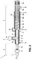
- FIG. 2 a device 1 according to a second embodiment of the invention described. Identical or functionally identical parts are denoted by the same reference numerals as in the first embodiment.
- FIG. 2 in contrast to the first embodiment in the second embodiment, the discharge region 3 is formed differently.
- the dynamic mixer 16 includes a shaft 16a, on which a plurality of mixing paddle 16b are arranged. It should be noted that instead of mixing paddles, for example, mixing sticks or the like. can be provided.
- the mixing paddles 16b ensure intensive mixing of the mass.
- a screw device 17 is provided on the shaft 16a of the dynamic mixer at the beginning of the mixing section.
- the screw means 17 may comprise one or more flights and ensures a secure forced conveying of the mass.
- the shaft 16a of the dynamic mixer 16 is ground by means of a drive 16c, for example an electric motor. Furthermore, fixed paddles 16d are arranged on the housing edge of the mixing section. Thus, the crystallization started at the ultrasonic device 4 is continued by the dynamic mixer 16.
- FIG. 3 a device 1 according to a third embodiment of the invention described in detail. Identical or functionally identical parts are again denoted by the same reference numerals as in the preceding embodiments.
- the device 1 for producing a fondant mass 9 in turn comprises a supply region 2 and a discharge region 3.
- the supply region 2 is arranged at an angle of 90 ° to the discharge region 3.
- a Ultrasonic device 4 provided with a projecting into the flowing sugar solution 7 Sonotrode 4a.
- a pinch valve 18 is provided for metering the sugar solution 7.
- a dynamic mixer 16 comprising a shaft 16 a, a plurality of mixer paddles 16 b and a drive 16 c and a cooling device 5, respectively.
- the dynamic mixer 16 is arranged in a mixer chamber 20 in which a vacuum 21 is applied. This is done by means of a suction device 22. By applying the vacuum results in a decrease in temperature, so that a re-evaporation of water contained in the mass occurs. These water vapors are removed by means of the suction device 22, so that the mass in the region of the dynamic mixer 16 has a greater supersaturation. As a result, the crystal formation is enhanced, so that by supporting the dynamic mixer 16, the crystals are further distributed and the excitation of additional crystals is enhanced.
- the cooling device 5 also provides in this embodiment for the removal of the heat introduced by the shear by means of the mixer paddle 16b and the crystal formation. Due to the additional evaporation of water by means of the vacuum 21, in the third embodiment, the temperature in the feed region 2 of the supersaturated sugar solution 7 can also be 100 ° C. or more.
- a pump 23 is provided to withdraw the finished-crystallized fudge mass 9 from the mixing area.
- the term "sugar” or “glucose” also means sugar substitutes or glucose exchange substances.
- the produced fondant composition can be used in particular for the production of Fondantg screenagen, products with Formauf spallungen, Fondantüberpp for bakery products and as an additive for Toffee personality or chewing candy.
Landscapes
- Life Sciences & Earth Sciences (AREA)
- Chemical & Material Sciences (AREA)
- Engineering & Computer Science (AREA)
- Food Science & Technology (AREA)
- Polymers & Plastics (AREA)
- Confectionery (AREA)
- Organic Low-Molecular-Weight Compounds And Preparation Thereof (AREA)
Description
- Die vorliegende Erfindung betrifft eine Vorrichtung und ein Verfahren zur Herstellung einer Fondantmasse, welche insbesondere zur Herstellung von Süßwaren verwendet wird.
- Zur Herstellung einer Fondantmasse wird üblicherweise eine übersättigte Zucker-Glukose-Lösung mit einem hohen Zuckeranteil verwendet. Diese Lösung wird dann durch schonende Temperierung auf einen Bereich stärkerer Übersättigung abgekühlt und dann durch einen mechanischen Vorgang mit einer Tablierschnecke oder einem Paddelmischer unter weiterer Kühlung gezielt einer Scherung ausgesetzt. Hierdurch wird ein Rekristallisationsprozess in der Fondantmasse ausgelöst. Anschließend erfolgt eine weitere Verarbeitung zu einer gewünschten Süßware. Um eine ausreichende Kristallisation der Fondantmasse zu erreichen, umfasst somit eine Maschine zur industriellen Herstellung von Fondantmassen einen relativ großen mechanischen Mischbereich. Insbesondere sind große und lange Kühlschnecken mit anschließenden Tablierschnecken oder große Paddelmischer notwendig, um durch Scherung die Rekristallisation in der Fondantmasse anzustoßen und die entstandenen Kristalle zu verteilen. Hierbei müssen bis zu drei Schnecken mit einer Gesamtlänge von über 3 m nacheinander in Reihe geschaltet werden, um ein Produkt hoher Qualität mit möglichst gleichmäßiger Kristallverteilung und kleiner Kristallgröße herzustellen. Ferner bieten die bekannten Anlagen keine Möglichkeit, eine genaue Einstellung von Menge und Größe der Zuckerkristalle vorzunehmen. Für eine hohe Qualität der Fondantmasse sollte jedoch eine möglichst kleine Kristallgröße derart erreicht werden, dass ca. 90 % der Kristalle eine Größe von kleiner als 20 µm erreichen.
- Aus der
DE-1923636 ist eine Vorrichtung zur Herstellung von Fondantmasse bekannt, bei welcher am Ausgang eine Ultraschallvorrichtung vorgesehen ist, um die Fondantreigung zu Verbessern. - Die erfindungsgemäße Vorrichtung zur Herstellung einer Fondantmasse mit den Merkmalen des Patentanspruchs 1 weist demgegenüber den Vorteil auf, dass sie einen signifikant einfachen und kostengünstigen Aufbau aufweist. Ferner kann gezielt eine Änderung von Menge und Größe der Kristalle in der Fondantmasse eingestellt werden. Dies wird erfindungsgemäß dadurch erreicht, dass die Vorrichtung eine Ultraschalleinrichtung umfasst, welche Ultraschall in einen Leitungsabschnitt, in welchen eine Fondantausgangslösung gefördert wird, einbringt, um eine Kristallisation in der Fondantausgangslösung anzustoßen, um die kristalline Fondantmasse herzustellen. Der in die Fondantausgangslösung eingebrachte Ultraschall erzeugt aufgrund von implodierenden Bläschen lokale Druckänderungen, an denen sich Kristallisationskeime bilden und somit die Kristallisation in der Fondantausgangslösung anstoßen. Die Form und Größe der entstehenden Kristalle kann dabei durch eine Regelung der Amplitude des Ultraschalls verändert werden. Dadurch können unterschiedliche Kristallformen und unterschiedliche Kristallgrößen hergestellt werden. Durch das Einbringen von Ultraschall werden sogenannte "Impfkristalle" erzeugt, an denen sich die Kristallisation fortsetzt.
- Die Unteransprüche zeigen bevorzugte Weiterbildungen der Erfindung.
- Vorzugsweise umfasst die Ultraschalleinrichtung eine Sonotrode, welche in der Fondantausgangslösung angeordnet ist. Somit ragt die Sonotrode in die Fondantausgangslösung und wird von dieser umspült. Dadurch kann eine gezielte Einbringung des Ultraschalls zur Bildung von Kristallisationskeimen ausgeführt werden.
- Weiter bevorzugt umfasst die Vorrichtung eine Kühlvorrichtung. Die Kühlvorrichtung ist vorzugsweise in Strömungsrichtung der Fondantausgangslösung vor der Ultraschalleinrichtung und/oder im Bereich der Ultraschalleinrichtung und/oder nach der Ultraschalleinrichtung angeordnet. Die Kühleinrichtung hat insbesondere die Aufgabe, die aufgrund der Kristallisation entstehende Wärme wieder aus der Masse abzuführen. Die Kühlung erfolgt damit besonders bevorzugt mittels Wasser. Hierzu umfasst die Kühleinrichtung weiter bevorzugt ein doppelwandiges Rohr, wobei im Inneren des Rohrs die Masse gefördert wird und zwischen den beiden Wänden des doppelwandigen Rohrs eine Kühlflüssigkeit zugeführt wird. Die Kühlflüssigkeit kann dabei in Strömungsrichtung der Masse oder gegen die Strömungsrichtung der Masse geführt werden.
- Besonders bevorzugt ist die Ultraschalleinrichtung in einem T-förmigen Rohrstück angeordnet. Hierdurch kann ein besonders kompakter und einfacher Aufbau bereitgestellt werden.
- Weiter bevorzugt umfasst der Abfuhrbereich der Vorrichtung einen Mischbereich mit einem Vakuum. Hierdurch kann ein zusätzlicher Entzug von Wasser aus der Masse durch eine Nachverdampfung erfolgen, so dass es in diesem Bereich zu einer stärkeren Übersättigung der Masse kommt. Dadurch wird die Kristallbildung in der Masse verstärkt. Erfindungsgemäß wird hierbei unter dem Begriff "Vakuum" ein Unterdruck verstanden, welcher signifikant unterhalb des Umgebungsdrucks liegt. Das Vakuum wird vorzugsweise mittels einer Saugeinrichtung erzeugt.
- Gemäß einer weiteren bevorzugten Ausgestaltung der Erfindung umfasst die Vorrichtung ferner einen Mischer, welcher in Strömungsrichtung der Fondantausgangslösung nach der Ultraschalleinrichtung angeordnet ist, um die Masse, in welche die Kristallisationskeime befindlich sind, zu durchmischen und die Kristallisation weiter kontrolliert aufrecht zu erhalten. Der Mischer ist vorzugsweise ein dynamischer Mischer, wie beispielsweise eine rotierende Schnecke oder rotierende Paddel, oder vorzugsweise ein statischer Mischer, wie z.B. feststehende Leitbleche in einem Rohr.
- Weiter bevorzugt ist die Kühleinrichtung zusätzlich auch im Bereich des Mischers angeordnet oder im Bereich des Mischers ist eine zweite Kühleinrichtung angeordnet. Hierdurch kann insbesondere sichergestellt werden, dass eine weitere Abkühlung der Masse am Mischer erfolgt.
- Die vorliegende Erfindung betrifft ferner ein Verfahren zur Herstellung einer Fondantmasse, wobei eine Kristallisation der Fondantmasse mittels Ultraschall eingeleitet wird. Erfindungsgemäß wird hierbei eine Fondantausgangslösung mit Ultraschall beschallt, wodurch in der Fondantausgangslösung aufgrund von Kavitationseffekten durch implodierende Bläschen Kristallisationskeime entstehen, an denen eine Kristallisation der Fondantausgangslösung sich fortpflanzen kann. Durch die Verwendung des Ultraschalls kann das Verfahren insbesondere durch eine Regelung der Amplitude des Ultraschalls und der Zeitdauer des Anwendens von Ultraschall gesteuert werden, so dass möglichst eine Fondantmasse hergestellt wird, bei der mindestens 90 % der Kristalle eine Kristallgröße von kleiner als 20 µm aufweisen. Dadurch kann eine sehr homogene und kleinkristalline Fondantmasse bereitgestellt werden.
- Vorzugsweise umfasst das Verfahren ferner den Schritt des Durchmischens der Fondantausgangslösung nach dem Einbringen des Ultraschalls. Dadurch können die durch den Ultraschall erzeugten Kristallkeime in definierter Weise durch die Durchmischung, beispielsweise mittels mechanischer, angetriebener Mischer oder mittels statischer Mischer, z.B. feststehende Leitbleche im Rohr, in definierter Weise erzeugt werden.
- Weiter bevorzugt wird der Ultraschall kontinuierlich oder in vorbestimmten Intervallen in die Fondantausgangslösung eingebracht. Auch hierdurch kann die Größe und Art der Kristalle gesteuert werden.
- Nachfolgend werden bevorzugte Ausführungsbeispiele der Erfindung unter Bezugnahme auf die begleitende Zeichnung im Detail beschrieben. In der Zeichnung ist:
- Figur 1
- eine schematische Schnittansicht einer Vorrichtung zur Herstellung einer Fondantmasse gemäß einem ersten Ausführungsbeispiel der Erfindung,
- Figur 2
- eine schematische Schnittansicht einer Vorrichtung zur Herstellung von Fondantmassen gemäß einem zweiten Ausführungsbeispiel der Erfindung, und
- Figur 3
- eine schematische Schnittansicht einer Vorrichtung zur Herstellung von Fondantmassen gemäß einem dritten Ausführungsbeispiel der Erfindung.
- Nachfolgend wird unter Bezugnahme auf
Figur 1 eine Vorrichtung 1 zur Herstellung einer Fondantmasse 9 im Detail beschrieben.Figur 1 zeigt hierbei insbesondere den Teil einer Maschine, in welchem die Kristallisation durchgeführt wird. Für die Fondantmasse wird in einem ersten Schritt eine Zuckerlösung 7 als Fondantausgangslösung hergestellt, welche im Wesentlichen eine übersättigten Zucker-Glukose-Lösung mit hohem Zuckeranteil ist. Diese Zuckerlösung 7 wird, wie durch den Pfeil A inFigur 1 angedeutet, mittels einer Pumpe 11 in eine Leitung 12 gefördert. Ein Ende der Leitung 12 mündet in einem T-Stück 14, in welchem eine Ultraschalleinrichtung 4 angeordnet ist. Eine Sonotrode 4a der Ultraschalleinrichtung 4 ragt dabei in die strömende Zuckerlösung 7 (vgl.Figur 1 ). Durch die T-förmige Ausbildung der Leitung kann die Sonotrode 4a einfach in die strömende Zuckerlösung 7 integriert werden. Die Ultraschalleinrichtung 4 umfasst einen Generator 4b und eine Sonotrode 4a. Der Generator erzeugt die Ultraschallleistung, welche dann über die Sonotrode 4a in den kontinuierlich strömenden Zuckermassenstrom eingebracht wird. Ein Bereich, welcher in Strömungsrichtung vor der Ultraschalleinrichtung 4 liegt, wird als Zufuhrbereich 2 bezeichnet und ein Bereich, welcher in Strömungsrichtung nach der Ultraschalleinrichtung 4 angeordnet ist, wird als Abfuhrbereich 3 bezeichnet. - Die Vorrichtung 1 umfasst ferner eine Kühleinrichtung 5, welche die Aufgabe hat, die kristallisierende Zuckerlösung 7 zu kühlen. Wie aus
Figur 1 ersichtlich ist, umfasst die Kühleinrichtung 5 ein erstes Kühlrohr 5a, welches im Bereich des T-Stücks 14 angeordnet ist, und ein zweites Kühlrohr 5b, welches im Abfuhrbereich 3 angeordnet ist. Das erste Kühlrohr 5a ist über eine Verbindungsleitung 5c mit dem zweiten Kühlrohr 5b verbunden. In diesem Ausführungsbeispiel sind die beiden Kühlrohre 5a, 5b als doppelwandige Rohre vorgesehen, in deren Innerem die Zuckerlösung 7 strömt und ein Kühlmittel, wie z.B. Wasser, zwischen den beiden Wänden im doppelwandigen Rohr geführt wird. Eine Strömungsrichtung des Kühlmittels ist dabei gleich wie eine Strömungsrichtung der Zuckerlösung 7. Das Zuströmen des Kühlmittels in die Kühleinrichtung 5 wird durch den Pfeil D angedeutet und ein Abströmen des Kühlmittels wird durch den Pfeil E angedeutet. - Die Vorrichtung I umfasst ferner einen Mischer 6, welcher in Strömungsrichtung der Zuckerlösung nach der Ultraschalleinrichtung 4 angeordnet ist. Der Mischer 6 ist in diesem Ausführungsbeispiel ein statischer Mischer, welcher durch Anordnen von feststehenden Leitblechen 6a im Inneren des Rohres bereitgestellt wird. Wie aus
Figur 1 ersichtlich ist, sind hierbei eine Vielzahl von Leitblechen 6a im Inneren des Rohres angeordnet, an denen eine Umlenkung der kristallisierenden Zuckerlösung erfolgt. - Die Funktion der erfindungsgemäßen Vorrichtung 1 ist dabei wie folgt: Die Zuckerlösung 7 wird über die Leitung 12 an der Ultraschalleinrichtung 4 vorbeigeführt. Durch die Sonotrode 4a wird Ultraschall auf die übersättigte Zuckerlösung 7 aufgebracht, so dass durch implodierende Bläschen lokale Druckänderungen in der Zuckerlösung 7 auftreten. Diese implodierenden Bläschen führen zur Bildung von Kristallisationskeimen, an denen sich die Kristallisation der Zuckerlösung weiter fortpflanzt. Die aufgrund der Kristallisation frei werdende Wärme wird dabei unmittelbar im Bereich der Ultraschalleinrichtung 4 durch die Kühleinrichtung 5 größtenteils wieder abgeführt. Wie in
Figur 1 schematisch angedeutet, verstärkt sich die Kristallbildung in Strömungsrichtung nach der Ultraschalleinrichtung 4. Dies wird zusätzlich noch durch den statischen Mischer 6 unterstützt, welcher die Zuckerlösung mit den darin gebildeten Kristallen umlenkt und so die Kristallisation in definierter Weise weiterführt. Im Bereich des statischen Mischers wird die durch die weitergehende Kristallisation entstehende Wärme ebenfalls durch die Kühleinrichtung abgeführt. Nach dem Ende des Mischers 6 ist dann eine Fondantmasse 9 entstanden, welche eine gewünschte Kristallgröße und somit eine entsprechende Fondantqualität aufweist. Die Größe der Kristalle kann hierbei insbesondere durch eine Änderung der Amplitude des Ultraschalls oder durch eine Änderung einer Zeitdauer der Beschallung eingestellt werden. Die Fondantmasse 9 wird dann, wie durch den Pfeil B angedeutet, zur Weiterverarbeitung für eine Herstellung von Süßwaren verwendet. Falls gewünscht, kann über eine Leitung 10, welche vor dem statischen Mischer 6 angeordnet ist, noch einer oder mehrere Zusätze, z.B. Farbstoffe oder Geschmacksstoffe, zugeführt werden. Da dies vor dem Mischer 6 geschieht, ist sichergestellt, dass eine ausreichende Durchmischung der Zusätze mit der Zuckerlösung 7 auftritt. Dadurch erfolgt eine gleichmäßige Verteilung der Zusätze in der Fondantmasse 9. - Eine Temperatur der kristallisierten Fondantmasse 9 am Austritt liegt vorzugsweise zwischen 55°C und 60°C, kann evtl. jedoch auch bis 70°C betragen. Die Zufuhrtemperatur der übersättigten Zuckerlösung 7 beträgt vorzugsweise ca. 55°C.
- Nachfolgend wird unter Bezugnahme auf
Figur 2 eine Vorrichtung 1 gemäß einem zweiten Ausführungsbeispiel der Erfindung beschrieben. Gleiche bzw. funktional gleiche Teile sind mit den gleichen Bezugszeichen wie im ersten Ausführungsbeispiel bezeichnet. - Wie aus
Figur 2 ersichtlich ist, ist im Unterschied zum ersten Ausführungsbeispiel beim zweite Ausführungsbeispiel der Abfuhrbereich 3 unterschiedlich ausgebildet. Beim zweiten Ausführungsbeispiel ist kein Mischer in Form von in der Leitung fixierten Leitblechen vorgesehen, sondern eine Durchmischung erfolgt mittels eines dynamischen Mischers 16. Der dynamische Mischer 16 umfasst eine Welle 16a, auf welcher eine Vielzahl von Mischpaddel 16b angeordnet sind. Es sei angemerkt, dass anstelle der Mischpaddel auch z.B. Mischstifte o.Ä. vorgesehen sein können. Die Mischpaddel 16b sorgen für eine intensive Durchmischung der Masse. Ferner ist auf der Welle 16a des dynamischen Mischers zu Beginn der Mischstrecke noch eine Schneckeneinrichtung 17 vorgesehen. Die Schneckeneinrichtung 17 kann einen oder mehrere Schneckengänge umfassen und gewährleistet ein sicheres Zwangsfördern der Masse. Die Welle 16a des dynamischen Mischers 16 wird mittels eines Antriebs 16c, z.B. ein Elektromotor, angerieben. Ferner sind am Gehäuserand der Mischstrecke noch feststehende Paddel 16d angeordnet. Somit wird die an der Ultraschalleinrichtung 4 begonnene Kristallisation durch den dynamischen Mischer 16 fortgeführt. - Ansonsten entspricht dieses Ausführungsbeispiel dem vorhergehenden Ausführungsbeispiel, so dass auf die dort gegebene Beschreibung verwiesen werden kann.
- Nachfolgend wird unter Bezugnahme auf
Figur 3 eine Vorrichtung 1 gemäß einem dritten Ausführungsbeispiel der Erfindung im Detail beschrieben. Gleiche bzw. funktional gleiche Teile sind wieder mit den gleichen Bezugszeichen wie in den vorhergehenden Ausführungsbeispielen bezeichnet. - Wie aus
Figur 3 ersichtlich ist, umfasst die Vorrichtung 1 zur Herstellung einer Fondantmasse 9 wiederum einen Zufuhrbereich 2 und einen Abfuhrbereich 3. In diesem Ausführungsbeispiel ist jedoch der Zufuhrbereich 2 in einem Winkel von 90° zum Abfuhrbereich 3 angeordnet. Zum Anstoßen der Kristallisation ist wieder eine Ultraschalleinrichtung 4 mit einer in die strömende Zuckerlösung 7 ragenden Sonotrode 4a vorgesehen. In Strömungsrichtung der Zuckerlösung 7 vor der Ultraschalleinrichtung 4 ist ein Quetschventil 18 für eine Zumessung der Zuckerlösung 7 vorgesehen. Im Abfuhrbereich 3 ist ähnlich wie im zweiten Ausführungsbeispiel ein dynamischer Mischer 16, umfassend eine Welle 16a, eine Vielzahl von Mischerpaddel 16b und ein Antrieb 16c sowie eine Kühleinrichtung 5, angeordnet. - Im Unterschied zum zweiten Ausführungsbeispiel sind jedoch bei diesem Ausführungsbeispiel am Rand des Mischungsbereichs keine feststehenden Mischerpaddel vorgesehen. Zusätzlich können jedoch feststehende Mischelemente im Mischbereich vorgesehen werden. Der dynamische Mischer 16 ist in einem Mischerraum 20 angeordnet, in welchem ein Vakuum 21 angelegt wird. Dies erfolgt mittels einer Saugeinrichtung 22. Durch das Anlegen des Vakuums ergibt sich eine Temperaturabsenkung, so dass eine Nachverdampfung von in der Masse enthaltenen Wassers auftritt. Diese Wasserdämpfe werden mittels der Saugeinrichtung 22 abgeführt, so dass die Masse im Bereich des dynamischen Mischers 16 eine stärkere Übersättigung aufweist. Hierdurch wird die Kristallbildung verstärkt, so dass durch Unterstützung des dynamischen Mischers 16 die Kristalle weiter verteilt werden und die Anregung zusätzlicher Kristalle verstärkt wird. Die Kühleinrichtung 5 sorgt in diesem Ausführungsbeispiel ebenfalls für das Abführen der durch die Scherung mittels der Mischerpaddel 16b und die Kristallbildung eingebrachten Wärme. Durch das zusätzliche Ausdampfen von Wasser mittels des Vakuums 21 kann beim dritten Ausführungsbeispiel die Temperatur im Zufuhrbereich 2 der übersättigten Zuckerlösung 7 auch 100°C oder mehr betragen.
- Ferner ist eine Pumpe 23 vorgesehen, um die fertigkristallierte Fondantmasse 9 aus dem Mischbereich abzuziehen.
- Ansonsten entspricht dieses Ausführungsbeispiel den vorhergehenden Ausführungsbeispielen, so dass auf die dort gegebene Beschreibung verwiesen werden kann.
- Mit der in den drei Ausführungsbeispielen beschriebenen Vorrichtung 1 zur Herstellung einer Fondantmasse kann somit eine gezielte Kristallisation der Zuckerlösung 7 erreicht werden. Es sei angemerkt, dass erfindungsgemäß unter dem Begriff "Zucker" bzw. "Glukose" auch Zuckeraustauschstoffe bzw. Glukoseaustauschstoffe verstanden werden. Die hergestellte Fondantmasse kann insbesondere zur Herstellung von Fondantgießprodukten, Produkten mit Formauffüllungen, Fondantüberzüge für Backwarenartikel sowie als Zusatz für Toffeeartikel oder Kaubonbonartikel verwendet werden.
Claims (12)
- Vorrichtung zur Herstellung einer Fondantmasse (9), umfassend einen Zufuhrbereich (2) zur Zuführung einer Fondantausgangslösung (7), eine Ultraschalleinrichtung (4), welche Ultraschall in die Fondantausgangslösung (7) zuführt, um eine Kristallisation in der Fondantausgangslösung anzustoßen, und einen Abfuhrbereich (3), um die kristallisierte Fondantmasse (9) abzuführen.
- Vorrichtung nach Anspruch 1, dadurch gekennzeichnet, dass die Ultraschalleinrichtung (4) eine Sonotrode (4a) umfasst, welche in der Fondantausgangslösung (7) angeordnet ist.
- Vorrichtung nach einem der vorhergehenden Ansprüche, ferner umfassend eine Kühlvorrichtung (5; 15).
- Vorrichtung nach Anspruch 3, dadurch gekennzeichnet, dass die Kühleinrichtung (5; 15) in Strömungsrichtung der Fondantausgangslösung vor der Ultraschalleinrichtung (4) und/oder an der Ultraschalleinrichtung (4) und/oder nach der Ultraschalleinrichtung (4) angeordnet ist.
- Vorrichtung nach einem der vorhergehenden Ansprüche, dadurch gekennzeichnet, dass die Ultraschalleinrichtung (4) in einem T-förmigen Rohrstück (14) angeordnet ist.
- Vorrichtung nach einem der vorhergehenden Ansprüche, dadurch gekennzeichnet, dass der Abfuhrbereich (3) einen Mischbereich (20) mit einem Vakuum (21) umfasst.
- Vorrichtung nach einem der vorhergehenden Ansprüche, dadurch gekennzeichnet, dass der Abfuhrbereich (3) einen Mischer (6) umfasst.
- Vorrichtung nach Anspruch 7, dadurch gekennzeichnet, dass der Mischer ein dynamischer Mischer oder ein statischer Mischer ist.
- Vorrichtung nach einem der Ansprüche 3 bis 8, dadurch gekennzeichnet, dass die Kühleinrichtung (5; 15) auch im Bereich des Mischers angeordnet ist.
- Verfahren zur Herstellung einer Fondantmasse (9) aus einer Fondantausgangslösung (7), dadurch gekennzeichnet, dass eine Kristallisation der Fondantausgangslösung (7) mittels Ultraschall eingeleitet wird.
- Verfahren nach Anspruch 10, dadurch gekennzeichnet, dass die durch den Ultraschall angestoßene teilkristallisierte Fondantausgangslösung (7) durch Mischen zu einer kristallisierten Fondantmasse (9) wird.
- Verfahren nach Anspruch 10 oder 11, dadurch gekennzeichnet, dass Ultraschall kontinuierlich oder in Intervallen mit konstanter oder veränderter Amplitude in die Fondantausgangslösung (7) eingebracht wird.
Applications Claiming Priority (2)
| Application Number | Priority Date | Filing Date | Title |
|---|---|---|---|
| DE102007001292A DE102007001292A1 (de) | 2007-01-08 | 2007-01-08 | Vorrichtung und Verfahren zur Herstellung einer Fondantmasse |
| PCT/EP2007/064407 WO2008083911A1 (de) | 2007-01-08 | 2007-12-21 | Vorrichtung und verfahren zur herstellung einer fondantmasse |
Publications (2)
| Publication Number | Publication Date |
|---|---|
| EP2107872A1 EP2107872A1 (de) | 2009-10-14 |
| EP2107872B1 true EP2107872B1 (de) | 2010-03-24 |
Family
ID=39217921
Family Applications (1)
| Application Number | Title | Priority Date | Filing Date |
|---|---|---|---|
| EP07858025A Not-in-force EP2107872B1 (de) | 2007-01-08 | 2007-12-21 | Vorrichtung und verfahren zur herstellung einer fondantmasse |
Country Status (5)
| Country | Link |
|---|---|
| EP (1) | EP2107872B1 (de) |
| AT (1) | ATE461629T1 (de) |
| DE (2) | DE102007001292A1 (de) |
| ES (1) | ES2341814T3 (de) |
| WO (1) | WO2008083911A1 (de) |
Families Citing this family (1)
| Publication number | Priority date | Publication date | Assignee | Title |
|---|---|---|---|---|
| DE102016008296B4 (de) * | 2016-07-05 | 2020-02-20 | Technische Universität Bergakademie Freiberg | Verfahren und Vorrichtung zur Sonokristallisation |
Family Cites Families (5)
| Publication number | Priority date | Publication date | Assignee | Title |
|---|---|---|---|---|
| DE1923636A1 (de) * | 1969-05-09 | 1970-11-26 | Haensel Otto Gmbh | Verfahren und Vorrichtung zum kontinuierlichen Herstellen von Fondantmasse |
| DE3229937A1 (de) * | 1982-08-12 | 1984-02-16 | Reinhard 4401 Altenberge Brandt | Verfahren zur optimierung der erstarrungseigenschaften von fettmassen |
| WO1992020420A1 (en) * | 1991-05-03 | 1992-11-26 | Elizabeth Acton | Method and apparatus for the control of solidification in liquids |
| DE10137017A1 (de) * | 2001-07-30 | 2003-02-20 | Basf Ag | Kristallisationsverfahren zur Einstellung kleiner Partikel |
| DE10243837A1 (de) * | 2002-09-13 | 2004-03-25 | Dr. Hielscher Gmbh | Verfahren und Durchflusszelle zur kontinuierlichen Bearbeitung von fließfähigen Zusammensetzungen mittels Ultraschall |
-
2007
- 2007-01-08 DE DE102007001292A patent/DE102007001292A1/de not_active Withdrawn
- 2007-12-21 EP EP07858025A patent/EP2107872B1/de not_active Not-in-force
- 2007-12-21 DE DE502007003256T patent/DE502007003256D1/de active Active
- 2007-12-21 AT AT07858025T patent/ATE461629T1/de active
- 2007-12-21 ES ES07858025T patent/ES2341814T3/es active Active
- 2007-12-21 WO PCT/EP2007/064407 patent/WO2008083911A1/de not_active Ceased
Also Published As
| Publication number | Publication date |
|---|---|
| WO2008083911A1 (de) | 2008-07-17 |
| DE102007001292A1 (de) | 2008-07-10 |
| ATE461629T1 (de) | 2010-04-15 |
| EP2107872A1 (de) | 2009-10-14 |
| ES2341814T3 (es) | 2010-06-28 |
| DE502007003256D1 (de) | 2010-05-06 |
Similar Documents
| Publication | Publication Date | Title |
|---|---|---|
| DE69313418T2 (de) | Verfahren zur Herstellung eines "Shearform" Matrix | |
| EP2285476B1 (de) | Rotor-stator-system und verfahren zum herstellen von dispersionen | |
| DE69611295T2 (de) | Gerät und verfahren zur gleichmässigen dosierung durch ein mehrfachdüsensystem mittels positiver verdrängung | |
| EP2782441A1 (de) | Einschneckenextruder und verfahren zum herstellen eines plastifizierten lebensmittelproduktes | |
| DE10026619A1 (de) | Vorrichtung zur Herstellung von Kristallen | |
| DE60122736T2 (de) | Verfahren zur herstellung von zellulose | |
| EP4079385A1 (de) | Dünnschichtbehandlungsvorrichtung | |
| EP3318311A1 (de) | Dünnschichtbehandlungsvorrichtung | |
| CH700932B1 (de) | Verfahren und Anlage zum Herstellen einer Spinnlösung für die Herstellung einer Polymerfaser. | |
| DE102018131131B4 (de) | Kontinuierliches Verfahren zur Gewinnung eines kristallinen Monosaccharides | |
| DE2461543A1 (de) | Verfahren zur entkristallisierung von zuckermaterial | |
| DE2055338B2 (de) | Verfahren und Vorrichtung zur Herstellung von Globularpulver | |
| DE3417126A1 (de) | Verfahren und vorrichtung zur kontinuierlichen veredelung von walzgut als ausgangsprodukt fuer schokolade | |
| EP3175967B1 (de) | Verfahren zur aufbereitung einer styrol-acrylnitril-schmelze | |
| DE1907586A1 (de) | Reaktor fuer eine Vorrichtung zum kontinuierlichen Herstellen von Chromsaeureanhydrid(Dhromtioxyd) | |
| EP0534994A1 (de) | Verfahren und vorrichtung zum kontinuierlichen herstellen einer hartbonbonmasse. | |
| WO2008083911A1 (de) | Vorrichtung und verfahren zur herstellung einer fondantmasse | |
| DE102021100475B4 (de) | Dünnschichtverdampfer zur Herstellung eines Transfergemisches und Verwendung der Vorrichtung | |
| EP1285586B1 (de) | Verfahren und Vorrichtung zur kontinuierlichen Förderung von Süsswarenmassen | |
| EP1097647B1 (de) | Vorrichtung und Verfahren zur Herstellung von Bonbon-Massen | |
| DE102020113660B4 (de) | Teig-Behandlungseinheit, sowie Vorrichtung und Verfahren zum Behandeln von Teig | |
| EP3275317A1 (de) | Milchkaramellherstellung ohne kochen | |
| DE69212748T2 (de) | Apparat zum Rekuperieren heterogener Abfälle, insbesonderen heterogener Kunststoff-Abfälle | |
| DE69526502T2 (de) | Verfahren zur Beschleunigung der polymorphen Umwandlung essbarer Fette mittels Ultraschall | |
| DE2400879B2 (de) | Verfahren zur kontinuierlichen herstellung von celluloseglykolat |
Legal Events
| Date | Code | Title | Description |
|---|---|---|---|
| PUAI | Public reference made under article 153(3) epc to a published international application that has entered the european phase |
Free format text: ORIGINAL CODE: 0009012 |
|
| 17P | Request for examination filed |
Effective date: 20090810 |
|
| AK | Designated contracting states |
Kind code of ref document: A1 Designated state(s): AT BE BG CH CY CZ DE DK EE ES FI FR GB GR HU IE IS IT LI LT LU LV MC MT NL PL PT RO SE SI SK TR |
|
| GRAP | Despatch of communication of intention to grant a patent |
Free format text: ORIGINAL CODE: EPIDOSNIGR1 |
|
| GRAS | Grant fee paid |
Free format text: ORIGINAL CODE: EPIDOSNIGR3 |
|
| GRAA | (expected) grant |
Free format text: ORIGINAL CODE: 0009210 |
|
| AK | Designated contracting states |
Kind code of ref document: B1 Designated state(s): AT BE BG CH CY CZ DE DK EE ES FI FR GB GR HU IE IS IT LI LT LU LV MC MT NL PL PT RO SE SI SK TR |
|
| REG | Reference to a national code |
Ref country code: GB Ref legal event code: FG4D Free format text: NOT ENGLISH |
|
| REG | Reference to a national code |
Ref country code: CH Ref legal event code: EP |
|
| REG | Reference to a national code |
Ref country code: IE Ref legal event code: FG4D |
|
| REF | Corresponds to: |
Ref document number: 502007003256 Country of ref document: DE Date of ref document: 20100506 Kind code of ref document: P |
|
| REG | Reference to a national code |
Ref country code: ES Ref legal event code: FG2A Ref document number: 2341814 Country of ref document: ES Kind code of ref document: T3 |
|
| REG | Reference to a national code |
Ref country code: NL Ref legal event code: T3 |
|
| PG25 | Lapsed in a contracting state [announced via postgrant information from national office to epo] |
Ref country code: LT Free format text: LAPSE BECAUSE OF FAILURE TO SUBMIT A TRANSLATION OF THE DESCRIPTION OR TO PAY THE FEE WITHIN THE PRESCRIBED TIME-LIMIT Effective date: 20100324 |
|
| LTIE | Lt: invalidation of european patent or patent extension |
Effective date: 20100324 |
|
| PG25 | Lapsed in a contracting state [announced via postgrant information from national office to epo] |
Ref country code: FI Free format text: LAPSE BECAUSE OF FAILURE TO SUBMIT A TRANSLATION OF THE DESCRIPTION OR TO PAY THE FEE WITHIN THE PRESCRIBED TIME-LIMIT Effective date: 20100324 Ref country code: SI Free format text: LAPSE BECAUSE OF FAILURE TO SUBMIT A TRANSLATION OF THE DESCRIPTION OR TO PAY THE FEE WITHIN THE PRESCRIBED TIME-LIMIT Effective date: 20100324 Ref country code: LV Free format text: LAPSE BECAUSE OF FAILURE TO SUBMIT A TRANSLATION OF THE DESCRIPTION OR TO PAY THE FEE WITHIN THE PRESCRIBED TIME-LIMIT Effective date: 20100324 Ref country code: PL Free format text: LAPSE BECAUSE OF FAILURE TO SUBMIT A TRANSLATION OF THE DESCRIPTION OR TO PAY THE FEE WITHIN THE PRESCRIBED TIME-LIMIT Effective date: 20100324 |
|
| REG | Reference to a national code |
Ref country code: IE Ref legal event code: FD4D |
|
| PG25 | Lapsed in a contracting state [announced via postgrant information from national office to epo] |
Ref country code: SE Free format text: LAPSE BECAUSE OF FAILURE TO SUBMIT A TRANSLATION OF THE DESCRIPTION OR TO PAY THE FEE WITHIN THE PRESCRIBED TIME-LIMIT Effective date: 20100324 Ref country code: GR Free format text: LAPSE BECAUSE OF FAILURE TO SUBMIT A TRANSLATION OF THE DESCRIPTION OR TO PAY THE FEE WITHIN THE PRESCRIBED TIME-LIMIT Effective date: 20100625 Ref country code: EE Free format text: LAPSE BECAUSE OF FAILURE TO SUBMIT A TRANSLATION OF THE DESCRIPTION OR TO PAY THE FEE WITHIN THE PRESCRIBED TIME-LIMIT Effective date: 20100324 Ref country code: RO Free format text: LAPSE BECAUSE OF FAILURE TO SUBMIT A TRANSLATION OF THE DESCRIPTION OR TO PAY THE FEE WITHIN THE PRESCRIBED TIME-LIMIT Effective date: 20100324 |
|
| PG25 | Lapsed in a contracting state [announced via postgrant information from national office to epo] |
Ref country code: BG Free format text: LAPSE BECAUSE OF FAILURE TO SUBMIT A TRANSLATION OF THE DESCRIPTION OR TO PAY THE FEE WITHIN THE PRESCRIBED TIME-LIMIT Effective date: 20100624 Ref country code: IS Free format text: LAPSE BECAUSE OF FAILURE TO SUBMIT A TRANSLATION OF THE DESCRIPTION OR TO PAY THE FEE WITHIN THE PRESCRIBED TIME-LIMIT Effective date: 20100724 Ref country code: SK Free format text: LAPSE BECAUSE OF FAILURE TO SUBMIT A TRANSLATION OF THE DESCRIPTION OR TO PAY THE FEE WITHIN THE PRESCRIBED TIME-LIMIT Effective date: 20100324 Ref country code: CZ Free format text: LAPSE BECAUSE OF FAILURE TO SUBMIT A TRANSLATION OF THE DESCRIPTION OR TO PAY THE FEE WITHIN THE PRESCRIBED TIME-LIMIT Effective date: 20100324 |
|
| PLBE | No opposition filed within time limit |
Free format text: ORIGINAL CODE: 0009261 |
|
| STAA | Information on the status of an ep patent application or granted ep patent |
Free format text: STATUS: NO OPPOSITION FILED WITHIN TIME LIMIT |
|
| PG25 | Lapsed in a contracting state [announced via postgrant information from national office to epo] |
Ref country code: DK Free format text: LAPSE BECAUSE OF FAILURE TO SUBMIT A TRANSLATION OF THE DESCRIPTION OR TO PAY THE FEE WITHIN THE PRESCRIBED TIME-LIMIT Effective date: 20100324 Ref country code: IE Free format text: LAPSE BECAUSE OF FAILURE TO SUBMIT A TRANSLATION OF THE DESCRIPTION OR TO PAY THE FEE WITHIN THE PRESCRIBED TIME-LIMIT Effective date: 20100324 Ref country code: PT Free format text: LAPSE BECAUSE OF FAILURE TO SUBMIT A TRANSLATION OF THE DESCRIPTION OR TO PAY THE FEE WITHIN THE PRESCRIBED TIME-LIMIT Effective date: 20100726 |
|
| 26N | No opposition filed |
Effective date: 20101228 |
|
| BERE | Be: lapsed |
Owner name: ROBERT BOSCH G.M.B.H. Effective date: 20101231 |
|
| PG25 | Lapsed in a contracting state [announced via postgrant information from national office to epo] |
Ref country code: MC Free format text: LAPSE BECAUSE OF NON-PAYMENT OF DUE FEES Effective date: 20101231 |
|
| REG | Reference to a national code |
Ref country code: FR Ref legal event code: ST Effective date: 20110831 |
|
| PG25 | Lapsed in a contracting state [announced via postgrant information from national office to epo] |
Ref country code: BE Free format text: LAPSE BECAUSE OF NON-PAYMENT OF DUE FEES Effective date: 20101231 |
|
| PG25 | Lapsed in a contracting state [announced via postgrant information from national office to epo] |
Ref country code: FR Free format text: LAPSE BECAUSE OF NON-PAYMENT OF DUE FEES Effective date: 20110103 |
|
| PG25 | Lapsed in a contracting state [announced via postgrant information from national office to epo] |
Ref country code: MT Free format text: LAPSE BECAUSE OF FAILURE TO SUBMIT A TRANSLATION OF THE DESCRIPTION OR TO PAY THE FEE WITHIN THE PRESCRIBED TIME-LIMIT Effective date: 20100324 Ref country code: IT Free format text: LAPSE BECAUSE OF NON-PAYMENT OF DUE FEES Effective date: 20101221 |
|
| REG | Reference to a national code |
Ref country code: CH Ref legal event code: PL |
|
| GBPC | Gb: european patent ceased through non-payment of renewal fee |
Effective date: 20111221 |
|
| PG25 | Lapsed in a contracting state [announced via postgrant information from national office to epo] |
Ref country code: CY Free format text: LAPSE BECAUSE OF FAILURE TO SUBMIT A TRANSLATION OF THE DESCRIPTION OR TO PAY THE FEE WITHIN THE PRESCRIBED TIME-LIMIT Effective date: 20100324 |
|
| PG25 | Lapsed in a contracting state [announced via postgrant information from national office to epo] |
Ref country code: LU Free format text: LAPSE BECAUSE OF NON-PAYMENT OF DUE FEES Effective date: 20101221 Ref country code: HU Free format text: LAPSE BECAUSE OF FAILURE TO SUBMIT A TRANSLATION OF THE DESCRIPTION OR TO PAY THE FEE WITHIN THE PRESCRIBED TIME-LIMIT Effective date: 20100925 |
|
| PG25 | Lapsed in a contracting state [announced via postgrant information from national office to epo] |
Ref country code: TR Free format text: LAPSE BECAUSE OF FAILURE TO SUBMIT A TRANSLATION OF THE DESCRIPTION OR TO PAY THE FEE WITHIN THE PRESCRIBED TIME-LIMIT Effective date: 20100324 Ref country code: LI Free format text: LAPSE BECAUSE OF NON-PAYMENT OF DUE FEES Effective date: 20111231 Ref country code: CH Free format text: LAPSE BECAUSE OF NON-PAYMENT OF DUE FEES Effective date: 20111231 Ref country code: GB Free format text: LAPSE BECAUSE OF NON-PAYMENT OF DUE FEES Effective date: 20111221 |
|
| REG | Reference to a national code |
Ref country code: AT Ref legal event code: MM01 Ref document number: 461629 Country of ref document: AT Kind code of ref document: T Effective date: 20121221 |
|
| PGFP | Annual fee paid to national office [announced via postgrant information from national office to epo] |
Ref country code: IT Payment date: 20131217 Year of fee payment: 7 Ref country code: ES Payment date: 20131216 Year of fee payment: 7 |
|
| PG25 | Lapsed in a contracting state [announced via postgrant information from national office to epo] |
Ref country code: AT Free format text: LAPSE BECAUSE OF NON-PAYMENT OF DUE FEES Effective date: 20121221 |
|
| PG25 | Lapsed in a contracting state [announced via postgrant information from national office to epo] |
Ref country code: IT Free format text: LAPSE BECAUSE OF NON-PAYMENT OF DUE FEES Effective date: 20141221 |
|
| REG | Reference to a national code |
Ref country code: ES Ref legal event code: FD2A Effective date: 20160201 |
|
| PG25 | Lapsed in a contracting state [announced via postgrant information from national office to epo] |
Ref country code: ES Free format text: LAPSE BECAUSE OF NON-PAYMENT OF DUE FEES Effective date: 20141222 |
|
| PGFP | Annual fee paid to national office [announced via postgrant information from national office to epo] |
Ref country code: NL Payment date: 20171219 Year of fee payment: 11 |
|
| PGFP | Annual fee paid to national office [announced via postgrant information from national office to epo] |
Ref country code: DE Payment date: 20180223 Year of fee payment: 11 |
|
| REG | Reference to a national code |
Ref country code: DE Ref legal event code: R119 Ref document number: 502007003256 Country of ref document: DE |
|
| REG | Reference to a national code |
Ref country code: NL Ref legal event code: MM Effective date: 20190101 |
|
| PG25 | Lapsed in a contracting state [announced via postgrant information from national office to epo] |
Ref country code: NL Free format text: LAPSE BECAUSE OF NON-PAYMENT OF DUE FEES Effective date: 20190101 |
|
| PG25 | Lapsed in a contracting state [announced via postgrant information from national office to epo] |
Ref country code: DE Free format text: LAPSE BECAUSE OF NON-PAYMENT OF DUE FEES Effective date: 20190702 |