EP2106850A1 - Vorrichtung und Verfahren zur Durchführung chemischer und physikalischer Stoffumwandlungen - Google Patents
Vorrichtung und Verfahren zur Durchführung chemischer und physikalischer Stoffumwandlungen Download PDFInfo
- Publication number
- EP2106850A1 EP2106850A1 EP08103331A EP08103331A EP2106850A1 EP 2106850 A1 EP2106850 A1 EP 2106850A1 EP 08103331 A EP08103331 A EP 08103331A EP 08103331 A EP08103331 A EP 08103331A EP 2106850 A1 EP2106850 A1 EP 2106850A1
- Authority
- EP
- European Patent Office
- Prior art keywords
- reactor
- fluid
- reaction space
- bottom plate
- balls
- Prior art date
- Legal status (The legal status is an assumption and is not a legal conclusion. Google has not performed a legal analysis and makes no representation as to the accuracy of the status listed.)
- Granted
Links
Images

Classifications
-
- B—PERFORMING OPERATIONS; TRANSPORTING
- B01—PHYSICAL OR CHEMICAL PROCESSES OR APPARATUS IN GENERAL
- B01J—CHEMICAL OR PHYSICAL PROCESSES, e.g. CATALYSIS OR COLLOID CHEMISTRY; THEIR RELEVANT APPARATUS
- B01J19/00—Chemical, physical or physico-chemical processes in general; Their relevant apparatus
- B01J19/26—Nozzle-type reactors, i.e. the distribution of the initial reactants within the reactor is effected by their introduction or injection through nozzles
-
- B—PERFORMING OPERATIONS; TRANSPORTING
- B01—PHYSICAL OR CHEMICAL PROCESSES OR APPARATUS IN GENERAL
- B01F—MIXING, e.g. DISSOLVING, EMULSIFYING OR DISPERSING
- B01F25/00—Flow mixers; Mixers for falling materials, e.g. solid particles
- B01F25/20—Jet mixers, i.e. mixers using high-speed fluid streams
- B01F25/23—Mixing by intersecting jets
-
- B—PERFORMING OPERATIONS; TRANSPORTING
- B01—PHYSICAL OR CHEMICAL PROCESSES OR APPARATUS IN GENERAL
- B01J—CHEMICAL OR PHYSICAL PROCESSES, e.g. CATALYSIS OR COLLOID CHEMISTRY; THEIR RELEVANT APPARATUS
- B01J19/00—Chemical, physical or physico-chemical processes in general; Their relevant apparatus
- B01J19/0053—Details of the reactor
-
- B—PERFORMING OPERATIONS; TRANSPORTING
- B01—PHYSICAL OR CHEMICAL PROCESSES OR APPARATUS IN GENERAL
- B01J—CHEMICAL OR PHYSICAL PROCESSES, e.g. CATALYSIS OR COLLOID CHEMISTRY; THEIR RELEVANT APPARATUS
- B01J19/00—Chemical, physical or physico-chemical processes in general; Their relevant apparatus
- B01J19/02—Apparatus characterised by being constructed of material selected for its chemically-resistant properties
-
- B—PERFORMING OPERATIONS; TRANSPORTING
- B01—PHYSICAL OR CHEMICAL PROCESSES OR APPARATUS IN GENERAL
- B01J—CHEMICAL OR PHYSICAL PROCESSES, e.g. CATALYSIS OR COLLOID CHEMISTRY; THEIR RELEVANT APPARATUS
- B01J2208/00—Processes carried out in the presence of solid particles; Reactors therefor
- B01J2208/00008—Controlling the process
- B01J2208/00539—Pressure
-
- B—PERFORMING OPERATIONS; TRANSPORTING
- B01—PHYSICAL OR CHEMICAL PROCESSES OR APPARATUS IN GENERAL
- B01J—CHEMICAL OR PHYSICAL PROCESSES, e.g. CATALYSIS OR COLLOID CHEMISTRY; THEIR RELEVANT APPARATUS
- B01J2208/00—Processes carried out in the presence of solid particles; Reactors therefor
- B01J2208/00008—Controlling the process
- B01J2208/00654—Controlling the process by measures relating to the particulate material
- B01J2208/0069—Attrition
-
- B—PERFORMING OPERATIONS; TRANSPORTING
- B01—PHYSICAL OR CHEMICAL PROCESSES OR APPARATUS IN GENERAL
- B01J—CHEMICAL OR PHYSICAL PROCESSES, e.g. CATALYSIS OR COLLOID CHEMISTRY; THEIR RELEVANT APPARATUS
- B01J2219/00—Chemical, physical or physico-chemical processes in general; Their relevant apparatus
- B01J2219/00049—Controlling or regulating processes
- B01J2219/00245—Avoiding undesirable reactions or side-effects
- B01J2219/00247—Fouling of the reactor or the process equipment
Definitions
- the invention relates to an apparatus and a method for performing chemical and physical substance conversions.
- Devices for producing finely divided dispersions are available, such as ball mills or stirred ball mills.
- a disadvantage of these devices is the abrasion of the grinding media used, for example made of glass, ceramic, metal or sand. This attrition restricts the use of the resulting dispersions in areas that tolerate only minor contaminants, such as the polishing of sensitive surfaces.
- EP-B-1165224 describes a process in which the abrasion in the preparation of dispersions is significantly reduced when the high-pressure divided predispersion streams are relaxed to a common collision point, which is located in a gas-filled, material-distant grinding chamber.
- the gas stream also takes over the task of transporting the dispersion from the grinding chamber and to cool the dispersion.
- a disadvantage of this process is the workup of the gas-dispersion mixtures. In order to achieve economically reasonable flow rates, large quantities of gas have to be used. The separation of this gas requires increased equipment costs, such as appropriately sized degasser. The reduced due to the high gas content thermal conductivity requires, if necessary cooling the mixture, larger-sized and therefore more expensive cooling devices.
- DE-C-10204470 the use of water vapor as gas is described.
- the collision of the particles to be dispersed also takes place here in the space remote from the material.
- the disadvantages of the method according to EP-B-1165224 in which large amounts of gas must be removed from the reaction mixture, can be avoided.
- DE-A-10360766 describes a method in which the grinding chamber is flooded with a predispersion, whereby the workup of mixtures of gas and dispersion can be avoided.
- the reactor according to the invention has the effect that the spherically movable balls are only in contact with the bottom plate and half shell consisting of a hard material. It can be on the bottom of the reaction space Overlying bottom plate and the half shells be designed interchangeable, so that after very long reaction times a simple replacement is possible.
- the invention makes it possible that the actual reactor housing made of a commonly used material, such as stainless steel, may exist, while only bottom plate, half-shell and movably resting balls consist of one or more hard materials.
- a hard material according to the invention is a substance whose Mohs hardness is at least 7.5, preferably at least 8. Hardened metals, metal carbides, metal nitrides, metal borides, boron carbide and zirconium dioxide, corundum and sapphire are particularly suitable.
- the bottom plate resting on the reactor bottom and the half shells are characterized in that the hard material is tungsten carbide particles in a nickel or cobalt matrix. These materials are also characterized by the fact that they are relatively easy to process by erosion methods, such as wire and die erosion. Due to the high chemical resistance, tungsten carbide particles in a nickel matrix are particularly preferred.
- the movably resting balls are preferably made of corundum, sapphire, ruby or metal nitrides as hard material. Particularly preferred may be silicon nitride.
- the reactor according to the invention is on the movable on the bottom plate balls another ball or a Cylinder.
- the ball or the cylinder are dimensioned so that they each have a contact point with the resting on the bottom plate movable balls.
- Ball and cylinder stabilize the position of the movable balls resting on the bottom plate. Further stabilization can be achieved by a spring load of the resting ball.
- the cylinder may be provided with a bore from end face to face, so that through this bore another fluid or gas can be directed directly to the collision point and thereby additional physical or chemical conversions can be achieved.
- the balls are advantageously also made of a hard material.
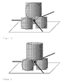
- FIG. 1a shows the embodiment of the example of three on the bottom plate movably supported balls and an additional seated ball.
- the arrows represent the fluid jets that meet at a common collision point.
- FIG. 1b shows a seated cylinder.
- the cylinder additionally has the advantage that the adjustment of the fluid jets is simpler than in the case of the ball. Furthermore, the cylinder may have an additional bore through which a further substance can be introduced into the reaction space.
- the number of movable balls resting on the bottom plate is at least three, corresponding to three fluid jets which collide at a common point.
- 4, 5 or 6 balls on the Floor plate according to, 4, 5 or 6 fluid jets.
- the bottom plate itself may have shell-like depressions in which the movable resting balls. This also stabilizes the position of the balls can be effected.
- the shell-like depression is advantageously dimensioned so that the ball dips into the depression to about 2.5% - 25% of the radius of the ball.
- Another object of the invention is a method for carrying out chemical and physical material conversions in which one sets a fluid medium under a pressure of 50 to 4000 bar and relaxed via the fluid inputs of the reactor according to the invention via nozzles to a common point of collision and via an opening in the Bottom plate and the bottom of the reactor out of the reactor passes.
- chemical and physical material transformations are meant, for example, homogenization, emulsification, particle comminution, disaggregation and deagglomeration.
- the inventive method is particularly suitable for the preparation of dispersions.
Landscapes
- Chemical & Material Sciences (AREA)
- Chemical Kinetics & Catalysis (AREA)
- Organic Chemistry (AREA)
- Physical Or Chemical Processes And Apparatus (AREA)
- Organic Low-Molecular-Weight Compounds And Preparation Thereof (AREA)
- Agricultural Chemicals And Associated Chemicals (AREA)
- Devices And Processes Conducted In The Presence Of Fluids And Solid Particles (AREA)
Abstract
Description
- Die Erfindung betrifft eine Vorrichtung und ein Verfahren zur Durchführung chemischer und physikalischer Stoffumwandlungen.
- Zur Herstellung feinteiliger Dispersionen stehen Vorrichtungen, wie Kugelmühlen oder Rührwerkskugelmühlen, zur Verfügung. Nachteilig bei diesen Vorrichtungen ist der Abrieb der eingesetzten Mahlkörper, zum Beispiel aus Glas, Keramik, Metall oder Sand. Dieser Abrieb schränkt die Verwendung der damit erzeugten Dispersionen in Bereichen, die nur geringe Verunreinigungen tolerieren, wie zum Beispiel das Polieren empfindlicher Oberflächen ein.
- Höhere Energieeinträge sind mit einem Planetenkneter/-mixer möglich. Die Wirksamkeit dieses Systems ist jedoch mit einer ausreichend hohen Viskosität der bearbeiteten Mischung verbunden, um die benötigten hohen Scherenergien zum Zerteilen der Teilchen einzubringen.
- Mit Hochdruckhomogenisatoren, bei denen eine unter einem hohen Druck stehende Vordispersion gegen gepanzerte Wandbereiche einer Kammer trifft, können zwar sehr feinteilige Dispersionen erzeugt werden, es hat sich jedoch gezeigt, dass die Kammer einer solche Vorrichtung trotz der Panzerung einem starken Verschleiß unterliegt. Die Teilung der Vordispersion in zwei Ströme, die über eine Düse entspannt werden und exakt aufeinandertreffen, reduziert den Abrieb, löst das Problem aber nicht. Insbesondere die Zentrierung der aufeinandergerichteten Vordispersionen ist schwierig. Ein solches Verfahren ist beispielsweise in
EP-A-766997 - In
EP-B-1165224 wird ein Verfahren beschrieben, bei dem der Abrieb bei der Herstellung von Dispersionen deutlich verringert wird, wenn die unter hohem Druck stehenden geteilten Vordispersionsströme auf einen gemeinsamen Kollisionspunkt entspannt werden, der sich in einem gasgefüllten, materialfernen Mahlraum befindet. Durch diese Anordnung soll die Kavitation an Materialwänden im Gegensatz zu den oben aufgeführten Hochdruckvorrichtungen, die in einem mit Flüssigkeit gefüllten Mahlraum arbeiten, minimiert werden. Der Gasstrom übernimmt dabei auch die Aufgabe die Dispersion aus dem Mahlraum zu transportieren und die Dispersion zu kühlen. Nachteilig bei diesem Verfahren ist die Aufarbeitung der Gas-Dispersionsgemische. Um wirtschaftlich vernünftige Durchsätze zu erzielen, müssen große Mengen an Gas eingesetzt werden. Die Abtrennung dieses Gases erfordert einen erhöhten apparativen Aufwand, wie zum Beispiel entsprechend dimensionierte Entgaser. Die aufgrund des hohen Gasanteils reduzierte Wärmeleitfähigkeit erfordert, beim gegebenenfalls erforderlichen Abkühlen des Gemisches, größer dimensionierte und damit teurere Kühlvorrichtungen. - In
DE-C-10204470 wird der Einsatz von Wasserdampf als Gas beschrieben. Die Kollision der zu dispergierenden Teilchen findet auch hier im materialfernen Raum statt. Durch den Einsatz von Wasserdampf können die Nachteile des Verfahrens gemäßEP-B-1165224 , bei dem große Mengen an Gas aus dem Reaktionsgemisch entfernt werden müssen, vermieden werden. Dennoch erweist sich auch bei dem VerfahrenDE-C-10204470 , dass die Aufrechterhaltung einer Gasatmosphäre während der Dispersion wirtschaftlich nicht sinnvoll ist. - In
DE-A-10360766 wird ein Verfahren beschrieben, bei dem der Mahlraum mit einer Vordispersion geflutet ist, wodurch die Aufarbeitung von Gemischen aus Gas und Dispersion vermieden werden kann. - In
DE-A-10114054 wird ein Reaktor beschrieben, bei dem nach der Justierung der Fluidstrahlen zusätzlich drehbar aufliegende Hartkörper, beispielsweise Keramikkugeln, in den Strahlengang eingebracht werden. Dies führt dazu, dass die Fluidstrahlen im Falle einer Dejustierung nicht auf die Reaktorwand trifft und zu einer Zerstörung des gesamten Reaktors führt, sondern lediglich auf die austauschbaren Keramikkugeln trifft. Es hat sich jedoch gezeigt, dass die Wirkung einer solchen Vorrichtung nur kurzfristig ist, da es durch die Bewegung der drehbar aufliegenden Hartkörper ebenfalls zu Abtragungen an den Stellen des Reaktors kommt, an der die Hartkörper aufliegen und an der Wandung anliegen. In Folge führt die dadurch hervorgerufene Dejustierung der Fluidstrahlen zu weiteren Schäden am Reaktor. - All die genannten Vorrichtungen, bei denen unter Hochdruck physikalische oder chemische Stoffumwandlungen vorgenommen werden, weisen den Nachteil auf, dass es unter den extremen Bedingungen zu einem Materialabtrag kommt. Hierdurch wird zum einen das Reaktionsprodukt verunreinigt, zum anderen ist ein solcher Reaktor nicht wirtschaftlich zu betreiben.
- Aufgabe der vorliegenden Erfindung war es daher, einen Reaktor bereitzustellen, mit dem unter hohem Druck physikalische oder chemische Stoffumwandlungen durchgeführt über einen langen Zeitraum durchgeführt werden können ohne dass es hierbei zu nennenswerten Materialabträgen und zu einer Dejustierung des Strahlenganges kommt.
- Die Aufgabe der Erfindung wird gelöst durch einen Reaktor zur Durchführung chemischer und physikalischer Stoffumwandlungen umfassend einen von einem Reaktorgehäuse umschlossenen Reaktionsraum, wobei
- das Reaktorgehäuse wenigstens zwei seitliche Fluideingänge mit justierbar gelagerten Düsen aufweist, die einen Winkel von etwa 20-160 Grad umfassen, und
- durch die Düsen Fluidstrahlen, die sich vorzugsweise in einer ebene befinden, geleitet werden, die in einem gemeinsamen Kollisionspunkt innerhalb des Reaktionsraumes aufeinandertreffen und
- der Reaktor einen Fluidausgang am Boden des Reaktionsraumes aufweist,
- auf dem Boden des Reaktionsraumes eine Bodenplatte aufliegt,
- · die eine Bohrung als Fluidausgang aufweist und
- · auf der sich beweglich aufliegende Kugeln befinden, die den ursprünglichen Fluidstrahlengang der einzelnen Strahlen im dejustierten Zustand blockieren und
- sich jeweils zwischen einer beweglich aufliegenden Kugel und der Wandung des Reaktionsraumes sich eine auf dem Boden des Reaktionsraumes aufstehende Halbschale befindet und
- Bodenplatte, Halbschale und beweglich aufliegende Kugeln aus einem oder mehreren Hartstoffen bestehen.
- Der erfindungsgemäße Reaktor bewirkt, dass sich die beweglich aufliegenden Kugeln nur in Kontakt mit der aus einem Hartstoff bestehenden Bodenplatte und Halbschale befinden. Dabei kann die auf dem Boden des Reaktionsraum aufliegende Bodenplatte und die Halbschalen austauschbar gestaltet sein, so dass nach sehr langen Reaktionszeiten ein einfacher Austausch möglich ist.
- Die Erfindung ermöglicht es, dass das eigentliche Reaktorgehäuse aus einem üblicherweise verwendeten Material, beispielsweise Edelstahl, bestehen kann, während nur Bodenplatte, Halbschale und beweglich aufliegende Kugeln aus einem oder mehreren Hartstoffen bestehen.
- Unter einem Hartstoff gemäß der Erfindung ist ein Stoff zu verstehen, dessen Mohs-Härte wenigstens 7,5, bevorzugt wenigstens 8 beträgt. Geeignet sind insbesondere gehärtete Metalle, Metallcarbide, Metallnitride, Metallboride, Borcarbid und Zircondioxid, Korund und Saphir.
- In einer bevorzugten Ausführungsform bestehen die auf dem Reaktorboden aufliegende Bodenplatte und die Halbschalen aus gekennzeichnet, dass es sich bei dem Hartstoff um Wolframcarbidpartikel in einer Nickel- oder Kobaltmatrix handelt. Diese Material zeichnen sich auch dadurch aus, dass sie durch Erosionsverfahren, wie Draht- und Senkerosion, relativ einfach zu bearbeiten sind. Aufgrund der hohen chemischen Beständigkeit sind Wolframcarbidpartikel in einer Nickelmatrix besonders bevorzugt.
- Die beweglich aufliegenden Kugeln bestehen bevorzugt aus Korund, Saphir, Rubin oder Metallnitriden als Hartstoff. Besonders bevorzugt kann Siliciumnitrid sein.
- In einer besonderen Ausführungsform des erfindungsgemäßen Reaktors befindet sich auf den auf der Bodenplatte beweglich aufliegenden Kugeln eine weitere Kugel oder ein Zylinder. Die Kugel oder der Zylinder sind so dimensioniert, dass sie mit den auf der Bodenplatte aufliegenden beweglichen Kugeln jeweils einen Kontaktpunkt aufweisen. Kugel und Zylinder stabilisieren die Lage der auf der Bodenplatte aufliegenden, beweglichen Kugeln. Eine weitere Stabilisierung kann durch eine Federbelastung der aufliegenden Kugel erreicht werden.
- In einer besonderen Ausführungsform kann der Zylinder mit einer Bohrung von Stirnfläche zu Stirnfläche versehen sein, so dass durch diese Bohrung ein weiteres Fluid oder Gas direkt auf den Kollisionspunkt gerichtet werden kann und dadurch zusätzlich physikalische oder chemische Stoffumwandlungen erzielt werden können.
- Die Kugeln bestehen vorteilhafterweise ebenfalls aus einem Hartstoff.
-
Figur 1a zeigt die Ausführungsform am Beispiel dreier auf der Bodenplatte beweglich aufliegenden Kugeln und einer zusätzlichen aufsitzenden Kugel. Die Pfeile stellen die Fluidstrahlen dar, die sich auf einem gemeinsamen Kollisionspunkt treffen.Figur 1b zeigt einen aufsitzenden Zylinder. - Der Zylinder weist zusätzlich den Vorteil auf, dass die Justierung der Fluidstrahlen einfacher ist, als im Falle der Kugel. Weiterhin kann der Zylinder eine zusätzliche Bohrung aufweisen, über die ein weiterer Stoff in den Reaktionsraum eingebracht werden kann.
- Die Anzahl der Bodenplatte aufliegenden beweglichen Kugeln beträgt mindestens drei, entsprechend drei Fluidstrahlen, die auf einem gemeinsamen Punkt kollidieren. Es können jedoch beispielsweise 4, 5 oder 6 Kugeln auf der Bodenplatte aufliegen, entsprechend, 4, 5 oder 6 Fluidstrahlen.
- Die Bodenplatte selbst kann schalenartige Vertiefungen aufweisen in denen die beweglich aufliegenden Kugeln aufliegen. Auch hierdurch kann eine Stabilisierung der Lage der Kugeln bewirkt werden. Die schalenartige Vertiefung ist vorteilhafterweise so dimensioniert, dass die Kugel zu ca. 2,5 % - 25 % des Radius der Kugel in die Vertiefung eintaucht.
- Ein weiterer Gegenstand der Erfindung ist ein Verfahren zur Durchführung chemischer und physikalischer Stoffumwandlungen bei dem man ein fluides Medium unter einen Druck von 50 bis 4000 bar setzt und über die Fluideingänge des erfindungsgemäßen Reaktors über Düsen auf einen gemeinsamen Kollisionspunkt hin entspannt und über eine Öffnung in der Bodenplatte und dem Reaktorboden aus dem Reaktor leitet.
- Unter chemischen und physikalischen Stoffumwandlungen sind beispielsweise Homogenisierung, Emulgierung, Teilchenzerkleinerung, Disaggregation und Deagglomeration zu verstehen.
- Das erfindungsgemäße Verfahren eignet sich besonders zur Herstellung von Dispersionen.
-
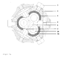
Figur 2a zeigt einen Querschnitt durch einen erfindungsgemäßen Reaktor mit: - 1 =
- Reaktorgehäuse
- 2 =
- Bodenplatte
- 3a =
- auf Bodenplatte aufliegende, bewegliche Kugel (gestrichelte Linie),
- 3b =
- Rand der Vertiefung in der die bewegliche Kugel auf der Bodenplatte aufliegt (durchgezogener Kreis)
- 4 =
- Halbschale
- 5 =
- Fluidausgang
- 6 =
- Fluideingang
- 7 =
- verschlossene Fluidausgänge
-
Figur 2b zeigt einen Längsschnitt durch einen erfindungsgemäßen Reaktor mit - 1 =
- Reaktorgehäuse
- 2 =
- Bodenplatte
- 3 =
- auf Bodenplatte aufliegende, bewegliche Kugel
- 4 =
- Halbschale
- 5 =
- aufliegende Kugel
- 6 =
- Fluideingang
- 7 =
- verschlossene Fluidausgänge,
- 8 =
- Fluidausgang,
- 9 =
- Feder.
Claims (6)
- Reaktor zur Durchführung chemischer und physikalischer Stoffumwandlungen umfassend einen von einem Reaktorgehäuse umschlossenen Reaktionsraum, wobei das Reaktorgehäuse wenigstens zwei seitliche Fluideingänge mit justierbar gelagerten Düsen aufweist, die einen Winkel von etwa 20-160 Grad umfassen, und durch die Fluidstrahlen geleitet werden, die in einem gemeinsamen Kollisionspunkt innerhalb des Reaktionsraumes aufeinandertreffen und einen Fluidausgang am Boden des Reaktionsraumes aufweist,
dadurch gekennzeichnet, dass- auf dem Boden des Reaktionsraumes eine austauschbare Bodenplatte aufliegt,· die eine Bohrung als Fluidausgang aufweist und· auf der sich beweglich aufliegende Kugeln befinden, die den ursprünglichen Fluidstrahlengang der einzelnen Strahlen im dejustierten Zustand blockieren und- sich jeweils zwischen einer beweglich aufliegenden Kugel und der Wandung des Reaktionsraumes sich eine auf dem Boden des Reaktionsraumes aufstehende Halbschale befindet und- Bodenplatte, Halbschale und beweglich aufliegende Kugeln aus einem oder mehreren Hartstoffen bestehen. - Reaktor nach Anspruch 1, dadurch gekennzeichnet, dass es sich bei dem Hartstoff der Bodenplatte und der Halbschale um Wolframcarbidpartikel in einer Nickelmatrix oder Kobaltmatrix handelt.
- Reaktor nach den Ansprüchen 1 oder 2, dadurch gekennzeichnet, dass auf den auf der Bodenplatte beweglich aufliegenden Kugeln eine weitere Kugel oder ein Zylinder aufliegt.
- Reaktor nach den Ansprüchen 1 bis 3, dadurch gekennzeichnet, dass die Bodenplatte schalenartige Vertiefungen aufweist in denen die beweglich aufliegenden Kugeln aufliegen.
- Reaktor nach den Ansprüchen 1 bis 4, dadurch gekennzeichnet, dass die sich die in der Reaktorwandung befindlichen Fluideingänge in einer Ebene befinden.
- Verfahren zur Durchführung chemischer und physikalischer Stoffumwandlungen bei dem man ein fluides Medium unter einen Druck von 50 bis 4000 bar setzt und über die Fluideingänge des Reaktors gemäß der Ansprüche 1 bis 5 über Düsen auf einen gemeinsamen Kollisionspunkt hin entspannt und über eine Öffnung in der Bodenplatte und dem Reaktorboden aus dem Reaktor leitet.
Priority Applications (8)
| Application Number | Priority Date | Filing Date | Title |
|---|---|---|---|
| EP08103331A EP2106850B1 (de) | 2008-04-02 | 2008-04-02 | Vorrichtung und Verfahren zur Durchführung chemischer und physikalischer Stoffumwandlungen |
| ES08103331T ES2355967T3 (es) | 2008-04-02 | 2008-04-02 | Dispositivo y procedimiento para llevar a cabo conversiones químicas y físicas de materiales. |
| DE502008001884T DE502008001884D1 (de) | 2008-04-02 | 2008-04-02 | Vorrichtung und Verfahren zur Durchführung chemischer und physikalischer Stoffumwandlungen |
| AT08103331T ATE489164T1 (de) | 2008-04-02 | 2008-04-02 | Vorrichtung und verfahren zur durchführung chemischer und physikalischer stoffumwandlungen |
| PCT/EP2009/052582 WO2009121681A1 (en) | 2008-04-02 | 2009-03-05 | Apparatus and method for carrying out chemical and physical materials transformations |
| US12/920,498 US8313703B2 (en) | 2008-04-02 | 2009-03-05 | Apparatus and method for carrying out chemical and physical materials transformations |
| JP2011502317A JP5335066B2 (ja) | 2008-04-02 | 2009-03-05 | 化学的及び物理的な変態を行うための装置及び方法 |
| CN2009801114666A CN101980774B (zh) | 2008-04-02 | 2009-03-05 | 用于进行材料的物理转化和化学转化的装置和方法 |
Applications Claiming Priority (1)
| Application Number | Priority Date | Filing Date | Title |
|---|---|---|---|
| EP08103331A EP2106850B1 (de) | 2008-04-02 | 2008-04-02 | Vorrichtung und Verfahren zur Durchführung chemischer und physikalischer Stoffumwandlungen |
Publications (2)
| Publication Number | Publication Date |
|---|---|
| EP2106850A1 true EP2106850A1 (de) | 2009-10-07 |
| EP2106850B1 EP2106850B1 (de) | 2010-11-24 |
Family
ID=39773091
Family Applications (1)
| Application Number | Title | Priority Date | Filing Date |
|---|---|---|---|
| EP08103331A Active EP2106850B1 (de) | 2008-04-02 | 2008-04-02 | Vorrichtung und Verfahren zur Durchführung chemischer und physikalischer Stoffumwandlungen |
Country Status (8)
| Country | Link |
|---|---|
| US (1) | US8313703B2 (de) |
| EP (1) | EP2106850B1 (de) |
| JP (1) | JP5335066B2 (de) |
| CN (1) | CN101980774B (de) |
| AT (1) | ATE489164T1 (de) |
| DE (1) | DE502008001884D1 (de) |
| ES (1) | ES2355967T3 (de) |
| WO (1) | WO2009121681A1 (de) |
Families Citing this family (2)
| Publication number | Priority date | Publication date | Assignee | Title |
|---|---|---|---|---|
| CN102430380B (zh) * | 2010-09-29 | 2014-08-06 | 张小丁 | 流体激波反应器 |
| CN103979619A (zh) * | 2014-04-30 | 2014-08-13 | 浙江工业大学 | 一种撞击流空化器 |
Citations (8)
| Publication number | Priority date | Publication date | Assignee | Title |
|---|---|---|---|---|
| EP0766997A1 (de) | 1995-10-02 | 1997-04-09 | Bayer Ag | Verfahren und Vorrichtung zur Herstellung von feinteiligen Feststoffdispersionen |
| US6173798B1 (en) * | 1999-02-23 | 2001-01-16 | Kennametal Inc. | Tungsten carbide nickel- chromium alloy hard member and tools using the same |
| EP1165224B1 (de) | 1999-04-08 | 2002-09-18 | Bernd Penth | Verfahren und vorrichtung zur durchführung chemischer und physikalischer prozesse |
| DE10114054A1 (de) | 2001-03-15 | 2002-09-26 | Volkswagen Ag | Verfahren zur Anhebung einer Abgastemperatur einer fremdgezündeten, direkteinspritzenden Verbrennungskraftmaschine |
| DE10141054A1 (de) * | 2001-08-22 | 2003-03-06 | Bernd Penth | Strahlreaktor und dessen Justierung |
| DE10204470C1 (de) | 2002-02-05 | 2003-08-14 | Degussa | Verfahren und Vorrichtung zur Herstellung von Dispersionen |
| DE10360766A1 (de) | 2003-12-23 | 2005-07-28 | Degussa Ag | Verfahren und Vorrichtung zur Herstellung von Dispersionen |
| GB2433747A (en) * | 2005-12-29 | 2007-07-04 | Schlumberger Holdings | An abrasion resistant coating |
Family Cites Families (8)
| Publication number | Priority date | Publication date | Assignee | Title |
|---|---|---|---|---|
| US2327402A (en) * | 1940-06-10 | 1943-08-24 | Clarkiron Inc | Grinding mill |
| US2974886A (en) * | 1959-01-08 | 1961-03-14 | Nagel Theodore | Apparatus for the shattering of solid particles |
| US3701484A (en) * | 1970-11-20 | 1972-10-31 | Johns Manville | Apparatus and process for suspending solids |
| FI74222C (fi) * | 1985-09-18 | 1988-01-11 | Finnpulva Ab Oy | Kvarnhus foer tryckammarkvarn. |
| US5082633A (en) * | 1990-06-14 | 1992-01-21 | The Dow Chemical Company | Mix head for mixing reactive chemicals |
| US5562253A (en) * | 1995-03-23 | 1996-10-08 | Xerox Corporation | Throughput efficiency enhancement of fluidized bed jet mill |
| US6138931A (en) * | 1999-07-27 | 2000-10-31 | Xerox Corporation | Apparatus and method for grinding particulate material |
| BR0314035A (pt) * | 2002-09-05 | 2005-07-12 | Boehringer Ingelheim Pharma | Aparelho para descarga de lìquidos, cartuchos para apropriados para este aparelho, e sistema consistindo no aparelho para a descarga de lìquidos e no cartucho |
-
2008
- 2008-04-02 AT AT08103331T patent/ATE489164T1/de active
- 2008-04-02 DE DE502008001884T patent/DE502008001884D1/de active Active
- 2008-04-02 ES ES08103331T patent/ES2355967T3/es active Active
- 2008-04-02 EP EP08103331A patent/EP2106850B1/de active Active
-
2009
- 2009-03-05 WO PCT/EP2009/052582 patent/WO2009121681A1/en not_active Ceased
- 2009-03-05 CN CN2009801114666A patent/CN101980774B/zh active Active
- 2009-03-05 JP JP2011502317A patent/JP5335066B2/ja active Active
- 2009-03-05 US US12/920,498 patent/US8313703B2/en active Active
Patent Citations (8)
| Publication number | Priority date | Publication date | Assignee | Title |
|---|---|---|---|---|
| EP0766997A1 (de) | 1995-10-02 | 1997-04-09 | Bayer Ag | Verfahren und Vorrichtung zur Herstellung von feinteiligen Feststoffdispersionen |
| US6173798B1 (en) * | 1999-02-23 | 2001-01-16 | Kennametal Inc. | Tungsten carbide nickel- chromium alloy hard member and tools using the same |
| EP1165224B1 (de) | 1999-04-08 | 2002-09-18 | Bernd Penth | Verfahren und vorrichtung zur durchführung chemischer und physikalischer prozesse |
| DE10114054A1 (de) | 2001-03-15 | 2002-09-26 | Volkswagen Ag | Verfahren zur Anhebung einer Abgastemperatur einer fremdgezündeten, direkteinspritzenden Verbrennungskraftmaschine |
| DE10141054A1 (de) * | 2001-08-22 | 2003-03-06 | Bernd Penth | Strahlreaktor und dessen Justierung |
| DE10204470C1 (de) | 2002-02-05 | 2003-08-14 | Degussa | Verfahren und Vorrichtung zur Herstellung von Dispersionen |
| DE10360766A1 (de) | 2003-12-23 | 2005-07-28 | Degussa Ag | Verfahren und Vorrichtung zur Herstellung von Dispersionen |
| GB2433747A (en) * | 2005-12-29 | 2007-07-04 | Schlumberger Holdings | An abrasion resistant coating |
Also Published As
| Publication number | Publication date |
|---|---|
| CN101980774A (zh) | 2011-02-23 |
| CN101980774B (zh) | 2013-08-28 |
| JP2011516245A (ja) | 2011-05-26 |
| WO2009121681A1 (en) | 2009-10-08 |
| JP5335066B2 (ja) | 2013-11-06 |
| ES2355967T3 (es) | 2011-04-01 |
| US8313703B2 (en) | 2012-11-20 |
| US20110015281A1 (en) | 2011-01-20 |
| ATE489164T1 (de) | 2010-12-15 |
| EP2106850B1 (de) | 2010-11-24 |
| DE502008001884D1 (de) | 2011-01-05 |
Similar Documents
| Publication | Publication Date | Title |
|---|---|---|
| DE10204470C1 (de) | Verfahren und Vorrichtung zur Herstellung von Dispersionen | |
| DE10360766A1 (de) | Verfahren und Vorrichtung zur Herstellung von Dispersionen | |
| EP1165224B1 (de) | Verfahren und vorrichtung zur durchführung chemischer und physikalischer prozesse | |
| DE19640027B4 (de) | Verfahren und Vorrichtung zum Pulverisieren fester Teilchen | |
| DE19728382C2 (de) | Verfahren und Vorrichtung zur Fließbett-Strahlmahlung | |
| EP2106850B1 (de) | Vorrichtung und Verfahren zur Durchführung chemischer und physikalischer Stoffumwandlungen | |
| EP2055386A1 (de) | Verfahren und Vorrichtung zur Feinstmahlung von Feststoffen | |
| EP0683824A1 (de) | Verfarhen zum granulieren und zerkleinern von schmelzflüssigem material und mahlgut sowie einrichtung zur durchführung dieses verfahrens | |
| EP3079827B1 (de) | Mahlvorrichtung mit verschleissscheibe | |
| WO2023208337A1 (de) | Vorrichtungen und verfahren zum mischen von gasen | |
| EP2583790B1 (de) | Strahlschneidvorrichtung | |
| EP1337340A1 (de) | Verfahren und vorrichtung zum zerkleinern von partikeln | |
| DE10141054A1 (de) | Strahlreaktor und dessen Justierung | |
| DE400307C (de) | Verfahren und Vorrichtung zur Herstellung feiner Pulver bis herab zur kolloidalen Feinheit, vornehmlich aus Metallen | |
| DE102022201367A1 (de) | Verfahren und Strahlmühle zum überkritischen Strahlmahlen | |
| DE10045172B4 (de) | Verfahren und Vorrichtung zum Zerkleinern von Partikeln | |
| EP3180163B1 (de) | Strahlschneidvorrichtung und strahlschneidverfahren | |
| DE2828053A1 (de) | Verfahren und vorrichtung zur herstellung aktivierter gemische aus vorzugsweise pulverfoermigen komponenten, welche zur weiterbearbeitung durch pressen und nachfolgendes sintern bestimmt ist | |
| EP4663286A1 (de) | Verfahren und vorrichtung zur bearbeitung von ausgangsstoffen | |
| DE112018004532T5 (de) | Vorrichtung und Verfahren zum kryogenen Mahlen mit konfluenten Düsenstrahlen (Jets) | |
| EP2512737B1 (de) | Verfahren und vorrichtung zum reinigen, aktivieren und vorbehandeln eines werkstücks mittels kohlendioxidschneepartikeln | |
| DE704322C (de) | Verfahren und Vorrichtung zur Behandlung von Stoffen zum Zwecke der Zerkleinerung | |
| DE102019112791B3 (de) | Schleifvorrichtung zum verrunden von partikeln | |
| DE10037301A1 (de) | Mikrostrahlreaktor | |
| DE19513086A1 (de) | Verfahren zur Zerkleinerung von Partikeln mit Hilfe von Hochgeschwindigkeitsflüssigkeitsstrahlen |
Legal Events
| Date | Code | Title | Description |
|---|---|---|---|
| PUAI | Public reference made under article 153(3) epc to a published international application that has entered the european phase |
Free format text: ORIGINAL CODE: 0009012 |
|
| 17P | Request for examination filed |
Effective date: 20080402 |
|
| AK | Designated contracting states |
Kind code of ref document: A1 Designated state(s): AT BE BG CH CY CZ DE DK EE ES FI FR GB GR HR HU IE IS IT LI LT LU LV MC MT NL NO PL PT RO SE SI SK TR |
|
| AX | Request for extension of the european patent |
Extension state: AL BA MK RS |
|
| AKX | Designation fees paid |
Designated state(s): AT BE BG CH CY CZ DE DK EE ES FI FR GB GR HR HU IE IS IT LI LT LU LV MC MT NL NO PL PT RO SE SI SK TR |
|
| GRAP | Despatch of communication of intention to grant a patent |
Free format text: ORIGINAL CODE: EPIDOSNIGR1 |
|
| RIC1 | Information provided on ipc code assigned before grant |
Ipc: B01J 19/26 20060101ALI20100706BHEP Ipc: B01F 5/02 20060101ALI20100706BHEP Ipc: B01J 19/02 20060101ALI20100706BHEP Ipc: B01J 19/00 20060101AFI20100706BHEP |
|
| GRAS | Grant fee paid |
Free format text: ORIGINAL CODE: EPIDOSNIGR3 |
|
| GRAA | (expected) grant |
Free format text: ORIGINAL CODE: 0009210 |
|
| AK | Designated contracting states |
Kind code of ref document: B1 Designated state(s): AT BE BG CH CY CZ DE DK EE ES FI FR GB GR HR HU IE IS IT LI LT LU LV MC MT NL NO PL PT RO SE SI SK TR |
|
| REG | Reference to a national code |
Ref country code: GB Ref legal event code: FG4D Free format text: NOT ENGLISH |
|
| REG | Reference to a national code |
Ref country code: CH Ref legal event code: EP |
|
| REG | Reference to a national code |
Ref country code: IE Ref legal event code: FG4D |
|
| REF | Corresponds to: |
Ref document number: 502008001884 Country of ref document: DE Date of ref document: 20110105 Kind code of ref document: P |
|
| REG | Reference to a national code |
Ref country code: NL Ref legal event code: VDEP Effective date: 20101124 |
|
| REG | Reference to a national code |
Ref country code: ES Ref legal event code: FG2A Ref document number: 2355967 Country of ref document: ES Kind code of ref document: T3 Effective date: 20110401 |
|
| LTIE | Lt: invalidation of european patent or patent extension |
Effective date: 20101124 |
|
| PG25 | Lapsed in a contracting state [announced via postgrant information from national office to epo] |
Ref country code: LT Free format text: LAPSE BECAUSE OF FAILURE TO SUBMIT A TRANSLATION OF THE DESCRIPTION OR TO PAY THE FEE WITHIN THE PRESCRIBED TIME-LIMIT Effective date: 20101124 Ref country code: NO Free format text: LAPSE BECAUSE OF FAILURE TO SUBMIT A TRANSLATION OF THE DESCRIPTION OR TO PAY THE FEE WITHIN THE PRESCRIBED TIME-LIMIT Effective date: 20110224 |
|
| PG25 | Lapsed in a contracting state [announced via postgrant information from national office to epo] |
Ref country code: SE Free format text: LAPSE BECAUSE OF FAILURE TO SUBMIT A TRANSLATION OF THE DESCRIPTION OR TO PAY THE FEE WITHIN THE PRESCRIBED TIME-LIMIT Effective date: 20101124 Ref country code: CY Free format text: LAPSE BECAUSE OF FAILURE TO SUBMIT A TRANSLATION OF THE DESCRIPTION OR TO PAY THE FEE WITHIN THE PRESCRIBED TIME-LIMIT Effective date: 20101124 Ref country code: LV Free format text: LAPSE BECAUSE OF FAILURE TO SUBMIT A TRANSLATION OF THE DESCRIPTION OR TO PAY THE FEE WITHIN THE PRESCRIBED TIME-LIMIT Effective date: 20101124 Ref country code: FI Free format text: LAPSE BECAUSE OF FAILURE TO SUBMIT A TRANSLATION OF THE DESCRIPTION OR TO PAY THE FEE WITHIN THE PRESCRIBED TIME-LIMIT Effective date: 20101124 Ref country code: BG Free format text: LAPSE BECAUSE OF FAILURE TO SUBMIT A TRANSLATION OF THE DESCRIPTION OR TO PAY THE FEE WITHIN THE PRESCRIBED TIME-LIMIT Effective date: 20110224 Ref country code: HR Free format text: LAPSE BECAUSE OF FAILURE TO SUBMIT A TRANSLATION OF THE DESCRIPTION OR TO PAY THE FEE WITHIN THE PRESCRIBED TIME-LIMIT Effective date: 20101124 Ref country code: IS Free format text: LAPSE BECAUSE OF FAILURE TO SUBMIT A TRANSLATION OF THE DESCRIPTION OR TO PAY THE FEE WITHIN THE PRESCRIBED TIME-LIMIT Effective date: 20110324 Ref country code: NL Free format text: LAPSE BECAUSE OF FAILURE TO SUBMIT A TRANSLATION OF THE DESCRIPTION OR TO PAY THE FEE WITHIN THE PRESCRIBED TIME-LIMIT Effective date: 20101124 Ref country code: PT Free format text: LAPSE BECAUSE OF FAILURE TO SUBMIT A TRANSLATION OF THE DESCRIPTION OR TO PAY THE FEE WITHIN THE PRESCRIBED TIME-LIMIT Effective date: 20110324 Ref country code: SI Free format text: LAPSE BECAUSE OF FAILURE TO SUBMIT A TRANSLATION OF THE DESCRIPTION OR TO PAY THE FEE WITHIN THE PRESCRIBED TIME-LIMIT Effective date: 20101124 |
|
| REG | Reference to a national code |
Ref country code: IE Ref legal event code: FD4D |
|
| PG25 | Lapsed in a contracting state [announced via postgrant information from national office to epo] |
Ref country code: GR Free format text: LAPSE BECAUSE OF FAILURE TO SUBMIT A TRANSLATION OF THE DESCRIPTION OR TO PAY THE FEE WITHIN THE PRESCRIBED TIME-LIMIT Effective date: 20110225 |
|
| PG25 | Lapsed in a contracting state [announced via postgrant information from national office to epo] |
Ref country code: IE Free format text: LAPSE BECAUSE OF FAILURE TO SUBMIT A TRANSLATION OF THE DESCRIPTION OR TO PAY THE FEE WITHIN THE PRESCRIBED TIME-LIMIT Effective date: 20101124 Ref country code: CZ Free format text: LAPSE BECAUSE OF FAILURE TO SUBMIT A TRANSLATION OF THE DESCRIPTION OR TO PAY THE FEE WITHIN THE PRESCRIBED TIME-LIMIT Effective date: 20101124 Ref country code: EE Free format text: LAPSE BECAUSE OF FAILURE TO SUBMIT A TRANSLATION OF THE DESCRIPTION OR TO PAY THE FEE WITHIN THE PRESCRIBED TIME-LIMIT Effective date: 20101124 |
|
| PG25 | Lapsed in a contracting state [announced via postgrant information from national office to epo] |
Ref country code: PL Free format text: LAPSE BECAUSE OF FAILURE TO SUBMIT A TRANSLATION OF THE DESCRIPTION OR TO PAY THE FEE WITHIN THE PRESCRIBED TIME-LIMIT Effective date: 20101124 Ref country code: SK Free format text: LAPSE BECAUSE OF FAILURE TO SUBMIT A TRANSLATION OF THE DESCRIPTION OR TO PAY THE FEE WITHIN THE PRESCRIBED TIME-LIMIT Effective date: 20101124 Ref country code: DK Free format text: LAPSE BECAUSE OF FAILURE TO SUBMIT A TRANSLATION OF THE DESCRIPTION OR TO PAY THE FEE WITHIN THE PRESCRIBED TIME-LIMIT Effective date: 20101124 Ref country code: RO Free format text: LAPSE BECAUSE OF FAILURE TO SUBMIT A TRANSLATION OF THE DESCRIPTION OR TO PAY THE FEE WITHIN THE PRESCRIBED TIME-LIMIT Effective date: 20101124 |
|
| PLBE | No opposition filed within time limit |
Free format text: ORIGINAL CODE: 0009261 |
|
| STAA | Information on the status of an ep patent application or granted ep patent |
Free format text: STATUS: NO OPPOSITION FILED WITHIN TIME LIMIT |
|
| BERE | Be: lapsed |
Owner name: EVONIK DEGUSSA G.M.B.H. Effective date: 20110430 |
|
| 26N | No opposition filed |
Effective date: 20110825 |
|
| PG25 | Lapsed in a contracting state [announced via postgrant information from national office to epo] |
Ref country code: MC Free format text: LAPSE BECAUSE OF NON-PAYMENT OF DUE FEES Effective date: 20110430 |
|
| REG | Reference to a national code |
Ref country code: DE Ref legal event code: R097 Ref document number: 502008001884 Country of ref document: DE Effective date: 20110825 |
|
| PG25 | Lapsed in a contracting state [announced via postgrant information from national office to epo] |
Ref country code: MT Free format text: LAPSE BECAUSE OF FAILURE TO SUBMIT A TRANSLATION OF THE DESCRIPTION OR TO PAY THE FEE WITHIN THE PRESCRIBED TIME-LIMIT Effective date: 20101124 |
|
| PG25 | Lapsed in a contracting state [announced via postgrant information from national office to epo] |
Ref country code: BE Free format text: LAPSE BECAUSE OF NON-PAYMENT OF DUE FEES Effective date: 20110430 |
|
| PG25 | Lapsed in a contracting state [announced via postgrant information from national office to epo] |
Ref country code: LU Free format text: LAPSE BECAUSE OF NON-PAYMENT OF DUE FEES Effective date: 20110402 |
|
| PG25 | Lapsed in a contracting state [announced via postgrant information from national office to epo] |
Ref country code: TR Free format text: LAPSE BECAUSE OF FAILURE TO SUBMIT A TRANSLATION OF THE DESCRIPTION OR TO PAY THE FEE WITHIN THE PRESCRIBED TIME-LIMIT Effective date: 20101124 |
|
| PG25 | Lapsed in a contracting state [announced via postgrant information from national office to epo] |
Ref country code: HU Free format text: LAPSE BECAUSE OF FAILURE TO SUBMIT A TRANSLATION OF THE DESCRIPTION OR TO PAY THE FEE WITHIN THE PRESCRIBED TIME-LIMIT Effective date: 20101124 |
|
| REG | Reference to a national code |
Ref country code: AT Ref legal event code: MM01 Ref document number: 489164 Country of ref document: AT Kind code of ref document: T Effective date: 20130402 |
|
| PG25 | Lapsed in a contracting state [announced via postgrant information from national office to epo] |
Ref country code: AT Free format text: LAPSE BECAUSE OF NON-PAYMENT OF DUE FEES Effective date: 20130402 |
|
| REG | Reference to a national code |
Ref country code: FR Ref legal event code: PLFP Year of fee payment: 9 |
|
| REG | Reference to a national code |
Ref country code: FR Ref legal event code: PLFP Year of fee payment: 10 |
|
| REG | Reference to a national code |
Ref country code: FR Ref legal event code: PLFP Year of fee payment: 11 |
|
| REG | Reference to a national code |
Ref country code: DE Ref legal event code: R081 Ref document number: 502008001884 Country of ref document: DE Owner name: EVONIK OPERATIONS GMBH, DE Free format text: FORMER OWNER: EVONIK DEGUSSA GMBH, 45128 ESSEN, DE |
|
| REG | Reference to a national code |
Ref country code: CH Ref legal event code: PFA Owner name: EVONIK OPERATIONS GMBH, DE Free format text: FORMER OWNER: EVONIK DEGUSSA GMBH, DE |
|
| REG | Reference to a national code |
Ref country code: ES Ref legal event code: PC2A Owner name: EVONIK OPERATIONS GMBH Effective date: 20200623 |
|
| P01 | Opt-out of the competence of the unified patent court (upc) registered |
Effective date: 20230526 |
|
| PGFP | Annual fee paid to national office [announced via postgrant information from national office to epo] |
Ref country code: CH Payment date: 20240501 Year of fee payment: 17 |
|
| PGFP | Annual fee paid to national office [announced via postgrant information from national office to epo] |
Ref country code: ES Payment date: 20240524 Year of fee payment: 17 |
|
| PGFP | Annual fee paid to national office [announced via postgrant information from national office to epo] |
Ref country code: IT Payment date: 20240424 Year of fee payment: 17 |
|
| PGFP | Annual fee paid to national office [announced via postgrant information from national office to epo] |
Ref country code: DE Payment date: 20250422 Year of fee payment: 18 |
|
| PGFP | Annual fee paid to national office [announced via postgrant information from national office to epo] |
Ref country code: GB Payment date: 20250418 Year of fee payment: 18 |
|
| PGFP | Annual fee paid to national office [announced via postgrant information from national office to epo] |
Ref country code: FR Payment date: 20250424 Year of fee payment: 18 |
|
| REG | Reference to a national code |
Ref country code: CH Ref legal event code: H13 Free format text: ST27 STATUS EVENT CODE: U-0-0-H10-H13 (AS PROVIDED BY THE NATIONAL OFFICE) Effective date: 20251125 |
|
| PG25 | Lapsed in a contracting state [announced via postgrant information from national office to epo] |
Ref country code: CH Free format text: LAPSE BECAUSE OF NON-PAYMENT OF DUE FEES Effective date: 20250430 |
|
| PG25 | Lapsed in a contracting state [announced via postgrant information from national office to epo] |
Ref country code: IT Free format text: LAPSE BECAUSE OF NON-PAYMENT OF DUE FEES Effective date: 20250402 |