EP2106513B1 - Konstantträger - Google Patents
Konstantträger Download PDFInfo
- Publication number
- EP2106513B1 EP2106513B1 EP07866284A EP07866284A EP2106513B1 EP 2106513 B1 EP2106513 B1 EP 2106513B1 EP 07866284 A EP07866284 A EP 07866284A EP 07866284 A EP07866284 A EP 07866284A EP 2106513 B1 EP2106513 B1 EP 2106513B1
- Authority
- EP
- European Patent Office
- Prior art keywords
- load
- spring
- force
- cam
- carrying
- Prior art date
- Legal status (The legal status is an assumption and is not a legal conclusion. Google has not performed a legal analysis and makes no representation as to the accuracy of the status listed.)
- Active
Links
Images


Classifications
-
- F—MECHANICAL ENGINEERING; LIGHTING; HEATING; WEAPONS; BLASTING
- F16—ENGINEERING ELEMENTS AND UNITS; GENERAL MEASURES FOR PRODUCING AND MAINTAINING EFFECTIVE FUNCTIONING OF MACHINES OR INSTALLATIONS; THERMAL INSULATION IN GENERAL
- F16L—PIPES; JOINTS OR FITTINGS FOR PIPES; SUPPORTS FOR PIPES, CABLES OR PROTECTIVE TUBING; MEANS FOR THERMAL INSULATION IN GENERAL
- F16L58/00—Protection of pipes or pipe fittings against corrosion or incrustation
-
- F—MECHANICAL ENGINEERING; LIGHTING; HEATING; WEAPONS; BLASTING
- F16—ENGINEERING ELEMENTS AND UNITS; GENERAL MEASURES FOR PRODUCING AND MAINTAINING EFFECTIVE FUNCTIONING OF MACHINES OR INSTALLATIONS; THERMAL INSULATION IN GENERAL
- F16L—PIPES; JOINTS OR FITTINGS FOR PIPES; SUPPORTS FOR PIPES, CABLES OR PROTECTIVE TUBING; MEANS FOR THERMAL INSULATION IN GENERAL
- F16L3/00—Supports for pipes, cables or protective tubing, e.g. hangers, holders, clamps, cleats, clips, brackets
- F16L3/16—Supports for pipes, cables or protective tubing, e.g. hangers, holders, clamps, cleats, clips, brackets with special provision allowing movement of the pipe
- F16L3/20—Supports for pipes, cables or protective tubing, e.g. hangers, holders, clamps, cleats, clips, brackets with special provision allowing movement of the pipe allowing movement in transverse direction
- F16L3/205—Supports for pipes, cables or protective tubing, e.g. hangers, holders, clamps, cleats, clips, brackets with special provision allowing movement of the pipe allowing movement in transverse direction having supporting springs
- F16L3/21—Supports for pipes, cables or protective tubing, e.g. hangers, holders, clamps, cleats, clips, brackets with special provision allowing movement of the pipe allowing movement in transverse direction having supporting springs providing constant supporting spring force
-
- F—MECHANICAL ENGINEERING; LIGHTING; HEATING; WEAPONS; BLASTING
- F16—ENGINEERING ELEMENTS AND UNITS; GENERAL MEASURES FOR PRODUCING AND MAINTAINING EFFECTIVE FUNCTIONING OF MACHINES OR INSTALLATIONS; THERMAL INSULATION IN GENERAL
- F16L—PIPES; JOINTS OR FITTINGS FOR PIPES; SUPPORTS FOR PIPES, CABLES OR PROTECTIVE TUBING; MEANS FOR THERMAL INSULATION IN GENERAL
- F16L3/00—Supports for pipes, cables or protective tubing, e.g. hangers, holders, clamps, cleats, clips, brackets
- F16L3/16—Supports for pipes, cables or protective tubing, e.g. hangers, holders, clamps, cleats, clips, brackets with special provision allowing movement of the pipe
- F16L3/20—Supports for pipes, cables or protective tubing, e.g. hangers, holders, clamps, cleats, clips, brackets with special provision allowing movement of the pipe allowing movement in transverse direction
- F16L3/205—Supports for pipes, cables or protective tubing, e.g. hangers, holders, clamps, cleats, clips, brackets with special provision allowing movement of the pipe allowing movement in transverse direction having supporting springs
- F16L3/2056—Supports for pipes, cables or protective tubing, e.g. hangers, holders, clamps, cleats, clips, brackets with special provision allowing movement of the pipe allowing movement in transverse direction having supporting springs the axis of at least one spring being oblique or perpendicular to the direction of the movement of the pipe
Definitions
- the invention relates to a constant support for shifting loads, in particular for pipelines and the like, with a fastening part, a load-bearing member and a spring arranged between the fastening part and load bearing spring system for generating a constant over a carrying path of the load-bearing member relative to the mounting part-carrying force, wherein the spring system a the load-bearing suspension, a compensation device for compensating for changing spring forces of the suspension over the carrying path and a biasing device for adjusting a biasing force of the suspension has.
- a constant beam may be, for example, a constant hanger for attaching a load or a constant support for supporting a load.
- a constant carrier of the type mentioned are, for example, in the DE 10 2005 045 736 and the PCT / DE2006 / 001678 or, as a constant hanger, in the DE 88 06 433 U1 and FR 22 86 330 A1 described.
- compensation devices in the form of additional suspension and / or curve parts are provided via which a deviation of a main spring can be compensated by a theoretically linear spring-spring travel course, for example, by introducing additional forces by means of the additional suspension and / or the curve parts.
- a constant support with a compensation device which has a curve formed as a cam portion, described over the circumference a load rope with attached load runs over the carrying path.
- the cam is rotationally connected to a circular disk on which a rope acts to transmit a tensile force generated by the suspension.
- There is a certain adjustment position of the cam provided, for which the cam is designed.
- a Konstanno designed as a constant hanger which has a main suspension with a helical compression spring and an additional spring with a leaf spring to compensate for deviations of the spring force of the main suspension of the theoretically linear spring-spring travel course, the bias of main suspension and additional suspension are separately adjustable.
- the FR 2 000 305 A discloses a constant hanger formed as a lever arm support having a spring device with a helical compression spring and a lever assembly having a power lever arm and a load lever arm, the latter helping to minimize a torque applied to an attached load.
- the invention has for its object to provide a constant carrier of the type mentioned with a way to correct the compensation device, by means of which, with a change in the bias in areas higher or lower forces, the deviations from the theoretically linear due to this changed bias on the wear path Spring force-travel course as well as the deviations from the theoretically linear spring-spring travel curve are compensated, which occur in the range of originally preset biasing force on the support path, without an exchange of components is necessary. Furthermore, these corrections should be simple and inexpensive to carry out.
- the stated object is achieved by the features of the characterizing part of claim 1.
- the correction device can thus be corrected by deviations of the desired constant carrying force-wear path due to a modified biasing spring force, without replacement of, for example, a component of the compensation device is necessary, so that the bias of a provided for use constant carrier locally adjusted to load conditions can be, as they deviate from expected and / or calculated, actually arise.
- the correction device is integrated in the constant carrier.
- the correction device can be arranged inside the housing. As a result, a desired compact design can be maintained.
- the correction device can be designed so that it acts directly on the suspension. For this purpose, for example, a connection of correction spring elements can be provided, which, however, would make the correction device expensive.
- the correction device in the form of a change of the spring arrangement acts directly on the suspension or affects.
- This change preferably relates to a spatial orientation one or more springs of the suspension, whereby the course of the transmitted spring forces or the carrying force on the Tragewegverlauf can be corrected according to the changed bias.
- the correction device is coupled to the pretensioning device, preferably directly coupled. This means that an adjustment of the bias voltage and a correction via the correction device can be carried out in one operation.
- the correction preferably takes place automatically with a change in the pretensioning force, preferably via the correction device.
- the compensation device can have a curved part coupled to the load carrying part. It may include the suspension at least one spring, in particular a compression spring, which is supported with a force side at a point of force on the fastening part and engages for transmitting power from the suspension to the load bearing part with a load side in a load point on the curve part.
- the load point and / or the Kraftpünkt for correcting deviations in the carrying force on the support path due to a modified biasing spring force relative to the curve part and a Einstellweg with a path components perpendicular to the spring axis of the respective spring and arranged in a plane with or parallel to the supporting force position be.
- the positional variability preferably relates to the curve part and / or to the fastening part.
- the load point and / or the force point can be arranged to be fixable in a specific correction position. This can be done, for example, by pinching or securing the respective point or by supporting the respective point.
- the correction can be done on one or more springs of the additional suspension and / or the main suspension.
- the spring is preferably designed as a compression spring.
- a Presetting the preload can, as below as well as in the DE 10 2005 045 736 and the PCT / DE2006 / 001678 described in more detail, take place via an axial compression or relaxation of the spring from one of its ends. Therefore, the disclosure of the publications DE 10 2005 045 736 and the PCT / DE2006 / 001678 with regard to the presetting of the bias voltage included here in the disclosure of this present application. As mentioned above, changes with an extension or shortening of the spring length at the same time the spring behavior on the carrying-Trageweg course.
- a displacement of the load point is additionally provided perpendicular to the spring axis, whereby the force geometries resulting in the carrying force can be changed so that, despite the changed biasing force, a constant carrying force over the carrying path can be ensured within a small tolerance range of a few percent can.
- the load point for example by means of a rolling bearing or plain bearing on a curved side surface of the curve part on the support path relative to the curve part movable and / or be arranged by adding pivoting to the curve part.
- a positional shift of the load point can be made, which superimposes its movement relative to the curve part in each point.
- the load point may be advanced or lagging from its original attitude.
- the correction device has a guide for the load point and / or the force point of one or more springs. It can be provided that the load point and / or the force point are displaceable to its setting in the guide on a guide with at least one path component perpendicular to the longitudinal axis of the spring and in a plane with the supporting force. Preferably, the load point and / or the force point to be displaceable in and against the direction of application of force. As a result, a change in the bias of the spring is already possible. In addition, a displacement can be provided with a path component in the longitudinal axis of the spring, whereby a further change in the bias of the spring is made possible.
- load point and / or force point in a desired correction position in the guide with respect to the curve part can be positively and / or positively fixed.
- the correction device can correct the deviation of the carrying force on the support path at a load adjustment in that the inclination of the spring and thus a transmitted from the spring to the curve part or on the compensation device force in their size and / or direction are changed.
- the individual spring forces can add vectorially with respect to the load point to a total spring force, so that dimensions of the constant carrier can be kept low at desired larger total spring forces.
- the individual spring axes of the springs are arranged parallel to each other.
- the springs can also be arranged coaxially with each other.
- Individual or all springs disposed parallel to one another may additionally each have one or more coaxially arranged springs. For this purpose, for example, two coaxially arranged and / or two juxtaposed springs may be provided.
- the suspension can have two springs, in particular two compression springs.
- the compression springs can be arranged symmetrically to the supporting force opposite each other.
- the spring axes of the springs or compression springs may be positioned inclined to each other in a basic position and enclose an angle of less than or greater than 180 °.
- the springs may oppose in the home position with a path component be arranged in or tapered in carrying force.
- the springs are arranged in the basic position on a common spring axis.
- the compression springs can each attack with their load side in a load point assigned to them on the cam part or on a respective curve part assigned to them.
- This additional suspension and suspension can, as mentioned above, be provided for suspension of an additional suspension to compensate for the spring error with changing spring load.
- This additional suspension and suspension generally referred to in the art as the main suspension, be arranged horizontally and parallel to each other. It can be provided for each suspension a pair of compression springs.
- the two compression springs of a compression spring pair are arranged in a basic position on a spring axis, wherein the compensation device, ie associated curve parts or cam levers, are positioned between the compression springs.
- the compression springs can thus act in their basic position against each other on the curve part or the cam parts.
- the cam member preferably has an associated cam side surface for each compression spring on, which can be arranged on a common curve part or on an associated curve part, in particular a cam lever.
- cam lever describes the PCT / DE2006 / 001678 the balance of forces in more detail, the disclosure of which is specifically included with respect to the spring arrangement and the power transmission from the curve part on the load-bearing part, the arrangement and design of the curve lever formed as curve parts in the disclosure of this application.
- the cam part may have at least one lever designed as a cam lever and mounted on the fastening part in a pivot joint with two opposite side surfaces in its longitudinal extension, a first side surface and a second side surface.
- the spring with its load side in a region of the first side surface facing it or on the first side surface facing it is preferably pivotably attached or is preferably supported on the same from.
- the second side surface may be formed as a cam side surface on which the load-bearing part is displaceable or unrollable.
- a force arm can be formed over a distance between the pivot joint or pivot axis of the cam lever on the fastening part and the preferably pivotable attachment of the spring on the first side surface.
- a load arm over a distance between the pivot or pivot axis of the cam lever and a load point, or - area in which the load-carrying part slidably or rollably applied to the cam lever are formed.
- a change the load arm and / or the power arm advantageously in the basic position, in their direction and / or their length, a correction and at the same time a change in the bias of the spring in question can take place.
- the power arm With a change in position of the load point in the guide, the power arm can be changed in its orientation to the load-bearing part and / or in his arm length.
- the load bearing part may have a load roller with a rotation axis perpendicular to the spring axis and perpendicular to the direction of the load. It is preferably provided that the cam surface lies in a plane perpendicular to the axis of rotation abrollbar on the load roller.
- the spring error can be compensated via the spring travel.
- each spring can be assigned a cam lever with a curve side surface.
- the Lastrageteil each attack on a load-bearing role on the cam side surface of the associated cam lever.
- the load bearing rollers can in turn be arranged on a common axis of rotation designed as a load roller axle and mounted on the attachment part. By slid onto the load bearing roller sleeves, the load rollers can be spaced from each other and from the housing.
- the load-carrying part may further comprise load carrying tabs with a guide slot defining the carrying path, which passes through the load-bearing axis.
- the load-bearing part and the arrangement of the load rollers is in turn on the PCT / DE2006 / 001678 reference is hereby incorporated by reference.
- the curve side surface on the load-bearing part can rest with a point or region which moves along the carrying path with the method of the load-bearing part and points in the direction of the carrying force with an amount changing over the carrying path. This allows an alignment or deflection of the initiated spring force done so that always a force component in the direction of the supporting force can be transmitted to the load-bearing part and thus always a necessary supporting force is formed.
- the cam part can be formed flat with a larger side surface.
- the cam member may be mounted in a pivot bearing about a pivot axis perpendicular to its larger side surface and perpendicular to the longitudinal axis of the spring and the support path to the attachment portion of the constant carrier.
- the guide is spaced apart from the pivot bearing in the curve part integrated.
- the guide has a slot or a slot for receiving and guiding the load point.
- This form of training can be particularly easily integrated into a flat curve part.
- the slot similar to the curve side surfaces have a curved course, which may result, inter alia, from a change in the spring forces on the carrying-Trageweg-course and changed by a change in bias or offset characteristic of the suspension.
- the slot is linear in its longitudinal extent, so that the load point can be guided linearly in the guide.
- the slot in its longitudinal extension and the power arm may include a correction angle, which is preferably greater than 0 °.
- the orientation of the elongated hole can be adjustable via a corresponding device.
- the portion of the curve part with the slot for example, about an axis perpendicular to the longitudinal extent of the elongated hole and rotatable in certain rotational position, for example by means of a provided clamping device can be arranged fixed in the curve part.
- the slot is preferred firmly integrated into the curve part.
- the ideal or optimum correction angle in practice depends, inter alia, on the geometries of the compensating device and the characteristics of the suspension and on the preset preload of the suspension in the basic position.
- the spring can be arranged on its force side pivotable on the fastening part.
- a pivoting of the spring with displacement of the load point is possible.
- this pivoting can be relatively low.
- springs are coil springs and, in particular in the case of an intended use of the constant carrier as constant hanger, provided as helical compression springs.
- the springs are not arranged on their force side via a pivot joint on the fastening part and that compensation for a displacement of the load point in the guide relative to the fastening part by an elastic deformation and / or inclination of the spring ,
- the load point of the spring in the basic position with respect to the longitudinal extent of the elongated hole can be arranged centrally in the slot.
- a reduction and an increase in the preset bias voltage are possible within a certain interval, which depends inter alia on the length of the elongated hole.
- the load point can be fixable in a certain correction position in the guide or in the slot.
- the load point in the guide is supported by means of a holding device against the curve part. It can be used, for example, a mechanically or motor-adjustable linear drive, which can move the load point in the guide and block its displacement in a certain position.
- a mechanically or motor-adjustable linear drive which can move the load point in the guide and block its displacement in a certain position.
- two cam lever can be provided with slots for guiding the load points of the springs for each spring.
- the two cam levers may be arranged parallel to each other and aligned with the carrying force and perpendicular or approximately perpendicular to the spring axis and on a common pivot pin pivotally mounted on the fastening part.
- on the pivot pin spacing elements preferably in the form of mounted on the pivot pin sleeves, may be provided which may be arranged between the pivot lever and this spaced.
- the respective spring can be supported with its load point in the middle on a first transverse element in the form of a transverse block, a transverse strut or preferably in the form of a transverse pin, which is displaceably and preferably secured against rotation with a guide end in one of the guides in the cam levers.
- the leading end can be laterally flattened from two opposite sides and in each case with the formation of a shoulder and two parallel guide side surfaces.
- the leading end can rest against rotation and slidable on the inner side surfaces of their associated guide.
- the leading end extends through the slot and projects beyond the side surface in which the slot is inserted by a small amount.
- position-adjustable stops can preferably be provided over the longitudinal axis of the oblong holes.
- the leading ends strike the slots at the end.
- a mark is provided on the end face on at least one leading end of the transverse pin, which preferably indicates a geometric center of the end face with respect to a longitudinal axis of the elongated hole.
- the marking may be different in color from its structural environment.
- the mark may have a notch or groove, wherein notch or groove expediently perpendicular to the guide side surfaces.
- the notch or groove can be a round or have curved cross-section.
- the cross section is designed so that it forms a central longitudinal shape line.
- a V-shaped cross section is preferred. Adjacent to the slot on the side, a scale for indicating the guide path of the leading end can be provided in the hole.
- the scale is preferably designed as a load scale and scaled in a force unit, preferably in kilo-Newton (kN) and / or in pounds (lps). It can be provided for viewing the slot and / or on the scale in each case at least one elongated hole a housing window in a housing of the constant carrier.
- transverse pin a arranged between the cam lever second transverse element in the form of a transverse pin, a transverse strut or the like, preferably in a transverse block.
- the transverse block may expediently be spaced parallel and on the longitudinal axis of the oblong hole and arranged in each case connected at one end to the pivoting levers.
- the transverse pin can be connected via a centrally rotatably mounted in the transverse block spindle with the transverse block by being guided through a first through hole with internal thread with which the spindle is in threaded engagement. With rotation of the spindle can thus be moved in the longitudinal extension of the slots with its guide rotatably mounted in the slots cross bolt.
- the transverse pin has a circular cross-section except for its flattened leading ends.
- the transverse block may expediently have a substantially rectangular cross-section, wherein the spindle preferably projects through the transverse block from a lateral surface facing the transverse pin through a second passage opening and is freely rotatable in the latter, ie without threaded engagement.
- a blocking element preferably via a countered and applied to the side surface nut, the spindle and thus the cross bolt with the load end of the spring on the transverse block and thus on the curve parts or Support cam levers.
- the transverse block is preferably connected via a plug connection with the cam parts preferably remain loosely.
- the holding device is easy to assemble and disassemble.
- the cross block may conveniently be arranged in the installed position on the underside of the transverse pin, the spindle with a setting end project through the cross block and be provided at the Einstellende a screw head with preferably a conventional training for rotating the spindle.
- the correction device or the spindle can be operated inexpensively in a trained as a constant hanger constant carrier in installation position from below by means of a conventional tool, such as socket wrench or Allen key.
- the biasing device may include an adjustment device for presetting the biasing force. This may be like or similar to that in the DE 10 2005 045 736 and the PCT / DE2006 / 001678 be described, which is expressly referred to here. Thanks to the correction device according to the invention, the presetting of the biasing force, matched to the intended second curve side surface, for example, be done at the factory and sealed or blocked so that no unintentional change in the default can occur.
- the spring on the mounting side in a mounting abutment and / or the load side be arranged a load abutment, wherein the mounting abutment and / or the load abutment can be displaced and lockable in the direction of the spring axis.
- the abutments can each have a support plate for securely supporting the spring, on which the respective spring is supported on the front side and which is slidably adjustable via a screw in the direction of the spring axis.
- the load abutment designed as a clamping wall side wall of the Have housing on which the spring is supported on the mounting side and which is displaceable adjustable and fixable for presetting the bias voltage via a screw in the direction of the spring axis.
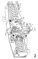
- the constant support 1 for the shifting load in particular for a pipeline and not shown here, has a fastening part 2, a load bearing part 3 and arranged between the fastening part 2 and load bearing part 3 spring system 4 for generating a t w of the load-bearing part 3 over a carrying path the attachment part 2 constant wearing force T on.
- the spring system 4 comprises a load-receiving suspension 5, a compensation device 6 for compensating for changing spring forces of the suspension 5 via the carrying path t w and a biasing device 7 for setting a biasing spring force V of the suspension 5.
- the fastening part 2 has a housing 8 with plate-like side walls 9, of which the respective front side wall in the FIGS. 1 . 2 . 3a-c and 7a-c as well as the lid-like upper left side walls in the FIGS. 1 . 2 . 7a and 7b have been omitted. Both larger side walls, ie the front side wall and the rear side wall 9, are connected to an upper connecting lug 10, which has a fastening opening 8 for connection and suspension to a base, not shown here.
- the housing 8 encloses the spring system laterally upwards 4 and the load-bearing part 3, the load-bearing part 3 being slidable backwards through the support path t w in a direction of displacement v in the direction of a load force L downwards through an aperture 12 out of the housing 8 and back against the direction of displacement v in the direction of the carrying force T.
- a correction device 13 is provided for correcting deviations of the carrying force T via the carrying path t w as a result of a changed biasing spring force V.
- the correction device 13 as explained in more detail below, simultaneously provided with a biasing function for the suspension 5.
- the correction device 13 is coupled to a part of the pretensioning device 7 in order to be able to carry out the correction via the correction device 13 at the same time in one work step and automatically with a change of, for example, factory setting of the pretensioning spring force.
- the suspension 5 comprises two springs 14 arranged horizontally in the installed position and designed as compression springs, which are each supported with a force side on the housing 8 and with a load side in a load point 15 on the compensation device 6.
- the compensating device 6 has, for each spring 14, two cam levers 16, which are spaced parallel to one another and aligned perpendicular to the carrying force T and freely pivotable on the housing 8 on a common pivot pin 17 about a pivot axis s.
- the pivot axis s is perpendicular to the front and rear side wall 9 of the housing 8.
- On the pivot pin 17 mounted sleeves 22 spaced the cam lever 16 from each other and from the side walls.
- the springs 14 engage with their respective load point 15 to form a force arm K at their associated cam levers 16.
- the cam lever 16 are each provided with a cam side surface 18, which have a specific curved course to compensate for changing spring forces on the support path t w .
- the Load bearing part 3 has load rollers 19, which are arranged rotatable about a common axis of rotation d perpendicular to the spring axis f and perpendicular to the direction of the load force t.
- the load-bearing part 3 rests on the cam side surfaces 18 via the load rollers 19.
- the load rollers 19 are in each case in a roll-off point 24 on their respective associated cam side surface 18, wherein the roll-off point 24 is at each point of the cam side surface 18 spaced from the axis of rotation d.
- a load arm L forms between the unwinding point 23 and the pivot axis s, which can be changed by rolling the load roller 19 over the curved side surface 18.
- This is in Figure 7a to c shown. It is conspicuous that the cam side surfaces 18, as on the front cam lever 16 in FIG Fig. 1 can be seen over their entire non-linear, curved, and steady course necessary always with a directional components in the direction of supply direction t to produce the carrying force T in the direction of load force t for the load. Since in operation, the carrying force T with the load force L k is to be in equilibrium, the load bearing member 3, after the suspension 5 has been factory set to a certain bias, blocked.
- the cam lever 16 assigned to the right-hand spring 14 in the figures surround laterally two load carrying lugs 20 which are attached to the axis of rotation d and guided parallel down through the diaphragm 12 for connection to a further carrying element 21 for suspending the load, not shown here.
- the left-hand spring 14 associated cam lever 16 are arranged between the spaced load bearing lugs 20 out.
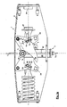
- the two springs 14 are in the in Fig. 1 . 2 . 3a and 7a-c shown basic position on a common, horizontal spring axis f arranged.
- the constant support 1 with respect to a mirror symmetry plane which is perpendicular to the rear side wall 9 of the housing 8 and perpendicular to a extending in the direction of force and extending parallel to the spring axes plane, a mirror-symmetrical course of forces and a largely mirror-symmetrical Arrangement of the components.
- the correction device 13 is arranged in the housing 8.
- a guide 25 in the form of a slot 26 which is integrated in the cam levers 16 respectively.
- the slot 26 each have a load point 15 of the spring 14 is displaceably guided over a guide path f w , wherein the guide path f w is limited by the fact that the load point 15 in the direction of the longitudinal axis 1 ends in the slot 26 abuts.
- the indicated in the drawing guide path f w refers to a geometric center of the load point 15 in the longitudinal axis 1 of the elongated hole 26.
- the slot 26 is arranged with its longitudinal axis 1 inclined to the carrying force direction t and in a path component in the direction of the spring axis f.
- a distance between the load point 15 and the pivot axis s forms a force arm K, which can be changed by moving the load point 15 in the guide 25 or in the slot 26 via the guide path f w .
- the correction of adjusting the change in the bias deviation from the desired constant course of the carrying force T via the carrying path t w by means of a change of the power lever K with respect to its length and its direction relative to the cam lever associated therewith.
- the correction it is possible to detect, for example, changed friction losses in the moving parts and in particular in the parts which slide off or roll off relative to one another.
- the front left cam lever 16 omitted or indicated in the form of a dashed and transparent drawn phantom image.
- the springs 14 are supported on the load side in each case against a plate-like load abutment 27, which in turn is supported pivotably on a transverse pin 28.
- the transverse pin 28 is slidably mounted in the elongated holes 26 with both ends formed as guide ends 29.
- the leaders 29 are each of two sides ago and each flattened laterally to form a shoulder 30 and two parallel guide side surfaces 31.
- a mark 32 is provided in the form of a notch with a V-shaped cross section, which is perpendicular to the guide side surfaces 31 and perpendicular to the longitudinal axis 1 and indicates an end center with respect to the longitudinal axis 1 of the elongated hole 26.
- a load scale 33 for displaying the guiding path f w of the leading end 29 disposed in the hole hole 26
- the load scale is 33 in kilo-Newtons (kN) and scaled in pounds (LPS).
- the transverse pin 28 is determined by means of a below with reference to FIGS. 5 and 6 closer holding device 34 held in the slot 26 in a certain correction position and moved over the guide path f w .
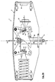
- FIGS. 3a to 3c Based on FIGS. 3a to 3c the principle underlying the correction device 13 will be explained in more detail.
- the right spring is omitted.
- the position of the load point 15 of the left spring 14 remains unchanged in the home position to make the change in position of the load point 15 of the omitted right spring due to a changed presetting of the bias clear. Incidentally, this would scarcely be carried out in practice, since symmetrical force ratios are always sought and a same preload would be set on both springs.
- the cam lever 16 itself remain in the FIGS. 3a-c unchanged in their position, so that the respective distance between the pivot axis s and the roll-off point 24 and thus the respective load arm L in all cam levers 16 is the same and unchanged remains.
- FIG. 3a are both load points 15 of the springs 14 in the basic position, while the right in the figures right load point 15 of the right spring 14 in FIG. 3b on the way f w down and in Figure 3c is displaced upward on the guide path f w up to the end of the elongated hole 26.
- the force components T s in the direction of delivery force t and T h are qualitatively plotted in the horizontal direction. Furthermore, qualitatively the biasing spring force V is shown, which changes according to the displacement of the load point 15 in the slot 26.
- the force component T s changes proportionally with changing biasing spring force V, wherein the biasing spring force V is changed due to a displacement of the spring 14 from its horizontal position in the basic position also in their direction. Due to the prevailing balance of forces and the use of four cam levers 16, the single force component T s on a load roller 19 is one quarter of the total carrying force T, if other influences such as changed friction on moving parts are not taken into account.
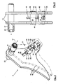
- the biasing device 7 further comprises an adjusting device 35 for presetting the biasing force.
- an adjusting device 35 for presetting the biasing force.
- the adjustment device 35 is constructed more inexpensively.
- the spring 14 is mounted on the mounting side each in a mounting abutment 36 which is displaceable and lockable in the direction of the spring axis (f).
- the spring 14 is mounted on the mounting side each in a mounting abutment 36 which is displaceable and lockable in the direction of the spring axis (f).
- the spring 14 is mounted on the mounting side each in a mounting abutment 36 which is displaceable and lockable in the direction of the spring axis (f).
- a clamping wall 37 side wall 9 of the housing 8 on which the spring 14 is supported on the mounting side, in the direction of the spring axis (f) and relative to the front or rear side wall 9 slidably disposed and fixed in a certain bias position.
- the adjustment device 35 has, for each spring 14, two transverse struts 38 with a rectangular cross-section, which are arranged perpendicular to the spring axis f and anchored on the front side in the front and rear side wall 9, respectively.
- the clamping wall 37 lead two diagonally arranged in the clamping wall 39 to the cross braces 38 and are each guided by a through hole 40 with internal thread, in which the clamping screws 39 engage respectively. With a rotation of the clamping screws 39 thus the clamping wall 37 is shifted and changed the bias of the springs 14.
- a lock nut 41 is provided, which is guided for countering in a specific biasing position against the transverse struts 38.
- the pretensioning of the springs 14 is pretensioned via the adjusting device 35 on the factory side or on the workshop side and then fixed in the specific pretensioning device and possibly sealed.
- the load point 15 is in the basic position, in which the load point 15 is held in the middle of the elongated hole 26.
- the same can be adapted via the correction device 13 of the actually existing load.
- the holding device 3 is based on the FIGS. 5 and 6 , each showing a pair of parallel cam lever 16, the transverse bolt 28, the pivot pin 17 together with sleeves 23 and the holding device 34 in a perspective top view and in a bottom view, explained in more detail.
- FIG. 5 front cam lever 16 shown for clarity as a phantom image.
- a transverse block 42 is provided with a rectangular cross-section parallel to the transverse pin 28.
- the transverse block 42 is parallel and spaced on the longitudinal axis 1 of the elongated hole 26 and the end between the cam levers 16 and with the same via a plug connection loosely connected rotationally connected, wherein it passes through the pivot lever 16 end and surmounted by a small amount.
- the transverse pin 28 has a circular cross-section except for its flattened leading ends 29. The leading ends 29 are due to the connector of cross bolt 28 and a cross block 42 with associated cam levers 16, these are easy to assemble and disassemble.
- Cross pin 28 is connected via a centrally in the transverse block 28 rotatably mounted spindle 43 with the transverse block 42 and linearly displaceable in the slot 26 via rotation of the spindle 43.
- the transverse pin 28 has a central first passage opening 44 with a thread not explicitly shown here, in which the spindle 43 engages. With rotation of the spindle 43, the transverse pin 28 mounted in the elongated holes 26 with its guide ends 29 can thus be displaced linearly in the longitudinal extent of the oblong holes 26.
- the transverse block 42 has a second passage opening 45, in which the spindle 43 is rotatably mounted.
- the transverse block 42 is disposed below the transverse pin 28.
- the spindle 43 projects through with a Einstellende 47, the cross block 42, wherein the Einstellende 47 is frontally provided with a screw head 48 which is easily accessible from below.
- the change in the bias of the suspension 4 by means of a rotation of the screw head 48 and the spindle 43 can be made in particular when, as usual and provided in this embodiment, no housing bottom is provided.
- leading end 29 extends through the slot 26 and projects beyond the side wall 9, in which the slot 26 is recessed, by a small amount.
- a partial section through the pivot pin 17 FIG. 6 is clearly removable, that the sleeves 23 are pushed onto the pivot pin 17 and the end face the cam levers 16 for spacing them from each other and the housing 8.
- the axis of rotation d is designed as a load roller axle 49, on which all four load rollers 19 are arranged together, which in turn are spaced apart by sleeves 23 and by the attached support tabs 20 from each other and from the housing walls 9.
- the load roller axle 49 is arranged with its two ends in each case in the vertical guide slot 22 of the front and the rear side wall 9 of the housing 8, wherein the guide slot 22 only in FIG. 8 Also shown in the front side wall 9 of the housing 8.
- FIGS. 7a to 7c 3 shows the displacement of the load-bearing member 3 via the carrying path t w is shown in three displacement positions.
- the load-carrying part 3 is shown in an upper displacement position in which it is maximally drawn into the housing 8.
- FIG. 7b is the load supporting part 3 in a middle displacement position and in FIG. 7c shown in a lower displacement position in which the load supporting part 3 is pulled out of the housing 8 maximum.
- the springs 14 are easily pivoted.
- the geometries of the constant carrier 1 are in this case adjusted so that the springs 14 of the middle displacement position are almost perpendicular to the direction of displacement v. Further, the biasing spring force V set via the correction device 13 remains constant.
- the cam side surfaces 13 are profiled such that the force component T s increases continuously and non-linearly from the lower shift position to the upper shift position to a calculated extent such that the changing spring forces of the springs 14 upon compression and separation thereof, and through the above said pivoting of the springs 14 with pivoting of the cam lever 16 changed direction of the spring axis f is fully compensated and acting on the wear path t w constant carrying force T on the load.
- the carrying force T is qualitatively approximately the sum of all vertical force components T s on the load rollers 19. Since four pivot levers 16 are provided here, which act on assigned load rollers 19, the carrying force T is four times the force components T s . In the FIGS.
- FIG. 8 shows the constant beam 1 as in FIG. 1 in a perspective side view, but here the missing side walls 9 of the housing 8 are completed.
- two housing windows 50 are incorporated for viewing the slot 26 and the load scale 33 in height thereof.
- a path scale 54 is provided for displaying the carrying path t w , which is scaled in units cm and mm as well as in inches.
- the load bearing axle 49 and the pivot pins each extend at the end 17 through the front and rear side wall 9 and are secured by retaining rings 55 against axial displacement or falling out.
- the side walls 9 of the housing 8, the terminal lug 10 and the aperture 12 are, as not explicitly shown here, screwed together, while arranged in the housing 8 components with respect to the compensation device 6, the correction device 13 and the load rollers 19 and the load carrying tabs 20 are loosely arranged so that the constant carrier can be assembled and disassembled inexpensively.
Landscapes
- Engineering & Computer Science (AREA)
- General Engineering & Computer Science (AREA)
- Mechanical Engineering (AREA)
- Springs (AREA)
- Transmission Devices (AREA)
- Supports For Pipes And Cables (AREA)
- Insulated Conductors (AREA)
- Apparatus For Radiation Diagnosis (AREA)
- Closing And Opening Devices For Wings, And Checks For Wings (AREA)
- Vibration Prevention Devices (AREA)
- Support Of The Bearing (AREA)
- Separation Using Semi-Permeable Membranes (AREA)
- Transition And Organic Metals Composition Catalysts For Addition Polymerization (AREA)
- Preparing Plates And Mask In Photomechanical Process (AREA)
Applications Claiming Priority (2)
| Application Number | Priority Date | Filing Date | Title |
|---|---|---|---|
| DE102006062195A DE102006062195B3 (de) | 2006-12-22 | 2006-12-22 | Konstantträger |
| PCT/EP2007/063923 WO2008077815A1 (de) | 2006-12-22 | 2007-12-14 | Konstantträger |
Publications (2)
| Publication Number | Publication Date |
|---|---|
| EP2106513A1 EP2106513A1 (de) | 2009-10-07 |
| EP2106513B1 true EP2106513B1 (de) | 2011-04-20 |
Family
ID=39186124
Family Applications (1)
| Application Number | Title | Priority Date | Filing Date |
|---|---|---|---|
| EP07866284A Active EP2106513B1 (de) | 2006-12-22 | 2007-12-14 | Konstantträger |
Country Status (12)
| Country | Link |
|---|---|
| US (1) | US8251338B2 (enExample) |
| EP (1) | EP2106513B1 (enExample) |
| JP (1) | JP5415958B2 (enExample) |
| KR (1) | KR101323428B1 (enExample) |
| CN (1) | CN101652594B (enExample) |
| AT (1) | ATE506570T1 (enExample) |
| AU (1) | AU2007338120B2 (enExample) |
| DE (2) | DE102006062195B3 (enExample) |
| ES (1) | ES2365369T3 (enExample) |
| RU (1) | RU2434174C2 (enExample) |
| WO (1) | WO2008077815A1 (enExample) |
| ZA (1) | ZA200904616B (enExample) |
Families Citing this family (20)
| Publication number | Priority date | Publication date | Assignee | Title |
|---|---|---|---|---|
| RU2444667C1 (ru) * | 2010-06-25 | 2012-03-10 | Закрытое акционерное общество "Энергомаш (Белгород) - БЗЭМ" | Подвеска постоянного усилия |
| US9757129B2 (en) * | 2013-07-08 | 2017-09-12 | Covidien Lp | Coupling member configured for use with surgical devices |
| CN104565701B (zh) * | 2013-10-11 | 2018-02-23 | 佳能精技立志凯株式会社 | 负载支承机构 |
| CN103574170B (zh) * | 2013-11-12 | 2015-09-09 | 成都科盛石油科技有限公司 | 一种可调式管道支架 |
| DE102015218851A1 (de) * | 2015-09-30 | 2017-03-30 | Siemens Aktiengesellschaft | Federaggregat, Federspeicher und Aktor |
| CN105526426A (zh) * | 2015-12-25 | 2016-04-27 | 北方华锦化学工业集团有限公司 | 上猪尾管吊装系统 |
| CN106764089A (zh) * | 2017-03-14 | 2017-05-31 | 扬州市泰克管道机械有限公司 | 一种双簧平衡式恒力支吊架 |
| CN107453313A (zh) * | 2017-07-25 | 2017-12-08 | 国网山东省电力公司龙口市供电公司 | 一种电力电缆分类连接装置 |
| CN108386616B (zh) * | 2018-03-06 | 2020-02-07 | 西安热工研究院有限公司 | 一种适用于空间高度受限的紧凑型恒力支架 |
| CN108709018A (zh) * | 2018-07-23 | 2018-10-26 | 扬州市泰克管道机械有限公司 | 一种紧凑型恒力支吊架 |
| CN108953769A (zh) * | 2018-09-27 | 2018-12-07 | 常州市武进武南管道设备有限公司 | 恒力弹簧支吊架 |
| CN110410443B (zh) * | 2019-08-05 | 2020-08-14 | 北京航空航天大学 | 一种零刚度冲击隔离装置 |
| CN110737953A (zh) * | 2019-09-29 | 2020-01-31 | 山东理工大学 | 基于力平衡的紧凑型恒力弹簧支吊架凸轮曲线设计方法 |
| CN110657286A (zh) * | 2019-11-08 | 2020-01-07 | 常州市武进武南管道设备有限公司 | 双簧铰接恒力弹簧支吊架 |
| DE102020116261A1 (de) * | 2020-06-19 | 2021-12-23 | Lisega SE | Positionsanzeigevorrichtung für ein Tragelement |
| RU2753088C1 (ru) * | 2020-07-31 | 2021-08-11 | Публичное акционерное общество "ОНХП" | Подвеска постоянного усилия |
| RU2759882C1 (ru) * | 2020-12-14 | 2021-11-18 | Федеральное государственное бюджетное образовательное учреждение высшего образования "Ярославский государственный технический университет" ФГБОУВО "ЯГТУ" | Подвеска постоянного усилия |
| CN112756431B (zh) * | 2021-02-04 | 2023-05-09 | 安徽钰鹏矿山机电设备有限公司 | 一种用于液压支柱内筒的校直装置 |
| RU2759884C1 (ru) * | 2021-02-25 | 2021-11-18 | Федеральное государственное бюджетное образовательное учреждение высшего образования "Ярославский государственный технический университет" ФГБОУВО "ЯГТУ" | Опора постоянного усилия |
| CN113919087B (zh) * | 2021-09-09 | 2024-08-20 | 华电电力科学研究院有限公司 | 适用于变载荷管道的主辅簧式恒力吊架凸轮曲线设计方法 |
Family Cites Families (17)
| Publication number | Priority date | Publication date | Assignee | Title |
|---|---|---|---|---|
| US2395730A (en) * | 1944-07-20 | 1946-02-26 | American Locomotive Co | Constant load-supporting device |
| US2924411A (en) * | 1955-05-19 | 1960-02-09 | Grinnell Corp | Counterbalancing mechanism |
| DE1901725A1 (de) | 1968-01-16 | 1969-09-04 | British Ind Engineering Compan | Aufhaengevorrichtung fuer Rohre od.dgl. |
| GB1242140A (en) | 1968-12-20 | 1971-08-11 | British Ind Engineering Compan | Constant tension supports suitable for pipes |
| FR2286330A1 (fr) * | 1974-09-24 | 1976-04-23 | Aquitaine Chaudronneries Tuyau | Dispositif equilibreur de charge a reaction constante ou sensiblement constante |
| DE7617092U1 (de) * | 1976-05-28 | 1977-08-18 | Lisega Kraftwerkstechnik Gmbh & Co Kg, 2148 Zeven | Aufhängevorrichtung für sich verschiebende Lasten, insbesondere Rohrleitungen u.dgl |
| SU850965A1 (ru) * | 1979-12-21 | 1981-07-30 | Алма-Атинское Отделение Государственногопроектного Института "Сантехпроект"Госстроя Cccp | Опора трубопровода |
| DE3501853A1 (de) * | 1985-01-22 | 1986-07-24 | Lisega Kraftwerkstechnik GmbH, 2730 Zeven | Aufhaengevorrichtung fuer sich verschiebende lasten, insbesondere rohrleitungen u.dgl. |
| ES2022536B3 (es) * | 1987-07-14 | 1991-12-01 | Siemens Ag | Procedimiento y dispositivo para comprobacion de funcion de un dispositivo de suspension o suspension para una carga |
| EP0306786B1 (de) * | 1987-09-08 | 1991-01-30 | IWK Regler und Kompensatoren GmbH | Konstanthänger |
| DE8806433U1 (de) * | 1988-05-17 | 1989-09-14 | Lisega Kraftwerkstechnik GmbH, 2730 Zeven | Aufhängevorrichtung für sich verschiebende Lasten, insbesondere Rohrleitungen u. dgl. |
| DE3816673A1 (de) * | 1988-05-17 | 1989-11-30 | Lisega Kraftwerktech Gmbh | Aufhaengevorrichtung fuer sich verschiebende lasten, insbesondere rohrleitungen u. dgl. |
| JPH06258580A (ja) * | 1993-03-03 | 1994-09-16 | Olympus Optical Co Ltd | 手術用顕微鏡支持装置 |
| DE10104661B4 (de) | 2001-02-02 | 2004-03-11 | Bruno Pischzik | Aufhängevorrichtung für sich in vertikaler Richtung verschiebende Lasten, insbesondere Rohrleitungen und dergleichen |
| CN2451855Y (zh) * | 2000-11-30 | 2001-10-03 | 国家电力公司郑州机械设计研究所 | 恒力支吊架 |
| CN2814073Y (zh) * | 2005-09-13 | 2006-09-06 | 江阴市石油化工设备有限公司 | 无侧偏移恒力弹簧支座 |
| DE102005045736B4 (de) * | 2005-09-23 | 2008-12-11 | Lisega Ag | Konstantträger |
-
2006
- 2006-12-22 DE DE102006062195A patent/DE102006062195B3/de active Active
-
2007
- 2007-12-14 ES ES07866284T patent/ES2365369T3/es active Active
- 2007-12-14 AU AU2007338120A patent/AU2007338120B2/en active Active
- 2007-12-14 WO PCT/EP2007/063923 patent/WO2008077815A1/de not_active Ceased
- 2007-12-14 RU RU2009128208/06A patent/RU2434174C2/ru active
- 2007-12-14 DE DE502007007028T patent/DE502007007028D1/de active Active
- 2007-12-14 AT AT07866284T patent/ATE506570T1/de active
- 2007-12-14 CN CN2007800506844A patent/CN101652594B/zh active Active
- 2007-12-14 EP EP07866284A patent/EP2106513B1/de active Active
- 2007-12-14 US US12/520,832 patent/US8251338B2/en active Active
- 2007-12-14 JP JP2009542009A patent/JP5415958B2/ja active Active
- 2007-12-14 ZA ZA200904616A patent/ZA200904616B/xx unknown
- 2007-12-14 KR KR1020097015316A patent/KR101323428B1/ko active Active
Also Published As
| Publication number | Publication date |
|---|---|
| AU2007338120A1 (en) | 2008-07-03 |
| ATE506570T1 (de) | 2011-05-15 |
| KR101323428B1 (ko) | 2013-10-29 |
| JP2010513814A (ja) | 2010-04-30 |
| US20100108852A1 (en) | 2010-05-06 |
| RU2009128208A (ru) | 2011-01-27 |
| US8251338B2 (en) | 2012-08-28 |
| ES2365369T3 (es) | 2011-09-30 |
| WO2008077815A1 (de) | 2008-07-03 |
| RU2434174C2 (ru) | 2011-11-20 |
| ZA200904616B (en) | 2010-09-29 |
| AU2007338120B2 (en) | 2012-12-06 |
| DE102006062195B3 (de) | 2008-04-30 |
| CN101652594A (zh) | 2010-02-17 |
| DE502007007028D1 (de) | 2011-06-01 |
| JP5415958B2 (ja) | 2014-02-12 |
| CN101652594B (zh) | 2011-08-10 |
| KR20100014327A (ko) | 2010-02-10 |
| EP2106513A1 (de) | 2009-10-07 |
Similar Documents
| Publication | Publication Date | Title |
|---|---|---|
| EP2106513B1 (de) | Konstantträger | |
| EP1929191B1 (de) | Konstantträger | |
| DE68906457T2 (de) | Aufhängungseinrichtung mit einem Nockenunterstützungselement. | |
| EP3885518A1 (de) | Stellarmantrieb | |
| WO2020151889A1 (de) | Pedelec-tretlagerantriebseinheit | |
| EP3610541A1 (de) | Zugentlastung zur schnellmontage für eine energieführungskette | |
| DE202009016353U1 (de) | Traganordnung für eine Solaranlage | |
| EP0611724A1 (de) | Führungsvorrichtung für Aufzüge | |
| EP0964100A2 (de) | Rolleneinrichtung für eine einer Backenschiene zugeordneten Zunge einer Weiche | |
| DE102013108807B4 (de) | Befestigungsvorrichtung für Fahrzeugeinrichtungen | |
| DE102010004771B3 (de) | Türband für Aluminiumtüren | |
| EP1810791A2 (de) | Vorrichtung zum Spannen einer Schraubenfeder eines Federdämpferbeines | |
| EP1507095A2 (de) | Vorrichtung zur kontrollierten Lagerung von Bauteilen auf Schwingungsdämpfern | |
| DE20020900U1 (de) | Gardinenstange | |
| EP0753610B1 (de) | Wanderdeckelkarde | |
| DE102017121641A1 (de) | Riemenspanner für Längsförderer | |
| DE19507339C2 (de) | Abgefederter Fahrzeugsitz | |
| DE102015010990B4 (de) | Aufhänge- oder Abstützvorrichtung für sich in vertikaler Richtung verschiebende Lasten, insbesondere Rohrleitungen und dergleichen | |
| DE102004062764A1 (de) | Rollenwagen | |
| DE4009528A1 (de) | Verbaueinrichtung fuer den grabenverbau | |
| WO2002008651A1 (de) | Aufhängevorrichtung | |
| DE102017124816A1 (de) | Halterung für Anzeigevorrichtung | |
| DE29617978U1 (de) | Halterung zum Lagern einer Rohrleitung | |
| EP3421705B1 (de) | Kompensationshilfe für schiebetüren | |
| DE102016222880A1 (de) | Vorrichtung und Verfahren zum Unterstützen eines Umstellens einer Weiche |
Legal Events
| Date | Code | Title | Description |
|---|---|---|---|
| PUAI | Public reference made under article 153(3) epc to a published international application that has entered the european phase |
Free format text: ORIGINAL CODE: 0009012 |
|
| 17P | Request for examination filed |
Effective date: 20090713 |
|
| AK | Designated contracting states |
Kind code of ref document: A1 Designated state(s): AT BE BG CH CY CZ DE DK EE ES FI FR GB GR HU IE IS IT LI LT LU LV MC MT NL PL PT RO SE SI SK TR |
|
| DAX | Request for extension of the european patent (deleted) | ||
| GRAP | Despatch of communication of intention to grant a patent |
Free format text: ORIGINAL CODE: EPIDOSNIGR1 |
|
| RTI1 | Title (correction) |
Free format text: SUSPENSION WITH CONSTANT FORCE |
|
| GRAS | Grant fee paid |
Free format text: ORIGINAL CODE: EPIDOSNIGR3 |
|
| GRAA | (expected) grant |
Free format text: ORIGINAL CODE: 0009210 |
|
| AK | Designated contracting states |
Kind code of ref document: B1 Designated state(s): AT BE BG CH CY CZ DE DK EE ES FI FR GB GR HU IE IS IT LI LT LU LV MC MT NL PL PT RO SE SI SK TR |
|
| REG | Reference to a national code |
Ref country code: GB Ref legal event code: FG4D Free format text: NOT ENGLISH |
|
| REG | Reference to a national code |
Ref country code: CH Ref legal event code: EP |
|
| REG | Reference to a national code |
Ref country code: IE Ref legal event code: FG4D Free format text: LANGUAGE OF EP DOCUMENT: GERMAN |
|
| REF | Corresponds to: |
Ref document number: 502007007028 Country of ref document: DE Date of ref document: 20110601 Kind code of ref document: P |
|
| REG | Reference to a national code |
Ref country code: DE Ref legal event code: R096 Ref document number: 502007007028 Country of ref document: DE Effective date: 20110601 |
|
| REG | Reference to a national code |
Ref country code: NL Ref legal event code: T3 |
|
| REG | Reference to a national code |
Ref country code: DE Ref legal event code: R082 Ref document number: 502007007028 Country of ref document: DE Representative=s name: PATENTANWAELTE LIPPERT, STACHOW & PARTNER, DE |
|
| LTIE | Lt: invalidation of european patent or patent extension |
Effective date: 20110420 |
|
| REG | Reference to a national code |
Ref country code: ES Ref legal event code: FG2A Ref document number: 2365369 Country of ref document: ES Kind code of ref document: T3 Effective date: 20110930 |
|
| PG25 | Lapsed in a contracting state [announced via postgrant information from national office to epo] |
Ref country code: SE Free format text: LAPSE BECAUSE OF FAILURE TO SUBMIT A TRANSLATION OF THE DESCRIPTION OR TO PAY THE FEE WITHIN THE PRESCRIBED TIME-LIMIT Effective date: 20110420 Ref country code: PT Free format text: LAPSE BECAUSE OF FAILURE TO SUBMIT A TRANSLATION OF THE DESCRIPTION OR TO PAY THE FEE WITHIN THE PRESCRIBED TIME-LIMIT Effective date: 20110822 Ref country code: LT Free format text: LAPSE BECAUSE OF FAILURE TO SUBMIT A TRANSLATION OF THE DESCRIPTION OR TO PAY THE FEE WITHIN THE PRESCRIBED TIME-LIMIT Effective date: 20110420 |
|
| REG | Reference to a national code |
Ref country code: DE Ref legal event code: R081 Ref document number: 502007007028 Country of ref document: DE Owner name: LISEGA SE, DE Free format text: FORMER OWNER: LISEGA AG, 27404 ZEVEN, DE Effective date: 20110923 Ref country code: DE Ref legal event code: R082 Ref document number: 502007007028 Country of ref document: DE Representative=s name: PATENTANWAELTE LIPPERT, STACHOW & PARTNER, DE Effective date: 20110923 Ref country code: DE Ref legal event code: R082 Ref document number: 502007007028 Country of ref document: DE Representative=s name: LIPPERT STACHOW PATENTANWAELTE RECHTSANWAELTE , DE Effective date: 20110923 |
|
| REG | Reference to a national code |
Ref country code: IE Ref legal event code: FD4D |
|
| PG25 | Lapsed in a contracting state [announced via postgrant information from national office to epo] |
Ref country code: CY Free format text: LAPSE BECAUSE OF FAILURE TO SUBMIT A TRANSLATION OF THE DESCRIPTION OR TO PAY THE FEE WITHIN THE PRESCRIBED TIME-LIMIT Effective date: 20110420 Ref country code: IS Free format text: LAPSE BECAUSE OF FAILURE TO SUBMIT A TRANSLATION OF THE DESCRIPTION OR TO PAY THE FEE WITHIN THE PRESCRIBED TIME-LIMIT Effective date: 20110820 Ref country code: LV Free format text: LAPSE BECAUSE OF FAILURE TO SUBMIT A TRANSLATION OF THE DESCRIPTION OR TO PAY THE FEE WITHIN THE PRESCRIBED TIME-LIMIT Effective date: 20110420 Ref country code: SI Free format text: LAPSE BECAUSE OF FAILURE TO SUBMIT A TRANSLATION OF THE DESCRIPTION OR TO PAY THE FEE WITHIN THE PRESCRIBED TIME-LIMIT Effective date: 20110420 Ref country code: GR Free format text: LAPSE BECAUSE OF FAILURE TO SUBMIT A TRANSLATION OF THE DESCRIPTION OR TO PAY THE FEE WITHIN THE PRESCRIBED TIME-LIMIT Effective date: 20110721 Ref country code: FI Free format text: LAPSE BECAUSE OF FAILURE TO SUBMIT A TRANSLATION OF THE DESCRIPTION OR TO PAY THE FEE WITHIN THE PRESCRIBED TIME-LIMIT Effective date: 20110420 |
|
| PG25 | Lapsed in a contracting state [announced via postgrant information from national office to epo] |
Ref country code: EE Free format text: LAPSE BECAUSE OF FAILURE TO SUBMIT A TRANSLATION OF THE DESCRIPTION OR TO PAY THE FEE WITHIN THE PRESCRIBED TIME-LIMIT Effective date: 20110420 Ref country code: IE Free format text: LAPSE BECAUSE OF FAILURE TO SUBMIT A TRANSLATION OF THE DESCRIPTION OR TO PAY THE FEE WITHIN THE PRESCRIBED TIME-LIMIT Effective date: 20110420 Ref country code: CZ Free format text: LAPSE BECAUSE OF FAILURE TO SUBMIT A TRANSLATION OF THE DESCRIPTION OR TO PAY THE FEE WITHIN THE PRESCRIBED TIME-LIMIT Effective date: 20110420 |
|
| PLBE | No opposition filed within time limit |
Free format text: ORIGINAL CODE: 0009261 |
|
| STAA | Information on the status of an ep patent application or granted ep patent |
Free format text: STATUS: NO OPPOSITION FILED WITHIN TIME LIMIT |
|
| PG25 | Lapsed in a contracting state [announced via postgrant information from national office to epo] |
Ref country code: RO Free format text: LAPSE BECAUSE OF FAILURE TO SUBMIT A TRANSLATION OF THE DESCRIPTION OR TO PAY THE FEE WITHIN THE PRESCRIBED TIME-LIMIT Effective date: 20110420 Ref country code: PL Free format text: LAPSE BECAUSE OF FAILURE TO SUBMIT A TRANSLATION OF THE DESCRIPTION OR TO PAY THE FEE WITHIN THE PRESCRIBED TIME-LIMIT Effective date: 20110420 Ref country code: SK Free format text: LAPSE BECAUSE OF FAILURE TO SUBMIT A TRANSLATION OF THE DESCRIPTION OR TO PAY THE FEE WITHIN THE PRESCRIBED TIME-LIMIT Effective date: 20110420 Ref country code: DK Free format text: LAPSE BECAUSE OF FAILURE TO SUBMIT A TRANSLATION OF THE DESCRIPTION OR TO PAY THE FEE WITHIN THE PRESCRIBED TIME-LIMIT Effective date: 20110420 |
|
| 26N | No opposition filed |
Effective date: 20120123 |
|
| REG | Reference to a national code |
Ref country code: DE Ref legal event code: R097 Ref document number: 502007007028 Country of ref document: DE Effective date: 20120123 |
|
| PG25 | Lapsed in a contracting state [announced via postgrant information from national office to epo] |
Ref country code: MC Free format text: LAPSE BECAUSE OF NON-PAYMENT OF DUE FEES Effective date: 20111231 |
|
| REG | Reference to a national code |
Ref country code: CH Ref legal event code: PL |
|
| PG25 | Lapsed in a contracting state [announced via postgrant information from national office to epo] |
Ref country code: CH Free format text: LAPSE BECAUSE OF NON-PAYMENT OF DUE FEES Effective date: 20111231 Ref country code: LI Free format text: LAPSE BECAUSE OF NON-PAYMENT OF DUE FEES Effective date: 20111231 |
|
| PG25 | Lapsed in a contracting state [announced via postgrant information from national office to epo] |
Ref country code: MT Free format text: LAPSE BECAUSE OF FAILURE TO SUBMIT A TRANSLATION OF THE DESCRIPTION OR TO PAY THE FEE WITHIN THE PRESCRIBED TIME-LIMIT Effective date: 20110420 |
|
| PG25 | Lapsed in a contracting state [announced via postgrant information from national office to epo] |
Ref country code: LU Free format text: LAPSE BECAUSE OF NON-PAYMENT OF DUE FEES Effective date: 20111214 |
|
| PG25 | Lapsed in a contracting state [announced via postgrant information from national office to epo] |
Ref country code: BG Free format text: LAPSE BECAUSE OF FAILURE TO SUBMIT A TRANSLATION OF THE DESCRIPTION OR TO PAY THE FEE WITHIN THE PRESCRIBED TIME-LIMIT Effective date: 20110720 |
|
| PG25 | Lapsed in a contracting state [announced via postgrant information from national office to epo] |
Ref country code: TR Free format text: LAPSE BECAUSE OF FAILURE TO SUBMIT A TRANSLATION OF THE DESCRIPTION OR TO PAY THE FEE WITHIN THE PRESCRIBED TIME-LIMIT Effective date: 20110420 |
|
| PG25 | Lapsed in a contracting state [announced via postgrant information from national office to epo] |
Ref country code: HU Free format text: LAPSE BECAUSE OF FAILURE TO SUBMIT A TRANSLATION OF THE DESCRIPTION OR TO PAY THE FEE WITHIN THE PRESCRIBED TIME-LIMIT Effective date: 20110420 |
|
| REG | Reference to a national code |
Ref country code: AT Ref legal event code: MM01 Ref document number: 506570 Country of ref document: AT Kind code of ref document: T Effective date: 20121214 |
|
| PG25 | Lapsed in a contracting state [announced via postgrant information from national office to epo] |
Ref country code: AT Free format text: LAPSE BECAUSE OF NON-PAYMENT OF DUE FEES Effective date: 20121214 |
|
| REG | Reference to a national code |
Ref country code: FR Ref legal event code: PLFP Year of fee payment: 9 |
|
| REG | Reference to a national code |
Ref country code: FR Ref legal event code: PLFP Year of fee payment: 10 |
|
| REG | Reference to a national code |
Ref country code: FR Ref legal event code: PLFP Year of fee payment: 11 |
|
| PGFP | Annual fee paid to national office [announced via postgrant information from national office to epo] |
Ref country code: NL Payment date: 20241217 Year of fee payment: 18 Ref country code: BE Payment date: 20241216 Year of fee payment: 18 |
|
| PGFP | Annual fee paid to national office [announced via postgrant information from national office to epo] |
Ref country code: GB Payment date: 20241218 Year of fee payment: 18 |
|
| PGFP | Annual fee paid to national office [announced via postgrant information from national office to epo] |
Ref country code: FR Payment date: 20241218 Year of fee payment: 18 |
|
| PGFP | Annual fee paid to national office [announced via postgrant information from national office to epo] |
Ref country code: IT Payment date: 20241216 Year of fee payment: 18 |
|
| PGFP | Annual fee paid to national office [announced via postgrant information from national office to epo] |
Ref country code: DE Payment date: 20250224 Year of fee payment: 18 |
|
| PGFP | Annual fee paid to national office [announced via postgrant information from national office to epo] |
Ref country code: ES Payment date: 20250117 Year of fee payment: 18 |