EP2104478B1 - Tube à base de silicone pour transporter des matières malodorantes provenant du corps humain - Google Patents
Tube à base de silicone pour transporter des matières malodorantes provenant du corps humain Download PDFInfo
- Publication number
- EP2104478B1 EP2104478B1 EP07863463.1A EP07863463A EP2104478B1 EP 2104478 B1 EP2104478 B1 EP 2104478B1 EP 07863463 A EP07863463 A EP 07863463A EP 2104478 B1 EP2104478 B1 EP 2104478B1
- Authority
- EP
- European Patent Office
- Prior art keywords
- tube
- tubular
- silicone based
- silicone
- management assembly
- Prior art date
- Legal status (The legal status is an assumption and is not a legal conclusion. Google has not performed a legal analysis and makes no representation as to the accuracy of the status listed.)
- Active
Links
- 229920001296 polysiloxane Polymers 0.000 title claims abstract description 83
- 235000019645 odor Nutrition 0.000 claims abstract description 88
- 230000004888 barrier function Effects 0.000 claims abstract description 76
- 239000000463 material Substances 0.000 claims abstract description 48
- 239000010410 layer Substances 0.000 claims description 29
- -1 poly(vinylidene chloride) Polymers 0.000 claims description 27
- 229920000728 polyester Polymers 0.000 claims description 24
- 239000000853 adhesive Substances 0.000 claims description 18
- 230000001070 adhesive effect Effects 0.000 claims description 18
- 239000004952 Polyamide Substances 0.000 claims description 12
- 229920002647 polyamide Polymers 0.000 claims description 12
- 239000002210 silicon-based material Substances 0.000 claims description 12
- 229920000219 Ethylene vinyl alcohol Polymers 0.000 claims description 11
- 210000000664 rectum Anatomy 0.000 claims description 11
- 229920001328 Polyvinylidene chloride Polymers 0.000 claims description 10
- 230000005540 biological transmission Effects 0.000 claims description 10
- 239000007789 gas Substances 0.000 claims description 9
- 239000000203 mixture Substances 0.000 claims description 9
- 229920002635 polyurethane Polymers 0.000 claims description 8
- 239000004814 polyurethane Substances 0.000 claims description 8
- 229920002451 polyvinyl alcohol Polymers 0.000 claims description 8
- 229920002493 poly(chlorotrifluoroethylene) Polymers 0.000 claims description 7
- 239000005023 polychlorotrifluoroethylene (PCTFE) polymer Substances 0.000 claims description 7
- 239000004715 ethylene vinyl alcohol Substances 0.000 claims description 6
- QVGXLLKOCUKJST-UHFFFAOYSA-N atomic oxygen Chemical compound [O] QVGXLLKOCUKJST-UHFFFAOYSA-N 0.000 claims description 5
- 239000001301 oxygen Substances 0.000 claims description 5
- 229910052760 oxygen Inorganic materials 0.000 claims description 5
- 101000576320 Homo sapiens Max-binding protein MNT Proteins 0.000 claims description 4
- 239000004677 Nylon Substances 0.000 claims description 4
- 229920000571 Nylon 11 Polymers 0.000 claims description 4
- 229920000299 Nylon 12 Polymers 0.000 claims description 4
- 229920006121 Polyxylylene adipamide Polymers 0.000 claims description 4
- 229920006020 amorphous polyamide Polymers 0.000 claims description 4
- 229920006018 co-polyamide Polymers 0.000 claims description 4
- 229920001971 elastomer Polymers 0.000 claims description 4
- 239000000806 elastomer Substances 0.000 claims description 4
- 229920001778 nylon Polymers 0.000 claims description 4
- 229920003229 poly(methyl methacrylate) Polymers 0.000 claims description 4
- 229920002285 poly(styrene-co-acrylonitrile) Polymers 0.000 claims description 4
- 239000004926 polymethyl methacrylate Substances 0.000 claims description 4
- 239000004800 polyvinyl chloride Substances 0.000 claims description 4
- 229920003048 styrene butadiene rubber Polymers 0.000 claims description 4
- 239000012790 adhesive layer Substances 0.000 claims description 3
- 239000013464 silicone adhesive Substances 0.000 claims description 3
- 230000015572 biosynthetic process Effects 0.000 claims description 2
- 229920002631 room-temperature vulcanizate silicone Polymers 0.000 claims description 2
- XECAHXYUAAWDEL-UHFFFAOYSA-N acrylonitrile butadiene styrene Chemical compound C=CC=C.C=CC#N.C=CC1=CC=CC=C1 XECAHXYUAAWDEL-UHFFFAOYSA-N 0.000 claims 2
- 239000002648 laminated material Substances 0.000 claims 2
- 229920001897 terpolymer Polymers 0.000 claims 2
- 238000013007 heat curing Methods 0.000 claims 1
- 239000004590 silicone sealant Substances 0.000 claims 1
- 230000002550 fecal effect Effects 0.000 abstract description 10
- 239000010408 film Substances 0.000 description 27
- 238000000576 coating method Methods 0.000 description 14
- 239000011248 coating agent Substances 0.000 description 13
- 229920000052 poly(p-xylylene) Polymers 0.000 description 12
- 238000004519 manufacturing process Methods 0.000 description 8
- 241000234282 Allium Species 0.000 description 7
- 235000002732 Allium cepa var. cepa Nutrition 0.000 description 7
- 230000008878 coupling Effects 0.000 description 7
- 238000010168 coupling process Methods 0.000 description 7
- 238000005859 coupling reaction Methods 0.000 description 7
- 238000000034 method Methods 0.000 description 6
- 229920003023 plastic Polymers 0.000 description 6
- 239000004033 plastic Substances 0.000 description 6
- 238000001125 extrusion Methods 0.000 description 5
- 210000003608 fece Anatomy 0.000 description 5
- 229920002239 polyacrylonitrile Polymers 0.000 description 5
- 238000012360 testing method Methods 0.000 description 5
- 238000003855 Adhesive Lamination Methods 0.000 description 4
- 238000000151 deposition Methods 0.000 description 4
- 238000005336 cracking Methods 0.000 description 3
- 238000005137 deposition process Methods 0.000 description 3
- 238000007765 extrusion coating Methods 0.000 description 3
- 238000009501 film coating Methods 0.000 description 3
- 206010016766 flatulence Diseases 0.000 description 3
- 230000004048 modification Effects 0.000 description 3
- 238000012986 modification Methods 0.000 description 3
- 229920006284 nylon film Polymers 0.000 description 3
- 230000008569 process Effects 0.000 description 3
- 239000002344 surface layer Substances 0.000 description 3
- 239000010409 thin film Substances 0.000 description 3
- 238000003466 welding Methods 0.000 description 3
- 229920000122 acrylonitrile butadiene styrene Polymers 0.000 description 2
- 238000004873 anchoring Methods 0.000 description 2
- 229920000642 polymer Polymers 0.000 description 2
- 238000007789 sealing Methods 0.000 description 2
- 238000005452 bending Methods 0.000 description 1
- 230000000052 comparative effect Effects 0.000 description 1
- 150000001875 compounds Chemical class 0.000 description 1
- 230000001010 compromised effect Effects 0.000 description 1
- 229920001577 copolymer Polymers 0.000 description 1
- 230000001419 dependent effect Effects 0.000 description 1
- 210000002249 digestive system Anatomy 0.000 description 1
- 238000006073 displacement reaction Methods 0.000 description 1
- 238000005516 engineering process Methods 0.000 description 1
- 230000002708 enhancing effect Effects 0.000 description 1
- 239000005038 ethylene vinyl acetate Substances 0.000 description 1
- 230000003203 everyday effect Effects 0.000 description 1
- 239000012530 fluid Substances 0.000 description 1
- 229920002313 fluoropolymer Polymers 0.000 description 1
- 239000004811 fluoropolymer Substances 0.000 description 1
- 239000002654 heat shrinkable material Substances 0.000 description 1
- 229920001519 homopolymer Polymers 0.000 description 1
- 238000002347 injection Methods 0.000 description 1
- 239000007924 injection Substances 0.000 description 1
- 238000003780 insertion Methods 0.000 description 1
- 230000037431 insertion Effects 0.000 description 1
- 230000002262 irrigation Effects 0.000 description 1
- 238000003973 irrigation Methods 0.000 description 1
- 230000035699 permeability Effects 0.000 description 1
- 239000012466 permeate Substances 0.000 description 1
- 230000000379 polymerizing effect Effects 0.000 description 1
- 230000009467 reduction Effects 0.000 description 1
- 229920002379 silicone rubber Polymers 0.000 description 1
- 239000004945 silicone rubber Substances 0.000 description 1
- 239000002356 single layer Substances 0.000 description 1
- 230000005068 transpiration Effects 0.000 description 1
- 210000002700 urine Anatomy 0.000 description 1
- 238000013022 venting Methods 0.000 description 1
- 239000002699 waste material Substances 0.000 description 1
Images


Classifications
-
- B—PERFORMING OPERATIONS; TRANSPORTING
- B29—WORKING OF PLASTICS; WORKING OF SUBSTANCES IN A PLASTIC STATE IN GENERAL
- B29C—SHAPING OR JOINING OF PLASTICS; SHAPING OF MATERIAL IN A PLASTIC STATE, NOT OTHERWISE PROVIDED FOR; AFTER-TREATMENT OF THE SHAPED PRODUCTS, e.g. REPAIRING
- B29C63/00—Lining or sheathing, i.e. applying preformed layers or sheathings of plastics; Apparatus therefor
- B29C63/38—Lining or sheathing, i.e. applying preformed layers or sheathings of plastics; Apparatus therefor by liberation of internal stresses
- B29C63/42—Lining or sheathing, i.e. applying preformed layers or sheathings of plastics; Apparatus therefor by liberation of internal stresses using tubular layers or sheathings
-
- A—HUMAN NECESSITIES
- A61—MEDICAL OR VETERINARY SCIENCE; HYGIENE
- A61F—FILTERS IMPLANTABLE INTO BLOOD VESSELS; PROSTHESES; DEVICES PROVIDING PATENCY TO, OR PREVENTING COLLAPSING OF, TUBULAR STRUCTURES OF THE BODY, e.g. STENTS; ORTHOPAEDIC, NURSING OR CONTRACEPTIVE DEVICES; FOMENTATION; TREATMENT OR PROTECTION OF EYES OR EARS; BANDAGES, DRESSINGS OR ABSORBENT PADS; FIRST-AID KITS
- A61F5/00—Orthopaedic methods or devices for non-surgical treatment of bones or joints; Nursing devices; Anti-rape devices
- A61F5/44—Devices worn by the patient for reception of urine, faeces, catamenial or other discharge; Portable urination aids; Colostomy devices
- A61F5/445—Colostomy, ileostomy or urethrostomy devices
-
- B—PERFORMING OPERATIONS; TRANSPORTING
- B32—LAYERED PRODUCTS
- B32B—LAYERED PRODUCTS, i.e. PRODUCTS BUILT-UP OF STRATA OF FLAT OR NON-FLAT, e.g. CELLULAR OR HONEYCOMB, FORM
- B32B1/00—Layered products having a general shape other than plane
- B32B1/08—Tubular products
-
- B—PERFORMING OPERATIONS; TRANSPORTING
- B32—LAYERED PRODUCTS
- B32B—LAYERED PRODUCTS, i.e. PRODUCTS BUILT-UP OF STRATA OF FLAT OR NON-FLAT, e.g. CELLULAR OR HONEYCOMB, FORM
- B32B27/00—Layered products comprising a layer of synthetic resin
- B32B27/06—Layered products comprising a layer of synthetic resin as the main or only constituent of a layer, which is next to another layer of the same or of a different material
- B32B27/08—Layered products comprising a layer of synthetic resin as the main or only constituent of a layer, which is next to another layer of the same or of a different material of synthetic resin
-
- B—PERFORMING OPERATIONS; TRANSPORTING
- B32—LAYERED PRODUCTS
- B32B—LAYERED PRODUCTS, i.e. PRODUCTS BUILT-UP OF STRATA OF FLAT OR NON-FLAT, e.g. CELLULAR OR HONEYCOMB, FORM
- B32B7/00—Layered products characterised by the relation between layers; Layered products characterised by the relative orientation of features between layers, or by the relative values of a measurable parameter between layers, i.e. products comprising layers having different physical, chemical or physicochemical properties; Layered products characterised by the interconnection of layers
- B32B7/04—Interconnection of layers
- B32B7/12—Interconnection of layers using interposed adhesives or interposed materials with bonding properties
-
- A—HUMAN NECESSITIES
- A61—MEDICAL OR VETERINARY SCIENCE; HYGIENE
- A61F—FILTERS IMPLANTABLE INTO BLOOD VESSELS; PROSTHESES; DEVICES PROVIDING PATENCY TO, OR PREVENTING COLLAPSING OF, TUBULAR STRUCTURES OF THE BODY, e.g. STENTS; ORTHOPAEDIC, NURSING OR CONTRACEPTIVE DEVICES; FOMENTATION; TREATMENT OR PROTECTION OF EYES OR EARS; BANDAGES, DRESSINGS OR ABSORBENT PADS; FIRST-AID KITS
- A61F5/00—Orthopaedic methods or devices for non-surgical treatment of bones or joints; Nursing devices; Anti-rape devices
- A61F5/44—Devices worn by the patient for reception of urine, faeces, catamenial or other discharge; Portable urination aids; Colostomy devices
- A61F5/445—Colostomy, ileostomy or urethrostomy devices
- A61F2005/4455—Implantable
-
- A—HUMAN NECESSITIES
- A61—MEDICAL OR VETERINARY SCIENCE; HYGIENE
- A61F—FILTERS IMPLANTABLE INTO BLOOD VESSELS; PROSTHESES; DEVICES PROVIDING PATENCY TO, OR PREVENTING COLLAPSING OF, TUBULAR STRUCTURES OF THE BODY, e.g. STENTS; ORTHOPAEDIC, NURSING OR CONTRACEPTIVE DEVICES; FOMENTATION; TREATMENT OR PROTECTION OF EYES OR EARS; BANDAGES, DRESSINGS OR ABSORBENT PADS; FIRST-AID KITS
- A61F5/00—Orthopaedic methods or devices for non-surgical treatment of bones or joints; Nursing devices; Anti-rape devices
- A61F5/44—Devices worn by the patient for reception of urine, faeces, catamenial or other discharge; Portable urination aids; Colostomy devices
-
- B—PERFORMING OPERATIONS; TRANSPORTING
- B29—WORKING OF PLASTICS; WORKING OF SUBSTANCES IN A PLASTIC STATE IN GENERAL
- B29L—INDEXING SCHEME ASSOCIATED WITH SUBCLASS B29C, RELATING TO PARTICULAR ARTICLES
- B29L2031/00—Other particular articles
- B29L2031/753—Medical equipment; Accessories therefor
-
- B—PERFORMING OPERATIONS; TRANSPORTING
- B32—LAYERED PRODUCTS
- B32B—LAYERED PRODUCTS, i.e. PRODUCTS BUILT-UP OF STRATA OF FLAT OR NON-FLAT, e.g. CELLULAR OR HONEYCOMB, FORM
- B32B2307/00—Properties of the layers or laminate
- B32B2307/70—Other properties
- B32B2307/724—Permeability to gases, adsorption
- B32B2307/7242—Non-permeable
- B32B2307/7248—Odour barrier
-
- B—PERFORMING OPERATIONS; TRANSPORTING
- B32—LAYERED PRODUCTS
- B32B—LAYERED PRODUCTS, i.e. PRODUCTS BUILT-UP OF STRATA OF FLAT OR NON-FLAT, e.g. CELLULAR OR HONEYCOMB, FORM
- B32B2319/00—Synthetic rubber
Definitions
- the present invention relates to a silicone based tube for transporting malodoriferous matter from the human body.
- the tube may, for example, be used in bowel management apparatus for hygienically collecting fecal matter from the human body, but the invention may find use in any system for transporting malodoriferous matter from the human body.
- US 2005/0054996 and US 2005/0137526 describe bowel management apparatus including a silicone tube having at its distal end a balloon cuff that may be inflated to locate the distal end of the tube inside a wearer's rectum.
- the proximal end of the tube is fitted with a connector for making a connection to a fecal collector chamber. It is difficult to find an ideal single material that exhibits all of the desired characteristics for making the tube.
- Silicone is used for its biocompatibility, flexibility and comfortable wear characteristics.
- silicone is known to have a relatively high gas transpiration (or transmission) rate, which might lead to malodors leaking through the material forming the tube, especially if the tube has a relatively long run to the fecal collection chamber.
- the human nose is especially sensitive to flatus, and foul odors are embarrassing and unpleasant for the wearer and caregivers.
- a parylene coating is applied to the surfaces of the silicone material to improve its odor barrier properties.
- the parylene coating might not be ideal because:
- the present invention has been directed to enhancing the characteristics of the silicone tube for handling malodoriferous matter.
- one aspect of the invention is to provide a silicone tube with an inner and/or outer tubular sleeve member, the tubular sleeve member comprising an odor barrier material.
- odor barrier material is intended to include any material that has a greater resistance to transmission or permeation of odors, than silicone, preferably at least an order of magnitude greater.
- the invention can significantly enhance the odor barrier properties of the silicone tube by at least slowing down, or preferably substantially stopping, permeation of unpleasant odors from the silicone tube.
- the provision of a distinct sleeve member inside or outside the silicone tube can avoid the problems associated with chemically depositing a thin film coating on the silicone. In particular, it can avoid the need for complex and expensive deposition processes, and it can avoid the issues of the thickness and integrity of the deposited film.
- the sleeve member is flexible, in order not to hinder bending of the silicone tube.
- the sleeve member is as flexible as the silicone tube and ideally more flexible than the silicone tube.
- the wall thickness of the sleeve member is less than that of the silicone tube, in order not to increase substantially the size of the tubing and/or not to decrease the bore size of the internal passage inside the silicone tube.
- the wall thickness of the sleeve member is not more than about 1/10 of that of the silicone tube.
- the sleeve member is made of flexible film material.
- a suitable material is, for example, the flexible film conventionally used for the production of ostomy pouches and urine pouches.
- the film may be a laminate including the odor barrier material layer and one or more non-odor barrier materials. It is also possible to have a homogenous film, such as nylon, to bond well to silicone by adhesive and to block odor transmission.
- the film may be extruded in a sleeve shape, or the sleeve may be formed from sheet form by wrapping the sheet into a closed loop sleeve shape and sealing the edges together to form a longitudinal seam. If desired, the sheet may be rolled to form a sleeve of several layers before sealing.
- the sleeve member is fitted outside the silicone tube.
- the sleeve is secured in place by any suitable means. Placing the sleeve outside the tube avoids the need to support the sleeve internally, since the shape of the sleeve is determined by the silicone tube.
- An especially preferred technique is to provide a sleeve made of material that shrinks when subjected to heat, and to heat the sleeve in order to shrink the sleeve around the silicone tube. This can provide firm anchoring of the sleeve around the silicone tube, without having to use any additional fastening device or adhesive.
- the sleeve may made slightly larger than the silicone tube, and the sleeve may be fed over the silicone tube, and fastened in position either by adhesive or by a mechanical fastening.
- the sleeve may be formed from sheet material wrapped around the silicone tube.
- the tubular sleeve member comprises an inner liner fitted inside the silicone tube.
- the inner liner is preferably secured in place by adhesive and/or by a mechanical device, to ensure that the liner is not displaced axially in use. Axial displacement could dislodge the liner, removing the odor barrier protection from a local area.
- the inner liner may be secured only at its ends if desired.
- a vent path may be provided for gas in the space between the silicone tube and the tubular sleeve member.
- the vent path may avoid gas collecting between the two tubes, which otherwise might cause undesirable ballooning of the collection bag or constricting of the waste path. Gas could enter the space between the tubes during manufacture, or during transportation, or during use of the tube.
- the vent path vents into a region communicating with a flatus filter or it may vent into the collection volume for the fecal matter. If the sleeve member is on the inside of the silicone tube and creates a seal with the collection volume, the venting can be directly to atmosphere.
- a further independent, yet closely related, aspect of the invention is to provide a tube made of a laminate comprising a layer of silicone based material, and a layer of odor barrier material. These layers are laminated together either prior to, or at the same time as, the formation of the silicone based material into a tubular form.
- the layer of odor barrier material may be provided either as a surface layer or a non-surface layer of the laminate.
- a further independent, yet closely related, aspect of the invention is to produce a tube including a layer of silicone based material and a layer of odor barrier material by at least one of the following processes: extrusion, coextrusion, extrusion coating, or adhesive lamination.
- the step of forming may optionally comprise at least one of the following processes: extrusion, coextrusion, extrusion coating, or adhesive lamination.
- a further aspect provides a silicone based tube provided with a layer of odor barrier material for obstructing leakage of odors from material carried inside the tube.
- the barrier material comprises at least one selected from: poly(vinylidene chloride) (PVDC); poly(vinyl alcohol) (PVOH); an ethylene vinyl alcohol copolymer (EVOH); a polyamide (nylon) or co-polyamide or polyamide blends selected from PA-6, PA-6,6, PA-11, and PA-12, amorphous polyamides, MXD6 polyamide; a polyester (PET); a polyester elastomer; glycol-modified polyester (PETG); a polyester or co-polyester blend; poly(acrylonitrile) (PAN); polyurethane (PUR); polyvinyl chloride (PVC); polychlorotrifluoro ethylene (PCTFE); styrene-acrylonitrile copolymers; acrylonitrile-butadiene-styren
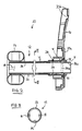
- a bowel management apparatus 10 generally comprises a tube 12 at the distal end of which is provided an annular balloon cuff 14, and at the proximal end is provided a support connector 16.
- the distal end is for insertion into the rectum of a wearer, for example a bedbound person.
- the balloon cuff 14 is inflatable via an inflation conduit 18 for retaining the distal end in the rectum.
- the tube 12 functions to hygienically transport excreted stool and flatus from the body to a fecal collection container (not shown), such as a fecal bag.
- the support connector 16 provides a connection point to the fecal collection container and an attachment point for attaching to the person's bed.
- the support connector 16 comprises an annular landing zone 20a for adhesive attachment to the fecal collection container or an injection molded flange for mechanically coupling to the fecal collection container, and an aperture 20b for receiving an attaching strap (not shown).
- the tube 12 may be of any desired length, for example from about a few centimeters (e.g., the minimum distance for the tube to exit the rectum to at least the exterior skin surface), up to the order of 1 - 2 meters or more (e.g., to provide a tube length sufficient to reach the edge of a bed while still allowing the wearer to move around in the bed).
- the tube 12 consists of a single length of material, but the invention envisages that the tube 12 could be made of plural tube segments.
- the tube 12 generally comprises a first tube member 22 and a second tube member 24 placed one within the other.
- the first tube member 22 is a primary shape defining tube made of a silicone material, for example, silicone rubber. Silicone is chosen for its biocompatibility, flexibility and comfort characteristics.
- the first tube member 22 is soft enough to enable the tube to be flexible and conformable, while being sufficiently stiff to retain an open tubular shape when not compressed.
- the first tube member 22 has a generally round cross-section shape, with an outer diameter of about 2-4 cm, and a wall thickness of between about 0.25 and 5 mm.
- the second tube member 24 is an odor barrier sleeve comprising an odor barrier material.
- the odor barrier material has a greater resistance to transmission or permeation of odors, than silicone, preferably at least an order of magnitude greater.
- the second tube member 24 is generally as flexible as the first tube member 22 so as not to obstruct the flexibility of the tube 12.
- the second tube member 24 has a thinner wall thickness than the first tube 22, for example, not more than about 1/10 of the wall thickness of the first tube 22.
- the second tube member 24 might not retain an open tubular shape itself, but instead, the second tube member 24 is supported by the first tube member 22 to the extent necessary.
- the provision of the second tube member 24 can greatly enhance the odor barrier properties of the tube 12 compared to just the silicone tube member 22 alone.
- the characteristics of silicone material of the first tube member 22 are excellent in many respects, one area where silicone lacks performance is its odor barrier characteristics. Odor leakage may be especially noticeable in longer tube lengths but may also be evident in shorter lengths.
- the invention can significantly enhance the odor barrier properties of both long (e.g., more than about 50cm, or more than 100cm), and short silicone tubes by at least slowing down, or preferably substantially stopping, permeation of unpleasant odors from the silicone tube.
- the provision of the odor barrier as a distinct sleeve member can avoid the problems associated with chemically depositing a thin film coating on the silicone.
- the second tube member 24 will retain its full integrity throughout the use life of the silicone first tube member 22, even with repeated flexing, stretching and twisting of the tube 12 in its normal everyday use.
- plastics film conventionally used for manufacturing ostomy pouches. Such plastics film is relatively inexpensive, strong, has good workability (e.g., with adhesives or welding), known biocompatibility and excellent odor barrier properties.
- An example plastics film comprises an odor barrier of poly(vinylidene chloride) (PVDC). Such a barrier polymer can be coextruded or laminated with one of more layers of ethylene vinyl acetate (EVA).
- PVDC poly(vinylidene chloride)
- EVA ethylene vinyl acetate
- nylon film which provides good odor barrier properties and provides a good adhesive bond to silicone.
- odor barrier materials include poly(vinyl alcohol) (PVOH), ethylene vinyl alcohol copolymers (EVOH), a polyamide or co-polyamide or polyamide blends selected from PA-6, PA-6,6, PA-11, and PA-12, amorphous polyamides, MXD6 polyamide, polyesters (PET), polyester elastomers, glycol-modified polyester (PETG), a polyester or co-polyester blend, poly(acrylonitrile) (PAN), polyurethane (PUR), polyvinyl chloride (PVC), fluoropolymers such as polychlorotrifluoro ethylene (PCTFE), styrene-acrylonitrile copolymers, acrylonitrile-butadiene-styrene terpolymers, poly(methyl methacrylate), styrene-butadiene copolymers, polyacrylonitrile, and homopolymers, copolymers, or blends of above polymers.
- PVOH poly
- the plastics film may be extruded in the tubular sleeve shape, or a sheet of the film material may be rolled around a former and secured in its rolled up form, for example, by adhesive or by a welded seam.
- the sleeve may comprise a single layer of film, a multilayer film, cross wound tube, or the film may be rolled on itself several times.
- the following description describes two alternative embodiments, a first in which the second tube member (odor barrier sleeve) 24 is fitted inside the first tube member 22; and a second embodiment in which the second tube member (odor barrier sleeve) 24 is fitted outside the second tube member 22.
- the following table illustrates the comparative performance of both embodiments compared to a silicone tube without any odor barrier, and a silicone tube with a parylene coating, by using the so-called " Onion Test" (British Standard 7127: Part 101: 1991 ) in which the odor barrier properties are assessed according to whether odor from an onion when contained by the test material in a closed system can be detected by the human nose.
- Oxygen transmission rate is used as a reasonable predictor of the device's low permeability to the smaller odorous molecules in human fecal matter, while onion test is used as an overall predictor of the device's resistance to the permeation of malodoriferous compounds generated from the digestive system in the human body.
- silicone tubing without odor barrier had an extremely high OTR of around 40,000 cc/m 2 /day, and did not provide any resistance against onion odor.
- the parylene coating of silicone tube used in the prior art had better OTR than that of silicone tube without odor barrier material, the level of OTR was still considered high at around 6,000 cc/m 2 /day and did not provide sufficient barrier against onion odor.
- the use of tubular sleeve materials significantly reduced OTR to a range less than 1,000 cc/m 2 /day and preferably less than 500 cc/m 2 /day. As shown in the table, all three examples offered great resistance against onion odor.
- the invention also encompasses the possibility of providing odor barrier sleeve members both inside and outside the silicone tube.
- odor barrier sleeve members both inside and outside the silicone tube.
- the second tube (sleeve) member 24 is provided as an internal liner inside the first tube member 22.
- the second tube member 24 is fastened to the first tube member 22, for example, completely around its circumference at the distal end (i.e., patient end) and substantially along its entire length, or at least at longitudinally and/or circumferentially spaced apart positions, or at least one longitudinal position.
- the attachment may be by means of adhesive.
- the attachment serves to create a seal between the first and second tubes at the patient end and locate the second tube member 24 axially, in order to prevent the second tube member 24 from being dislodged or displaced axially, for example by passage of fecal matter within the tube 12, or if the tube 12 is milked by a caregiver to peristaltically advance fecal matter along the tube 12.
- the fastening may optionally support the second tube member 24 and thus keeps the tubular space generally open and unobstructed by preventing the second tube member from collapsing inside the first tube member 22.
- the second tube member 24 is fastened only at or near one or both ends thereof.
- a vent path "V" is provided for allowing any gas trapped between the first and second tuber members 22 and 24 to escape. Gas may enter the space between the first and second tube members 22 and 24 either during manufacture, or it may permeate through the silicone wall of the first tube member 22. Generally, it is desired to allow such gas to vent away easily, so as to avoid constricting the internal bore inside the first and second tube members 22 and 24.
- the vent path may, for example, comprise a small aperture in the wall of the first tube member and/or a vent aperture at the proximal end of the tube 12.
- An example material for the second tube member 24 is a 75 ⁇ m thick PVdC-containing film from Cryovac. Another preferred example is nylon film.
- the second tube member 24 may have a diameter slightly smaller than the first tube member 22, for example about 1.9 cm, or slightly bigger than the first tube member 22, for example about 2.13 cm.
- the film may be attached in position by any suitable adhesive, for example, a two-part silicone adhesive by Nusil Technology, a RTV silicone adhesive made by CRC Industries, Inc.
- the tube 12 may be made by forming the first and second tube members 22 and 24 separately, then inserting the second tube member 24 inside the first, and advancing one tube member relative to the other, to draw the second tube member 24 to extend completely through the first tube member 22.
- the second tube member 24 sits radially inwardly of any secondary conduits 18 carried by the first tube member 22, such as the inflation conduit 18 mentioned above, and/or an irrigation conduit for irrigating the rectum.
- any secondary conduits 18 carried by the first tube member 22 such as the inflation conduit 18 mentioned above, and/or an irrigation conduit for irrigating the rectum.
- Such an arrangement can allow an external fluid connection to be made through the wall of the first tube member 22 to the secondary conduit 18, without breaching the second tube member 24, and thus without breaching the integrity of the odor barrier.
- This arrangement is especially suitable when the secondary conduit 18 is integrally formed with, or is attached to, the wall of the first tube member 22.
- the secondary conduit 18 is a separate conduit not integrally attached to the first tube member 22, then the secondary conduit 18 could run inside the bore of the second tube member 24 if desired.
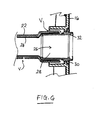
- the tube 12 is coupled to the support coupling 16 by a flanged adapter tube 26.
- the adapter tube 26 generally comprises a tubular spigot 28 with locating flanges 30 and a mouth section 32.
- the tubular spigot 28 is inserted into the proximal end of the first tube member 22 to affix to the proximal end of the first tube member 22 either by adhesive or by a tight friction fit.
- the adapter tube 26 is secured to the support coupling 16 by means of the locating flanges 30 which interlock against the support coupling 16.
- the second tube (sleeve) member 24 is configured to extend longitudinally beyond the proximal end of the first tube member 22, and to pass inside the adapter tube 26 to define a protruding portion 24a that protrudes slightly from the mouth section 32 and the support coupling 16.
- the portion of the second tube (sleeve) member 24 inside the adapter tube 26 is optionally secured to the adapter tube 26, for example, by adhesive, welding or the introduction of an inner ring (shown in phantom at 26a) to trap the film against the inside of the adapter tube.
- the protruding portion 24a fits just inside the aperture of a fecal collection container that is secured to the support coupling 16, to thereby provide a continuous odor barrier from the tube 12, through the adapter tube 26 and support coupling 16 into the fecal collection chamber.
- the protruding portion 24a of the second tube member 24 is folded back around the locating flanges 30 of the adapter tube 26, so as to be trapped between the locating flanges 30 and the support connector 16 when the adapter tube 26 is fitted to the support connector 16. With this configuration, no adhesive is necessary at the proximal end of the tube 12 to fasten the proximal end of the second tube member 24.
- the proximal end of the second tube member 24 again passes inside the adapter tube 26, but is dimensioned not to protrude from the mouth section 32.
- the proximal end of the second tube member 24 is secured to the inner surface of the adapter tube 26, for example, by adhesive, welding or the introduction of an inner ring 26a to trap the film against the inside of the adapter tube.
- the proximal end of the second tube member 24 is not passed inside the adapter tube 26, but instead is passed over the outer surface of the tubular spigot 28 and trapped between the spigot 28 and the proximal end of the first tube member 22.
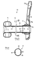
- the second tube member (odor barrier sleeve) 24 is provided as an external sleeve around the first (silicone) tube member 22.
- a feature of an external sleeve is that the second tube member 24 does not occupy any of the internal space of the first tube member 22.
- the second tube member 24 closely conforms to the size of the first tube member 22. This is achieved by using a heat shrinkable material for the second tube member 22.
- plastics film having both heat shrinkable properties and odor barrier properties based on ethylene vinyl alcohol copolymers (EVOH) or poly(vinylidene chloride) (PVDC) is available from Cryovac and Perfecseal.
- the odor barrier is reported to be between 4-50 cc/m 2 /day at 23°C, and the shrink property is reported to be at least 10%, preferably at least 30% at 100°C.
- the plastics film is made into a tube slightly larger in diameter than the first tube member 22. For example, if the outer diameter of the first tube member 22 is about 2.2 cm, then film for the second tube member 24 may be formed into a tube of about 2.5-3.0 cm in diameter. The second tube member 24 is then slid over the first tube member 22, and is heated to shrink down tightly around the surface of the first tube member 22. Any air or other gas trapped between the two tube members 22 and 24 may vent through one or more small vent paths.
- shrinking down the second tube member 24 on to the first tube member 22 can avoid the need for adhesive attachment, but desired adhesive attachment may be used to reinforce the anchoring of the second tube member 24 around the first tube member 22.
- the second tube member 24 can also fit loosely outside of the first tube member 22, and can be attached to each other at or near at least one end or both ends.
- an odor barrier tube member distinct from the silicone tube member
- another way of incorporating an odor barrier material into a silicone tube is by adding, either extrusion, coextrusion, or adhesive lamination, the odor barrier material to the silicone tube.
- the odor barrier layer could be as an exterior layer or a surface layer or in the middle of the silicone tube.
- an adhesive layer is provided to enhance the adhesion between odor material layer and silicone.
- the introduction of the odor barrier layer could be during silicone tube extrusion, for example coextrusion. Or the process can take place after the silicone extrusion, for example, extrusion coating or adhesive lamination.
- the odor barrier could be incorporated into a silicone sheet using adhesives and then the sheet converted into a tube form.
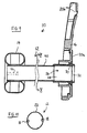
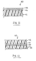
- Figs. 9 and 10 illustrate a third embodiment in which the tube 12 comprises a single tube member 40.
- the wall of the tube member 40 is a laminate comprising at least one layer 42 of silicone based material and at least one layer 44 of odor barrier material.
- the odor barrier material may be any of the examples described hereinbefore.
- the laminate may optionally include one or more adhesive layers 46 for bonding the odor barrier material to the silicone based material.
- the odor barrier layer 44 is provided at a surface portion of the tubing 40. The surface portion may be at the radially outer surface, or the radially inner surface.
- the odor barrier layer 44 is sandwiched in the middle of inner and outer layers 42 of silicone based material.
- the layers 42 of silicone material on either side of the odor barrier layer 44 may be of about the same thickness, one layer 42 may be thicker than the other.
Claims (14)
- Ensemble tubulaire de gestion intestinale (10) destiné à transporter la matière malodorante depuis le rectum, l'ensemble tubulaire de gestion intestinale (10) comprenant :(a) un tube à base de silicone (22) ayant un alésage central pour la matière malodorante, ledit tube (22) ayant une extrémité distale capable d'être insérée et retenue dans le rectum, ledit tube (22) s'étendant vers l'extérieur du rectum pour transporter la matière malodorante depuis le corps ;(b) un élément de manchon tubulaire distinct (24) comprenant un matériau formant barrière aux odeurs, le matériau formant barrière aux odeurs ayant une meilleure résistance à la transmission de gaz que le tube à base de silicone ; et(c) le tube à base de silicone (22) et l'élément de manchon tubulaire (24) étant agencés l'un dans l'autre de telle sorte que l'élément de manchon tubulaire (24) fournit une barrière aux odeurs pour empêcher la fuite d'odeurs émanant de matière malodorante dans l'alésage du tube à base de silicone (22).
- Ensemble tubulaire de gestion intestinale (10) selon la revendication 1, dans lequel l'élément de manchon tubulaire a un taux de transfert d'oxygène (OTR) qui ne dépasse pas 1 000 cm3/m2/jour à 23 °C.
- Ensemble tubulaire de gestion intestinale (10) selon l'une quelconque des revendications précédentes, dans lequel l'élément de manchon tubulaire (24) est agencé à l'intérieur du tube à base de silicone.
- Ensemble tubulaire de gestion intestinale (10) selon l'une quelconque des revendications 1 à 2, dans lequel l'élément de manchon tubulaire est agencé à l'extérieur du tube à base de silicone.
- Ensemble tubulaire de gestion intestinale (10) selon l'une quelconque des revendications précédentes, dans lequel l'élément de manchon tubulaire (24) a une épaisseur de paroi plus fine que celle du tube à base de silicone (22).
- Ensemble tubulaire de gestion intestinale (10) selon l'une quelconque des revendications précédentes, dans lequel au moins une partie de l'élément de manchon tubulaire (24) est fixée au tube à base de silicone (22).
- Ensemble tubulaire de gestion intestinale (10) selon l'une quelconque des revendications précédentes, dans lequel ladite partie est fixée en utilisant au moins l'un des éléments suivants : adhésif ; adhésif à base de silicone thermodurcissable bicomposant ; agent d'étanchéité à base de silicone résistant aux variations de température ; force mécanique ; température ; pression.
- Ensemble tubulaire de gestion intestinale (10) selon la revendication 6 ou 7, dans lequel ladite partie de l'élément de manchon tubulaire (24) est fixée à au moins une extrémité.
- Ensemble tubulaire de gestion intestinale (10) selon l'une quelconque des revendications précédentes, comprenant en outre un tube adaptateur (26) disposé au niveau d'une première extrémité du tube à base de silicone, et dans lequel l'élément de manchon tubulaire (24) est fixé au tube adaptateur (26).
- Ensemble tubulaire de gestion intestinale (10) selon l'une quelconque des revendications précédentes, dans lequel l'élément de manchon tubulaire (24) est choisi parmi : un film tubulaire sans couture ; une feuille de matériau enroulée selon une forme tubulaire.
- Ensemble tubulaire de gestion intestinale (10) selon la revendication 1, dans lequel l'élément de manchon tubulaire (24) est constitué d'un film multicouches, le film multicouches incluant ledit matériau formant barrière aux odeurs qui est au moins un élément choisi parmi les éléments suivants : polychlorure de vinylidène (PVDC) ; alcool polyvinylique (PVOH) ; copolymère éthylène/alcool vinylique (EVOH) ; polyamide (nylon) ou mélanges de copolyamides ou de polyamides choisis parmi PA-6, PA-6,6, PA-11 et PA-12, polyamides amorphes, polyamide MXD6 ; polyester (PET) ; élastomère de polyester ; polyester modifié par du glycol (PETG) ; mélange de polyesters ou de copolyesters ; polyacrylonitrile (PAN) ; polyuréthane (PUR) ; polychlorure de vinyle (PVC) ; polychlorotrifluoroéthylène (PCTFE) ; copolymère styrène/acrylonitrile ; terpolymère acrylonitrile/butadiène/styrène ; polyméthacrylate de méthyle ; copolymère styrène/butadiène.
- Ensemble tubulaire de gestion intestinale (10) pour transporter la matière malodorante depuis le rectum, un tube (40) étant constitué d'un matériau stratifié comprenant :(a) une couche de matériau à base de silicone (42) ; et(b) une couche de matériau formant barrière aux odeurs (44) stratifié avec le matériau à base de silicone (42) pour empêcher la fuite d'odeurs émanant de matière malodorante dans ledit tube (40) ;dans lequel le matériau stratifié est tel que le matériau formant barrière aux odeurs (44) est stratifié avec le matériau à base de silicone (42) avant, ou au moment de, la formation du matériau à base de silicone (42) selon une forme de tube, ledit tube ayant une extrémité distale capable d'être insérée et retenue dans le rectum, ledit tube étant dimensionné de manière prédéterminée de façon à s'étendre vers l'extérieur du rectum.
- Ensemble tubulaire de gestion intestinale (10) selon la revendication 12, comprenant en outre une couche adhésive (46) pour coller la couche de matériau formant barrière aux odeurs (44) à la couche de matériau à base de silicone (42).
- Ensemble tubulaire de gestion intestinale (10) selon l'une quelconque des revendications 1 à 10, 12 et 13, dans lequel le matériau formant barrière aux odeurs comprend au moins un élément choisi parmi les éléments suivants : polychlorure de vinylidène (PVDC) ; alcool polyvinylique (PVOH) ; copolymère éthylène/alcool vinylique (EVOH) ; polyamide (nylon) ou mélanges de copolyamides ou de polyamides choisis parmi PA-6, PA-6,6, PA-11 et PA-12, polyamides amorphes, polyamide MXD6 ; polyester (PET) ; élastomère de polyester ; polyester modifié par du glycol (PETG) ; mélange de polyesters ou de copolyesters ; polyacrylonitrile (PAN) ; polyuréthane (PUR) ; polychlorure de vinyle (PVC) ; polychlorotrifluoroéthylène (PCTFE) ;
copolymère styrène/acrylonitrile ; terpolymère acrylonitrile/butadiène/styrène ; polyméthacrylate de méthyle ; copolymère styrène/butadiène.
Applications Claiming Priority (2)
| Application Number | Priority Date | Filing Date | Title |
|---|---|---|---|
| US86305306P | 2006-10-26 | 2006-10-26 | |
| PCT/US2007/082312 WO2008052018A2 (fr) | 2006-10-26 | 2007-10-24 | Tube à base de silicone pour transporter des matières malodorantes provenant du corps humain |
Publications (3)
| Publication Number | Publication Date |
|---|---|
| EP2104478A2 EP2104478A2 (fr) | 2009-09-30 |
| EP2104478A4 EP2104478A4 (fr) | 2012-01-25 |
| EP2104478B1 true EP2104478B1 (fr) | 2013-11-20 |
Family
ID=39325363
Family Applications (1)
| Application Number | Title | Priority Date | Filing Date |
|---|---|---|---|
| EP07863463.1A Active EP2104478B1 (fr) | 2006-10-26 | 2007-10-24 | Tube à base de silicone pour transporter des matières malodorantes provenant du corps humain |
Country Status (11)
| Country | Link |
|---|---|
| US (1) | US8323254B2 (fr) |
| EP (1) | EP2104478B1 (fr) |
| JP (1) | JP5624321B2 (fr) |
| CN (1) | CN101557780B (fr) |
| AU (1) | AU2007308971B2 (fr) |
| BR (1) | BRPI0717337A2 (fr) |
| CA (1) | CA2667822C (fr) |
| MX (1) | MX2009004184A (fr) |
| NZ (1) | NZ577154A (fr) |
| RU (1) | RU2454976C2 (fr) |
| WO (1) | WO2008052018A2 (fr) |
Families Citing this family (22)
| Publication number | Priority date | Publication date | Assignee | Title |
|---|---|---|---|---|
| US8936583B2 (en) | 2007-09-28 | 2015-01-20 | Hollister Incorporated | Multi-layer catheter tubes with odor barrier |
| EP2203208B1 (fr) | 2007-09-28 | 2019-06-26 | Hollister Incorporated | Tube multicouche anti-odeur, et combinaison d'un tube anti-odeur et d'un sac de collecte anti-odeur |
| US8795234B2 (en) | 2010-11-30 | 2014-08-05 | Becton, Dickinson And Company | Integrated spring-activated ballistic insertion for drug infusion device |
| US9072875B2 (en) | 2011-02-17 | 2015-07-07 | Yun Jin | Valve system for inflatable medical device |
| EP2686031B1 (fr) * | 2011-03-17 | 2020-02-12 | ConvaTec Technologies Inc. | Cathéter fécal ou poche de stomie en élastomère à fonction de barrière élevée |
| GB201115160D0 (en) | 2011-09-02 | 2011-10-19 | Trio Healthcare Ltd | Discharge solidifier and malodour control |
| BR112014011877A2 (pt) | 2011-11-16 | 2017-05-16 | Convatec Technologies Inc | aparelho para prevenir inflação excessiva do balão de retenção em cateteres e dispositivos de via aérea médicos |
| DK2620168T3 (da) * | 2012-01-27 | 2020-06-02 | Hollister Inc | Flerlagskateterslanger med lugtbarriere |
| CA2918607C (fr) | 2013-08-01 | 2024-02-20 | Convatec Technologies Inc. | Raccord de poche a fermeture automatique |
| US20150100033A1 (en) * | 2013-10-03 | 2015-04-09 | Kristopher Mark Weide | Semi-rigid device for sealing and allowing continuous drainage of colostomy bags |
| KR101639012B1 (ko) * | 2013-12-19 | 2016-07-14 | 경북대학교 산학협력단 | 직장 문합 보호용 장치 |
| TW201709946A (zh) | 2015-05-18 | 2017-03-16 | 康瓦鐵克科技股份有限公司 | 彈簧負載袋連接器 |
| JP7018389B2 (ja) | 2015-10-29 | 2022-02-10 | コンバテック・テクノロジーズ・インコーポレイテッド | 膨張可能な装置用弁システム |
| WO2017079532A1 (fr) * | 2015-11-06 | 2017-05-11 | Avent, Inc. | Dispositif, appareil et système de stomie |
| WO2018071742A1 (fr) * | 2016-10-14 | 2018-04-19 | Cryovac, Inc. | Film d'emballage pour produit sensible organoleptique, et procédé, article d'emballage et produit emballé correspondant |
| RU183249U1 (ru) * | 2017-12-22 | 2018-09-14 | Доброслав Викторович Ударцев | Устройство для отвода и сбора кишечных газов |
| US11583432B2 (en) | 2017-12-22 | 2023-02-21 | Dobroslav Viktorovich UDARTSEV | Device for discharge and collection of intestinal gases |
| BR112020014059A2 (pt) | 2018-01-19 | 2020-12-01 | Coloplast A/S | sistema para aplicar uma cobertura de estoma, cobertura de estoma, e, kit de peças. |
| EP3760244A4 (fr) * | 2018-02-28 | 2021-09-08 | Udartsev, Dobroslav Viktorovich | Collecteur de gaz |
| RU184950U1 (ru) * | 2018-02-28 | 2018-11-15 | Доброслав Викторович Ударцев | Газосборник |
| RU2683849C1 (ru) * | 2018-07-30 | 2019-04-02 | Владимир Александрович Парамошко | Способ отправления естественных надобностей |
| DE102020002764A1 (de) * | 2020-04-28 | 2021-10-28 | Advanced Medical Balloons Gmbh | Vorrichtung für die medizinische Ableitung und Zuleitung von Substanzen mit geruchsreduzierenden Eigenschaften und deren kosteneffiziente Herstellung |
Family Cites Families (19)
| Publication number | Priority date | Publication date | Assignee | Title |
|---|---|---|---|---|
| US4381765A (en) | 1981-04-02 | 1983-05-03 | Waters Instruments, Inc. | Ileostomy valve |
| SU1199245A1 (ru) * | 1984-05-14 | 1985-12-23 | Всесоюзный научно-исследовательский институт текстильно-галантерейной промышленности | Дезодорирующа прокладка дл больных с колостомой |
| US4721508A (en) | 1984-10-09 | 1988-01-26 | Waters Instruments, Inc. | Ostomy prosthesis |
| US4662890A (en) | 1984-10-09 | 1987-05-05 | Waters Instruments, Inc. | Tubular medical prosthesis |
| GB8609307D0 (en) | 1986-04-16 | 1986-05-21 | Insituform Group Ltd | Lining of piplines |
| US5093194A (en) * | 1989-11-01 | 1992-03-03 | Mobil Oil Corporation | Oriented multilayer heat sealable packaging film |
| CA2043301C (fr) * | 1990-07-03 | 1996-06-18 | Jeffrey Michael Schuetz | Film multicouche formant barriere olfactive grace a un copolymere de chlorure de vinylidene |
| CA2048168A1 (fr) * | 1990-08-03 | 1992-02-04 | John T. Felts | Materiau pare-vapeur en feuille mince a base d'oxyde de silicium |
| AU669754B2 (en) * | 1992-12-18 | 1996-06-20 | Becton Dickinson & Company | Barrier coating |
| US5569216A (en) | 1993-12-02 | 1996-10-29 | Kim; Jae H. | Multipurpose colostomy device having balloons on an end thereof |
| US5522801A (en) * | 1995-01-18 | 1996-06-04 | Wang; Abe | Integrate-forming silicone balloon catheter |
| JP3866381B2 (ja) * | 1997-07-28 | 2007-01-10 | 旭化成ライフ&リビング株式会社 | 塩化ビニリデン系樹脂組成物からなるフィルム、及びオストミーバッグ |
| US6050982A (en) * | 1997-11-03 | 2000-04-18 | Wheeler; Alton D. | Concealed colostomy apparatus and method |
| US6050928A (en) | 1998-10-13 | 2000-04-18 | Tsai; Shao-Nong | Paper folding device |
| US7147627B2 (en) | 2002-08-21 | 2006-12-12 | Hollister Incorporated | Bowel management system |
| US8016816B2 (en) * | 2003-09-09 | 2011-09-13 | Convatec Technologies Inc. | Fecal management appliance and method and apparatus for introducing same |
| AU2003292521A1 (en) * | 2003-11-10 | 2005-05-26 | Sapi Med S.P.A. | Transanal device |
| US7727188B2 (en) | 2003-12-17 | 2010-06-01 | Convatec Technologies Inc. | Balloon catheter with positioning pocket |
| US8075540B2 (en) * | 2004-11-09 | 2011-12-13 | Hollister Incorporated | Bowel management system with physiologic sensors |
-
2007
- 2007-10-24 NZ NZ577154A patent/NZ577154A/en not_active IP Right Cessation
- 2007-10-24 BR BRPI0717337-7A2A patent/BRPI0717337A2/pt not_active Application Discontinuation
- 2007-10-24 CN CN2007800398820A patent/CN101557780B/zh active Active
- 2007-10-24 MX MX2009004184A patent/MX2009004184A/es active IP Right Grant
- 2007-10-24 US US11/877,691 patent/US8323254B2/en active Active
- 2007-10-24 AU AU2007308971A patent/AU2007308971B2/en active Active
- 2007-10-24 CA CA2667822A patent/CA2667822C/fr active Active
- 2007-10-24 WO PCT/US2007/082312 patent/WO2008052018A2/fr active Application Filing
- 2007-10-24 RU RU2009119733/14A patent/RU2454976C2/ru active
- 2007-10-24 EP EP07863463.1A patent/EP2104478B1/fr active Active
- 2007-10-24 JP JP2009534830A patent/JP5624321B2/ja active Active
Also Published As
| Publication number | Publication date |
|---|---|
| EP2104478A2 (fr) | 2009-09-30 |
| CN101557780B (zh) | 2012-11-14 |
| AU2007308971A1 (en) | 2008-05-02 |
| EP2104478A4 (fr) | 2012-01-25 |
| RU2454976C2 (ru) | 2012-07-10 |
| WO2008052018A3 (fr) | 2008-08-28 |
| JP2010508085A (ja) | 2010-03-18 |
| CA2667822C (fr) | 2015-02-03 |
| WO2008052018A2 (fr) | 2008-05-02 |
| JP5624321B2 (ja) | 2014-11-12 |
| CA2667822A1 (fr) | 2008-05-02 |
| BRPI0717337A2 (pt) | 2013-12-10 |
| RU2009119733A (ru) | 2010-12-10 |
| NZ577154A (en) | 2012-06-29 |
| US8323254B2 (en) | 2012-12-04 |
| AU2007308971B2 (en) | 2013-07-18 |
| MX2009004184A (es) | 2009-09-07 |
| US20080103463A1 (en) | 2008-05-01 |
| CN101557780A (zh) | 2009-10-14 |
Similar Documents
| Publication | Publication Date | Title |
|---|---|---|
| EP2104478B1 (fr) | Tube à base de silicone pour transporter des matières malodorantes provenant du corps humain | |
| JP5453275B2 (ja) | 排便システム用のカテーテルチューブ | |
| US20240122738A1 (en) | Ostomy wafer construction | |
| KR100439773B1 (ko) | 의료용비-pvc다층튜브와그제조공정및사용 | |
| EP2007448B1 (fr) | Tube de cathéter, cathéter et ensemble cathéter | |
| EP0932374B1 (fr) | Membranes adaptees a l'usage medical | |
| US20130096523A1 (en) | Multilayer backing film for adhesive skin barrier of ostomy appliance | |
| US9452080B2 (en) | Fecal drainage system with multi-layer odor barrier catheter tube | |
| JP2010508085A5 (fr) | ||
| AU2013200357B2 (en) | Multi-layer catheter tubes with odor barrier | |
| US6127009A (en) | Dispenser unit, process for manufacturing the same and its use | |
| KR20010089426A (ko) | 2겹 비삼투성 벌룬 카테터 | |
| RU2197219C2 (ru) | Выдачной узел и способ его изготовления | |
| JPH01294033A (ja) | 冷媒輸送用ホース |
Legal Events
| Date | Code | Title | Description |
|---|---|---|---|
| PUAI | Public reference made under article 153(3) epc to a published international application that has entered the european phase |
Free format text: ORIGINAL CODE: 0009012 |
|
| 17P | Request for examination filed |
Effective date: 20090526 |
|
| AK | Designated contracting states |
Kind code of ref document: A2 Designated state(s): AT BE BG CH CY CZ DE DK EE ES FI FR GB GR HU IE IS IT LI LT LU LV MC MT NL PL PT RO SE SI SK TR |
|
| DAX | Request for extension of the european patent (deleted) | ||
| RAP1 | Party data changed (applicant data changed or rights of an application transferred) |
Owner name: CONVATEC TECHNOLOGIES INC. |
|
| A4 | Supplementary search report drawn up and despatched |
Effective date: 20111223 |
|
| RIC1 | Information provided on ipc code assigned before grant |
Ipc: A61F 5/451 20060101ALI20111219BHEP Ipc: A61F 5/445 20060101ALI20111219BHEP Ipc: A61F 5/44 20060101ALI20111219BHEP Ipc: A61F 5/00 20060101AFI20111219BHEP Ipc: A61F 2/00 20060101ALI20111219BHEP |
|
| REG | Reference to a national code |
Ref country code: DE Ref legal event code: R079 Ref document number: 602007033963 Country of ref document: DE Free format text: PREVIOUS MAIN CLASS: A61F0005445000 Ipc: A61F0005000000 |
|
| RIC1 | Information provided on ipc code assigned before grant |
Ipc: A61F 5/445 20060101ALI20130116BHEP Ipc: A61F 5/00 20060101AFI20130116BHEP Ipc: A61F 2/00 20060101ALI20130116BHEP Ipc: A61F 5/44 20060101ALI20130116BHEP Ipc: A61F 5/451 20060101ALI20130116BHEP |
|
| GRAP | Despatch of communication of intention to grant a patent |
Free format text: ORIGINAL CODE: EPIDOSNIGR1 |
|
| INTG | Intention to grant announced |
Effective date: 20130529 |
|
| GRAS | Grant fee paid |
Free format text: ORIGINAL CODE: EPIDOSNIGR3 |
|
| GRAA | (expected) grant |
Free format text: ORIGINAL CODE: 0009210 |
|
| AK | Designated contracting states |
Kind code of ref document: B1 Designated state(s): AT BE BG CH CY CZ DE DK EE ES FI FR GB GR HU IE IS IT LI LT LU LV MC MT NL PL PT RO SE SI SK TR |
|
| REG | Reference to a national code |
Ref country code: GB Ref legal event code: FG4D |
|
| REG | Reference to a national code |
Ref country code: CH Ref legal event code: EP |
|
| REG | Reference to a national code |
Ref country code: AT Ref legal event code: REF Ref document number: 641120 Country of ref document: AT Kind code of ref document: T Effective date: 20131215 |
|
| REG | Reference to a national code |
Ref country code: IE Ref legal event code: FG4D |
|
| REG | Reference to a national code |
Ref country code: DE Ref legal event code: R096 Ref document number: 602007033963 Country of ref document: DE Effective date: 20140116 |
|
| REG | Reference to a national code |
Ref country code: NL Ref legal event code: VDEP Effective date: 20131120 |
|
| REG | Reference to a national code |
Ref country code: AT Ref legal event code: MK05 Ref document number: 641120 Country of ref document: AT Kind code of ref document: T Effective date: 20131120 |
|
| REG | Reference to a national code |
Ref country code: LT Ref legal event code: MG4D |
|
| PG25 | Lapsed in a contracting state [announced via postgrant information from national office to epo] |
Ref country code: SE Free format text: LAPSE BECAUSE OF FAILURE TO SUBMIT A TRANSLATION OF THE DESCRIPTION OR TO PAY THE FEE WITHIN THE PRESCRIBED TIME-LIMIT Effective date: 20131120 Ref country code: NL Free format text: LAPSE BECAUSE OF FAILURE TO SUBMIT A TRANSLATION OF THE DESCRIPTION OR TO PAY THE FEE WITHIN THE PRESCRIBED TIME-LIMIT Effective date: 20131120 Ref country code: LT Free format text: LAPSE BECAUSE OF FAILURE TO SUBMIT A TRANSLATION OF THE DESCRIPTION OR TO PAY THE FEE WITHIN THE PRESCRIBED TIME-LIMIT Effective date: 20131120 Ref country code: FI Free format text: LAPSE BECAUSE OF FAILURE TO SUBMIT A TRANSLATION OF THE DESCRIPTION OR TO PAY THE FEE WITHIN THE PRESCRIBED TIME-LIMIT Effective date: 20131120 Ref country code: IS Free format text: LAPSE BECAUSE OF FAILURE TO SUBMIT A TRANSLATION OF THE DESCRIPTION OR TO PAY THE FEE WITHIN THE PRESCRIBED TIME-LIMIT Effective date: 20140320 |
|
| PG25 | Lapsed in a contracting state [announced via postgrant information from national office to epo] |
Ref country code: BE Free format text: LAPSE BECAUSE OF FAILURE TO SUBMIT A TRANSLATION OF THE DESCRIPTION OR TO PAY THE FEE WITHIN THE PRESCRIBED TIME-LIMIT Effective date: 20131120 Ref country code: ES Free format text: LAPSE BECAUSE OF FAILURE TO SUBMIT A TRANSLATION OF THE DESCRIPTION OR TO PAY THE FEE WITHIN THE PRESCRIBED TIME-LIMIT Effective date: 20131120 Ref country code: LV Free format text: LAPSE BECAUSE OF FAILURE TO SUBMIT A TRANSLATION OF THE DESCRIPTION OR TO PAY THE FEE WITHIN THE PRESCRIBED TIME-LIMIT Effective date: 20131120 Ref country code: AT Free format text: LAPSE BECAUSE OF FAILURE TO SUBMIT A TRANSLATION OF THE DESCRIPTION OR TO PAY THE FEE WITHIN THE PRESCRIBED TIME-LIMIT Effective date: 20131120 |
|
| PG25 | Lapsed in a contracting state [announced via postgrant information from national office to epo] |
Ref country code: PT Free format text: LAPSE BECAUSE OF FAILURE TO SUBMIT A TRANSLATION OF THE DESCRIPTION OR TO PAY THE FEE WITHIN THE PRESCRIBED TIME-LIMIT Effective date: 20140320 |
|
| PG25 | Lapsed in a contracting state [announced via postgrant information from national office to epo] |
Ref country code: EE Free format text: LAPSE BECAUSE OF FAILURE TO SUBMIT A TRANSLATION OF THE DESCRIPTION OR TO PAY THE FEE WITHIN THE PRESCRIBED TIME-LIMIT Effective date: 20131120 |
|
| REG | Reference to a national code |
Ref country code: DE Ref legal event code: R097 Ref document number: 602007033963 Country of ref document: DE |
|
| PG25 | Lapsed in a contracting state [announced via postgrant information from national office to epo] |
Ref country code: PL Free format text: LAPSE BECAUSE OF FAILURE TO SUBMIT A TRANSLATION OF THE DESCRIPTION OR TO PAY THE FEE WITHIN THE PRESCRIBED TIME-LIMIT Effective date: 20131120 Ref country code: SK Free format text: LAPSE BECAUSE OF FAILURE TO SUBMIT A TRANSLATION OF THE DESCRIPTION OR TO PAY THE FEE WITHIN THE PRESCRIBED TIME-LIMIT Effective date: 20131120 Ref country code: RO Free format text: LAPSE BECAUSE OF FAILURE TO SUBMIT A TRANSLATION OF THE DESCRIPTION OR TO PAY THE FEE WITHIN THE PRESCRIBED TIME-LIMIT Effective date: 20131120 Ref country code: CZ Free format text: LAPSE BECAUSE OF FAILURE TO SUBMIT A TRANSLATION OF THE DESCRIPTION OR TO PAY THE FEE WITHIN THE PRESCRIBED TIME-LIMIT Effective date: 20131120 |
|
| PLBE | No opposition filed within time limit |
Free format text: ORIGINAL CODE: 0009261 |
|
| STAA | Information on the status of an ep patent application or granted ep patent |
Free format text: STATUS: NO OPPOSITION FILED WITHIN TIME LIMIT |
|
| PG25 | Lapsed in a contracting state [announced via postgrant information from national office to epo] |
Ref country code: DK Free format text: LAPSE BECAUSE OF FAILURE TO SUBMIT A TRANSLATION OF THE DESCRIPTION OR TO PAY THE FEE WITHIN THE PRESCRIBED TIME-LIMIT Effective date: 20131120 |
|
| 26N | No opposition filed |
Effective date: 20140821 |
|
| REG | Reference to a national code |
Ref country code: DE Ref legal event code: R097 Ref document number: 602007033963 Country of ref document: DE Effective date: 20140821 |
|
| PG25 | Lapsed in a contracting state [announced via postgrant information from national office to epo] |
Ref country code: SI Free format text: LAPSE BECAUSE OF FAILURE TO SUBMIT A TRANSLATION OF THE DESCRIPTION OR TO PAY THE FEE WITHIN THE PRESCRIBED TIME-LIMIT Effective date: 20131120 |
|
| PG25 | Lapsed in a contracting state [announced via postgrant information from national office to epo] |
Ref country code: LU Free format text: LAPSE BECAUSE OF FAILURE TO SUBMIT A TRANSLATION OF THE DESCRIPTION OR TO PAY THE FEE WITHIN THE PRESCRIBED TIME-LIMIT Effective date: 20141024 Ref country code: MC Free format text: LAPSE BECAUSE OF FAILURE TO SUBMIT A TRANSLATION OF THE DESCRIPTION OR TO PAY THE FEE WITHIN THE PRESCRIBED TIME-LIMIT Effective date: 20131120 |
|
| REG | Reference to a national code |
Ref country code: CH Ref legal event code: PL |
|
| REG | Reference to a national code |
Ref country code: IE Ref legal event code: MM4A |
|
| PG25 | Lapsed in a contracting state [announced via postgrant information from national office to epo] |
Ref country code: CH Free format text: LAPSE BECAUSE OF NON-PAYMENT OF DUE FEES Effective date: 20141031 Ref country code: LI Free format text: LAPSE BECAUSE OF NON-PAYMENT OF DUE FEES Effective date: 20141031 |
|
| PG25 | Lapsed in a contracting state [announced via postgrant information from national office to epo] |
Ref country code: IT Free format text: LAPSE BECAUSE OF FAILURE TO SUBMIT A TRANSLATION OF THE DESCRIPTION OR TO PAY THE FEE WITHIN THE PRESCRIBED TIME-LIMIT Effective date: 20131120 |
|
| PG25 | Lapsed in a contracting state [announced via postgrant information from national office to epo] |
Ref country code: IE Free format text: LAPSE BECAUSE OF NON-PAYMENT OF DUE FEES Effective date: 20141024 |
|
| PG25 | Lapsed in a contracting state [announced via postgrant information from national office to epo] |
Ref country code: BG Free format text: LAPSE BECAUSE OF FAILURE TO SUBMIT A TRANSLATION OF THE DESCRIPTION OR TO PAY THE FEE WITHIN THE PRESCRIBED TIME-LIMIT Effective date: 20131120 |
|
| PG25 | Lapsed in a contracting state [announced via postgrant information from national office to epo] |
Ref country code: CY Free format text: LAPSE BECAUSE OF FAILURE TO SUBMIT A TRANSLATION OF THE DESCRIPTION OR TO PAY THE FEE WITHIN THE PRESCRIBED TIME-LIMIT Effective date: 20131120 Ref country code: GR Free format text: LAPSE BECAUSE OF FAILURE TO SUBMIT A TRANSLATION OF THE DESCRIPTION OR TO PAY THE FEE WITHIN THE PRESCRIBED TIME-LIMIT Effective date: 20140221 |
|
| PG25 | Lapsed in a contracting state [announced via postgrant information from national office to epo] |
Ref country code: HU Free format text: LAPSE BECAUSE OF FAILURE TO SUBMIT A TRANSLATION OF THE DESCRIPTION OR TO PAY THE FEE WITHIN THE PRESCRIBED TIME-LIMIT; INVALID AB INITIO Effective date: 20071024 Ref country code: TR Free format text: LAPSE BECAUSE OF FAILURE TO SUBMIT A TRANSLATION OF THE DESCRIPTION OR TO PAY THE FEE WITHIN THE PRESCRIBED TIME-LIMIT Effective date: 20131120 Ref country code: MT Free format text: LAPSE BECAUSE OF FAILURE TO SUBMIT A TRANSLATION OF THE DESCRIPTION OR TO PAY THE FEE WITHIN THE PRESCRIBED TIME-LIMIT Effective date: 20131120 |
|
| REG | Reference to a national code |
Ref country code: FR Ref legal event code: PLFP Year of fee payment: 10 |
|
| REG | Reference to a national code |
Ref country code: FR Ref legal event code: PLFP Year of fee payment: 11 |
|
| REG | Reference to a national code |
Ref country code: FR Ref legal event code: PLFP Year of fee payment: 12 |
|
| REG | Reference to a national code |
Ref country code: DE Ref legal event code: R082 Ref document number: 602007033963 Country of ref document: DE Representative=s name: GLEISS GROSSE SCHRELL UND PARTNER MBB PATENTAN, DE |
|
| REG | Reference to a national code |
Ref country code: DE Ref legal event code: R082 Ref document number: 602007033963 Country of ref document: DE Representative=s name: GLEISS GROSSE SCHRELL UND PARTNER MBB PATENTAN, DE |
|
| PGFP | Annual fee paid to national office [announced via postgrant information from national office to epo] |
Ref country code: FR Payment date: 20220920 Year of fee payment: 16 |
|
| P01 | Opt-out of the competence of the unified patent court (upc) registered |
Effective date: 20230526 |
|
| PGFP | Annual fee paid to national office [announced via postgrant information from national office to epo] |
Ref country code: GB Payment date: 20230920 Year of fee payment: 17 |
|
| PGFP | Annual fee paid to national office [announced via postgrant information from national office to epo] |
Ref country code: DE Payment date: 20230920 Year of fee payment: 17 |