EP2104478B1 - Silicone based tube for transporting malodoriforous matter from the human body - Google Patents
Silicone based tube for transporting malodoriforous matter from the human body Download PDFInfo
- Publication number
- EP2104478B1 EP2104478B1 EP07863463.1A EP07863463A EP2104478B1 EP 2104478 B1 EP2104478 B1 EP 2104478B1 EP 07863463 A EP07863463 A EP 07863463A EP 2104478 B1 EP2104478 B1 EP 2104478B1
- Authority
- EP
- European Patent Office
- Prior art keywords
- tube
- tubular
- silicone based
- silicone
- management assembly
- Prior art date
- Legal status (The legal status is an assumption and is not a legal conclusion. Google has not performed a legal analysis and makes no representation as to the accuracy of the status listed.)
- Active
Links
- 229920001296 polysiloxane Polymers 0.000 title claims abstract description 83
- 235000019645 odor Nutrition 0.000 claims abstract description 88
- 230000004888 barrier function Effects 0.000 claims abstract description 76
- 239000000463 material Substances 0.000 claims abstract description 48
- 239000010410 layer Substances 0.000 claims description 29
- -1 poly(vinylidene chloride) Polymers 0.000 claims description 27
- 229920000728 polyester Polymers 0.000 claims description 24
- 239000000853 adhesive Substances 0.000 claims description 18
- 230000001070 adhesive effect Effects 0.000 claims description 18
- 239000004952 Polyamide Substances 0.000 claims description 12
- 229920002647 polyamide Polymers 0.000 claims description 12
- 239000002210 silicon-based material Substances 0.000 claims description 12
- 229920000219 Ethylene vinyl alcohol Polymers 0.000 claims description 11
- 210000000664 rectum Anatomy 0.000 claims description 11
- 229920001328 Polyvinylidene chloride Polymers 0.000 claims description 10
- 230000005540 biological transmission Effects 0.000 claims description 10
- 239000007789 gas Substances 0.000 claims description 9
- 239000000203 mixture Substances 0.000 claims description 9
- 229920002635 polyurethane Polymers 0.000 claims description 8
- 239000004814 polyurethane Substances 0.000 claims description 8
- 229920002451 polyvinyl alcohol Polymers 0.000 claims description 8
- 229920002493 poly(chlorotrifluoroethylene) Polymers 0.000 claims description 7
- 239000005023 polychlorotrifluoroethylene (PCTFE) polymer Substances 0.000 claims description 7
- 239000004715 ethylene vinyl alcohol Substances 0.000 claims description 6
- QVGXLLKOCUKJST-UHFFFAOYSA-N atomic oxygen Chemical compound [O] QVGXLLKOCUKJST-UHFFFAOYSA-N 0.000 claims description 5
- 239000001301 oxygen Substances 0.000 claims description 5
- 229910052760 oxygen Inorganic materials 0.000 claims description 5
- 101000576320 Homo sapiens Max-binding protein MNT Proteins 0.000 claims description 4
- 239000004677 Nylon Substances 0.000 claims description 4
- 229920000571 Nylon 11 Polymers 0.000 claims description 4
- 229920000299 Nylon 12 Polymers 0.000 claims description 4
- 229920006121 Polyxylylene adipamide Polymers 0.000 claims description 4
- 229920006020 amorphous polyamide Polymers 0.000 claims description 4
- 229920006018 co-polyamide Polymers 0.000 claims description 4
- 229920001971 elastomer Polymers 0.000 claims description 4
- 239000000806 elastomer Substances 0.000 claims description 4
- 229920001778 nylon Polymers 0.000 claims description 4
- 229920003229 poly(methyl methacrylate) Polymers 0.000 claims description 4
- 229920002285 poly(styrene-co-acrylonitrile) Polymers 0.000 claims description 4
- 239000004926 polymethyl methacrylate Substances 0.000 claims description 4
- 239000004800 polyvinyl chloride Substances 0.000 claims description 4
- 229920003048 styrene butadiene rubber Polymers 0.000 claims description 4
- 239000012790 adhesive layer Substances 0.000 claims description 3
- 239000013464 silicone adhesive Substances 0.000 claims description 3
- 230000015572 biosynthetic process Effects 0.000 claims description 2
- 229920002631 room-temperature vulcanizate silicone Polymers 0.000 claims description 2
- XECAHXYUAAWDEL-UHFFFAOYSA-N acrylonitrile butadiene styrene Chemical compound C=CC=C.C=CC#N.C=CC1=CC=CC=C1 XECAHXYUAAWDEL-UHFFFAOYSA-N 0.000 claims 2
- 239000002648 laminated material Substances 0.000 claims 2
- 229920001897 terpolymer Polymers 0.000 claims 2
- 238000013007 heat curing Methods 0.000 claims 1
- 239000004590 silicone sealant Substances 0.000 claims 1
- 230000002550 fecal effect Effects 0.000 abstract description 10
- 239000010408 film Substances 0.000 description 27
- 238000000576 coating method Methods 0.000 description 14
- 239000011248 coating agent Substances 0.000 description 13
- 229920000052 poly(p-xylylene) Polymers 0.000 description 12
- 238000004519 manufacturing process Methods 0.000 description 8
- 241000234282 Allium Species 0.000 description 7
- 235000002732 Allium cepa var. cepa Nutrition 0.000 description 7
- 230000008878 coupling Effects 0.000 description 7
- 238000010168 coupling process Methods 0.000 description 7
- 238000005859 coupling reaction Methods 0.000 description 7
- 238000000034 method Methods 0.000 description 6
- 229920003023 plastic Polymers 0.000 description 6
- 239000004033 plastic Substances 0.000 description 6
- 238000001125 extrusion Methods 0.000 description 5
- 210000003608 fece Anatomy 0.000 description 5
- 229920002239 polyacrylonitrile Polymers 0.000 description 5
- 238000012360 testing method Methods 0.000 description 5
- 238000003855 Adhesive Lamination Methods 0.000 description 4
- 238000000151 deposition Methods 0.000 description 4
- 238000005336 cracking Methods 0.000 description 3
- 238000005137 deposition process Methods 0.000 description 3
- 238000007765 extrusion coating Methods 0.000 description 3
- 238000009501 film coating Methods 0.000 description 3
- 206010016766 flatulence Diseases 0.000 description 3
- 230000004048 modification Effects 0.000 description 3
- 238000012986 modification Methods 0.000 description 3
- 229920006284 nylon film Polymers 0.000 description 3
- 230000008569 process Effects 0.000 description 3
- 239000002344 surface layer Substances 0.000 description 3
- 239000010409 thin film Substances 0.000 description 3
- 238000003466 welding Methods 0.000 description 3
- 229920000122 acrylonitrile butadiene styrene Polymers 0.000 description 2
- 238000004873 anchoring Methods 0.000 description 2
- 229920000642 polymer Polymers 0.000 description 2
- 238000007789 sealing Methods 0.000 description 2
- 238000005452 bending Methods 0.000 description 1
- 230000000052 comparative effect Effects 0.000 description 1
- 150000001875 compounds Chemical class 0.000 description 1
- 230000001010 compromised effect Effects 0.000 description 1
- 229920001577 copolymer Polymers 0.000 description 1
- 230000001419 dependent effect Effects 0.000 description 1
- 210000002249 digestive system Anatomy 0.000 description 1
- 238000006073 displacement reaction Methods 0.000 description 1
- 238000005516 engineering process Methods 0.000 description 1
- 230000002708 enhancing effect Effects 0.000 description 1
- 239000005038 ethylene vinyl acetate Substances 0.000 description 1
- 230000003203 everyday effect Effects 0.000 description 1
- 239000012530 fluid Substances 0.000 description 1
- 229920002313 fluoropolymer Polymers 0.000 description 1
- 239000004811 fluoropolymer Substances 0.000 description 1
- 239000002654 heat shrinkable material Substances 0.000 description 1
- 229920001519 homopolymer Polymers 0.000 description 1
- 238000002347 injection Methods 0.000 description 1
- 239000007924 injection Substances 0.000 description 1
- 238000003780 insertion Methods 0.000 description 1
- 230000037431 insertion Effects 0.000 description 1
- 230000002262 irrigation Effects 0.000 description 1
- 238000003973 irrigation Methods 0.000 description 1
- 230000035699 permeability Effects 0.000 description 1
- 239000012466 permeate Substances 0.000 description 1
- 230000000379 polymerizing effect Effects 0.000 description 1
- 230000009467 reduction Effects 0.000 description 1
- 229920002379 silicone rubber Polymers 0.000 description 1
- 239000004945 silicone rubber Substances 0.000 description 1
- 239000002356 single layer Substances 0.000 description 1
- 230000005068 transpiration Effects 0.000 description 1
- 210000002700 urine Anatomy 0.000 description 1
- 238000013022 venting Methods 0.000 description 1
- 239000002699 waste material Substances 0.000 description 1
Images


Classifications
-
- B—PERFORMING OPERATIONS; TRANSPORTING
- B29—WORKING OF PLASTICS; WORKING OF SUBSTANCES IN A PLASTIC STATE IN GENERAL
- B29C—SHAPING OR JOINING OF PLASTICS; SHAPING OF MATERIAL IN A PLASTIC STATE, NOT OTHERWISE PROVIDED FOR; AFTER-TREATMENT OF THE SHAPED PRODUCTS, e.g. REPAIRING
- B29C63/00—Lining or sheathing, i.e. applying preformed layers or sheathings of plastics; Apparatus therefor
- B29C63/38—Lining or sheathing, i.e. applying preformed layers or sheathings of plastics; Apparatus therefor by liberation of internal stresses
- B29C63/42—Lining or sheathing, i.e. applying preformed layers or sheathings of plastics; Apparatus therefor by liberation of internal stresses using tubular layers or sheathings
-
- A—HUMAN NECESSITIES
- A61—MEDICAL OR VETERINARY SCIENCE; HYGIENE
- A61F—FILTERS IMPLANTABLE INTO BLOOD VESSELS; PROSTHESES; DEVICES PROVIDING PATENCY TO, OR PREVENTING COLLAPSING OF, TUBULAR STRUCTURES OF THE BODY, e.g. STENTS; ORTHOPAEDIC, NURSING OR CONTRACEPTIVE DEVICES; FOMENTATION; TREATMENT OR PROTECTION OF EYES OR EARS; BANDAGES, DRESSINGS OR ABSORBENT PADS; FIRST-AID KITS
- A61F5/00—Orthopaedic methods or devices for non-surgical treatment of bones or joints; Nursing devices; Anti-rape devices
- A61F5/44—Devices worn by the patient for reception of urine, faeces, catamenial or other discharge; Portable urination aids; Colostomy devices
- A61F5/445—Colostomy, ileostomy or urethrostomy devices
-
- B—PERFORMING OPERATIONS; TRANSPORTING
- B32—LAYERED PRODUCTS
- B32B—LAYERED PRODUCTS, i.e. PRODUCTS BUILT-UP OF STRATA OF FLAT OR NON-FLAT, e.g. CELLULAR OR HONEYCOMB, FORM
- B32B1/00—Layered products having a general shape other than plane
- B32B1/08—Tubular products
-
- B—PERFORMING OPERATIONS; TRANSPORTING
- B32—LAYERED PRODUCTS
- B32B—LAYERED PRODUCTS, i.e. PRODUCTS BUILT-UP OF STRATA OF FLAT OR NON-FLAT, e.g. CELLULAR OR HONEYCOMB, FORM
- B32B27/00—Layered products comprising a layer of synthetic resin
- B32B27/06—Layered products comprising a layer of synthetic resin as the main or only constituent of a layer, which is next to another layer of the same or of a different material
- B32B27/08—Layered products comprising a layer of synthetic resin as the main or only constituent of a layer, which is next to another layer of the same or of a different material of synthetic resin
-
- B—PERFORMING OPERATIONS; TRANSPORTING
- B32—LAYERED PRODUCTS
- B32B—LAYERED PRODUCTS, i.e. PRODUCTS BUILT-UP OF STRATA OF FLAT OR NON-FLAT, e.g. CELLULAR OR HONEYCOMB, FORM
- B32B7/00—Layered products characterised by the relation between layers; Layered products characterised by the relative orientation of features between layers, or by the relative values of a measurable parameter between layers, i.e. products comprising layers having different physical, chemical or physicochemical properties; Layered products characterised by the interconnection of layers
- B32B7/04—Interconnection of layers
- B32B7/12—Interconnection of layers using interposed adhesives or interposed materials with bonding properties
-
- A—HUMAN NECESSITIES
- A61—MEDICAL OR VETERINARY SCIENCE; HYGIENE
- A61F—FILTERS IMPLANTABLE INTO BLOOD VESSELS; PROSTHESES; DEVICES PROVIDING PATENCY TO, OR PREVENTING COLLAPSING OF, TUBULAR STRUCTURES OF THE BODY, e.g. STENTS; ORTHOPAEDIC, NURSING OR CONTRACEPTIVE DEVICES; FOMENTATION; TREATMENT OR PROTECTION OF EYES OR EARS; BANDAGES, DRESSINGS OR ABSORBENT PADS; FIRST-AID KITS
- A61F5/00—Orthopaedic methods or devices for non-surgical treatment of bones or joints; Nursing devices; Anti-rape devices
- A61F5/44—Devices worn by the patient for reception of urine, faeces, catamenial or other discharge; Portable urination aids; Colostomy devices
- A61F5/445—Colostomy, ileostomy or urethrostomy devices
- A61F2005/4455—Implantable
-
- A—HUMAN NECESSITIES
- A61—MEDICAL OR VETERINARY SCIENCE; HYGIENE
- A61F—FILTERS IMPLANTABLE INTO BLOOD VESSELS; PROSTHESES; DEVICES PROVIDING PATENCY TO, OR PREVENTING COLLAPSING OF, TUBULAR STRUCTURES OF THE BODY, e.g. STENTS; ORTHOPAEDIC, NURSING OR CONTRACEPTIVE DEVICES; FOMENTATION; TREATMENT OR PROTECTION OF EYES OR EARS; BANDAGES, DRESSINGS OR ABSORBENT PADS; FIRST-AID KITS
- A61F5/00—Orthopaedic methods or devices for non-surgical treatment of bones or joints; Nursing devices; Anti-rape devices
- A61F5/44—Devices worn by the patient for reception of urine, faeces, catamenial or other discharge; Portable urination aids; Colostomy devices
-
- B—PERFORMING OPERATIONS; TRANSPORTING
- B29—WORKING OF PLASTICS; WORKING OF SUBSTANCES IN A PLASTIC STATE IN GENERAL
- B29L—INDEXING SCHEME ASSOCIATED WITH SUBCLASS B29C, RELATING TO PARTICULAR ARTICLES
- B29L2031/00—Other particular articles
- B29L2031/753—Medical equipment; Accessories therefor
-
- B—PERFORMING OPERATIONS; TRANSPORTING
- B32—LAYERED PRODUCTS
- B32B—LAYERED PRODUCTS, i.e. PRODUCTS BUILT-UP OF STRATA OF FLAT OR NON-FLAT, e.g. CELLULAR OR HONEYCOMB, FORM
- B32B2307/00—Properties of the layers or laminate
- B32B2307/70—Other properties
- B32B2307/724—Permeability to gases, adsorption
- B32B2307/7242—Non-permeable
- B32B2307/7248—Odour barrier
-
- B—PERFORMING OPERATIONS; TRANSPORTING
- B32—LAYERED PRODUCTS
- B32B—LAYERED PRODUCTS, i.e. PRODUCTS BUILT-UP OF STRATA OF FLAT OR NON-FLAT, e.g. CELLULAR OR HONEYCOMB, FORM
- B32B2319/00—Synthetic rubber
Definitions
- the present invention relates to a silicone based tube for transporting malodoriferous matter from the human body.
- the tube may, for example, be used in bowel management apparatus for hygienically collecting fecal matter from the human body, but the invention may find use in any system for transporting malodoriferous matter from the human body.
- US 2005/0054996 and US 2005/0137526 describe bowel management apparatus including a silicone tube having at its distal end a balloon cuff that may be inflated to locate the distal end of the tube inside a wearer's rectum.
- the proximal end of the tube is fitted with a connector for making a connection to a fecal collector chamber. It is difficult to find an ideal single material that exhibits all of the desired characteristics for making the tube.
- Silicone is used for its biocompatibility, flexibility and comfortable wear characteristics.
- silicone is known to have a relatively high gas transpiration (or transmission) rate, which might lead to malodors leaking through the material forming the tube, especially if the tube has a relatively long run to the fecal collection chamber.
- the human nose is especially sensitive to flatus, and foul odors are embarrassing and unpleasant for the wearer and caregivers.
- a parylene coating is applied to the surfaces of the silicone material to improve its odor barrier properties.
- the parylene coating might not be ideal because:
- the present invention has been directed to enhancing the characteristics of the silicone tube for handling malodoriferous matter.
- one aspect of the invention is to provide a silicone tube with an inner and/or outer tubular sleeve member, the tubular sleeve member comprising an odor barrier material.
- odor barrier material is intended to include any material that has a greater resistance to transmission or permeation of odors, than silicone, preferably at least an order of magnitude greater.
- the invention can significantly enhance the odor barrier properties of the silicone tube by at least slowing down, or preferably substantially stopping, permeation of unpleasant odors from the silicone tube.
- the provision of a distinct sleeve member inside or outside the silicone tube can avoid the problems associated with chemically depositing a thin film coating on the silicone. In particular, it can avoid the need for complex and expensive deposition processes, and it can avoid the issues of the thickness and integrity of the deposited film.
- the sleeve member is flexible, in order not to hinder bending of the silicone tube.
- the sleeve member is as flexible as the silicone tube and ideally more flexible than the silicone tube.
- the wall thickness of the sleeve member is less than that of the silicone tube, in order not to increase substantially the size of the tubing and/or not to decrease the bore size of the internal passage inside the silicone tube.
- the wall thickness of the sleeve member is not more than about 1/10 of that of the silicone tube.
- the sleeve member is made of flexible film material.
- a suitable material is, for example, the flexible film conventionally used for the production of ostomy pouches and urine pouches.
- the film may be a laminate including the odor barrier material layer and one or more non-odor barrier materials. It is also possible to have a homogenous film, such as nylon, to bond well to silicone by adhesive and to block odor transmission.
- the film may be extruded in a sleeve shape, or the sleeve may be formed from sheet form by wrapping the sheet into a closed loop sleeve shape and sealing the edges together to form a longitudinal seam. If desired, the sheet may be rolled to form a sleeve of several layers before sealing.
- the sleeve member is fitted outside the silicone tube.
- the sleeve is secured in place by any suitable means. Placing the sleeve outside the tube avoids the need to support the sleeve internally, since the shape of the sleeve is determined by the silicone tube.
- An especially preferred technique is to provide a sleeve made of material that shrinks when subjected to heat, and to heat the sleeve in order to shrink the sleeve around the silicone tube. This can provide firm anchoring of the sleeve around the silicone tube, without having to use any additional fastening device or adhesive.
- the sleeve may made slightly larger than the silicone tube, and the sleeve may be fed over the silicone tube, and fastened in position either by adhesive or by a mechanical fastening.
- the sleeve may be formed from sheet material wrapped around the silicone tube.
- the tubular sleeve member comprises an inner liner fitted inside the silicone tube.
- the inner liner is preferably secured in place by adhesive and/or by a mechanical device, to ensure that the liner is not displaced axially in use. Axial displacement could dislodge the liner, removing the odor barrier protection from a local area.
- the inner liner may be secured only at its ends if desired.
- a vent path may be provided for gas in the space between the silicone tube and the tubular sleeve member.
- the vent path may avoid gas collecting between the two tubes, which otherwise might cause undesirable ballooning of the collection bag or constricting of the waste path. Gas could enter the space between the tubes during manufacture, or during transportation, or during use of the tube.
- the vent path vents into a region communicating with a flatus filter or it may vent into the collection volume for the fecal matter. If the sleeve member is on the inside of the silicone tube and creates a seal with the collection volume, the venting can be directly to atmosphere.
- a further independent, yet closely related, aspect of the invention is to provide a tube made of a laminate comprising a layer of silicone based material, and a layer of odor barrier material. These layers are laminated together either prior to, or at the same time as, the formation of the silicone based material into a tubular form.
- the layer of odor barrier material may be provided either as a surface layer or a non-surface layer of the laminate.
- a further independent, yet closely related, aspect of the invention is to produce a tube including a layer of silicone based material and a layer of odor barrier material by at least one of the following processes: extrusion, coextrusion, extrusion coating, or adhesive lamination.
- the step of forming may optionally comprise at least one of the following processes: extrusion, coextrusion, extrusion coating, or adhesive lamination.
- a further aspect provides a silicone based tube provided with a layer of odor barrier material for obstructing leakage of odors from material carried inside the tube.
- the barrier material comprises at least one selected from: poly(vinylidene chloride) (PVDC); poly(vinyl alcohol) (PVOH); an ethylene vinyl alcohol copolymer (EVOH); a polyamide (nylon) or co-polyamide or polyamide blends selected from PA-6, PA-6,6, PA-11, and PA-12, amorphous polyamides, MXD6 polyamide; a polyester (PET); a polyester elastomer; glycol-modified polyester (PETG); a polyester or co-polyester blend; poly(acrylonitrile) (PAN); polyurethane (PUR); polyvinyl chloride (PVC); polychlorotrifluoro ethylene (PCTFE); styrene-acrylonitrile copolymers; acrylonitrile-butadiene-styren
- a bowel management apparatus 10 generally comprises a tube 12 at the distal end of which is provided an annular balloon cuff 14, and at the proximal end is provided a support connector 16.
- the distal end is for insertion into the rectum of a wearer, for example a bedbound person.
- the balloon cuff 14 is inflatable via an inflation conduit 18 for retaining the distal end in the rectum.
- the tube 12 functions to hygienically transport excreted stool and flatus from the body to a fecal collection container (not shown), such as a fecal bag.
- the support connector 16 provides a connection point to the fecal collection container and an attachment point for attaching to the person's bed.
- the support connector 16 comprises an annular landing zone 20a for adhesive attachment to the fecal collection container or an injection molded flange for mechanically coupling to the fecal collection container, and an aperture 20b for receiving an attaching strap (not shown).
- the tube 12 may be of any desired length, for example from about a few centimeters (e.g., the minimum distance for the tube to exit the rectum to at least the exterior skin surface), up to the order of 1 - 2 meters or more (e.g., to provide a tube length sufficient to reach the edge of a bed while still allowing the wearer to move around in the bed).
- the tube 12 consists of a single length of material, but the invention envisages that the tube 12 could be made of plural tube segments.
- the tube 12 generally comprises a first tube member 22 and a second tube member 24 placed one within the other.
- the first tube member 22 is a primary shape defining tube made of a silicone material, for example, silicone rubber. Silicone is chosen for its biocompatibility, flexibility and comfort characteristics.
- the first tube member 22 is soft enough to enable the tube to be flexible and conformable, while being sufficiently stiff to retain an open tubular shape when not compressed.
- the first tube member 22 has a generally round cross-section shape, with an outer diameter of about 2-4 cm, and a wall thickness of between about 0.25 and 5 mm.
- the second tube member 24 is an odor barrier sleeve comprising an odor barrier material.
- the odor barrier material has a greater resistance to transmission or permeation of odors, than silicone, preferably at least an order of magnitude greater.
- the second tube member 24 is generally as flexible as the first tube member 22 so as not to obstruct the flexibility of the tube 12.
- the second tube member 24 has a thinner wall thickness than the first tube 22, for example, not more than about 1/10 of the wall thickness of the first tube 22.
- the second tube member 24 might not retain an open tubular shape itself, but instead, the second tube member 24 is supported by the first tube member 22 to the extent necessary.
- the provision of the second tube member 24 can greatly enhance the odor barrier properties of the tube 12 compared to just the silicone tube member 22 alone.
- the characteristics of silicone material of the first tube member 22 are excellent in many respects, one area where silicone lacks performance is its odor barrier characteristics. Odor leakage may be especially noticeable in longer tube lengths but may also be evident in shorter lengths.
- the invention can significantly enhance the odor barrier properties of both long (e.g., more than about 50cm, or more than 100cm), and short silicone tubes by at least slowing down, or preferably substantially stopping, permeation of unpleasant odors from the silicone tube.
- the provision of the odor barrier as a distinct sleeve member can avoid the problems associated with chemically depositing a thin film coating on the silicone.
- the second tube member 24 will retain its full integrity throughout the use life of the silicone first tube member 22, even with repeated flexing, stretching and twisting of the tube 12 in its normal everyday use.
- plastics film conventionally used for manufacturing ostomy pouches. Such plastics film is relatively inexpensive, strong, has good workability (e.g., with adhesives or welding), known biocompatibility and excellent odor barrier properties.
- An example plastics film comprises an odor barrier of poly(vinylidene chloride) (PVDC). Such a barrier polymer can be coextruded or laminated with one of more layers of ethylene vinyl acetate (EVA).
- PVDC poly(vinylidene chloride)
- EVA ethylene vinyl acetate
- nylon film which provides good odor barrier properties and provides a good adhesive bond to silicone.
- odor barrier materials include poly(vinyl alcohol) (PVOH), ethylene vinyl alcohol copolymers (EVOH), a polyamide or co-polyamide or polyamide blends selected from PA-6, PA-6,6, PA-11, and PA-12, amorphous polyamides, MXD6 polyamide, polyesters (PET), polyester elastomers, glycol-modified polyester (PETG), a polyester or co-polyester blend, poly(acrylonitrile) (PAN), polyurethane (PUR), polyvinyl chloride (PVC), fluoropolymers such as polychlorotrifluoro ethylene (PCTFE), styrene-acrylonitrile copolymers, acrylonitrile-butadiene-styrene terpolymers, poly(methyl methacrylate), styrene-butadiene copolymers, polyacrylonitrile, and homopolymers, copolymers, or blends of above polymers.
- PVOH poly
- the plastics film may be extruded in the tubular sleeve shape, or a sheet of the film material may be rolled around a former and secured in its rolled up form, for example, by adhesive or by a welded seam.
- the sleeve may comprise a single layer of film, a multilayer film, cross wound tube, or the film may be rolled on itself several times.
- the following description describes two alternative embodiments, a first in which the second tube member (odor barrier sleeve) 24 is fitted inside the first tube member 22; and a second embodiment in which the second tube member (odor barrier sleeve) 24 is fitted outside the second tube member 22.
- the following table illustrates the comparative performance of both embodiments compared to a silicone tube without any odor barrier, and a silicone tube with a parylene coating, by using the so-called " Onion Test" (British Standard 7127: Part 101: 1991 ) in which the odor barrier properties are assessed according to whether odor from an onion when contained by the test material in a closed system can be detected by the human nose.
- Oxygen transmission rate is used as a reasonable predictor of the device's low permeability to the smaller odorous molecules in human fecal matter, while onion test is used as an overall predictor of the device's resistance to the permeation of malodoriferous compounds generated from the digestive system in the human body.
- silicone tubing without odor barrier had an extremely high OTR of around 40,000 cc/m 2 /day, and did not provide any resistance against onion odor.
- the parylene coating of silicone tube used in the prior art had better OTR than that of silicone tube without odor barrier material, the level of OTR was still considered high at around 6,000 cc/m 2 /day and did not provide sufficient barrier against onion odor.
- the use of tubular sleeve materials significantly reduced OTR to a range less than 1,000 cc/m 2 /day and preferably less than 500 cc/m 2 /day. As shown in the table, all three examples offered great resistance against onion odor.
- the invention also encompasses the possibility of providing odor barrier sleeve members both inside and outside the silicone tube.
- odor barrier sleeve members both inside and outside the silicone tube.
- the second tube (sleeve) member 24 is provided as an internal liner inside the first tube member 22.
- the second tube member 24 is fastened to the first tube member 22, for example, completely around its circumference at the distal end (i.e., patient end) and substantially along its entire length, or at least at longitudinally and/or circumferentially spaced apart positions, or at least one longitudinal position.
- the attachment may be by means of adhesive.
- the attachment serves to create a seal between the first and second tubes at the patient end and locate the second tube member 24 axially, in order to prevent the second tube member 24 from being dislodged or displaced axially, for example by passage of fecal matter within the tube 12, or if the tube 12 is milked by a caregiver to peristaltically advance fecal matter along the tube 12.
- the fastening may optionally support the second tube member 24 and thus keeps the tubular space generally open and unobstructed by preventing the second tube member from collapsing inside the first tube member 22.
- the second tube member 24 is fastened only at or near one or both ends thereof.
- a vent path "V" is provided for allowing any gas trapped between the first and second tuber members 22 and 24 to escape. Gas may enter the space between the first and second tube members 22 and 24 either during manufacture, or it may permeate through the silicone wall of the first tube member 22. Generally, it is desired to allow such gas to vent away easily, so as to avoid constricting the internal bore inside the first and second tube members 22 and 24.
- the vent path may, for example, comprise a small aperture in the wall of the first tube member and/or a vent aperture at the proximal end of the tube 12.
- An example material for the second tube member 24 is a 75 ⁇ m thick PVdC-containing film from Cryovac. Another preferred example is nylon film.
- the second tube member 24 may have a diameter slightly smaller than the first tube member 22, for example about 1.9 cm, or slightly bigger than the first tube member 22, for example about 2.13 cm.
- the film may be attached in position by any suitable adhesive, for example, a two-part silicone adhesive by Nusil Technology, a RTV silicone adhesive made by CRC Industries, Inc.
- the tube 12 may be made by forming the first and second tube members 22 and 24 separately, then inserting the second tube member 24 inside the first, and advancing one tube member relative to the other, to draw the second tube member 24 to extend completely through the first tube member 22.
- the second tube member 24 sits radially inwardly of any secondary conduits 18 carried by the first tube member 22, such as the inflation conduit 18 mentioned above, and/or an irrigation conduit for irrigating the rectum.
- any secondary conduits 18 carried by the first tube member 22 such as the inflation conduit 18 mentioned above, and/or an irrigation conduit for irrigating the rectum.
- Such an arrangement can allow an external fluid connection to be made through the wall of the first tube member 22 to the secondary conduit 18, without breaching the second tube member 24, and thus without breaching the integrity of the odor barrier.
- This arrangement is especially suitable when the secondary conduit 18 is integrally formed with, or is attached to, the wall of the first tube member 22.
- the secondary conduit 18 is a separate conduit not integrally attached to the first tube member 22, then the secondary conduit 18 could run inside the bore of the second tube member 24 if desired.
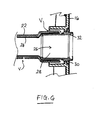
- the tube 12 is coupled to the support coupling 16 by a flanged adapter tube 26.
- the adapter tube 26 generally comprises a tubular spigot 28 with locating flanges 30 and a mouth section 32.
- the tubular spigot 28 is inserted into the proximal end of the first tube member 22 to affix to the proximal end of the first tube member 22 either by adhesive or by a tight friction fit.
- the adapter tube 26 is secured to the support coupling 16 by means of the locating flanges 30 which interlock against the support coupling 16.
- the second tube (sleeve) member 24 is configured to extend longitudinally beyond the proximal end of the first tube member 22, and to pass inside the adapter tube 26 to define a protruding portion 24a that protrudes slightly from the mouth section 32 and the support coupling 16.
- the portion of the second tube (sleeve) member 24 inside the adapter tube 26 is optionally secured to the adapter tube 26, for example, by adhesive, welding or the introduction of an inner ring (shown in phantom at 26a) to trap the film against the inside of the adapter tube.
- the protruding portion 24a fits just inside the aperture of a fecal collection container that is secured to the support coupling 16, to thereby provide a continuous odor barrier from the tube 12, through the adapter tube 26 and support coupling 16 into the fecal collection chamber.
- the protruding portion 24a of the second tube member 24 is folded back around the locating flanges 30 of the adapter tube 26, so as to be trapped between the locating flanges 30 and the support connector 16 when the adapter tube 26 is fitted to the support connector 16. With this configuration, no adhesive is necessary at the proximal end of the tube 12 to fasten the proximal end of the second tube member 24.
- the proximal end of the second tube member 24 again passes inside the adapter tube 26, but is dimensioned not to protrude from the mouth section 32.
- the proximal end of the second tube member 24 is secured to the inner surface of the adapter tube 26, for example, by adhesive, welding or the introduction of an inner ring 26a to trap the film against the inside of the adapter tube.
- the proximal end of the second tube member 24 is not passed inside the adapter tube 26, but instead is passed over the outer surface of the tubular spigot 28 and trapped between the spigot 28 and the proximal end of the first tube member 22.
- the second tube member (odor barrier sleeve) 24 is provided as an external sleeve around the first (silicone) tube member 22.
- a feature of an external sleeve is that the second tube member 24 does not occupy any of the internal space of the first tube member 22.
- the second tube member 24 closely conforms to the size of the first tube member 22. This is achieved by using a heat shrinkable material for the second tube member 22.
- plastics film having both heat shrinkable properties and odor barrier properties based on ethylene vinyl alcohol copolymers (EVOH) or poly(vinylidene chloride) (PVDC) is available from Cryovac and Perfecseal.
- the odor barrier is reported to be between 4-50 cc/m 2 /day at 23°C, and the shrink property is reported to be at least 10%, preferably at least 30% at 100°C.
- the plastics film is made into a tube slightly larger in diameter than the first tube member 22. For example, if the outer diameter of the first tube member 22 is about 2.2 cm, then film for the second tube member 24 may be formed into a tube of about 2.5-3.0 cm in diameter. The second tube member 24 is then slid over the first tube member 22, and is heated to shrink down tightly around the surface of the first tube member 22. Any air or other gas trapped between the two tube members 22 and 24 may vent through one or more small vent paths.
- shrinking down the second tube member 24 on to the first tube member 22 can avoid the need for adhesive attachment, but desired adhesive attachment may be used to reinforce the anchoring of the second tube member 24 around the first tube member 22.
- the second tube member 24 can also fit loosely outside of the first tube member 22, and can be attached to each other at or near at least one end or both ends.
- an odor barrier tube member distinct from the silicone tube member
- another way of incorporating an odor barrier material into a silicone tube is by adding, either extrusion, coextrusion, or adhesive lamination, the odor barrier material to the silicone tube.
- the odor barrier layer could be as an exterior layer or a surface layer or in the middle of the silicone tube.
- an adhesive layer is provided to enhance the adhesion between odor material layer and silicone.
- the introduction of the odor barrier layer could be during silicone tube extrusion, for example coextrusion. Or the process can take place after the silicone extrusion, for example, extrusion coating or adhesive lamination.
- the odor barrier could be incorporated into a silicone sheet using adhesives and then the sheet converted into a tube form.
- Figs. 9 and 10 illustrate a third embodiment in which the tube 12 comprises a single tube member 40.
- the wall of the tube member 40 is a laminate comprising at least one layer 42 of silicone based material and at least one layer 44 of odor barrier material.
- the odor barrier material may be any of the examples described hereinbefore.
- the laminate may optionally include one or more adhesive layers 46 for bonding the odor barrier material to the silicone based material.
- the odor barrier layer 44 is provided at a surface portion of the tubing 40. The surface portion may be at the radially outer surface, or the radially inner surface.
- the odor barrier layer 44 is sandwiched in the middle of inner and outer layers 42 of silicone based material.
- the layers 42 of silicone material on either side of the odor barrier layer 44 may be of about the same thickness, one layer 42 may be thicker than the other.
Abstract
Description
- The present invention relates to a silicone based tube for transporting malodoriferous matter from the human body. The tube may, for example, be used in bowel management apparatus for hygienically collecting fecal matter from the human body, but the invention may find use in any system for transporting malodoriferous matter from the human body.
-
US 2005/0054996 andUS 2005/0137526 describe bowel management apparatus including a silicone tube having at its distal end a balloon cuff that may be inflated to locate the distal end of the tube inside a wearer's rectum. The proximal end of the tube is fitted with a connector for making a connection to a fecal collector chamber. It is difficult to find an ideal single material that exhibits all of the desired characteristics for making the tube. Silicone is used for its biocompatibility, flexibility and comfortable wear characteristics. However, silicone is known to have a relatively high gas transpiration (or transmission) rate, which might lead to malodors leaking through the material forming the tube, especially if the tube has a relatively long run to the fecal collection chamber. The human nose is especially sensitive to flatus, and foul odors are embarrassing and unpleasant for the wearer and caregivers. - In
US 2005/0054996 , a parylene coating is applied to the surfaces of the silicone material to improve its odor barrier properties. However, in some cases, the parylene coating might not be ideal because: - (i) the parylene coating tends to be highly crystalline, and so might be vulnerable to micro-cracking when the silicone tube is flexed or twisted or stretched in use, leading possibly to a reduction in the integrity of the odor barrier;
- (ii) the parylene coating tends to be relatively thin. Any irregularities in the deposited thin coating could further risk the integrity of the odor barrier. For example, the odor barrier of parylene at 25 µm thickness is reported to be 30 cc/m2/day at 23°C. However, a thin coating in the range of 1-2 µm thickness could result in an oxygen transmission rate much higher, in the 380-760 cc/m2/day range, which might be too high to provide sufficient odor barrier. Any micro-cracking in parylene would even worsen already compromised thin layer of barrier coating;
- (iii) the coating process involves polymerizing and vacuum depositing the parylene onto the silicone tube, which is a difficult and expensive manufacturing process, thus increasing the manufacturing costs; and
- (iv) there is a requirement to mask some key parts of the device against coating by parylene, which further complicates the manufacturing process;
- For reference, other bowel and stoma appliances employing silicone based tubes include
U.S. Patent Nos. 4381765 ,4662890 ,4721508 and5569216 , and publishedU.S. Patent Applications 2004/0039348 ,2006/0100595 and2006/0189951 . However, none of these publications address the issue of odor leakage through the silicone material. - The present invention has been directed to enhancing the characteristics of the silicone tube for handling malodoriferous matter. In particular, it would be desirable to provide an alternative odor barrier technique for the silicone tube, which can achieve at least approximately the same degree of odor barrier as a parylene coating, but which may be less disadvantageous.
- Broadly speaking, one aspect of the invention is to provide a silicone tube with an inner and/or outer tubular sleeve member, the tubular sleeve member comprising an odor barrier material.
- The term odor barrier material is intended to include any material that has a greater resistance to transmission or permeation of odors, than silicone, preferably at least an order of magnitude greater. The invention can significantly enhance the odor barrier properties of the silicone tube by at least slowing down, or preferably substantially stopping, permeation of unpleasant odors from the silicone tube. Moreover, the provision of a distinct sleeve member inside or outside the silicone tube can avoid the problems associated with chemically depositing a thin film coating on the silicone. In particular, it can avoid the need for complex and expensive deposition processes, and it can avoid the issues of the thickness and integrity of the deposited film.
- Preferably, the sleeve member is flexible, in order not to hinder bending of the silicone tube. Preferably the sleeve member is as flexible as the silicone tube and ideally more flexible than the silicone tube.
- Preferably the wall thickness of the sleeve member is less than that of the silicone tube, in order not to increase substantially the size of the tubing and/or not to decrease the bore size of the internal passage inside the silicone tube. Preferably, the wall thickness of the sleeve member is not more than about 1/10 of that of the silicone tube.
- In one form, the sleeve member is made of flexible film material. A suitable material is, for example, the flexible film conventionally used for the production of ostomy pouches and urine pouches. The film may be a laminate including the odor barrier material layer and one or more non-odor barrier materials. It is also possible to have a homogenous film, such as nylon, to bond well to silicone by adhesive and to block odor transmission. The film may be extruded in a sleeve shape, or the sleeve may be formed from sheet form by wrapping the sheet into a closed loop sleeve shape and sealing the edges together to form a longitudinal seam. If desired, the sheet may be rolled to form a sleeve of several layers before sealing.
- In one form, the sleeve member is fitted outside the silicone tube. The sleeve is secured in place by any suitable means. Placing the sleeve outside the tube avoids the need to support the sleeve internally, since the shape of the sleeve is determined by the silicone tube. An especially preferred technique is to provide a sleeve made of material that shrinks when subjected to heat, and to heat the sleeve in order to shrink the sleeve around the silicone tube. This can provide firm anchoring of the sleeve around the silicone tube, without having to use any additional fastening device or adhesive. Alternatively, the sleeve may made slightly larger than the silicone tube, and the sleeve may be fed over the silicone tube, and fastened in position either by adhesive or by a mechanical fastening. Alternatively, the sleeve may be formed from sheet material wrapped around the silicone tube.
- In another form, the tubular sleeve member comprises an inner liner fitted inside the silicone tube. The inner liner is preferably secured in place by adhesive and/or by a mechanical device, to ensure that the liner is not displaced axially in use. Axial displacement could dislodge the liner, removing the odor barrier protection from a local area. The inner liner may be secured only at its ends if desired.
- A vent path may be provided for gas in the space between the silicone tube and the tubular sleeve member. The vent path may avoid gas collecting between the two tubes, which otherwise might cause undesirable ballooning of the collection bag or constricting of the waste path. Gas could enter the space between the tubes during manufacture, or during transportation, or during use of the tube. Preferably, the vent path vents into a region communicating with a flatus filter or it may vent into the collection volume for the fecal matter. If the sleeve member is on the inside of the silicone tube and creates a seal with the collection volume, the venting can be directly to atmosphere.
- A further independent, yet closely related, aspect of the invention is to provide a tube made of a laminate comprising a layer of silicone based material, and a layer of odor barrier material. These layers are laminated together either prior to, or at the same time as, the formation of the silicone based material into a tubular form. The layer of odor barrier material may be provided either as a surface layer or a non-surface layer of the laminate.
- A further independent, yet closely related, aspect of the invention is to produce a tube including a layer of silicone based material and a layer of odor barrier material by at least one of the following processes: extrusion, coextrusion, extrusion coating, or adhesive lamination.
- The step of forming may optionally comprise at least one of the following processes: extrusion, coextrusion, extrusion coating, or adhesive lamination.
- These aspects of the invention results in a single tube member incorporating both the silicone based material and the odor barrier material laminated together. This aspect also avoids the problems in the prior art associated with chemically depositing a thin film coating on the silicone. In particular, it can avoid the need for complex and expensive deposition processes, and it can avoid the issues of the thickness and integrity of the deposited film.
- A further aspect provides a silicone based tube provided with a layer of odor barrier material for obstructing leakage of odors from material carried inside the tube. Preferably, the barrier material comprises at least one selected from: poly(vinylidene chloride) (PVDC); poly(vinyl alcohol) (PVOH); an ethylene vinyl alcohol copolymer (EVOH); a polyamide (nylon) or co-polyamide or polyamide blends selected from PA-6, PA-6,6, PA-11, and PA-12, amorphous polyamides, MXD6 polyamide; a polyester (PET); a polyester elastomer; glycol-modified polyester (PETG); a polyester or co-polyester blend; poly(acrylonitrile) (PAN); polyurethane (PUR); polyvinyl chloride (PVC); polychlorotrifluoro ethylene (PCTFE); styrene-acrylonitrile copolymers; acrylonitrile-butadiene-styrene terpolymers; poly(methyl methacrylate); styrene-butadiene copolymers.
- Other features and advantages of the present invention will be apparent from the following description of preferred embodiments.
-
-
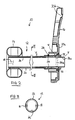
Fig. 1 is a perspective view of a first embodiment of a bowel management apparatus. -
Fig. 2 is a cross-sectional view of the first embodiment. -
Fig. 3 is cross-sectional view along the line III-III ofFig. 2 . -
Fig. 4 is a cross-sectional view showing a modification of the first embodiment, with a different proximal end arrangement. -
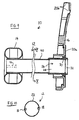
Fig. 5 is a cross-sectional view showing a further modification of the first embodiment, with a different proximal end arrangement. -
Fig. 6 is a cross-sectional view showing a further modification of the first embodiment, with a different proximal end arrangement. -
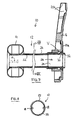
Fig. 7 is a cross-sectional view showing a second embodiment. -
Fig. 8 is a view along the line VIII-VIII ofFig. 7 . -
Fig. 9 is a cross-sectional view through a wall portion of the tube in a third embodiment. -
Fig. 10 is view along the line X-X ofFig. 9 . -
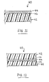
Fig. 11 is a schematic cross-sectional view showing a wall portion of the tube of the third embodiment. -
Fig. 12 is a schematic cross-sectional view showing a modified form of wall portion of the tube of the third embodiment. - Referring to
Fig. 1 , abowel management apparatus 10 generally comprises atube 12 at the distal end of which is provided anannular balloon cuff 14, and at the proximal end is provided asupport connector 16. The distal end is for insertion into the rectum of a wearer, for example a bedbound person. Theballoon cuff 14 is inflatable via aninflation conduit 18 for retaining the distal end in the rectum. Thetube 12 functions to hygienically transport excreted stool and flatus from the body to a fecal collection container (not shown), such as a fecal bag. Thesupport connector 16 provides a connection point to the fecal collection container and an attachment point for attaching to the person's bed. In the current embodiment, thesupport connector 16 comprises anannular landing zone 20a for adhesive attachment to the fecal collection container or an injection molded flange for mechanically coupling to the fecal collection container, and anaperture 20b for receiving an attaching strap (not shown). - The
tube 12 may be of any desired length, for example from about a few centimeters (e.g., the minimum distance for the tube to exit the rectum to at least the exterior skin surface), up to the order of 1 - 2 meters or more (e.g., to provide a tube length sufficient to reach the edge of a bed while still allowing the wearer to move around in the bed). In the illustrated form, thetube 12 consists of a single length of material, but the invention envisages that thetube 12 could be made of plural tube segments. - Referring to
Fig. 2 , thetube 12 generally comprises afirst tube member 22 and asecond tube member 24 placed one within the other. Thefirst tube member 22 is a primary shape defining tube made of a silicone material, for example, silicone rubber. Silicone is chosen for its biocompatibility, flexibility and comfort characteristics. Thefirst tube member 22 is soft enough to enable the tube to be flexible and conformable, while being sufficiently stiff to retain an open tubular shape when not compressed. In the present embodiment, thefirst tube member 22 has a generally round cross-section shape, with an outer diameter of about 2-4 cm, and a wall thickness of between about 0.25 and 5 mm. Thesecond tube member 24 is an odor barrier sleeve comprising an odor barrier material. The odor barrier material has a greater resistance to transmission or permeation of odors, than silicone, preferably at least an order of magnitude greater. Thesecond tube member 24 is generally as flexible as thefirst tube member 22 so as not to obstruct the flexibility of thetube 12. Thesecond tube member 24 has a thinner wall thickness than thefirst tube 22, for example, not more than about 1/10 of the wall thickness of thefirst tube 22. Generally, in such a thin and flexible film, thesecond tube member 24 might not retain an open tubular shape itself, but instead, thesecond tube member 24 is supported by thefirst tube member 22 to the extent necessary. - The provision of the
second tube member 24 can greatly enhance the odor barrier properties of thetube 12 compared to just thesilicone tube member 22 alone. Although the characteristics of silicone material of thefirst tube member 22 are excellent in many respects, one area where silicone lacks performance is its odor barrier characteristics. Odor leakage may be especially noticeable in longer tube lengths but may also be evident in shorter lengths. The invention can significantly enhance the odor barrier properties of both long (e.g., more than about 50cm, or more than 100cm), and short silicone tubes by at least slowing down, or preferably substantially stopping, permeation of unpleasant odors from the silicone tube. Moreover, the provision of the odor barrier as a distinct sleeve member can avoid the problems associated with chemically depositing a thin film coating on the silicone. In particular, it can avoid micro-cracking of the coating and the need for complex and expensive deposition processes, and it can avoid the issues of the thickness and integrity of the deposited film. Generally, thesecond tube member 24 will retain its full integrity throughout the use life of the siliconefirst tube member 22, even with repeated flexing, stretching and twisting of thetube 12 in its normal everyday use. - Any suitable material with odor barrier properties may be used for the
second tube 24. One preferred example is plastics film conventionally used for manufacturing ostomy pouches. Such plastics film is relatively inexpensive, strong, has good workability (e.g., with adhesives or welding), known biocompatibility and excellent odor barrier properties. An example plastics film comprises an odor barrier of poly(vinylidene chloride) (PVDC). Such a barrier polymer can be coextruded or laminated with one of more layers of ethylene vinyl acetate (EVA). Another preferred example is nylon film, which provides good odor barrier properties and provides a good adhesive bond to silicone. Other examples of odor barrier materials include poly(vinyl alcohol) (PVOH), ethylene vinyl alcohol copolymers (EVOH), a polyamide or co-polyamide or polyamide blends selected from PA-6, PA-6,6, PA-11, and PA-12, amorphous polyamides, MXD6 polyamide, polyesters (PET), polyester elastomers, glycol-modified polyester (PETG), a polyester or co-polyester blend, poly(acrylonitrile) (PAN), polyurethane (PUR), polyvinyl chloride (PVC), fluoropolymers such as polychlorotrifluoro ethylene (PCTFE), styrene-acrylonitrile copolymers, acrylonitrile-butadiene-styrene terpolymers, poly(methyl methacrylate), styrene-butadiene copolymers, polyacrylonitrile, and homopolymers, copolymers, or blends of above polymers. - The plastics film may be extruded in the tubular sleeve shape, or a sheet of the film material may be rolled around a former and secured in its rolled up form, for example, by adhesive or by a welded seam. The sleeve may comprise a single layer of film, a multilayer film, cross wound tube, or the film may be rolled on itself several times.
- The following description describes two alternative embodiments, a first in which the second tube member (odor barrier sleeve) 24 is fitted inside the
first tube member 22; and a second embodiment in which the second tube member (odor barrier sleeve) 24 is fitted outside thesecond tube member 22. The following table illustrates the comparative performance of both embodiments compared to a silicone tube without any odor barrier, and a silicone tube with a parylene coating, by using the so-called "Onion Test" (British Standard 7127: Part 101: 1991) in which the odor barrier properties are assessed according to whether odor from an onion when contained by the test material in a closed system can be detected by the human nose. Films were also tested for their odor barrier using oxygen transmission rate (OTR), ASTM D3985:Emb. TUBE TYPE Oxygen Transmission Rate (OTR), cc/m2/day at 23°C, 90%RH ONION TEST Silicone tube without odor barrier 40,000 Very Strong smell Silicone tube with parylene coating > 6,000 Strong smell 1 Silicone tube with inner odor barrier sleeve of PVdC-containing film 50 No smell detected 1 Silicone tube with inner odor barrier sleeve of nylon film 100 No smell detected 2 Silicone tube with outer odor barrier sleeve made of shrinkable EVOH-containing barrier film 50 No smell detected - Oxygen transmission rate (OTR) is used as a reasonable predictor of the device's low permeability to the smaller odorous molecules in human fecal matter, while onion test is used as an overall predictor of the device's resistance to the permeation of malodoriferous compounds generated from the digestive system in the human body.
- As noted in the table, silicone tubing without odor barrier had an extremely high OTR of around 40,000 cc/m2/day, and did not provide any resistance against onion odor. Although the parylene coating of silicone tube used in the prior art had better OTR than that of silicone tube without odor barrier material, the level of OTR was still considered high at around 6,000 cc/m2/day and did not provide sufficient barrier against onion odor. In all three examples according to the invention, the use of tubular sleeve materials significantly reduced OTR to a range less than 1,000 cc/m2/day and preferably less than 500 cc/m2/day. As shown in the table, all three examples offered great resistance against onion odor.
- Although not tested, the invention also encompasses the possibility of providing odor barrier sleeve members both inside and outside the silicone tube. However, it is currently believed that such a combination is not essential, since the above tests illustrate that a single odor barrier sleeve member, either inside or outside the silicone tube provides excellent odor barrier performance. The choice depends on the desired production techniques and the desired properties of the
tube 12 depending on a specific application in use. - In the first embodiment illustrated in
Figs. 2 and 3 , the second tube (sleeve)member 24 is provided as an internal liner inside thefirst tube member 22. Thesecond tube member 24 is fastened to thefirst tube member 22, for example, completely around its circumference at the distal end (i.e., patient end) and substantially along its entire length, or at least at longitudinally and/or circumferentially spaced apart positions, or at least one longitudinal position. The attachment may be by means of adhesive. The attachment serves to create a seal between the first and second tubes at the patient end and locate thesecond tube member 24 axially, in order to prevent thesecond tube member 24 from being dislodged or displaced axially, for example by passage of fecal matter within thetube 12, or if thetube 12 is milked by a caregiver to peristaltically advance fecal matter along thetube 12. The fastening may optionally support thesecond tube member 24 and thus keeps the tubular space generally open and unobstructed by preventing the second tube member from collapsing inside thefirst tube member 22. However, in the preferred embodiment, thesecond tube member 24 is fastened only at or near one or both ends thereof. - In the case where the
second tube member 24 is not fastened to thefirst tube member 22 along its entire length, a vent path "V" is provided for allowing any gas trapped between the first andsecond tuber members second tube members first tube member 22. Generally, it is desired to allow such gas to vent away easily, so as to avoid constricting the internal bore inside the first andsecond tube members tube 12. - An example material for the
second tube member 24 is a 75 µm thick PVdC-containing film from Cryovac. Another preferred example is nylon film. Thesecond tube member 24 may have a diameter slightly smaller than thefirst tube member 22, for example about 1.9 cm, or slightly bigger than thefirst tube member 22, for example about 2.13 cm. The film may be attached in position by any suitable adhesive, for example, a two-part silicone adhesive by Nusil Technology, a RTV silicone adhesive made by CRC Industries, Inc. - The
tube 12 may be made by forming the first andsecond tube members second tube member 24 inside the first, and advancing one tube member relative to the other, to draw thesecond tube member 24 to extend completely through thefirst tube member 22. - Within the
first tube member 22, thesecond tube member 24 sits radially inwardly of anysecondary conduits 18 carried by thefirst tube member 22, such as theinflation conduit 18 mentioned above, and/or an irrigation conduit for irrigating the rectum. Such an arrangement can allow an external fluid connection to be made through the wall of thefirst tube member 22 to thesecondary conduit 18, without breaching thesecond tube member 24, and thus without breaching the integrity of the odor barrier. This arrangement is especially suitable when thesecondary conduit 18 is integrally formed with, or is attached to, the wall of thefirst tube member 22. Alternatively, in a modified form not shown, if thesecondary conduit 18 is a separate conduit not integrally attached to thefirst tube member 22, then thesecondary conduit 18 could run inside the bore of thesecond tube member 24 if desired. - As can be seen in
Fig. 2 , thetube 12 is coupled to thesupport coupling 16 by aflanged adapter tube 26. Theadapter tube 26 generally comprises atubular spigot 28 with locatingflanges 30 and amouth section 32. In use, thetubular spigot 28 is inserted into the proximal end of thefirst tube member 22 to affix to the proximal end of thefirst tube member 22 either by adhesive or by a tight friction fit. Theadapter tube 26 is secured to thesupport coupling 16 by means of the locatingflanges 30 which interlock against thesupport coupling 16. - In the first embodiment, the second tube (sleeve)
member 24 is configured to extend longitudinally beyond the proximal end of thefirst tube member 22, and to pass inside theadapter tube 26 to define a protruding portion 24a that protrudes slightly from themouth section 32 and thesupport coupling 16. The portion of the second tube (sleeve)member 24 inside theadapter tube 26 is optionally secured to theadapter tube 26, for example, by adhesive, welding or the introduction of an inner ring (shown in phantom at 26a) to trap the film against the inside of the adapter tube. In use, the protruding portion 24a fits just inside the aperture of a fecal collection container that is secured to thesupport coupling 16, to thereby provide a continuous odor barrier from thetube 12, through theadapter tube 26 andsupport coupling 16 into the fecal collection chamber. - In a modified form of the first embodiment illustrated in
Fig. 4 , the protruding portion 24a of thesecond tube member 24 is folded back around the locatingflanges 30 of theadapter tube 26, so as to be trapped between the locatingflanges 30 and thesupport connector 16 when theadapter tube 26 is fitted to thesupport connector 16. With this configuration, no adhesive is necessary at the proximal end of thetube 12 to fasten the proximal end of thesecond tube member 24. - In a further modified form of the first embodiment illustrated in
Fig. 5 , the proximal end of thesecond tube member 24 again passes inside theadapter tube 26, but is dimensioned not to protrude from themouth section 32. The proximal end of thesecond tube member 24 is secured to the inner surface of theadapter tube 26, for example, by adhesive, welding or the introduction of aninner ring 26a to trap the film against the inside of the adapter tube.. - In a further modified form of the first embodiment illustrated in
Fig. 6 , the proximal end of thesecond tube member 24 is not passed inside theadapter tube 26, but instead is passed over the outer surface of thetubular spigot 28 and trapped between thespigot 28 and the proximal end of thefirst tube member 22. - In the second embodiment illustrated in
Figs. 7 and 8 , the second tube member (odor barrier sleeve) 24 is provided as an external sleeve around the first (silicone)tube member 22. A feature of an external sleeve is that thesecond tube member 24 does not occupy any of the internal space of thefirst tube member 22. In the illustrated form, thesecond tube member 24 closely conforms to the size of thefirst tube member 22. This is achieved by using a heat shrinkable material for thesecond tube member 22. For example, plastics film having both heat shrinkable properties and odor barrier properties based on ethylene vinyl alcohol copolymers (EVOH) or poly(vinylidene chloride) (PVDC) is available from Cryovac and Perfecseal. The odor barrier is reported to be between 4-50 cc/m2/day at 23°C, and the shrink property is reported to be at least 10%, preferably at least 30% at 100°C. The plastics film is made into a tube slightly larger in diameter than thefirst tube member 22. For example, if the outer diameter of thefirst tube member 22 is about 2.2 cm, then film for thesecond tube member 24 may be formed into a tube of about 2.5-3.0 cm in diameter. Thesecond tube member 24 is then slid over thefirst tube member 22, and is heated to shrink down tightly around the surface of thefirst tube member 22. Any air or other gas trapped between the twotube members second tube member 24 on to thefirst tube member 22 can avoid the need for adhesive attachment, but desired adhesive attachment may be used to reinforce the anchoring of thesecond tube member 24 around thefirst tube member 22. Optionally, thesecond tube member 24 can also fit loosely outside of thefirst tube member 22, and can be attached to each other at or near at least one end or both ends. - In addition to, or as an alternative to, the use of an odor barrier tube member distinct from the silicone tube member, another way of incorporating an odor barrier material into a silicone tube is by adding, either extrusion, coextrusion, or adhesive lamination, the odor barrier material to the silicone tube. The odor barrier layer could be as an exterior layer or a surface layer or in the middle of the silicone tube. Optionally, an adhesive layer is provided to enhance the adhesion between odor material layer and silicone. The introduction of the odor barrier layer could be during silicone tube extrusion, for example coextrusion. Or the process can take place after the silicone extrusion, for example, extrusion coating or adhesive lamination. Optionally, the odor barrier could be incorporated into a silicone sheet using adhesives and then the sheet converted into a tube form.
-
Figs. 9 and 10 illustrate a third embodiment in which thetube 12 comprises asingle tube member 40. Referring toFigs. 11 and 12 , the wall of thetube member 40 is a laminate comprising at least onelayer 42 of silicone based material and at least onelayer 44 of odor barrier material. The odor barrier material may be any of the examples described hereinbefore. As indicated in phantom, the laminate may optionally include one or moreadhesive layers 46 for bonding the odor barrier material to the silicone based material. In the example shown inFig. 11 , theodor barrier layer 44 is provided at a surface portion of thetubing 40. The surface portion may be at the radially outer surface, or the radially inner surface. In the example shown inFig. 12 , theodor barrier layer 44 is sandwiched in the middle of inner andouter layers 42 of silicone based material. Thelayers 42 of silicone material on either side of theodor barrier layer 44 may be of about the same thickness, onelayer 42 may be thicker than the other. - It will be appreciated that the foregoing description is illustrative of preferred embodiments of the invention as defined in the dependent claims. Improvements may be made without departing from the claim coverage of the invention.
Claims (14)
- A tubular bowel management assembly (10) for carrying malodoriforous matter from the rectum, the tubular bowel management assembly (10) comprising:(a) a silicone based tube (22) having a central bore for the malodoriforous matter, said tube (22) having a distal end insertable into and retainable within the rectum, said tube (22) extending externally of the rectum for conveying the malodorous matter from the body;(b) a distinct tubular sleeve member (24) comprising an odor barrier material, the odor barrier material having a greater resistance to transmission of gas than that of the silicone based tube ; and(c) the silicone based tube (22) and tubular sleeve member (24) being arranged one within the other such that the tubular sleeve member (24)provides an odor barrier to obstruct leakage of odors from malodoriforous matter in the bore of the silicone based tube(22).
- The tubular bowel management assembly (10)according to claim 1, wherein the tubular sleeve member has an oxygen transmission rate (OTR) no more than 1,000 cc/m2/day at 23°C.
- The tubular bowel management assembly (10) according to any preceding claim, wherein the tubular sleeve member (24) is arranged inside the silicone based tube.
- The tubular bowel management assembly (10) according to any of claims 1 to 2, wherein the tubular sleeve member is arranged outside the silicone based tube.
- The tubular bowel management assembly (10) according to any preceding claim, wherein the tubular sleeve member (24) has a thinner wall thickness than that of the silicone based tube (22).
- The tubular bowel management assembly (10) according to any preceding claim, wherein at least a portion of the tubular sleeve member (24) is fastened to the silicone based tube (22).
- The tubular bowel management assembly (10) according to any preceding claim, wherein said portion is fastened by using at least one of the following:adhesive; 2-part heat cure silicone adhesive; RTV silicone sealant; mechanical force; temperature; pressure.
- The tubular bowel management assembly (10) according to claim 6 or 7, wherein said portion of the tubular sleeve member (24) is fastened at least at one end.
- The tubular bowel management assembly (10) according to any preceding claim, further comprising an adapter tube (26) disposed at a first end of the silicone based tube, and wherein the tubular sleeve member (24) is fastened to the adapter tube (26).
- The tubular bowel management assembly (10) according to any preceding claim, wherein the tubular sleeve member (24) is selected from: a seamless tubular film; sheet material rolled into a tubular shape.
- The tubular bowel management assembly (10) according to claim 1, wherein the tubular sleeve member (24) is made of a multi-layer firm, the multi-layer film including said odor barrier material which is at least one selected from:poly(vinylidene chloride) (PVDC); poly(vinyl alcohol) (PVOH); an ethylene vinyl alcohol copolymer (EVOH); a polyamide (nylon) or co-polyamide or polyamide blends selected from PA-6, PA-6,6, PA-11, and PA-12, amorphous polyamides, MXD6 polyamide; a polyester (PET); a polyester elastomer; a glycol-modified polyester (PETG); a polyester or co-polyester blend; a poly(acrylontrile) (PAN); a polyurethane (PUR); a polyvinylchloride (PVC); a polychlorotrifluoro ethylene (PCTFP); a styrene-acrylonitrile copolymer; a acrylonitrile-butdiene-styrene terpolymer; a poly(methyl methacrylate); a styrene-butadiene copolymer.
- A tubular bowel management assembly (10) for carrying malodoriforous matter from the rectum, a tube (40) being made of a laminate material comprising:(a) a layer of silicone based material (42); and(b) a layer of an odor barrier material (44) laminated with the silicone based material (42) to obstruct leakage of odors from malodoriforous matter in said tube (40);wherein the laminate material is such that the odor barrier material (44) is laminated with the silicone based material (42) prior to, or at the time of, formation of the silicone based material (42) into a tube, said tube having a distal end insertable into and retainable within the rectum, said tube being predeterminedly dimensioned to extend externally of the rectum.
- The tubular bowel management assembly (10) according to claim 12, further comprising an adhesive layer (46) for bonding the layer of odor barrier material (44) to the layer of silicone based material (42).
- The tubular bowel management assembly (10) of any of claims 1 to 10, 12 and 13 wherein the odor barrier material comprises at least one selected from:poly(vinylidene chloride) (PVDC); poly(vinyl alcohol) (PVOH); an ethylene vinyl alcohol copolymer (EVOH); a polyamide (nylon) or co-polyamide or polyamide blends selected from PA-6, PA-6,6, PA-11, and PA-12, amorphous polyamides,MXD6 polyamide; a polyester (PET); a polyester elastomer; a glycol-modified polyester (PETG); a polyester or co-polyester blend; a poly(acrylontrile) (PAN);a polyurethane (PUR); a polyvinylchloride (PVC); a polychlorotrifluoro ethylene (PCTFE); a styrene-acrylonitrile copolymer; a acrylonitrile-butdiene-styrene terpolymer; a poly(methyl methacrylate); a styrene-butadiene copolymer
Applications Claiming Priority (2)
| Application Number | Priority Date | Filing Date | Title |
|---|---|---|---|
| US86305306P | 2006-10-26 | 2006-10-26 | |
| PCT/US2007/082312 WO2008052018A2 (en) | 2006-10-26 | 2007-10-24 | Silicone based tube for transporting malodoriforous matter from the human body |
Publications (3)
| Publication Number | Publication Date |
|---|---|
| EP2104478A2 EP2104478A2 (en) | 2009-09-30 |
| EP2104478A4 EP2104478A4 (en) | 2012-01-25 |
| EP2104478B1 true EP2104478B1 (en) | 2013-11-20 |
Family
ID=39325363
Family Applications (1)
| Application Number | Title | Priority Date | Filing Date |
|---|---|---|---|
| EP07863463.1A Active EP2104478B1 (en) | 2006-10-26 | 2007-10-24 | Silicone based tube for transporting malodoriforous matter from the human body |
Country Status (11)
| Country | Link |
|---|---|
| US (1) | US8323254B2 (en) |
| EP (1) | EP2104478B1 (en) |
| JP (1) | JP5624321B2 (en) |
| CN (1) | CN101557780B (en) |
| AU (1) | AU2007308971B2 (en) |
| BR (1) | BRPI0717337A2 (en) |
| CA (1) | CA2667822C (en) |
| MX (1) | MX2009004184A (en) |
| NZ (1) | NZ577154A (en) |
| RU (1) | RU2454976C2 (en) |
| WO (1) | WO2008052018A2 (en) |
Families Citing this family (22)
| Publication number | Priority date | Publication date | Assignee | Title |
|---|---|---|---|---|
| US8936583B2 (en) | 2007-09-28 | 2015-01-20 | Hollister Incorporated | Multi-layer catheter tubes with odor barrier |
| WO2009045874A1 (en) * | 2007-09-28 | 2009-04-09 | Hollister Incorporated | Multi-layer odor barrier tube, and combination odor barrier tube and odor barrier collection bag |
| US8795234B2 (en) | 2010-11-30 | 2014-08-05 | Becton, Dickinson And Company | Integrated spring-activated ballistic insertion for drug infusion device |
| WO2013109293A1 (en) | 2011-02-17 | 2013-07-25 | Convatec Technologies Inc. | Valve system for inflatable medical device |
| JP6224460B2 (en) * | 2011-03-17 | 2017-11-01 | コンバテック・テクノロジーズ・インコーポレイテッドConvatec Technologies Inc | High barrier elastomer fecal catheter or ostomy pouch |
| GB201115160D0 (en) | 2011-09-02 | 2011-10-19 | Trio Healthcare Ltd | Discharge solidifier and malodour control |
| MX347628B (en) | 2011-11-16 | 2017-05-04 | Convatec Technologies Inc | Apparatus for preventing over inflation of the retention balloon in medical catheters and airway devices. |
| DK2620168T3 (en) * | 2012-01-27 | 2020-06-02 | Hollister Inc | MULTI-LAYER CATTLE HOSE WITH AIR BARRIER |
| CN114288545A (en) | 2013-08-01 | 2022-04-08 | 康沃特克科技公司 | Self-closing bag connector |
| US20150100033A1 (en) * | 2013-10-03 | 2015-04-09 | Kristopher Mark Weide | Semi-rigid device for sealing and allowing continuous drainage of colostomy bags |
| KR101639012B1 (en) * | 2013-12-19 | 2016-07-14 | 경북대학교 산학협력단 | A Device for Protecting the Rectal Anastomosis |
| TW201709946A (en) | 2015-05-18 | 2017-03-16 | 康瓦鐵克科技股份有限公司 | Spring-loaded bag connector |
| JP7018389B2 (en) | 2015-10-29 | 2022-02-10 | コンバテック・テクノロジーズ・インコーポレイテッド | Inflatable device valve system |
| AU2016349486B2 (en) * | 2015-11-06 | 2021-02-04 | Avent, Inc. | Ostomy device, apparatus, and system |
| CN110177690A (en) * | 2016-10-14 | 2019-08-27 | 克里奥瓦克公司 | Packaging film for sensory sensitive products, method thereof, packaging product and packaging product |
| RU183249U1 (en) * | 2017-12-22 | 2018-09-14 | Доброслав Викторович Ударцев | DEVICE FOR GAS EXHAUST AND GAS DRAINAGE |
| US11583432B2 (en) | 2017-12-22 | 2023-02-21 | Dobroslav Viktorovich UDARTSEV | Device for discharge and collection of intestinal gases |
| CN111615374B (en) | 2018-01-19 | 2023-09-01 | 科洛普拉斯特公司 | System for applying an ostomy covering |
| RU184950U1 (en) * | 2018-02-28 | 2018-11-15 | Доброслав Викторович Ударцев | GAS PUMP |
| WO2019168433A1 (en) * | 2018-02-28 | 2019-09-06 | Доброслав Викторович УДАРЦЕВ | Gas collector |
| RU2683849C1 (en) * | 2018-07-30 | 2019-04-02 | Владимир Александрович Парамошко | Method for voiding |
| DE102020002764A1 (en) * | 2020-04-28 | 2021-10-28 | Advanced Medical Balloons Gmbh | Device for the medical discharge and supply of substances with odor-reducing properties and their cost-effective production |
Family Cites Families (19)
| Publication number | Priority date | Publication date | Assignee | Title |
|---|---|---|---|---|
| US4381765A (en) | 1981-04-02 | 1983-05-03 | Waters Instruments, Inc. | Ileostomy valve |
| SU1199245A1 (en) * | 1984-05-14 | 1985-12-23 | Всесоюзный научно-исследовательский институт текстильно-галантерейной промышленности | Deodorant spacer for patients ill with colostomy |
| US4721508A (en) | 1984-10-09 | 1988-01-26 | Waters Instruments, Inc. | Ostomy prosthesis |
| US4662890A (en) | 1984-10-09 | 1987-05-05 | Waters Instruments, Inc. | Tubular medical prosthesis |
| GB8609307D0 (en) * | 1986-04-16 | 1986-05-21 | Insituform Group Ltd | Lining of piplines |
| US5093194A (en) * | 1989-11-01 | 1992-03-03 | Mobil Oil Corporation | Oriented multilayer heat sealable packaging film |
| CA2043301C (en) * | 1990-07-03 | 1996-06-18 | Jeffrey Michael Schuetz | Deodorized multilayer film with vinylidene chloride copolymer barrier |
| CA2048168A1 (en) * | 1990-08-03 | 1992-02-04 | John T. Felts | Silicon oxide based thin film vapour barriers |
| AU669754B2 (en) * | 1992-12-18 | 1996-06-20 | Becton Dickinson & Company | Barrier coating |
| US5569216A (en) | 1993-12-02 | 1996-10-29 | Kim; Jae H. | Multipurpose colostomy device having balloons on an end thereof |
| US5522801A (en) * | 1995-01-18 | 1996-06-04 | Wang; Abe | Integrate-forming silicone balloon catheter |
| JP3866381B2 (en) * | 1997-07-28 | 2007-01-10 | 旭化成ライフ&リビング株式会社 | Film made of vinylidene chloride resin composition and ostomy bag |
| US6050982A (en) * | 1997-11-03 | 2000-04-18 | Wheeler; Alton D. | Concealed colostomy apparatus and method |
| US6050928A (en) | 1998-10-13 | 2000-04-18 | Tsai; Shao-Nong | Paper folding device |
| US7147627B2 (en) | 2002-08-21 | 2006-12-12 | Hollister Incorporated | Bowel management system |
| US8016816B2 (en) * | 2003-09-09 | 2011-09-13 | Convatec Technologies Inc. | Fecal management appliance and method and apparatus for introducing same |
| WO2005044146A1 (en) * | 2003-11-10 | 2005-05-19 | Sapi Med S.P.A. | Transanal device |
| US7727188B2 (en) | 2003-12-17 | 2010-06-01 | Convatec Technologies Inc. | Balloon catheter with positioning pocket |
| US8075540B2 (en) | 2004-11-09 | 2011-12-13 | Hollister Incorporated | Bowel management system with physiologic sensors |
-
2007
- 2007-10-24 EP EP07863463.1A patent/EP2104478B1/en active Active
- 2007-10-24 RU RU2009119733/14A patent/RU2454976C2/en active
- 2007-10-24 CN CN2007800398820A patent/CN101557780B/en active Active
- 2007-10-24 WO PCT/US2007/082312 patent/WO2008052018A2/en active Application Filing
- 2007-10-24 NZ NZ577154A patent/NZ577154A/en not_active IP Right Cessation
- 2007-10-24 MX MX2009004184A patent/MX2009004184A/en active IP Right Grant
- 2007-10-24 CA CA2667822A patent/CA2667822C/en active Active
- 2007-10-24 BR BRPI0717337-7A2A patent/BRPI0717337A2/en not_active Application Discontinuation
- 2007-10-24 JP JP2009534830A patent/JP5624321B2/en active Active
- 2007-10-24 AU AU2007308971A patent/AU2007308971B2/en active Active
- 2007-10-24 US US11/877,691 patent/US8323254B2/en active Active
Also Published As
| Publication number | Publication date |
|---|---|
| WO2008052018A3 (en) | 2008-08-28 |
| JP5624321B2 (en) | 2014-11-12 |
| AU2007308971A1 (en) | 2008-05-02 |
| NZ577154A (en) | 2012-06-29 |
| CN101557780A (en) | 2009-10-14 |
| RU2454976C2 (en) | 2012-07-10 |
| CA2667822C (en) | 2015-02-03 |
| AU2007308971B2 (en) | 2013-07-18 |
| US20080103463A1 (en) | 2008-05-01 |
| BRPI0717337A2 (en) | 2013-12-10 |
| CA2667822A1 (en) | 2008-05-02 |
| EP2104478A4 (en) | 2012-01-25 |
| CN101557780B (en) | 2012-11-14 |
| EP2104478A2 (en) | 2009-09-30 |
| MX2009004184A (en) | 2009-09-07 |
| JP2010508085A (en) | 2010-03-18 |
| US8323254B2 (en) | 2012-12-04 |
| RU2009119733A (en) | 2010-12-10 |
| WO2008052018A2 (en) | 2008-05-02 |
Similar Documents
| Publication | Publication Date | Title |
|---|---|---|
| EP2104478B1 (en) | Silicone based tube for transporting malodoriforous matter from the human body | |
| JP5453275B2 (en) | Catheter tube for defecation system | |
| KR100439773B1 (en) | Medical Non-PVC Multilayer Tubing and Its Manufacturing Process and Use | |
| US20220151815A1 (en) | Ostomy wafer construction | |
| EP2007448B1 (en) | Catheter tubing, catheter, and catheter assembly | |
| EP0932374B1 (en) | Membranes suitable for medical use | |
| US20130096523A1 (en) | Multilayer backing film for adhesive skin barrier of ostomy appliance | |
| JP2010508085A5 (en) | ||
| US8936583B2 (en) | Multi-layer catheter tubes with odor barrier | |
| AU2013200357B2 (en) | Multi-layer catheter tubes with odor barrier | |
| US6127009A (en) | Dispenser unit, process for manufacturing the same and its use | |
| KR20010089426A (en) | Double-layered non-porous balloon catherer | |
| RU2197219C2 (en) | Dispensing unit and method for manufacture of dispensing unit | |
| CN115461112A (en) | Closed system for introducing and/or removing odoriferous substances into and/or from a patient as odor-neutralizing as possible | |
| JPH01294033A (en) | Hose for transporting refrigerant |
Legal Events
| Date | Code | Title | Description |
|---|---|---|---|
| PUAI | Public reference made under article 153(3) epc to a published international application that has entered the european phase |
Free format text: ORIGINAL CODE: 0009012 |
|
| 17P | Request for examination filed |
Effective date: 20090526 |
|
| AK | Designated contracting states |
Kind code of ref document: A2 Designated state(s): AT BE BG CH CY CZ DE DK EE ES FI FR GB GR HU IE IS IT LI LT LU LV MC MT NL PL PT RO SE SI SK TR |
|
| DAX | Request for extension of the european patent (deleted) | ||
| RAP1 | Party data changed (applicant data changed or rights of an application transferred) |
Owner name: CONVATEC TECHNOLOGIES INC. |
|
| A4 | Supplementary search report drawn up and despatched |
Effective date: 20111223 |
|
| RIC1 | Information provided on ipc code assigned before grant |
Ipc: A61F 5/451 20060101ALI20111219BHEP Ipc: A61F 5/445 20060101ALI20111219BHEP Ipc: A61F 5/44 20060101ALI20111219BHEP Ipc: A61F 5/00 20060101AFI20111219BHEP Ipc: A61F 2/00 20060101ALI20111219BHEP |
|
| REG | Reference to a national code |
Ref country code: DE Ref legal event code: R079 Ref document number: 602007033963 Country of ref document: DE Free format text: PREVIOUS MAIN CLASS: A61F0005445000 Ipc: A61F0005000000 |
|
| RIC1 | Information provided on ipc code assigned before grant |
Ipc: A61F 5/445 20060101ALI20130116BHEP Ipc: A61F 5/00 20060101AFI20130116BHEP Ipc: A61F 2/00 20060101ALI20130116BHEP Ipc: A61F 5/44 20060101ALI20130116BHEP Ipc: A61F 5/451 20060101ALI20130116BHEP |
|
| GRAP | Despatch of communication of intention to grant a patent |
Free format text: ORIGINAL CODE: EPIDOSNIGR1 |
|
| INTG | Intention to grant announced |
Effective date: 20130529 |
|
| GRAS | Grant fee paid |
Free format text: ORIGINAL CODE: EPIDOSNIGR3 |
|
| GRAA | (expected) grant |
Free format text: ORIGINAL CODE: 0009210 |
|
| AK | Designated contracting states |
Kind code of ref document: B1 Designated state(s): AT BE BG CH CY CZ DE DK EE ES FI FR GB GR HU IE IS IT LI LT LU LV MC MT NL PL PT RO SE SI SK TR |
|
| REG | Reference to a national code |
Ref country code: GB Ref legal event code: FG4D |
|
| REG | Reference to a national code |
Ref country code: CH Ref legal event code: EP |
|
| REG | Reference to a national code |
Ref country code: AT Ref legal event code: REF Ref document number: 641120 Country of ref document: AT Kind code of ref document: T Effective date: 20131215 |
|
| REG | Reference to a national code |
Ref country code: IE Ref legal event code: FG4D |
|
| REG | Reference to a national code |
Ref country code: DE Ref legal event code: R096 Ref document number: 602007033963 Country of ref document: DE Effective date: 20140116 |
|
| REG | Reference to a national code |
Ref country code: NL Ref legal event code: VDEP Effective date: 20131120 |
|
| REG | Reference to a national code |
Ref country code: AT Ref legal event code: MK05 Ref document number: 641120 Country of ref document: AT Kind code of ref document: T Effective date: 20131120 |
|
| REG | Reference to a national code |
Ref country code: LT Ref legal event code: MG4D |
|
| PG25 | Lapsed in a contracting state [announced via postgrant information from national office to epo] |
Ref country code: SE Free format text: LAPSE BECAUSE OF FAILURE TO SUBMIT A TRANSLATION OF THE DESCRIPTION OR TO PAY THE FEE WITHIN THE PRESCRIBED TIME-LIMIT Effective date: 20131120 Ref country code: NL Free format text: LAPSE BECAUSE OF FAILURE TO SUBMIT A TRANSLATION OF THE DESCRIPTION OR TO PAY THE FEE WITHIN THE PRESCRIBED TIME-LIMIT Effective date: 20131120 Ref country code: LT Free format text: LAPSE BECAUSE OF FAILURE TO SUBMIT A TRANSLATION OF THE DESCRIPTION OR TO PAY THE FEE WITHIN THE PRESCRIBED TIME-LIMIT Effective date: 20131120 Ref country code: FI Free format text: LAPSE BECAUSE OF FAILURE TO SUBMIT A TRANSLATION OF THE DESCRIPTION OR TO PAY THE FEE WITHIN THE PRESCRIBED TIME-LIMIT Effective date: 20131120 Ref country code: IS Free format text: LAPSE BECAUSE OF FAILURE TO SUBMIT A TRANSLATION OF THE DESCRIPTION OR TO PAY THE FEE WITHIN THE PRESCRIBED TIME-LIMIT Effective date: 20140320 |
|
| PG25 | Lapsed in a contracting state [announced via postgrant information from national office to epo] |
Ref country code: BE Free format text: LAPSE BECAUSE OF FAILURE TO SUBMIT A TRANSLATION OF THE DESCRIPTION OR TO PAY THE FEE WITHIN THE PRESCRIBED TIME-LIMIT Effective date: 20131120 Ref country code: ES Free format text: LAPSE BECAUSE OF FAILURE TO SUBMIT A TRANSLATION OF THE DESCRIPTION OR TO PAY THE FEE WITHIN THE PRESCRIBED TIME-LIMIT Effective date: 20131120 Ref country code: LV Free format text: LAPSE BECAUSE OF FAILURE TO SUBMIT A TRANSLATION OF THE DESCRIPTION OR TO PAY THE FEE WITHIN THE PRESCRIBED TIME-LIMIT Effective date: 20131120 Ref country code: AT Free format text: LAPSE BECAUSE OF FAILURE TO SUBMIT A TRANSLATION OF THE DESCRIPTION OR TO PAY THE FEE WITHIN THE PRESCRIBED TIME-LIMIT Effective date: 20131120 |
|
| PG25 | Lapsed in a contracting state [announced via postgrant information from national office to epo] |
Ref country code: PT Free format text: LAPSE BECAUSE OF FAILURE TO SUBMIT A TRANSLATION OF THE DESCRIPTION OR TO PAY THE FEE WITHIN THE PRESCRIBED TIME-LIMIT Effective date: 20140320 |
|
| PG25 | Lapsed in a contracting state [announced via postgrant information from national office to epo] |
Ref country code: EE Free format text: LAPSE BECAUSE OF FAILURE TO SUBMIT A TRANSLATION OF THE DESCRIPTION OR TO PAY THE FEE WITHIN THE PRESCRIBED TIME-LIMIT Effective date: 20131120 |
|
| REG | Reference to a national code |
Ref country code: DE Ref legal event code: R097 Ref document number: 602007033963 Country of ref document: DE |
|
| PG25 | Lapsed in a contracting state [announced via postgrant information from national office to epo] |
Ref country code: PL Free format text: LAPSE BECAUSE OF FAILURE TO SUBMIT A TRANSLATION OF THE DESCRIPTION OR TO PAY THE FEE WITHIN THE PRESCRIBED TIME-LIMIT Effective date: 20131120 Ref country code: SK Free format text: LAPSE BECAUSE OF FAILURE TO SUBMIT A TRANSLATION OF THE DESCRIPTION OR TO PAY THE FEE WITHIN THE PRESCRIBED TIME-LIMIT Effective date: 20131120 Ref country code: RO Free format text: LAPSE BECAUSE OF FAILURE TO SUBMIT A TRANSLATION OF THE DESCRIPTION OR TO PAY THE FEE WITHIN THE PRESCRIBED TIME-LIMIT Effective date: 20131120 Ref country code: CZ Free format text: LAPSE BECAUSE OF FAILURE TO SUBMIT A TRANSLATION OF THE DESCRIPTION OR TO PAY THE FEE WITHIN THE PRESCRIBED TIME-LIMIT Effective date: 20131120 |
|
| PLBE | No opposition filed within time limit |
Free format text: ORIGINAL CODE: 0009261 |
|
| STAA | Information on the status of an ep patent application or granted ep patent |
Free format text: STATUS: NO OPPOSITION FILED WITHIN TIME LIMIT |
|
| PG25 | Lapsed in a contracting state [announced via postgrant information from national office to epo] |
Ref country code: DK Free format text: LAPSE BECAUSE OF FAILURE TO SUBMIT A TRANSLATION OF THE DESCRIPTION OR TO PAY THE FEE WITHIN THE PRESCRIBED TIME-LIMIT Effective date: 20131120 |
|
| 26N | No opposition filed |
Effective date: 20140821 |
|
| REG | Reference to a national code |
Ref country code: DE Ref legal event code: R097 Ref document number: 602007033963 Country of ref document: DE Effective date: 20140821 |
|
| PG25 | Lapsed in a contracting state [announced via postgrant information from national office to epo] |
Ref country code: SI Free format text: LAPSE BECAUSE OF FAILURE TO SUBMIT A TRANSLATION OF THE DESCRIPTION OR TO PAY THE FEE WITHIN THE PRESCRIBED TIME-LIMIT Effective date: 20131120 |
|
| PG25 | Lapsed in a contracting state [announced via postgrant information from national office to epo] |
Ref country code: LU Free format text: LAPSE BECAUSE OF FAILURE TO SUBMIT A TRANSLATION OF THE DESCRIPTION OR TO PAY THE FEE WITHIN THE PRESCRIBED TIME-LIMIT Effective date: 20141024 Ref country code: MC Free format text: LAPSE BECAUSE OF FAILURE TO SUBMIT A TRANSLATION OF THE DESCRIPTION OR TO PAY THE FEE WITHIN THE PRESCRIBED TIME-LIMIT Effective date: 20131120 |
|
| REG | Reference to a national code |
Ref country code: CH Ref legal event code: PL |
|
| REG | Reference to a national code |
Ref country code: IE Ref legal event code: MM4A |
|
| PG25 | Lapsed in a contracting state [announced via postgrant information from national office to epo] |
Ref country code: CH Free format text: LAPSE BECAUSE OF NON-PAYMENT OF DUE FEES Effective date: 20141031 Ref country code: LI Free format text: LAPSE BECAUSE OF NON-PAYMENT OF DUE FEES Effective date: 20141031 |
|
| PG25 | Lapsed in a contracting state [announced via postgrant information from national office to epo] |
Ref country code: IT Free format text: LAPSE BECAUSE OF FAILURE TO SUBMIT A TRANSLATION OF THE DESCRIPTION OR TO PAY THE FEE WITHIN THE PRESCRIBED TIME-LIMIT Effective date: 20131120 |
|
| PG25 | Lapsed in a contracting state [announced via postgrant information from national office to epo] |
Ref country code: IE Free format text: LAPSE BECAUSE OF NON-PAYMENT OF DUE FEES Effective date: 20141024 |
|
| PG25 | Lapsed in a contracting state [announced via postgrant information from national office to epo] |
Ref country code: BG Free format text: LAPSE BECAUSE OF FAILURE TO SUBMIT A TRANSLATION OF THE DESCRIPTION OR TO PAY THE FEE WITHIN THE PRESCRIBED TIME-LIMIT Effective date: 20131120 |
|
| PG25 | Lapsed in a contracting state [announced via postgrant information from national office to epo] |
Ref country code: CY Free format text: LAPSE BECAUSE OF FAILURE TO SUBMIT A TRANSLATION OF THE DESCRIPTION OR TO PAY THE FEE WITHIN THE PRESCRIBED TIME-LIMIT Effective date: 20131120 Ref country code: GR Free format text: LAPSE BECAUSE OF FAILURE TO SUBMIT A TRANSLATION OF THE DESCRIPTION OR TO PAY THE FEE WITHIN THE PRESCRIBED TIME-LIMIT Effective date: 20140221 |
|
| PG25 | Lapsed in a contracting state [announced via postgrant information from national office to epo] |
Ref country code: HU Free format text: LAPSE BECAUSE OF FAILURE TO SUBMIT A TRANSLATION OF THE DESCRIPTION OR TO PAY THE FEE WITHIN THE PRESCRIBED TIME-LIMIT; INVALID AB INITIO Effective date: 20071024 Ref country code: TR Free format text: LAPSE BECAUSE OF FAILURE TO SUBMIT A TRANSLATION OF THE DESCRIPTION OR TO PAY THE FEE WITHIN THE PRESCRIBED TIME-LIMIT Effective date: 20131120 Ref country code: MT Free format text: LAPSE BECAUSE OF FAILURE TO SUBMIT A TRANSLATION OF THE DESCRIPTION OR TO PAY THE FEE WITHIN THE PRESCRIBED TIME-LIMIT Effective date: 20131120 |
|
| REG | Reference to a national code |
Ref country code: FR Ref legal event code: PLFP Year of fee payment: 10 |
|
| REG | Reference to a national code |
Ref country code: FR Ref legal event code: PLFP Year of fee payment: 11 |
|
| REG | Reference to a national code |
Ref country code: FR Ref legal event code: PLFP Year of fee payment: 12 |
|
| REG | Reference to a national code |
Ref country code: DE Ref legal event code: R082 Ref document number: 602007033963 Country of ref document: DE Representative=s name: GLEISS GROSSE SCHRELL UND PARTNER MBB PATENTAN, DE |
|
| REG | Reference to a national code |
Ref country code: DE Ref legal event code: R082 Ref document number: 602007033963 Country of ref document: DE Representative=s name: GLEISS GROSSE SCHRELL UND PARTNER MBB PATENTAN, DE |
|
| PGFP | Annual fee paid to national office [announced via postgrant information from national office to epo] |
Ref country code: FR Payment date: 20220920 Year of fee payment: 16 |
|
| P01 | Opt-out of the competence of the unified patent court (upc) registered |
Effective date: 20230526 |
|
| PGFP | Annual fee paid to national office [announced via postgrant information from national office to epo] |
Ref country code: GB Payment date: 20230920 Year of fee payment: 17 |
|
| PGFP | Annual fee paid to national office [announced via postgrant information from national office to epo] |
Ref country code: DE Payment date: 20230920 Year of fee payment: 17 |