EP0932374B1 - Membranes adaptees a l'usage medical - Google Patents
Membranes adaptees a l'usage medical Download PDFInfo
- Publication number
- EP0932374B1 EP0932374B1 EP97938329A EP97938329A EP0932374B1 EP 0932374 B1 EP0932374 B1 EP 0932374B1 EP 97938329 A EP97938329 A EP 97938329A EP 97938329 A EP97938329 A EP 97938329A EP 0932374 B1 EP0932374 B1 EP 0932374B1
- Authority
- EP
- European Patent Office
- Prior art keywords
- tube
- membrane
- suitably
- layer
- present
- Prior art date
- Legal status (The legal status is an assumption and is not a legal conclusion. Google has not performed a legal analysis and makes no representation as to the accuracy of the status listed.)
- Expired - Lifetime
Links
Images


Classifications
-
- A—HUMAN NECESSITIES
- A61—MEDICAL OR VETERINARY SCIENCE; HYGIENE
- A61L—METHODS OR APPARATUS FOR STERILISING MATERIALS OR OBJECTS IN GENERAL; DISINFECTION, STERILISATION OR DEODORISATION OF AIR; CHEMICAL ASPECTS OF BANDAGES, DRESSINGS, ABSORBENT PADS OR SURGICAL ARTICLES; MATERIALS FOR BANDAGES, DRESSINGS, ABSORBENT PADS OR SURGICAL ARTICLES
- A61L27/00—Materials for grafts or prostheses or for coating grafts or prostheses
- A61L27/14—Macromolecular materials
- A61L27/16—Macromolecular materials obtained by reactions only involving carbon-to-carbon unsaturated bonds
-
- A—HUMAN NECESSITIES
- A61—MEDICAL OR VETERINARY SCIENCE; HYGIENE
- A61L—METHODS OR APPARATUS FOR STERILISING MATERIALS OR OBJECTS IN GENERAL; DISINFECTION, STERILISATION OR DEODORISATION OF AIR; CHEMICAL ASPECTS OF BANDAGES, DRESSINGS, ABSORBENT PADS OR SURGICAL ARTICLES; MATERIALS FOR BANDAGES, DRESSINGS, ABSORBENT PADS OR SURGICAL ARTICLES
- A61L15/00—Chemical aspects of, or use of materials for, bandages, dressings or absorbent pads
- A61L15/16—Bandages, dressings or absorbent pads for physiological fluids such as urine or blood, e.g. sanitary towels, tampons
- A61L15/22—Bandages, dressings or absorbent pads for physiological fluids such as urine or blood, e.g. sanitary towels, tampons containing macromolecular materials
- A61L15/24—Macromolecular compounds obtained by reactions only involving carbon-to-carbon unsaturated bonds; Derivatives thereof
-
- A—HUMAN NECESSITIES
- A61—MEDICAL OR VETERINARY SCIENCE; HYGIENE
- A61L—METHODS OR APPARATUS FOR STERILISING MATERIALS OR OBJECTS IN GENERAL; DISINFECTION, STERILISATION OR DEODORISATION OF AIR; CHEMICAL ASPECTS OF BANDAGES, DRESSINGS, ABSORBENT PADS OR SURGICAL ARTICLES; MATERIALS FOR BANDAGES, DRESSINGS, ABSORBENT PADS OR SURGICAL ARTICLES
- A61L31/00—Materials for other surgical articles, e.g. stents, stent-grafts, shunts, surgical drapes, guide wires, materials for adhesion prevention, occluding devices, surgical gloves, tissue fixation devices
- A61L31/04—Macromolecular materials
- A61L31/048—Macromolecular materials obtained by reactions only involving carbon-to-carbon unsaturated bonds
-
- A—HUMAN NECESSITIES
- A61—MEDICAL OR VETERINARY SCIENCE; HYGIENE
- A61F—FILTERS IMPLANTABLE INTO BLOOD VESSELS; PROSTHESES; DEVICES PROVIDING PATENCY TO, OR PREVENTING COLLAPSING OF, TUBULAR STRUCTURES OF THE BODY, e.g. STENTS; ORTHOPAEDIC, NURSING OR CONTRACEPTIVE DEVICES; FOMENTATION; TREATMENT OR PROTECTION OF EYES OR EARS; BANDAGES, DRESSINGS OR ABSORBENT PADS; FIRST-AID KITS
- A61F2/00—Filters implantable into blood vessels; Prostheses, i.e. artificial substitutes or replacements for parts of the body; Appliances for connecting them with the body; Devices providing patency to, or preventing collapsing of, tubular structures of the body, e.g. stents
- A61F2/0077—Special surfaces of prostheses, e.g. for improving ingrowth
-
- A—HUMAN NECESSITIES
- A61—MEDICAL OR VETERINARY SCIENCE; HYGIENE
- A61F—FILTERS IMPLANTABLE INTO BLOOD VESSELS; PROSTHESES; DEVICES PROVIDING PATENCY TO, OR PREVENTING COLLAPSING OF, TUBULAR STRUCTURES OF THE BODY, e.g. STENTS; ORTHOPAEDIC, NURSING OR CONTRACEPTIVE DEVICES; FOMENTATION; TREATMENT OR PROTECTION OF EYES OR EARS; BANDAGES, DRESSINGS OR ABSORBENT PADS; FIRST-AID KITS
- A61F2/00—Filters implantable into blood vessels; Prostheses, i.e. artificial substitutes or replacements for parts of the body; Appliances for connecting them with the body; Devices providing patency to, or preventing collapsing of, tubular structures of the body, e.g. stents
- A61F2/02—Prostheses implantable into the body
- A61F2/04—Hollow or tubular parts of organs, e.g. bladders, tracheae, bronchi or bile ducts
- A61F2/06—Blood vessels
-
- A—HUMAN NECESSITIES
- A61—MEDICAL OR VETERINARY SCIENCE; HYGIENE
- A61F—FILTERS IMPLANTABLE INTO BLOOD VESSELS; PROSTHESES; DEVICES PROVIDING PATENCY TO, OR PREVENTING COLLAPSING OF, TUBULAR STRUCTURES OF THE BODY, e.g. STENTS; ORTHOPAEDIC, NURSING OR CONTRACEPTIVE DEVICES; FOMENTATION; TREATMENT OR PROTECTION OF EYES OR EARS; BANDAGES, DRESSINGS OR ABSORBENT PADS; FIRST-AID KITS
- A61F2/00—Filters implantable into blood vessels; Prostheses, i.e. artificial substitutes or replacements for parts of the body; Appliances for connecting them with the body; Devices providing patency to, or preventing collapsing of, tubular structures of the body, e.g. stents
- A61F2/82—Devices providing patency to, or preventing collapsing of, tubular structures of the body, e.g. stents
-
- Y—GENERAL TAGGING OF NEW TECHNOLOGICAL DEVELOPMENTS; GENERAL TAGGING OF CROSS-SECTIONAL TECHNOLOGIES SPANNING OVER SEVERAL SECTIONS OF THE IPC; TECHNICAL SUBJECTS COVERED BY FORMER USPC CROSS-REFERENCE ART COLLECTIONS [XRACs] AND DIGESTS
- Y10—TECHNICAL SUBJECTS COVERED BY FORMER USPC
- Y10S—TECHNICAL SUBJECTS COVERED BY FORMER USPC CROSS-REFERENCE ART COLLECTIONS [XRACs] AND DIGESTS
- Y10S277/00—Seal for a joint or juncture
- Y10S277/935—Seal made of a particular material
- Y10S277/944—Elastomer or plastic
- Y10S277/945—Containing fluorine
- Y10S277/946—PTFE
Definitions
- the present invention generally relates to a membrane material useful in connection with a variety of medical applications, and more particularly to materials useful in making medical articles.
- coating refers to materials which are applied to the article by application, dipping or other methodologies.
- devices formed from materials which exhibit sufficient pliability, strength and minimal thickness and dimensions such as, tubing for or medical or other use, would be desirable.
- US-A-5,531,717 describes a membrane comprising modified polytetrafluoroethylene resin (PTEFE resin) useful for medical applications.
- PTEFE resin modified polytetrafluoroethylene resin
- a membrane constructed from a modified polytetrafluoroethylene (“PTFE”) resin is used as a tube or tube lining.
- the membrane is capable of being heat sealed.
- the membrane may also be formed and shaped to suit a wide variety of medical applications.
- the membrane can be heat sealed into structures such as pockets or sacks for cradling or isolating medical implant devices, organs or even other structures to contain bleeding.
- structures such as pockets or sacks for cradling or isolating medical implant devices, organs or even other structures to contain bleeding.
- a variety of shapes and structures in various sizes can be fabricated from the membrane materials.
- a preferred embodiment of the present membrane may function as a non-porous barrier between body fluids, tissues and/or organs.
- the non-porous property of the membrane may prevent bacteria from contacting and infecting tissue. Fluid and airborne bacterial contact may also be prevented by the membrane barrier.
- a membrane in accordance with various aspects of the present invention is enhanced slip release.
- High slip release between the membrane and a contacting surface minimizes disturbance of healing tissues, thereby permitting faster recovery and reduced risk of infection.
- the membranes useful in the context of the present invention generally exhibit a non-stick property, such that they do not stick to weeping, healing wounds.
- the membranes may be used in sheet or fabricated form to cover and shield burns from ambient contaminants.
- the membranes disclosed herein are suitably non-porous and non-occluding, thereby tending to inhibit thrombotic/clotting conditions in a patient.
- the non-occluding feature is further enhanced and distanced from currently available PTFE extrusion tubing through tensilization, which the aforementioned inventors have discovered greatly enhances slip performance.
- a membrane film constructed from a modified polytetrafluoroethylene resin has two ends, which are sealed producing a generally tubular body.
- the membrane is preferably formed from a sintered, tensilized, modified polytetrafluoroethylene resin.
- the resin may comprise a homopolymer which is modified with less than five percent of perfluoro propyl vinyl ether (PPVE).
- Tensilizing stretches and densifies the polymer film such that the tensilized film has enhanced slip properties which reduces the friction co-efficient. Tensilizing also enhances the suppleness and softness properties of the film, while simultaneously increasing the linear strength.
- the membrane materials suitably formed into tubular bodies can include sections which are tensilized; for example, some sections may be less tensilized or non-tensilized.
- the present invention encompasses thin-walled, large and small diameter tubing which covers a broader range of diameters and thicknesses than current paste extruded PTFE, FEP PFA (fluorocarbon) tubing.
- such tubes may be formed with single or double heat seals in a wide range of seal widths.
- tubular bodies can be combined with other devices, such as one or more tubes (e.g., PVC tubes) to form other useful devices.
- the present invention relates further to the method and apparatus for loading such devices into such tubes.
- multiple membranes may be combined to form multi-layer and/or multi-lumen structures. Such structures may be useful alone or after further manipulation in accordance with the various methods set forth herein.
- membrane tubes formed in accordance with the present invention may be manipulated and/or combined with one another to form useful devices. Such manipulations may include further singular or multiple sealing operations and/or use with other devices.
- the membrane materials useful in the context of the present invention can be used as coverings and/or coatings for other devices, such as tubes.
- devices useable in connection with the membrane materials disclosed herein, such as tubes may be variously coated with the membrane materials to provide still further useful medical articles.
- the devices of the present invention thus facilitate creation of useful articles suitable for a variety of medical applications.
- Such devices may be used in connection with surgical and/or non-surgical procedures, for insertion into body orifices, canals, wounds and/or other anatomical openings natural or man-made.
- Such devices as will be appreciated by the skilled artisan offer significant advantages over presently known devices made from presently known materials.
- the form of the medical articles fabricated substantially from the membranes in accordance with the present invention alone, or in conjunction with other devices is varied.
- the membrane materials disclosed herein are used as pouches, tubing materials and the like or coatings for other devices such as tubes, pipes and the like.
- a sheet 10 of a suitable membrane material can be described as having a first surface 12, a second surface 14, a first edge 16, a second edge 20, a third edge 22 and a fourth edge 24.
- Respective edges 16, 20, 22 and 24 can be suitably formed in any geometric configuration and can include additional edges.
- edges 16 and 20 are generally parallel and edges 22 and 24 are generally parallel, each of such edges exhibit a generally linear configuration.
- Membrane 10, as will be described more fully herein may be used alone or in conjunction with other devices to provide a variety of useful articles.
- the material useful in forming membrane 10 suitably comprises a polytetrafluoroethylene resin, a modified PTFE resin, and/or combinations thereof.
- the membrane material is formed from a sintered PTFE film formed by skiving it off a billet.
- the PTFE billet preferably comprises a modified PTFE resin, such as, for example, Hoechst TFM 1700 or TFB 1702 available from DeWall Industries of Saunderstown, Rhode Island under the names DW/200, and DW/220 respectively.
- a modified PTFE polymer suitably modified by the addition of a small amount of perfluoro propyl vinyl ether (PPVE).
- the addition of PPVE causes the PTFE to be more amorphous and/or more plasticized than pure crystalline PTFE.
- Such modification also permits the film to be heat sealed upon itself by, for example, interfacial fusion.
- the modified material is substantially chemically inert.
- PTFE films may be suitably used in the context of the present invention as may be now known or hereafter devised by those skilled in the art.
- PTFE homopolymers or co-polymers with co-monomers like PPVE, PFA and the like may be suitably used in accordance with various aspects of the present invention.
- the membrane material may also comprise a modified PTFE resin available from DuPont under the name Mitsui-DuPont TG 70-J which has been sintered into billets, annealed, and skived to a predetermined thickness.
- a modified PTFE resin available from DuPont under the name Mitsui-DuPont TG 70-J which has been sintered into billets, annealed, and skived to a predetermined thickness.
- the modified PTFE polymer resins useful in accordance with the present invention generally exhibit a low friction co-efficient in a "dry" state.
- such resins are preferably capable of exhibiting heat sealing properties to the films and/or membranes formed thereof (i.e. interfacial fusion).
- the modified PTFE resins are also preferably non-porous, slippery and soft properties, as will be described herein, which are extremely beneficial in accordance with the various uses contemplated for the devices of present invention.
- the membrane materials also have use in connection with various catheter designs, such as those described in U.S. Patent Number 5,531,717 issued July 2,1996 and the divisional application serial number 08/629,109 filed April 8,1996.
- membranes such as membrane 10
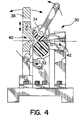
- membrane 10 may be suitably tensilized.
- a suitable tensilizing fixture 30 may be utilized for such purpose.
- fixture 30 preferably comprises two rollers 32, 34.
- a frame 36 secures rollers 32, 34.
- Each of the rollers 32, 34 are interference-fit under a load on the order of 50 pounds.
- Manual operation of a handle 38 engages and rotates the rollers 32,34, thereby drawing and working membrane 10 through the juncture.
- a concurrent force is applied to a trailing edge elongating the membrane 10. That force may be applied manually or by using mechanical meterized assistance (not shown).
- an inlet 40 and an outlet 42 are defined by fixture 30.
- membrane 10 advances while simultaneously being clamped and pulled backward at a force and rate so as to stretch and tensilize the film.
- tensilization of the membrane material results in elongation from 25 to 300%, more preferably from 50 to 200% and optimally from 125 to 150% of the membrane material or article/device formed thereof.
- the membrane materials useful in the context of the present invention can be tensilized using other known methods, such as by hand, manually or by automatic mechanisms. It should be appreciated that tensilization of the membrane materials useful in accordance with the present invention may be accomplished in any of a variety of ways, such as through the use of any conventional or hereafter devised method. It is believed that such tensilizing operations longitudinally strengthen the membrane film and lower the frictional coefficient by cold-flow molecular orientation of the membrane film. Annealing methods at 300-500 °F may also relieve some or most fabrication stresses.
- the membrane materials preferably exhibit a thickness (i.e. the thickness between surfaces 12 and 14) of less than 0,254 mm (0.010 inch), more preferably less than 0,1016 mm (0.004 inch), still more preferably less than 0,0635 mm (0.0025 inch) and even more preferably less than 0,0254 mm (0.001 inch).
- a membrane may evidence a film thickness of 0,0254 to 0,0508 mm (0.001 to 0.002 inches). At such dimensions the membrane is generally soft and supple. It should be appreciated however, that depending upon the particular application for which membrane 10 is configured, as will be described in greater detail herein below, the particular dimensions of membrane 10, specifically the particular thickness of membrane 10 may be modified as desired.
- Membrane 10 may be applied to and/or on the epidermal skin layer of a patient.
- a membrane 10 may be suitably applied to and/or on the skin layer of a patient (not shown) and suitably secured to the skin layer through the use of respective strips of adhesive material 44A-D applied to respective edges 16, 20, 22 and 24.
- Other modes of adhering membrane 10 to and/or on the skin of a patient may also suitably be utilized.
- membrane 10 may be configured in the shape of a conventional bandage or wound dressing material with adhesive material applied over the top of and/or extending around the membrane in a manner suitable to adhere the membrane to the patient.
- membrane 10 suitably serves as a bandage or wound covering, and in such configuration may be suitably used in a vented or alternatively used in an unvented fashion.
- the membrane preferably is extremely lightweight and semitransparent. Thus, damaged tissue is visible without the membrane being removed by health care personnel.
- Membrane 10 in such a configuration offers additional advantages over presently known materials in that the material exhibits high slip release, thereby minimizing disturbance of the healing tissues and/or wound, permitting enhanced recovery and reducing the risk of infection.
- tissue/membrane 10 interface may be vented.
- the temperature and oxygen content of the tissue/membrane interface can be controlled by passing a purified filtered air oxygen mixture through a tubing inlet 46 located between membrane 10 and the patient's skin, or alternatively through an aperture formed in membrane 10.
- the membrane/tissue interface is also vented through an opposing outlet tube 48.
- airborne bacteria is removed isolated from near the wound (e.g. damaged tissue) and the oxygen flow tends to accelerate healing thereby reducing infections.
- the oxygen feed may be combined with ultrasonic vaporizers and atomizers containing antibiotics and drugs that help penetrate the wound, thus also tending to increase the rate of healing.
- multiple membranes 10 may be suitably joined to form a sleeve-like configuration, such as sleeve 50 shown.
- Sleeve 50 may be formed by suitably adhering respective edges, such as edges 22 and 24 of facing membrane materials 10 to each other by sealing (e.g. heat-sealing) and/or use of suitable adhesives.
- sealing e.g. heat-sealing
- suitable adhesives e.g. heat-sealing
- the edges of the sleeve 50 may be suitably adhered to the extremity such as through the use of adhesive strips 52A, 52B.
- tissue region covered by sleeve 50 may be vented.
- an inlet tube 56 and an outlet tube 58 configured similarly to inlet 46 and outlet 48 described in conjunction with Fig. 2, are suitably positioned to facilitate temperature and/or oxygen content at the affected and covered region.
- Sleeve 50 may also be used in an unvented fashion (not shown).
- sleeve 50 may also be suitably inverted to reverse the heatsealed seams prior to securing sleeve 50 about and/or onto an extremity of a patient.
- suitable antibiotics or other dressing materials may be used in conjunction with the material.
- the membrane material may be used within a patient's body.
- a suitably configured membrane may be suitably implanted for the purpose of isolating body tissues, organs, or bone from the surrounding environment or for use as a tissue replacement article.
- Such isolation may be useful after a surgical procedure to promote healing and prevent fusing of natural tissue.
- the membrane may promote rebuilding and recovery due, in part, to its nonporous property.
- the membrane materials useful in the context of the present invention exhibit a porosity of less than 5 per 6,4516 cm 2 (5/sq. in.) at 0,0254 mm (0.001 inches) or less. Porosity of course, may depend upon the thickness and level of tensilizing.
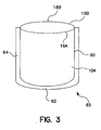
- a pair of membrane sheets 10A and 10B are suitably joined together such that three of the respective four edges of each of the sheets are adhered or sealed together.
- a pouch (bag) may be formed.
- a pouch 65 may be formed by joining together two membrane layers, one on top of the other, such that several edges are suitably sealed.
- a membrane 10A is suitably arranged over a membrane 10B, such as shown in Fig. 3, and the respective edges 14, 20, 24 thereof (as shown in Fig. 1) of each layer are heat sealed together.
- Fig. 1 the respective edges 14, 20, 24 thereof (as shown in Fig. 1) of each layer are heat sealed together.
- respective edges 16A (of membrane 10A) and 16B (of membrane 10B) are suitably not sealed to form an opening between membranes ioA and 10B.
- the edges which are sealed suitably form respective sealed edges 60, 62, and 64.
- any excess material is trimmed by conventional methods thus producing pouch 65.
- the pouch 65 can be inverted to put the sealed edges 60, 62 and 64 suitably inside of pouch 65 thereby formed.
- the sealed edges for example edges 60, 62 and 64 of pouch 65, can be formed in any conventional manner, for example through use of heat-sealing bars, sonic welding, use of a heat gun, a sintering oven, a thermal impulse, a hot iron, a hot bar or rollers, and or any other now known or hereafter devised combination of heat and pressure.
- the respective edges of membranes 10A and 10B that are to be sealed are brought to a gel temperature of 315 to 426 °C (600-800 °F) at a sufficient pressure for sufficient dwell time.
- the dwell time and pressure are dependent upon the film thickness as well as whether a tack weld or fusion weld is desired.
- the sealed edges or seals useful in the context of the present invention can vary, but typically are on the order of 0,396875 to 12,7 mm (1/64 to 1/2 of an inch) for most applications.
- Pouch 65 may be suitably used for surgical and/or laboratory isolation of tissues, body components or other articles.
- pouch 65 may be suitably configured to cradle, wrap, cover or isolate a medical implant device, such as a stent, or in other applications to contain bleeding in traumatic surgery situations.
- pouch 65 may be provided with one or more tabs for attaching the pouch to other structures and/or for closing the normally open end of pouch 65.
- multiple membranes 10 may be suitably joined to form a tubular body.
- Such tubular bodies may have broad applications for medicine to industry. Moreover, such tubular bodies may be useful for a peristaltic pumps.
- a tube 70 preferably comprises a generally cylindrical conduit having a first end 72, a second end 74 and an single sealed edge 76 extending along a longitudinal side thereof.
- the walls of tube 70 preferably have a thickness less than 0,254 mm (0.010 in.), and more preferably less than 0,635 mm (0.0025 in.), and still more preferably less than 0,0254 mm (0.001 inch).
- a membrane layer e.g. membrane 10
- the edges are placed on top of each other, and the longitudinal edges thereof heat sealed to form edge 76.
- a tube 80 preferably comprises two membrane layers 77, 78 which are heat sealed along two of their respective edges, for example in a conventional manner, to form tube 80 having a first end 82, a second end 84 and respective sealed edges 86, 88. Once edges 86, 88 of tube 80 are suitably formed, excess material may be trimmed, and a tube cut to a desired length.
- Tubes 70 and 80 may be suitably tensilized to improve the strength, slipperiness and flexibility thereof.
- tensilizing of polymeric films can be accomplished in a variety of ways. Tensilizing can be accomplished before and/or after forming tubes 70 and 80 through any conventional or hereafter devised method. In some cases tensilizing after tube formation will be desired, and a tensilizing fixture, such as that shown in Fig. 4, may be employed.
- the tube so formed in accordance with the present invention is preferably elongated from 25 to 300 percent, more preferably from 50 to 200 percent, and optimally from 125 to 150 percent.
- leading edge 82 of tube 80 is preferably not tensilized, whereas the remainder of tube 80, including trailing edge 84, is tensilized.
- leading edge 82 tends to exhibit a greater axial strength, and thus, can be more easily sized and ultimately attached to mating tubes, fittings and/or other devices.
- leading edge 82 is fed through rollers 32, 34 and no drag pressure is exerted on leading edge 82 so that it remains non-tensilized.
- tubular bodies formed in accordance with the present invention may also be further treated to obtain other beneficial properties.
- the tubular bodies disclosed herein, such as tubes 70 and/or 80 may be suitably heat annealed to enhance axial burst pressure resistance.
- most axial burst pressure, for most tubes is restored from the linear molecular orientation stresses by heat annealing the formed tubing at 149 °C (300 °F) to 260°C (500 °F) for a period of time (ranging from a few seconds to a few minutes), while leaving in tact most of the reduced friction performance characteristics obtained through tensilization.
- the tubes so formed can be provided with a small cut or other slit in the desired direction and location of the desired tear.
- longitudinal tearing will initiate at such point and continue to a prescribed distance thereby allowing a tear or rip to be formed in the side of the tube.
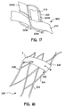
- a tube which is partially tensilized and partially not tensilized, such as shown in Fig. 7, may be used and connected to respective pieces of other tubing materials.
- a first tube 90 can be suitably configured to receive trailing edge 84.
- Tube 90 may be formed of any suitable material (e.g. polyvinyl chloride) and a second tube 92 exhibiting a larger internal diameter than tube 90 can be received in leading edge 82 of tube 80.
- tubes 90 and 92 can thereafter be manipulated such that tube 90 is worked interiorly of tube 92 so that a multi-layer multi-tube device is obtained.
- Such device may be used as a probe, introducer, catheter, balloon or other device.
- Such balloon device is described in more detail in U.S. Patent Application Serial No. 08/676,581.
- trailing edge 84 can suitably be threaded through the interior lumen of tube 90 by the use of a threading device 100.
- threading device 100 suitably comprises a rod 102 and a hook 104, hook 104 being suitably configured to receive an edge, for example trailing edge 84, of tube 80.
- a tube such as tube 70 and/or tube 80 may be suitably pulled through a wire loop pulling device 100 which is inserted through the interior lumen of an auxiliary tube, such as tube 90 and/or tube 92.
- auxiliary tube such as tube 90 and/or tube 92.
- device 100 pulls tube 70 and/or tube 80 into the inner lumen of tube 90 and/or tube 92.
- device 100 can be used to suitably invert the membrane-formed tube within the lumen of the carrying tube.
- multi-layer and/or multi-lumen tubes may be formed in accordance with various aspects of the present invention.
- three pieces of membrane material may be joined together to form a multi-lumen tube.
- a first sheet of membrane material 112 is placed on top of a second piece of membrane material 114, which second piece 114 is in turn placed on top of a third piece of membrane material 116.
- the longitudinal edges of the composite structure, namely respective edges 118 and 120 are suitably heat-sealed, for example in a conventional fashion or in any other way as described above.
- multi-lumen tube 110 may be used in the form shown in Fig. 11, or alternatively, may be inverted, such as through use of pulling device 100 (see Figs. 10 and 10A).
- the various layers 112, 114 and 116 each are formed of tensilized membrane material having a thickness on the order of 0,0508 mm (0.002 inch), and more preferably on the order of 0,0254 mm (0.001 inch).
- a tube 130 may be formed of four layers of membrane material, namely respective layers 132, 134, 136 and 138.
- layers 132, 134, 136 and 138 are suitably sealed at, for example, respective edges 140 and 142 to form longitudinal seals about the length thereof.
- Such seals are suitably formed by, for example, heat-sealing as described hereinabove.
- tube 130 provides a lumen between adjacent layers of material, namely a lumen 144 between juxtaposed layers 132 and 134, a lumen 146 between juxtaposed layers 134 and 136, and a lumen 148 between juxtaposed layers ig6 and 138.
- lumen 146 can suitably serve as a push rod sheath or introducer aperture.
- tube 130 may be modified such that lumen 146 initiates at a portion spatially located away from the leading edge of the tube.
- tube 130 can be suitably configured to have a leading edge comprising separate single lumen tubes, namely tubes 130A and 130B, which suitably communicate with tube 130, as shown.
- lumen 144 initiates in tube 130A which is suitably comprised of the leading edges of layers 132 and 134.
- lumen 148 is suitably formed by coupling of the leading edges of layers 136 and 138. As shown, layers 134 and 136 are not sealed together in proximity of the leading edge.
- tube 130A is provided with respective separately sealed edges 140A and 142A
- tube 130B is provided with respective separately sealed edges 140B and 142B.
- Respective edges 140A and 140B suitably communicate and terminate at edge 140
- respective edges 142A and 142B suitably communicate and terminate at edge 142.
- An instrument such as a push rod and/or the like, may suitably be passed into lumen 146 between the juncture of tubes 130A and 130B.
- a tube such as tube 80 as shown in Fig. 6, may be suitably inverted, that is, turned inside out, to form an inverted tube 150.
- tube 150 suitably has a first layer 152 joined at its longitudinal edges 154 and 156 to layer 158.
- inverted tube 150 may be separately used for various applications.
- tube 150 may be manipulated to form a variety of different constructs.
- a multi-lumen tube 150A may be formed simply by placing a seal 160 about the longitudinal axis of tube 150A.
- Seal 160 may be formed in any conventional manner, for example by heat sealing, and be variously configured to have any desired dimension. In such a configuration, respective apertures 162 and 164 are thereby formed in tube 150A.
- a multi-lumen tube of the type shown in Fig. 14 may be desirable over and/or used in place of the multi-lumen tube 110 shown in Fig. 11.
- aperture 162 is suitably formed by a portion 152A of layer 152 and a portion 158A of layer 158, with seals 160 and 154 forming the edges thereof.
- aperture 164 is suitably formed by another portion 152B of layer 152 and another portion 158B of layer 158 with seals 160 and 156 forming the edges thereof.
- apertures 162 and 164 preferably have similar dimensions, it should be appreciated that by locating seal 160 off of the longitudinal axis of tube 150, the dimensions of apertures 162 and 164 can be suitably altered. Stated another way, by moving seal 160 adjacent to edge 154, aperture 162 will decrease in size and aperture 164 will increase in size or vice versa.
- tube 150A can result in a further tube construct 150B.
- apertures 162 and 164 can be suitably pressed together such that the outward edges and respective apertures 166 and 168 are thereby formed; preferably apertures 166, 168 are separated at the innermost portion by seal 160.
- apertures 166 and 168 may be suitably maintained in that position by forming respective seals 170 and 172 (see Fig. 16) to enable formation of a further tube construct 150C.
- tube construct 150C suitably comprises a quad-lumen tube formed of apertures 162, 164, 166 and 168.
- Figs. 14-16 have been illustrated with reference to tube 150, similar to tube 80 shown in Fig. 6, it should be appreciated that various other constructs disclosed herein may also be similarly manipulated.
- the multilayer structures namely tubes 110 and 130 shown in Figs. 11 and 12, may be similarly manipulated.
- multiple inverted tubes, such as tube 150 may be suitably combined to form various other multi-lumen constructs.
- the membrane materials disclosed herein may be suitably used as coverings and/or coatings for various other devices.
- stents are used to separate tissues, organs or other members for a variety of medical purposes.
- Such stents may be formed of plastic, metal or other materials and may exhibit a multitude of configurations.
- the membrane materials disclosed herein are useful in covering such stents to render them more useful and offer significant advantages over currently available stents.
- a stent structure 200 suitably comprising a frame member 202, typically formed of wire or other material, is configured to exhibit a number of openings.
- frame 202 shown therein is suitably configured to exhibit respective openings 204A, 204B, 204C and 204D.
- various pieces of membrane material are simply weaved through the various apertures of frame 202.
- a first piece of membrane material 210 may be suitably weaved through apertures 204A and 204C.
- a second piece of material 212 may be suitably weaved through apertures 204A and 204B.
- various other suitably sized and dimensioned pieces of membrane material may be weaved through the other apertures formed within stent frame 202 and various other weave paths or patterns can be used.
- the various pieces of membrane material namely pieces 210 and 212 may be suitably secured to the stent at the end thereof (not shown) by a spot weld or other adhesive.
- an end of, for example, piece 210 may be wrapped around the end of the stent and heat-sealed upon itself to suitably secure that end of the membrane material to the end of the stent.
- a tab configuration (not shown) can be formed in the piece of material, the tab being suitably configured to enable attachment of the piece of material to stent frame 202.
- various weaving patterns may be obtained through uses of various sized materials. For example, in certain applications, it may be desirable to weave more than one piece of material through particular apertures and/or particular series of apertures, as will be apparent to those skilled in the art from the disclosure just provided.
- a suitable stent structure 220 is formed by a frame 222 optimally configured to exhibit a plurality of openings.
- Frame 222 includes at least a first end frame member 224 and a second end frame member 226.
- a suitably sized and dimensioned piece of membrane material 230 having a first end 232 and a second end 234 is suitably wrapped around stent frame 222.
- first end 232 is suitably wrapped around member 224; similarly, second end 234 is suitably wrapped around member 226.
- the respective ends of sheet 230 are suitably sealed to secure sheet 230 to stent frame 222.
- spot welding techniques such as through the application of heat at a particular spot along sheet 230 suitably are used.
- end 234 is tucked under frame member 226 and a suitable spot weld may be applied at point A.
- end 232 is wrapped around member 224 and may be preferably folded back over itself and then spot-welded, for example, at location B to securely hold end 232 to stent frame 222.
- a stent covering material 250 is suitably adhered to a stent frame 252 (shown only in part in Fig. 19), by a series of tabs 254 which are welded to portions of frame 252.
- a tab 254 is suitably welded to a portion of frame 252 so as to create a weld spot.
- Tab 254 suitably comprises a strip of a modified PTFE resin in accordance with the previously described materials.
- the strip is folded over a portion of stent 252 and then spot-welded to itself to form tab 254.
- material 250 is suitably applied to stent frame 252.
- material 250 is adhered to frame 252 by spot-welding material 250 to the various tabs 254 contained on frame 252.
- covering stent frame 252 in this manner enables covering material 250 to be secured to and positioned with respect to frame 252, while at the same time allowing a certain degree of movement or float.
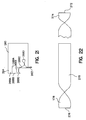
- a covering material 260 is suitably wrapped around a stent frame 262.
- the covering material can be wound in any particular pattern, for example in a straight pattern, such as is shown in Fig. 20, or in a helical or any other pattern.
- covering material 260 is suitably wrapped about a portion of frame 262 to secure covering material 260 to frame 262.
- Any mode of attachment herein described or hereafter devised by those skilled in the art can be utilized.
- tabs such as those shown in Fig. 19 may be utilized to secure covering material 260 to frame 262.
- a loaded position of stent frame 262 such as shown in Fig. 20A, can be obtained.
- covering material 260 can be suitably tensioned to draw frame 262 upon itself into a loaded position, thereafter, upon release of the tension, stent frame 262 can be caused to expand such as is shown in Fig. 20B, and ultimately to a final position such as is shown in Fig. 20C.
- covering material 260 is suitably cut at one end thereof to form a plurality of tabs.
- a leading edge 264 of covering 260 is suitably provided with a plurality of slits 266A, 266B, 266C to form a plurality of tabs 268A, 268B, 268C and 268D in leading edge 264.
- the tabs may be twisted such as shown with respect to tab 268C to form a weld receiving position.
- tab 268D once the weld receiving position is formed, it may be suitably folded back onto the remaining portion of covering 260 over a portion of frame 262 and then spot welded to secure tab 268D securely to material 260, thereby securing material 260 to frame 262.
- stent covering materials comprise the modified polytetrafluoroethylene resins described herein, it should be appreciated that in certain applications other materials may be suitably used.
- thicker materials such as PTFE, urethane, foils (metal and otherwise) and multi-layer structures may suitably be employed as covering materials.
- an alternative embodiment of the stent covering shown in Fig. 20 can be obtained by use of multiple coverings using a variation of the attachment mechanism shown in Fig. 21.
- one or more membrane materials 270 may be suitably formed such that at a leading edge 272 a tab 274 is formed.
- tab 274 is formed by twisting leading edge 272 over an angle of 180° or more.
- a tab 278 can be suitably formed in a like fashion.
- Material 270 can then be applied to a stent frame (not shown but similar to stent 262 shown in Fig. 20) such as by helically winding membrane 270 around the outer surface of the coiled frame.
- Material 270 may be secured to the frame by securing tab 274 at one end of the frame and securing tab 276 at another end of the frame.
- a further piece of material 270A may be suitably helically wrapped in a direction opposite the wrapping of material 270 and suitably secured to the frame by attachment of tabs 274A and 276A to the frame.
- tabs 274 and 278 may be suitably formed in other ways.
- material 270 could be cut (die-cut or otherwise) or suitably formed to exhibit such tabbed configurations.
- a single piece of membrane material 300 is suitably weaved through a portion of a stent frame 302 to form respective weld locations 304 and 306.
- Such weld locations can be used, as shown best in Fig. 23A, to attach a covering material 310 to frame 302 by spot welding material 310 to weld locations 304 and 306 of material 300.
- the resin material useful in accordance with the present invention in forming the various membranes and other constructs described herein may also be bonded to other surfaces.
- the various resins described herein can be bonded not only to themselves, such as to form the various seals disclosed herein, but also to other suitable surfaces formed from metals, plastics, thermoplastics, rubbers, etc.
- iron or copper pipe/tubing may be suitably enhanced for medical or industrial uses through use of an internal and/or external coating/covering of the membrane materials useful in the context of the present invention.
- the membrane materials can be bonded to coated or uncoated surfaces of the pipe/tubing.
- the pipe/tubing surfaces are coated with the same or similar resin material or other resin materials such as PFA, FEP, etc.
- Other devices/articles such as cylindrical polypropylene webs, woven polyester sleeves or porous PTFE grafts also can be coated with the resin materials disclosed herein.
- such bonding can be accomplished through the application of heat, which may be generated in any conventional manner, and/or sintering the film directly onto the pipe/tubing substrate.
- heat generating sources include a sintering oven, a heat gun, radiant KL-rods, heat bars, rollers, RF seals sonic welding devices and/or various lasers, for example, CO 2 or Yag and/or the like.
- a coated structure in accordance with this aspect of the present invention is illustrated with reference to Fig. 24, wherein a metallic (e.g. copper, iron, etc.) rod 400 is suitably provided with a polymeric coating 402, and applied to coating 402 is a layer of membrane material 404.
- the juncture between layers 404 and 402 may be suitably joined by tack welds 406 or be continuously sealed about the entire length thereof.
- tack welds may be suitably formed through use of laser or sonic welding thereby, partially securing layer 404 to layer 402.
- a layer of material in accordance with the present invention is preferably applied to the interior portion of a metal pipe 410.
- pipe 410 is first provided with a PFA, FEP, and/or the like emulsion coating, such as may be obtained by dipping pipe 410 into a desired FEP or PFA emulsion.
- a PFA, FEP, and/or the like emulsion coating such as may be obtained by dipping pipe 410 into a desired FEP or PFA emulsion.
- pipe 410 can be suitably provided with such FEP coating 412 through any conventional dipping process.
- a lining of the PTFE resin material may be provided to pipe 410 without use of the same.
- a membrane material layer 414 is suitably secured about its entire length to layer 412. While the examples shown in Fig. 24 and 25 utilize a covering material applied to a metallic base material, it should be appreciated that various other devices or materials may be similarly coated with the materials described herein.
Abstract
Claims (10)
- Tube pour applications médicales, comprenant une membrane formée d'une résine polytétrafluoroéthylène modifiée, ayant une première extrémité, une deuxième extrémité et un corps généralement tubulaire, scellé, réalisant un enjambement entre les deux, dans lequel ladite membrane comprend un homopolymère de polytétrafluoroéthylène qui est modifié avec moins de 5% de perfluoro-propyl-vinyl-éther.
- Tube selon la revendication 1, dans lequel ladite membrane a une épaisseur inférieure à 0,254 mm.
- Tube selon la revendication 1, comprenant
une première couche (112; 132) d'un matériau formé d'une résine polytétrafluoroéthylène modifiée comprenant moins de 5% de perfluoro-propyl-vinyl-éther,
une deuxième couche (114; 134) d'un matériau formé d'une résine polytétrafluoroéthylène modifiée comprenant moins de 5% de perfluoro-propyl-vinyl-éther, et
une troisième couche (116; 136) d'un matériau formé d'une résine polytétrafluoroéthylène modifiée comprenant moins de 5% de perfluoro-propyl-vinyl-éther ;
dans lequel chacune desdites couches comprend des premiers et deuxièmes bords longitudinaux (118, 120; 140, 142), chacun desdits premiers et desdits deuxièmes bords longitudinaux desdites couches étant scellé à chaud autour d'une portion de la longueur desdits bords longitudinaux. - Tube selon la revendication 3, dans lequel lesdits bords longitudinaux (118, 120; 140, 142) sont scellés autour de essentiellement toute leur longueur.
- Tube selon la revendication 3, comprenant également une quatrième couche (138) d'une résine polytétrafluoroéthylène modifiée comprenant moins de 5% de perfluoro-propyl-vinyl-éther, ladite quatrième couche (138) comprenant des premiers et deuxièmes bords longitudinaux (140, 142) qui sont scellés à chaud de façon appropriée sur lesdits premiers et deuxièmes bords longitudinaux d'au moins ladite troisième couche (136).
- Tube selon la revendication 3, dans lequel une épaisseur de chacune desdites couches est inférieure à 0,1016 mm.
- Tube selon la revendication 3, dans lequel une épaisseur de chacune desdites couches est comprise entre 0,0254 et 0,0508 mm.
- Tube selon la revendication 3, dans lequel ledit matériau est soumis à la traction.
- Tube selon la revendication 1, comprenant
un tube métallique (400, 410) ayant une première extrémité, une deuxième extrémité et un corps essentiellement continu réalisant un enjambement entre les deux,
un revêtement (404, 414) adhérant audit tube, ledit revêtement étant formé d'une résine polytétrafluoroéthylène modifiée, comprenant moins de 5% de perfluoro-propyl-vinyl-éther. - Tube revêtu selon la revendication 9, comprenant également une couche FEP (412) interposée entre ledit tube métallique (410) et ledit revêtement (414).
Applications Claiming Priority (5)
| Application Number | Priority Date | Filing Date | Title |
|---|---|---|---|
| US2340596P | 1996-08-14 | 1996-08-14 | |
| US23405P | 1996-08-14 | ||
| US3058996P | 1996-11-14 | 1996-11-14 | |
| US30589P | 1996-11-14 | ||
| PCT/US1997/014377 WO1998007450A2 (fr) | 1996-08-14 | 1997-08-14 | Membranes adaptees a l'usage medical |
Publications (3)
| Publication Number | Publication Date |
|---|---|
| EP0932374A2 EP0932374A2 (fr) | 1999-08-04 |
| EP0932374A4 EP0932374A4 (fr) | 2004-08-11 |
| EP0932374B1 true EP0932374B1 (fr) | 2007-04-11 |
Family
ID=26697097
Family Applications (1)
| Application Number | Title | Priority Date | Filing Date |
|---|---|---|---|
| EP97938329A Expired - Lifetime EP0932374B1 (fr) | 1996-08-14 | 1997-08-14 | Membranes adaptees a l'usage medical |
Country Status (5)
| Country | Link |
|---|---|
| US (1) | US6240968B1 (fr) |
| EP (1) | EP0932374B1 (fr) |
| AU (1) | AU4068797A (fr) |
| DE (1) | DE69737600T2 (fr) |
| WO (1) | WO1998007450A2 (fr) |
Families Citing this family (40)
| Publication number | Priority date | Publication date | Assignee | Title |
|---|---|---|---|---|
| US6262371B1 (en) * | 1999-06-23 | 2001-07-17 | Marc Talon, Inc. | Method and apparatus for dividing a conduit into compartments |
| EP1207819B1 (fr) * | 1999-08-06 | 2009-03-04 | Cook Biotech, Inc. | Structures tubulaires pour greffes |
| US6304698B1 (en) | 1999-09-22 | 2001-10-16 | Milliken & Company | Conduit insert for optical fiber cable |
| US8574146B2 (en) * | 2000-04-14 | 2013-11-05 | Attenuex Technologies, Inc. | Implant with high vapor pressure medium |
| US6682473B1 (en) | 2000-04-14 | 2004-01-27 | Solace Therapeutics, Inc. | Devices and methods for attenuation of pressure waves in the body |
| US10327880B2 (en) | 2000-04-14 | 2019-06-25 | Attenuex Technologies, Inc. | Attenuation device for use in an anatomical structure |
| US6571833B1 (en) * | 2000-07-14 | 2003-06-03 | Milliken & Company | Optic cable conduit insert and method of manufacture |
| US6718100B2 (en) * | 2002-03-28 | 2004-04-06 | Milliken & Company | Fire resistant conduit insert for optical fiber cable |
| US6886601B2 (en) | 2002-03-29 | 2005-05-03 | Tvc Communications, L.L.C. | Multi-compartment aerial duct |
| RU2319056C2 (ru) * | 2002-08-28 | 2008-03-10 | ТиВиСи Коммьюникейшнз | Конструкция удлиненного рукава для кабельного канала |
| US20040097957A1 (en) * | 2002-10-18 | 2004-05-20 | Marc Jaker | Medical device, drug delivery and lab sampling system utilizing an inverting sheath technology |
| US7655021B2 (en) * | 2003-03-10 | 2010-02-02 | Boston Scientific Scimed, Inc. | Dilator with expandable member |
| US20050048292A1 (en) * | 2003-05-16 | 2005-03-03 | Hammar Jarod R. | Composite plastic material |
| US20050245876A1 (en) * | 2003-12-24 | 2005-11-03 | Accessclosure, Inc. | Apparatus and methods for facilitating access through a puncture including sealing compound therein |
| US20050177025A1 (en) * | 2004-01-28 | 2005-08-11 | Marc Jaker | Prophylactic polymer probe cover |
| US7425202B2 (en) * | 2004-03-05 | 2008-09-16 | Percutaneous Systems, Inc. | Non-seeding biopsy device and method |
| US7972292B2 (en) | 2005-07-06 | 2011-07-05 | Percutaneous Systems, Inc. | Methods and apparatus for deploying ureteral stents |
| US7883516B2 (en) * | 2004-07-07 | 2011-02-08 | Percutaneous Systems, Inc. | Methods for removing kidney stones from the ureter |
| US7462183B2 (en) | 2004-07-07 | 2008-12-09 | Percutaneous Systems, Inc. | Methods for deploying conformed structures in body lumens |
| US7255687B2 (en) * | 2004-11-19 | 2007-08-14 | Percutaneous Systems, Inc. | Systems and methods for luminal access |
| US20060173525A1 (en) * | 2005-02-02 | 2006-08-03 | Percutaneous Systems, Inc. | Methods and systems for deploying luminal prostheses |
| US20070073107A1 (en) * | 2005-09-23 | 2007-03-29 | Percutaneous Systems, Inc. | Methods and systems for sheathing tubular medical instruments |
| EP1940316B1 (fr) | 2005-09-26 | 2015-10-21 | AttenueX Technologies, Inc. | Dispositif d'attenuation de pression |
| US20070106233A1 (en) * | 2005-10-20 | 2007-05-10 | Percutaneous Systems, Inc. | Systems and methods for dilating and accessing body lumens |
| US20080033396A1 (en) * | 2006-08-01 | 2008-02-07 | Percutaneous Systems, Inc. | Vascular sheaths and methods for their deployment |
| US7879066B2 (en) * | 2007-07-13 | 2011-02-01 | Percutaneous Sustems, Inc. | Apparatus for occluding body lumens |
| US8475489B2 (en) | 2007-07-13 | 2013-07-02 | Percutaneous Systems, Inc. | Apparatus for occluding body lumens |
| US9650479B2 (en) | 2007-10-04 | 2017-05-16 | W. L. Gore & Associates, Inc. | Dense articles formed from tetrafluoroethylene core shell copolymers and methods of making the same |
| US9040646B2 (en) * | 2007-10-04 | 2015-05-26 | W. L. Gore & Associates, Inc. | Expandable TFE copolymers, methods of making, and porous, expanded articles thereof |
| US8986291B2 (en) * | 2008-12-01 | 2015-03-24 | Percutaneous Systems, Inc. | Methods and systems for capturing and removing urinary stones from body cavities |
| US9689512B2 (en) * | 2009-02-20 | 2017-06-27 | Hobart Brothers Company | Air hose delivery assembly with inner liner |
| US20110041854A1 (en) * | 2009-08-18 | 2011-02-24 | Julia Suzanne Rasor | Everting device and method for tracheostomy |
| US9468547B2 (en) | 2010-11-11 | 2016-10-18 | W. L. Gore & Associates, Inc. | Deployment of endoluminal devices |
| US9414944B2 (en) | 2010-11-11 | 2016-08-16 | W. L. Gore & Associates, Inc. | Deployment sleeve shortening mechanism |
| US20120125471A1 (en) * | 2010-11-18 | 2012-05-24 | Chun-Ping Kuo | Water Pipe Structure |
| GB2502762B (en) | 2011-03-10 | 2018-12-26 | Adc Tech Int Ltd | Air purifier having an electret module |
| WO2012138753A1 (fr) * | 2011-04-04 | 2012-10-11 | Sessions Pharmaceuticals Inc. | Pansement pour plaie |
| US8894563B2 (en) | 2012-08-10 | 2014-11-25 | Attenuex Technologies, Inc. | Methods and systems for performing a medical procedure |
| US9644054B2 (en) | 2014-12-19 | 2017-05-09 | W. L. Gore & Associates, Inc. | Dense articles formed from tetrafluoroethylene core shell copolymers and methods of making the same |
| CN113677256A (zh) | 2019-02-07 | 2021-11-19 | 索雷斯医疗公司 | 压力衰减装置 |
Family Cites Families (11)
| Publication number | Priority date | Publication date | Assignee | Title |
|---|---|---|---|---|
| US5194335A (en) * | 1984-04-13 | 1993-03-16 | Chemical Fabrics Corporation | Fluoropolymer coating and casting compositions and films derived therefrom |
| US4701291A (en) * | 1986-07-25 | 1987-10-20 | The Duriron Company, Inc. | Process of isostatic molding and bonding fluoropolymers |
| US5088483A (en) * | 1988-11-04 | 1992-02-18 | Minnesota Mining And Manufacturing Co. | Adhesive frame bandage |
| US5560986A (en) * | 1990-04-27 | 1996-10-01 | W. L. Gore & Associates, Inc. | Porous polytetrafluoroethylene sheet composition |
| US5531717A (en) * | 1993-12-12 | 1996-07-02 | Rtc, Inc. | Non-contaminating probe and methods of making and using same |
| US5197976A (en) | 1991-09-16 | 1993-03-30 | Atrium Medical Corporation | Manually separable multi-lumen vascular graft |
| US5399307A (en) * | 1993-06-18 | 1995-03-21 | Dalton; Robert E. | Methods of compression molding two or more polytetrafluoroethylene resin layers |
| US6159565A (en) * | 1993-08-18 | 2000-12-12 | W. L. Gore & Associates, Inc. | Thin-wall intraluminal graft |
| CA2183350C (fr) | 1994-09-02 | 1999-04-27 | Phillip A. Branca | Compositions de polytetrafluoroethylene poreuses |
| US5676688A (en) | 1995-02-06 | 1997-10-14 | Rtc, Inc. | Variably inflatable medical device |
| DE19882383T1 (de) * | 1997-05-12 | 2000-05-25 | Rtc Inc | Für medizinische Zwecke geeignete elektrisch leitfähige Membran |
-
1997
- 1997-08-14 DE DE69737600T patent/DE69737600T2/de not_active Expired - Lifetime
- 1997-08-14 US US08/911,469 patent/US6240968B1/en not_active Expired - Lifetime
- 1997-08-14 WO PCT/US1997/014377 patent/WO1998007450A2/fr active IP Right Grant
- 1997-08-14 AU AU40687/97A patent/AU4068797A/en not_active Abandoned
- 1997-08-14 EP EP97938329A patent/EP0932374B1/fr not_active Expired - Lifetime
Non-Patent Citations (1)
| Title |
|---|
| None * |
Also Published As
| Publication number | Publication date |
|---|---|
| WO1998007450A9 (fr) | 1998-10-15 |
| WO1998007450A2 (fr) | 1998-02-26 |
| EP0932374A4 (fr) | 2004-08-11 |
| DE69737600T2 (de) | 2007-12-13 |
| US6240968B1 (en) | 2001-06-05 |
| AU4068797A (en) | 1998-03-06 |
| DE69737600D1 (de) | 2007-05-24 |
| WO1998007450A3 (fr) | 1998-02-26 |
| EP0932374A2 (fr) | 1999-08-04 |
Similar Documents
| Publication | Publication Date | Title |
|---|---|---|
| EP0932374B1 (fr) | Membranes adaptees a l'usage medical | |
| CA2167708C (fr) | Tube de polytetrafluoroethylene, a paroi de faible epaisseur | |
| US5718973A (en) | Tubular intraluminal graft | |
| US7682553B2 (en) | Balloon structure with PTFE component | |
| US7279208B1 (en) | Thin-wall polytetrafluoroethylene tube | |
| EP0586717B1 (fr) | Tube endotrachéal et son procédé de fabrication | |
| CA2624287C (fr) | Catheters pourvus d'un revetement lubrifiant et procedes de fabrication et d'utilisation de ces catheters | |
| JP5624321B2 (ja) | 人体からの悪臭物質輸送用シリコーンベースチューブ | |
| US6159565A (en) | Thin-wall intraluminal graft | |
| US6428506B1 (en) | Medical device formed of ultrahigh molecular weight polyethylene | |
| CA2184868C (fr) | Tube multicouche exempt de pvc pour usage medical; procede de fabrication et utilisation | |
| US5628786A (en) | Radially expandable vascular graft with resistance to longitudinal compression and method of making same | |
| AU2435601A (en) | Medical device formed of ultrahigh molecular weight polyolefin | |
| CA2601134A1 (fr) | Dispositifs implantables avec reduction de fuite sur le site de piqure par l'aiguille | |
| EP3366320B1 (fr) | Matériaux poreux possédant une microstructure fibrillaire et un revêtement fracturable | |
| US20020061375A1 (en) | Insulated intravenous administration tubing | |
| CA2666161A1 (fr) | Greffons en eptfe a plusieurs bifurcations et protheses stent-greffon, et procede de fabrication | |
| GB2429407A (en) | Thin-walled vascular graft |
Legal Events
| Date | Code | Title | Description |
|---|---|---|---|
| PUAI | Public reference made under article 153(3) epc to a published international application that has entered the european phase |
Free format text: ORIGINAL CODE: 0009012 |
|
| 17P | Request for examination filed |
Effective date: 19990225 |
|
| AK | Designated contracting states |
Kind code of ref document: A2 Designated state(s): CH DE ES FR GB IE IT LI SE |
|
| A4 | Supplementary search report drawn up and despatched |
Effective date: 20040625 |
|
| RIC1 | Information provided on ipc code assigned before grant |
Ipc: 7A 61L 31/04 B Ipc: 7A 61F 2/04 A |
|
| RIC1 | Information provided on ipc code assigned before grant |
Ipc: 7A 61F 13/00 B Ipc: 7A 61F 2/04 A |
|
| 17Q | First examination report despatched |
Effective date: 20041126 |
|
| RAP1 | Party data changed (applicant data changed or rights of an application transferred) |
Owner name: JAKER, MARC L. Owner name: BIGONZI-JAKER, ANNA MARIE Owner name: MEMCATH TECHNOLOGIES LLC |
|
| RAP1 | Party data changed (applicant data changed or rights of an application transferred) |
Owner name: MEMCATH TECHNOLOGIES LLC |
|
| GRAP | Despatch of communication of intention to grant a patent |
Free format text: ORIGINAL CODE: EPIDOSNIGR1 |
|
| GRAS | Grant fee paid |
Free format text: ORIGINAL CODE: EPIDOSNIGR3 |
|
| GRAA | (expected) grant |
Free format text: ORIGINAL CODE: 0009210 |
|
| AK | Designated contracting states |
Kind code of ref document: B1 Designated state(s): CH DE ES FR GB IE IT LI SE |
|
| PG25 | Lapsed in a contracting state [announced via postgrant information from national office to epo] |
Ref country code: LI Free format text: LAPSE BECAUSE OF FAILURE TO SUBMIT A TRANSLATION OF THE DESCRIPTION OR TO PAY THE FEE WITHIN THE PRESCRIBED TIME-LIMIT Effective date: 20070411 Ref country code: CH Free format text: LAPSE BECAUSE OF FAILURE TO SUBMIT A TRANSLATION OF THE DESCRIPTION OR TO PAY THE FEE WITHIN THE PRESCRIBED TIME-LIMIT Effective date: 20070411 |
|
| REG | Reference to a national code |
Ref country code: GB Ref legal event code: FG4D |
|
| REG | Reference to a national code |
Ref country code: CH Ref legal event code: EP |
|
| REG | Reference to a national code |
Ref country code: IE Ref legal event code: FG4D |
|
| REF | Corresponds to: |
Ref document number: 69737600 Country of ref document: DE Date of ref document: 20070524 Kind code of ref document: P |
|
| PG25 | Lapsed in a contracting state [announced via postgrant information from national office to epo] |
Ref country code: SE Free format text: LAPSE BECAUSE OF FAILURE TO SUBMIT A TRANSLATION OF THE DESCRIPTION OR TO PAY THE FEE WITHIN THE PRESCRIBED TIME-LIMIT Effective date: 20070711 |
|
| PG25 | Lapsed in a contracting state [announced via postgrant information from national office to epo] |
Ref country code: ES Free format text: LAPSE BECAUSE OF FAILURE TO SUBMIT A TRANSLATION OF THE DESCRIPTION OR TO PAY THE FEE WITHIN THE PRESCRIBED TIME-LIMIT Effective date: 20070722 |
|
| ET | Fr: translation filed | ||
| REG | Reference to a national code |
Ref country code: CH Ref legal event code: PL |
|
| PLBE | No opposition filed within time limit |
Free format text: ORIGINAL CODE: 0009261 |
|
| STAA | Information on the status of an ep patent application or granted ep patent |
Free format text: STATUS: NO OPPOSITION FILED WITHIN TIME LIMIT |
|
| 26N | No opposition filed |
Effective date: 20080114 |
|
| PG25 | Lapsed in a contracting state [announced via postgrant information from national office to epo] |
Ref country code: IE Free format text: LAPSE BECAUSE OF NON-PAYMENT OF DUE FEES Effective date: 20070814 |
|
| PGFP | Annual fee paid to national office [announced via postgrant information from national office to epo] |
Ref country code: IT Payment date: 20120824 Year of fee payment: 16 |
|
| PG25 | Lapsed in a contracting state [announced via postgrant information from national office to epo] |
Ref country code: IT Free format text: LAPSE BECAUSE OF NON-PAYMENT OF DUE FEES Effective date: 20130814 |
|
| PGFP | Annual fee paid to national office [announced via postgrant information from national office to epo] |
Ref country code: DE Payment date: 20140827 Year of fee payment: 18 |
|
| PGFP | Annual fee paid to national office [announced via postgrant information from national office to epo] |
Ref country code: FR Payment date: 20140818 Year of fee payment: 18 Ref country code: GB Payment date: 20140827 Year of fee payment: 18 |
|
| REG | Reference to a national code |
Ref country code: DE Ref legal event code: R119 Ref document number: 69737600 Country of ref document: DE |
|
| GBPC | Gb: european patent ceased through non-payment of renewal fee |
Effective date: 20150814 |
|
| REG | Reference to a national code |
Ref country code: FR Ref legal event code: ST Effective date: 20160429 |
|
| PG25 | Lapsed in a contracting state [announced via postgrant information from national office to epo] |
Ref country code: GB Free format text: LAPSE BECAUSE OF NON-PAYMENT OF DUE FEES Effective date: 20150814 Ref country code: DE Free format text: LAPSE BECAUSE OF NON-PAYMENT OF DUE FEES Effective date: 20160301 |
|
| PG25 | Lapsed in a contracting state [announced via postgrant information from national office to epo] |
Ref country code: FR Free format text: LAPSE BECAUSE OF NON-PAYMENT OF DUE FEES Effective date: 20150831 |