EP2103793A2 - Durchflusssteuerung für Turbolader - Google Patents
Durchflusssteuerung für Turbolader Download PDFInfo
- Publication number
- EP2103793A2 EP2103793A2 EP09155507A EP09155507A EP2103793A2 EP 2103793 A2 EP2103793 A2 EP 2103793A2 EP 09155507 A EP09155507 A EP 09155507A EP 09155507 A EP09155507 A EP 09155507A EP 2103793 A2 EP2103793 A2 EP 2103793A2
- Authority
- EP
- European Patent Office
- Prior art keywords
- peripheral member
- guide portions
- inner peripheral
- gas passages
- outer peripheral
- Prior art date
- Legal status (The legal status is an assumption and is not a legal conclusion. Google has not performed a legal analysis and makes no representation as to the accuracy of the status listed.)
- Withdrawn
Links
Images


Classifications
-
- F—MECHANICAL ENGINEERING; LIGHTING; HEATING; WEAPONS; BLASTING
- F01—MACHINES OR ENGINES IN GENERAL; ENGINE PLANTS IN GENERAL; STEAM ENGINES
- F01D—NON-POSITIVE DISPLACEMENT MACHINES OR ENGINES, e.g. STEAM TURBINES
- F01D17/00—Regulating or controlling by varying flow
- F01D17/10—Final actuators
- F01D17/12—Final actuators arranged in stator parts
- F01D17/14—Final actuators arranged in stator parts varying effective cross-sectional area of nozzles or guide conduits
- F01D17/16—Final actuators arranged in stator parts varying effective cross-sectional area of nozzles or guide conduits by means of nozzle vanes
- F01D17/165—Final actuators arranged in stator parts varying effective cross-sectional area of nozzles or guide conduits by means of nozzle vanes for radial flow, i.e. the vanes turning around axes which are essentially parallel to the rotor centre line
-
- F—MECHANICAL ENGINEERING; LIGHTING; HEATING; WEAPONS; BLASTING
- F01—MACHINES OR ENGINES IN GENERAL; ENGINE PLANTS IN GENERAL; STEAM ENGINES
- F01D—NON-POSITIVE DISPLACEMENT MACHINES OR ENGINES, e.g. STEAM TURBINES
- F01D17/00—Regulating or controlling by varying flow
- F01D17/10—Final actuators
- F01D17/12—Final actuators arranged in stator parts
- F01D17/14—Final actuators arranged in stator parts varying effective cross-sectional area of nozzles or guide conduits
- F01D17/141—Final actuators arranged in stator parts varying effective cross-sectional area of nozzles or guide conduits by means of shiftable members or valves obturating part of the flow path
-
- F—MECHANICAL ENGINEERING; LIGHTING; HEATING; WEAPONS; BLASTING
- F05—INDEXING SCHEMES RELATING TO ENGINES OR PUMPS IN VARIOUS SUBCLASSES OF CLASSES F01-F04
- F05D—INDEXING SCHEME FOR ASPECTS RELATING TO NON-POSITIVE-DISPLACEMENT MACHINES OR ENGINES, GAS-TURBINES OR JET-PROPULSION PLANTS
- F05D2220/00—Application
- F05D2220/40—Application in turbochargers
-
- F—MECHANICAL ENGINEERING; LIGHTING; HEATING; WEAPONS; BLASTING
- F05—INDEXING SCHEMES RELATING TO ENGINES OR PUMPS IN VARIOUS SUBCLASSES OF CLASSES F01-F04
- F05D—INDEXING SCHEME FOR ASPECTS RELATING TO NON-POSITIVE-DISPLACEMENT MACHINES OR ENGINES, GAS-TURBINES OR JET-PROPULSION PLANTS
- F05D2250/00—Geometry
- F05D2250/30—Arrangement of components
- F05D2250/35—Arrangement of components rotated
Definitions
- the invention relates to a turbocharger, and more specifically, to a turbocharger that changes the flow rate of gas to a turbine wheel.
- JP-A-2000-199433 describes turbocharger in which a large-diameter disc portion is provided between two levers so as to abut against one of both the levers.
- the levers are turned synchronously with each other.
- the large-diameter disc portion comes into abutment on one of both the levers to thereby control the angle of a nozzle vane when fully open.
- the large-diameter disc portion comes into abutment on the other of both the levers to thereby control the angle of the nozzle vane when fully closed.
- JP-A-11-148364 describes a turning center of a turbine-side movable nozzle vane that is provided on an inner edge portion of a vane support body, and a turning center of a scroll-side movable nozzle vane that is provided on an outer edge portion of the vane support body.
- a nozzle vane that assumes a fully open position when a stopper hits one longitudinal end of a guide, and assumes a fully closed position when the stopper is in contact with the other longitudinal end of the guide is described in Japanese Patent Application Publication No. 10-37754 ( JP-A-10-37754 ).
- JP-A-5-18258 there is described an art in which one of flow passage walls on both sides, which sandwich a nozzle vane, is a movable wall turnable around a turbine wheel shaft, and the other is a fixed wall facing the movable wall.
- variable nozzle turbochargers there is a problem in that the flow of gas in a turbine wheel cannot be sufficiently reduced.
- the invention provides a turbocharger capable of sufficiently reducing the flow of gas to a turbine wheel.
- a turbocharger includes: a turbine wheel, an inner peripheral member that is provided outside the turbine wheel and that guides exhaust gas to the turbine wheel, an annular outer peripheral member that is provided adjacent to and outside of the inner peripheral member and that is rotatable relative to the inner peripheral member in a circumferential direction, a plurality of inner guide portions that is provided on the inner peripheral member and that define inner gas passages between successive inner guide portions, and a plurality of outer guide portions that is provided on the outer peripheral member and that define gas passages between successive outer guide portions.
- the flow of gas to the turbine wheel through the inner gas passages and the outer gas passages is adjusted by turning one of the outer peripheral member or the inner peripheral member with respect to the other of the outer peripheral member or the inner peripheral member so that the inner guide portions restrict the flow of the outer gas passages in accordance with the degree to which the outer peripheral member or the inner peripheral member is turned.
- the inner guide portions close the outer gas passages in accordance with the turning position of the outer peripheral member with respect to the inner peripheral member.
- the flow of gas to the turbine wheel through the gas passages may be restricted or shut off.
- FIG. 1 is a plan view of a turbocharger according to the first embodiment of the invention.
- a turbocharger 1 has a turbine wheel 30, and a turbine housing 40 in which the turbine wheel 30 is accommodated.
- An inner peripheral member 23 and an outer peripheral member 13 are accommodated in the turbine housing 40 and disposed outside the turbine wheel 30.
- Both the inner peripheral member 23 and the outer peripheral member 13 are ring shaped, and are slidably in contact with each other.
- the inner peripheral member 23 may be fixed in position, and the outer peripheral member 13 may be turnably provided.
- the outer peripheral member 13 may be fixed in position, and the inner peripheral member 23 may be a turnably provided.
- the inner peripheral member 23 and the outer peripheral member 13 are provided with inner guide portions 21 and outer guide portions 11 respectively, which define gas passages 22 and gas passages 12 provided between the respective inner guide portions 21 and outer guide portions 11.
- the sides of each inner guide portions 21 are curved.
- the inner guide portions 21 are disposed at regular intervals on the inner peripheral member 23 such that the outer peripheral edges 21a of the inner guide portions 21 extend along the outer peripheral edge of the inner peripheral member 23.
- the sides of each outer guide portions 11 are curved.
- the outer guide portions 11 are disposed at regular intervals on the outer peripheral member 13 such that the inner peripheral edges 11a extend along the inner peripheral edge of the outer peripheral member 13.
- the inner guide portion 21 and the outer guide portions 11 are designed to,slide with respect to each other as well.
- the gas passages 22 and 12 are concave, and exhaust gas supplied from a gas passage 41 of the turbine housing 40 flows toward the turbine wheel 30 in directions indicated by arrows 42 via the gas passages 12 and 22. Thus, the turbine wheel 30 is rotated.
- the turbine wheel 30 is connected to a turbine shaft, and the turbine shaft is, in turn, connected to a compressor.
- the compressor compresses mixture or intake air.
- FIG. 2 is a sectional view taken along a line II-II in FIG. 1 .
- the turbine wheel 30 is held rotatable around a centerline 31.
- the turbine housing 40 is provided on an outer periphery of the turbine wheel 30, and the turbine housing 40 is provided with the gas passage 41, which assumes a spiral shape.
- the inner guide portions 21 are mounted on the inner peripheral member 23, and the outer guide portions 11 are mounted on the outer peripheral member 13.
- each outer guide portion 11 and the corresponding inner guide portion 21 are in contact with each other.
- the invention is not limited to this construction.
- Each of the guide portions 11 and a corresponding one of the guide portions 21 may be slightly spaced apart from each other.
- FIG. 3 is a view showing the turbocharger in which the inner peripheral member is relative to the outer peripheral member where the flow of gas is shut off.
- the inner guide portions 21 block the outer gas passages 12.
- gas cannot be supplied from the out gas passages 12 to the inner gas passages 22.
- gas exhaust gas
- gas cannot be introduced from the outer periphery side to the inner periphery side, thereby significantly restricting the flow of gas toward the turbine wheel 30.
- FIG. 4 is a graph showing a relationship between a relative rotational angle between the inner peripheral member and the outer peripheral member and an area of a nozzle throat.
- the axis of ordinate “AREA OF NOZZLE THROAT” represents the flow rate of gas through the turbine wheel 30 via the outer gas passage 12 and the inner gas passage 22.
- the flow rate of gas through the gas passages may be changed in a continuous manner.
- the turbocharger 1 is equipped with the turbine wheel 30; the annular inner peripheral member 23 that is located outside the turbine wheel 30 and that guides gas to the turbine wheel 30; and the outer peripheral member 13 that is located to the outside of and adjacent to the inner peripheral member 23 and that turns with respect to the inner peripheral member 23 in a circumferential direction.
- the inner peripheral member 23 and the outer peripheral member 13 are provided respectively with the plurality of the outer guide portions 11 and inner guide portions 21 that guide gas inward from the outer periphery, and the outer gas passages 12 and inner gas passages 22 are provided between the plurality of the respective outer guide portions 11 and inner guide portions 21.
- the inner guide portions 21 close the outer gas passages 12 in accordance with the turning position of the outer peripheral member 13 with respect to the inner peripheral member 23, so that the flow of gas to the turbine wheel 30 through the gas passages may be restricted or shut off.
- the ring-like inner peripheral member 23 and the ring-like outer peripheral member 13 are rotated relative to each other, and the area of the nozzle throat may thereby be adjusted. Furthermore, the nozzle throat may be closed fully so that the flow of gas is shut off.
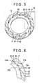
- FIG. 5 is a perspective view showing part of a turbocharger according to the second embodiment of the invention.
- FIG. 6 is a view showing a region surrounded by VI in FIG. 5 on an enlarged scale.
- the turbocharger 1 according to the second embodiment of the invention differs from the turbocharger 1 according to the first embodiment of the invention in that the radial thickness of the inner guide portions 21 is smaller than in the first embodiment of the invention.
- the thickness of the inner guide portions 21 By reducing the thickness of the inner guide portions 21, the distance between the outer edge portion of the inner peripheral member 23 and the turbine wheel may be reduced.
- the area of the throat in the traveling direction of gas may be changed smoothly.
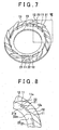
- FIG. 7 is a perspective view of the turbocharger when the nozzle throat is fully closed.
- FIG 8 is a view showing a region surrounded by VIII in FIG. 7 on an enlarged scale. Referring to FIGS. 7 and 8 , when the nozzle throat is fully closed, the inner guide portions 21 block off the respective outer gas passages 12. Thus, the flow of gas from the outer peripheral portion toward the inner peripheral portion can be shut off.
- FIG. 9 is a sectional view of a turbocharger according to the third embodiment of the invention.
- FIG. 10 is a plan view of the turbocharger according to the third embodiment of the invention. Referring to FIGS. 9 and 10 , in the turbocharger 1 according to the third embodiment of the invention, the turbine housing 40 is provided with a drill path 45 as a waste gate.
- the drill path 45 is a passage for discharging gas in the gas passage 41 provided in the turbine housing 40 without the intermediary of the turbine wheel 30. As shown in FIG. 10 , when the inner guide portions 21 are positioned to fully close all the outer gas passages 12, the drill path 45 is closed by the outer guide portions 11, so that no gas flows through the drill path 45.
- a single drill path 45 may be provided as shown in FIG. 10 .
- a plurality of drill paths 45 may be provided.
- the opening portion of the drill path 45 is shown formed above the outer guide portions 11, but may be formed above the inner guide portions 21 instead.
- the inner peripheral edge 11a of each outer guide portions 11 is the same with the inner peripheral edge 12a of each outer gas passages 12.
- the width of the inner peripheral edge 11a of each outer guide portions 11 may differ from that of each outer gas passages 12.
- the inner peripheral edge 12a of each outer gas passages 12 is the same with as the outer peripheral edge 21a of each inner guide portions 21.
- the width of the outer peripheral edge 21a of each inner guide portions 21 may be longer than that of the inner peripheral edge 12a of each gas passages 12.
- each outer guide portions 11 and the outer peripheral edge 21a of each inner guide portions 21 may be equal in width to each other or different in width from each other.
- the internal combustion engine may be a gasoline engine or a diesel engine.
- a rotary engine as well as a reciprocal engine may be employed.
- the invention is applicable to various forms of engines such as inline engines, V-type engines, horizontally-opposed engines, W-type engines, and the like.
- the mechanism for turning the turbine wheel 30 is not limited to mechanisms utilizing exhaust gas only.
- a motor may be used to assist the rotation of the turbine wheel 30.
- EGR exhaust gas recirculation
- a turbocharger 1 includes a turbine wheel 30, an inner peripheral member 23 provided outside the turbine wheel 30, and an outer peripheral member 13 provided outside the inner peripheral member 23 that can turn relative to the inner peripheral member 23 in the circumferential direction.
- the inner peripheral member 23 and the outer peripheral member 13 are provided with a plurality of inner guide portions 21 and a plurality of outer guide portions 11, respectively, that define gas passages 22 and 12 between successive guide portions 21, 11.
- the flow of gas to the turbine wheel 30 through the gas passages may be adjusted by turning one of the outer peripheral member 13 or the inner peripheral member 23 so that the inner guide portions 21 restrict the flow of gas through the gas passages 12 of the outer peripheral member 13.
Landscapes
- Engineering & Computer Science (AREA)
- Mechanical Engineering (AREA)
- General Engineering & Computer Science (AREA)
- Supercharger (AREA)
- Control Of Turbines (AREA)
Applications Claiming Priority (1)
| Application Number | Priority Date | Filing Date | Title |
|---|---|---|---|
| JP2008072062A JP2009228479A (ja) | 2008-03-19 | 2008-03-19 | ターボチャージャ |
Publications (2)
| Publication Number | Publication Date |
|---|---|
| EP2103793A2 true EP2103793A2 (de) | 2009-09-23 |
| EP2103793A3 EP2103793A3 (de) | 2012-05-16 |
Family
ID=40688327
Family Applications (1)
| Application Number | Title | Priority Date | Filing Date |
|---|---|---|---|
| EP09155507A Withdrawn EP2103793A3 (de) | 2008-03-19 | 2009-03-18 | Durchflusssteuerung für Turbolader |
Country Status (2)
| Country | Link |
|---|---|
| EP (1) | EP2103793A3 (de) |
| JP (1) | JP2009228479A (de) |
Cited By (7)
| Publication number | Priority date | Publication date | Assignee | Title |
|---|---|---|---|---|
| WO2012107064A1 (de) * | 2011-02-09 | 2012-08-16 | Daimler Ag | Turbine für einen abgasturbolader sowie abgasturbolader |
| US8480357B2 (en) | 2009-11-09 | 2013-07-09 | Honeywell International Inc. | Variable geometry turbocharger with guide pins |
| WO2013127664A1 (de) * | 2012-02-27 | 2013-09-06 | Continental Automotive Gmbh | Abgasturbolader mit relativ zueinander verdrehbaren leitgitterringen |
| WO2013156048A1 (de) * | 2012-04-19 | 2013-10-24 | Ihi Charging Systems International Gmbh | Turbine mit variabler turbinengeometrie für einen abgasturbolader |
| WO2014184542A1 (en) * | 2013-05-14 | 2014-11-20 | Imperial Innovations Limited | Variable flow-restricting turbine assembly for a turbocharger, corresponding turbocharger engine and vehicle, and operating method |
| JP2018162704A (ja) * | 2017-03-24 | 2018-10-18 | 三菱重工業株式会社 | 過給機 |
| CN110778366A (zh) * | 2018-07-31 | 2020-02-11 | 现代自动车株式会社 | 可变几何涡轮增压器 |
Families Citing this family (2)
| Publication number | Priority date | Publication date | Assignee | Title |
|---|---|---|---|---|
| JP5221205B2 (ja) * | 2008-05-23 | 2013-06-26 | トヨタ自動車株式会社 | ターボチャージャ |
| DE102010051777A1 (de) * | 2010-11-18 | 2012-05-24 | Daimler Ag | Turbine für einen Abgasturbolader einer Verbrennungskraftmaschine |
Citations (4)
| Publication number | Priority date | Publication date | Assignee | Title |
|---|---|---|---|---|
| JPH0518258A (ja) | 1991-07-09 | 1993-01-26 | Mitsubishi Heavy Ind Ltd | 可変ノズル付ラジアルタービン過給機 |
| JPH1037754A (ja) | 1996-07-24 | 1998-02-10 | Toyota Motor Corp | 可変ノズルターボチャージャ |
| JPH11148364A (ja) | 1997-11-17 | 1999-06-02 | Hitachi Ltd | 可変容量型ターボチャージャ |
| JP2000199433A (ja) | 1998-12-28 | 2000-07-18 | Toyota Motor Corp | 可変ノズルベ―ン付きタ―ボチャ―ジャ |
Family Cites Families (7)
| Publication number | Priority date | Publication date | Assignee | Title |
|---|---|---|---|---|
| DE3734386A1 (de) * | 1987-10-10 | 1989-04-20 | Daimler Benz Ag | Abgasturbolader fuer eine brennkraftmaschine |
| JPH0759881B2 (ja) * | 1988-04-15 | 1995-06-28 | 本田技研工業株式会社 | 可変容量タービン |
| DE4238550A1 (de) * | 1992-11-14 | 1994-05-19 | Daimler Benz Ag | Abgasturbolader für eine Brennkraftmaschine |
| DE4330487C1 (de) * | 1993-09-09 | 1995-01-26 | Daimler Benz Ag | Abgasturbolader für eine Brennkraftmaschine |
| JP2628148B2 (ja) * | 1994-10-12 | 1997-07-09 | メルセデス−ベンツ・アクチエンゲゼルシヤフト | 内燃機関用排気ガスタービン過給機 |
| GB0227473D0 (en) * | 2002-11-25 | 2002-12-31 | Leavesley Malcolm G | Variable turbocharger apparatus with bypass apertures |
| KR101586821B1 (ko) * | 2008-12-11 | 2016-01-19 | 보르그워너 인코퍼레이티드 | 베인 링들을 구비한 간단한 가변 기하형상 터보차저 |
-
2008
- 2008-03-19 JP JP2008072062A patent/JP2009228479A/ja active Pending
-
2009
- 2009-03-18 EP EP09155507A patent/EP2103793A3/de not_active Withdrawn
Patent Citations (4)
| Publication number | Priority date | Publication date | Assignee | Title |
|---|---|---|---|---|
| JPH0518258A (ja) | 1991-07-09 | 1993-01-26 | Mitsubishi Heavy Ind Ltd | 可変ノズル付ラジアルタービン過給機 |
| JPH1037754A (ja) | 1996-07-24 | 1998-02-10 | Toyota Motor Corp | 可変ノズルターボチャージャ |
| JPH11148364A (ja) | 1997-11-17 | 1999-06-02 | Hitachi Ltd | 可変容量型ターボチャージャ |
| JP2000199433A (ja) | 1998-12-28 | 2000-07-18 | Toyota Motor Corp | 可変ノズルベ―ン付きタ―ボチャ―ジャ |
Cited By (11)
| Publication number | Priority date | Publication date | Assignee | Title |
|---|---|---|---|---|
| US8480357B2 (en) | 2009-11-09 | 2013-07-09 | Honeywell International Inc. | Variable geometry turbocharger with guide pins |
| WO2012107064A1 (de) * | 2011-02-09 | 2012-08-16 | Daimler Ag | Turbine für einen abgasturbolader sowie abgasturbolader |
| US9021803B2 (en) | 2011-02-09 | 2015-05-05 | Daimler Ag | Turbine for an exhaust gas turbocharger and exhaust gas turbocharger having such a turbine |
| WO2013127664A1 (de) * | 2012-02-27 | 2013-09-06 | Continental Automotive Gmbh | Abgasturbolader mit relativ zueinander verdrehbaren leitgitterringen |
| US9771942B2 (en) | 2012-02-27 | 2017-09-26 | Continental Automotive Gmbh | Exhaust gas turbocharger having guiding screen rings that are rotatable relative to each other |
| WO2013156048A1 (de) * | 2012-04-19 | 2013-10-24 | Ihi Charging Systems International Gmbh | Turbine mit variabler turbinengeometrie für einen abgasturbolader |
| WO2014184542A1 (en) * | 2013-05-14 | 2014-11-20 | Imperial Innovations Limited | Variable flow-restricting turbine assembly for a turbocharger, corresponding turbocharger engine and vehicle, and operating method |
| CN105339599A (zh) * | 2013-05-14 | 2016-02-17 | 帝国创新有限公司 | 用于涡轮增压器的可变限流涡轮机组件、相应的涡轮增压器和车辆、以及运行方法 |
| US10161302B2 (en) | 2013-05-14 | 2018-12-25 | Imperial Innovations Limited | Variable flow-restricting turbine assembly for a turbocharger, corresponding turbocharger engine and vehicle, and operating method |
| JP2018162704A (ja) * | 2017-03-24 | 2018-10-18 | 三菱重工業株式会社 | 過給機 |
| CN110778366A (zh) * | 2018-07-31 | 2020-02-11 | 现代自动车株式会社 | 可变几何涡轮增压器 |
Also Published As
| Publication number | Publication date |
|---|---|
| EP2103793A3 (de) | 2012-05-16 |
| JP2009228479A (ja) | 2009-10-08 |
Similar Documents
| Publication | Publication Date | Title |
|---|---|---|
| EP2103793A2 (de) | Durchflusssteuerung für Turbolader | |
| US8307650B2 (en) | Multi-stage turbocharger system with exhaust control valve | |
| US6983596B2 (en) | Controlled turbocharger with integrated bypass | |
| US8424304B2 (en) | Turbine assembly for a turbocharger, having two asymmetric volutes that are sequentially activated, and associated method | |
| EP2821610B1 (de) | Turbolader mit Umgehungsventil zur Bereitstellung einer vollständigen Umgehung der Turbine für ein verbessertes Anspringen des Katalysators | |
| EP2339126B1 (de) | Turbine mit variabler kapazität | |
| GB2134602A (en) | Variable-capacity radial turbine | |
| JP5556295B2 (ja) | 過給機付エンジンのegr装置 | |
| US10697377B2 (en) | Turbine supercharger and two-stage supercharging system | |
| US20180023460A1 (en) | Rotatable diverter valve | |
| KR20090034374A (ko) | 배기 브리딩 시스템용 다기능 밸브 | |
| JP2009167938A (ja) | 内燃機関用ターボ過給機 | |
| JP6468094B2 (ja) | 低圧egr装置 | |
| JP5754282B2 (ja) | 排気タービン過給機及び内燃機関 | |
| EP2861834B1 (de) | Vorrichtung zur steuerung eines gasflusses, abgasnachbehandlungssystem und system zum antreiben eines fahrzeugs | |
| JP2005509791A (ja) | 一体化されたバイパスを備えた被制御ターボ過給機 | |
| WO2012016366A1 (zh) | 脉冲可变流道涡轮机装置 | |
| US11492965B1 (en) | Turbocharger turbine rotary bypass valve providing waste gate regulation and full turbine bypass functions | |
| US10508592B2 (en) | VGT for vehicle | |
| EP3279443B1 (de) | Steuerventil für abgasstromrate und zweistufiges aufladesystem damit | |
| US20190078507A1 (en) | Turbocharger | |
| US10018163B2 (en) | EGR valve assembly | |
| JP2003027951A (ja) | 可変容量型過給機の流量増加構造 | |
| JP4971242B2 (ja) | 内燃機関の吸気装置 | |
| JP4708300B2 (ja) | ターボチャージャ |
Legal Events
| Date | Code | Title | Description |
|---|---|---|---|
| PUAI | Public reference made under article 153(3) epc to a published international application that has entered the european phase |
Free format text: ORIGINAL CODE: 0009012 |
|
| 17P | Request for examination filed |
Effective date: 20090318 |
|
| AK | Designated contracting states |
Kind code of ref document: A2 Designated state(s): AT BE BG CH CY CZ DE DK EE ES FI FR GB GR HR HU IE IS IT LI LT LU LV MC MK MT NL NO PL PT RO SE SI SK TR |
|
| AX | Request for extension of the european patent |
Extension state: AL BA RS |
|
| PUAL | Search report despatched |
Free format text: ORIGINAL CODE: 0009013 |
|
| AK | Designated contracting states |
Kind code of ref document: A3 Designated state(s): AT BE BG CH CY CZ DE DK EE ES FI FR GB GR HR HU IE IS IT LI LT LU LV MC MK MT NL NO PL PT RO SE SI SK TR |
|
| AX | Request for extension of the european patent |
Extension state: AL BA RS |
|
| RIC1 | Information provided on ipc code assigned before grant |
Ipc: F01D 17/16 20060101ALI20120412BHEP Ipc: F01D 17/14 20060101ALI20120412BHEP Ipc: F02C 9/00 20060101ALI20120412BHEP Ipc: F02C 6/12 20060101AFI20120412BHEP |
|
| AKX | Designation fees paid |
Designated state(s): DE FR |
|
| RAP1 | Party data changed (applicant data changed or rights of an application transferred) |
Owner name: KABUSHIKI KAISHA TOYOTA JIDOSHOKKI Owner name: TOYOTA JIDOSHA KABUSHIKI KAISHA |
|
| STAA | Information on the status of an ep patent application or granted ep patent |
Free format text: STATUS: THE APPLICATION IS DEEMED TO BE WITHDRAWN |
|
| 18D | Application deemed to be withdrawn |
Effective date: 20121117 |