EP2102549B1 - Drehofenbrenner - Google Patents
Drehofenbrenner Download PDFInfo
- Publication number
- EP2102549B1 EP2102549B1 EP07856970.4A EP07856970A EP2102549B1 EP 2102549 B1 EP2102549 B1 EP 2102549B1 EP 07856970 A EP07856970 A EP 07856970A EP 2102549 B1 EP2102549 B1 EP 2102549B1
- Authority
- EP
- European Patent Office
- Prior art keywords
- burner
- air
- rotary
- tube
- expansion chamber
- Prior art date
- Legal status (The legal status is an assumption and is not a legal conclusion. Google has not performed a legal analysis and makes no representation as to the accuracy of the status listed.)
- Active
Links
Images
Classifications
-
- F—MECHANICAL ENGINEERING; LIGHTING; HEATING; WEAPONS; BLASTING
- F23—COMBUSTION APPARATUS; COMBUSTION PROCESSES
- F23D—BURNERS
- F23D1/00—Burners for combustion of pulverulent fuel
-
- F—MECHANICAL ENGINEERING; LIGHTING; HEATING; WEAPONS; BLASTING
- F23—COMBUSTION APPARATUS; COMBUSTION PROCESSES
- F23C—METHODS OR APPARATUS FOR COMBUSTION USING FLUID FUEL OR SOLID FUEL SUSPENDED IN A CARRIER GAS OR AIR
- F23C6/00—Combustion apparatus characterised by the combination of two or more combustion chambers or combustion zones, e.g. for staged combustion
- F23C6/04—Combustion apparatus characterised by the combination of two or more combustion chambers or combustion zones, e.g. for staged combustion in series connection
- F23C6/045—Combustion apparatus characterised by the combination of two or more combustion chambers or combustion zones, e.g. for staged combustion in series connection with staged combustion in a single enclosure
- F23C6/047—Combustion apparatus characterised by the combination of two or more combustion chambers or combustion zones, e.g. for staged combustion in series connection with staged combustion in a single enclosure with fuel supply in stages
-
- F—MECHANICAL ENGINEERING; LIGHTING; HEATING; WEAPONS; BLASTING
- F23—COMBUSTION APPARATUS; COMBUSTION PROCESSES
- F23D—BURNERS
- F23D17/00—Burners for combustion simultaneously or alternately of gaseous or liquid or pulverulent fuel
-
- F—MECHANICAL ENGINEERING; LIGHTING; HEATING; WEAPONS; BLASTING
- F23—COMBUSTION APPARATUS; COMBUSTION PROCESSES
- F23G—CREMATION FURNACES; CONSUMING WASTE PRODUCTS BY COMBUSTION
- F23G5/00—Incineration of waste; Incinerator constructions; Details, accessories or control therefor
- F23G5/20—Incineration of waste; Incinerator constructions; Details, accessories or control therefor having rotating or oscillating drums
-
- F—MECHANICAL ENGINEERING; LIGHTING; HEATING; WEAPONS; BLASTING
- F23—COMBUSTION APPARATUS; COMBUSTION PROCESSES
- F23G—CREMATION FURNACES; CONSUMING WASTE PRODUCTS BY COMBUSTION
- F23G7/00—Incinerators or other apparatus for consuming industrial waste, e.g. chemicals
- F23G7/12—Incinerators or other apparatus for consuming industrial waste, e.g. chemicals of plastics, e.g. rubber
-
- F—MECHANICAL ENGINEERING; LIGHTING; HEATING; WEAPONS; BLASTING
- F23—COMBUSTION APPARATUS; COMBUSTION PROCESSES
- F23D—BURNERS
- F23D2201/00—Burners adapted for particulate solid or pulverulent fuels
- F23D2201/10—Nozzle tips
-
- F—MECHANICAL ENGINEERING; LIGHTING; HEATING; WEAPONS; BLASTING
- F23—COMBUSTION APPARATUS; COMBUSTION PROCESSES
- F23G—CREMATION FURNACES; CONSUMING WASTE PRODUCTS BY COMBUSTION
- F23G2900/00—Special features of, or arrangements for incinerators
- F23G2900/54402—Injecting fluid waste into incinerator
Definitions
- the invention relates to a rotary kiln burner with an annularly disposed within a combustion liner tube channel for transporting a primary fuel, which flows through an annular gap with low outwardly diverging angle from the rotary kiln burner and is surrounded by both a radially inward and radially outwardly located combustion air duct, both Air streams from the combustion air ducts form the primary air for the rotary kiln burner and wherein the radially inner combustion air duct is equipped at its mouth with a swirl generator and the radially outer combustion air duct feeds primary air axially parallel to a burner flame.
- calcined cement raw meal is fired into cement clinker in the sintering zone of a rotary kiln.
- a long burner lance is inserted into the kiln outlet end through the stationary kiln outlet casing, at the mouth of which the combustibles introduced into the lance burn to form a burner flame.
- clinker mineral formation in the rotary kiln it depends on the correct temperature, length and other design of the burner flame.
- Known rotary kiln burners are often designed as so-called three-channel burners (eg. DE 43 19 363 A1 ), with at least three mutually concentric channels, ie through the middle burner channel flows as fuel, the pneumatically transported pulverized coal, which exits through an annular gap, the outflowing coal dust is surrounded by radially inner as well as radially outer primary air as combustion air.
- the radially outer air also called jet air
- jet air is subdivided into many individual high-speed primary air jets by means of a plurality of individual jets arranged in the annular jet air duct which generate a negative pressure area in their vicinity, ie the many high-speed primary jets serve as propulsion jets according to the injector principle the large mass of the rotary kiln burner surrounding, practically stationary hot secondary air of z. B. is sucked inwards towards the core of the burner flame about 1000 ° C, where intensive mixing of the hot secondary air takes place with the exiting through the annular nozzle coal dust, which is to burn quickly and completely to form a short hot flame.
- the invention has for its object to provide a rotary kiln burner, in which the amount of usable low-cost secondary fuels to be used can increase as an energy source and influence on the design of the burner flame can be taken.
- an expansion chamber open towards the burner mouth is arranged in front of the mouth of the at least one tube for blowing out the lumpy secondary fuels in the burner with an enlarged cross-section compared to the secondary fuel pipe. That is, the pneumatically transported via one or more injection tubes blown particulate secondary fuels first enter into an expansion chamber expanded in cross-section, from which then the with Prolonged residence time pre-oxidized particulate secondary fuels at the burner mouth at a significantly reduced speed in the flame cone of the burner flame occur. The risk of particles of the secondary fuel jet passing unburned past the burner flame is minimized. In any case, in the burner according to the invention, the amount of usable low-cost secondary fuels as energy carriers can be significantly increased and a portion of the relatively expensive primary fuel can be saved.
- the axial length of the expansion chamber is variable by axial displacement of the secondary fuel tube (s) during burner operation.
- the volume of the expansion chamber, the pre-oxidation of lumpy secondary fuels in the expansion chamber, the flow rate reduction in the expansion chamber and the spatial outlet angle of the secondary fuel jet influence are taken in such a way that the lumpy secondary fuels within the burner flame with the desired Burn out the flame configuration.
- a separate swirl generator can be arranged at the outlet of the / the secondary fuel tubes in the expansion chamber for the rotation of the secondary fuels already in the expansion chamber.
- the swirl generator can consist of a component attached to the outlet of the secondary fuel tube and through which the secondary fuels flow, which has circumferentially distributed swirl slots through which additional primary air blown through the burner flows, the latter having its angular momentum in the expansion chamber transmits to the blown-off secondary fuels.
- the rotary kiln burner according to the invention is first a three-channel burner with a ring-shaped channel 10 for the pneumatic transport of a fine-grained solid fuel such.
- a fine-grained solid fuel such as coal dust, which flows through an annular gap nozzle 11 with a small outwardly diverging angle.
- the coal dust channel 10 is concentrically surrounded both by a radially inwardly and radially outwardly located combustion air channel, these combustion air streams forming the primary air for the burner.
- the concentrically disposed within the coal dust channel 10 primary air channel 12 is at its mouth with a swirl generator 13 z. B. equipped with spiral slots, so that this radially inner primary air duct is also called swirl air duct.
- the radially outer primary air also called jet air
- jet air is distributed over axis-parallel distributed about the burner axis jet air tubes 14 and it occurs at high speed in the form of jets from individual distributed around the circumference of the burner mouth arranged jet air nozzles 15, z. B. 12 pieces.
- the high-speed jet air jets which are capable of as much as possible of the rotary kiln burner in the rotary kiln surrounding hot secondary air of z. B. 1000 ° C in the core of the burner flame in order to absorb quick and complete fuel combustion, should meet the fuel cone or the burner flame at an optimal location in order to achieve great flame turbulence.
- Cooling air is blown through the burner in the annular space between the outer combustion support tube 16 and the pulverulent coal tube 17 concentrically arranged, which flows out at the burner mouth in the region between the adjacent jet air nozzles 15, where then the cooling air heated at the burner lance forms a portion of the primary air.
- the annular cooling air channel is designated by the reference numeral 18.
- the combustion support tube 16 is in any case in the front burner lance region by an applied in Fig. 2 Protected refractory mass not shown.
- a central pilot burner in which in a conventional burner, a central pilot burner can be used, according to the embodiment of Fig. 2 z. B.
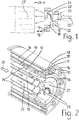
- an expansion chamber 21 open toward the burner mouth is arranged in the burner with an enlarged cross-section compared to the tube cross-sections.
- the lumped secondary fuels 25 blown in via the tubes 19, 20 are first allowed to exit into the expansion chamber 21, from which the lumped secondary fuels preheated there with prolonged residence time then enter the flame cone of the burner flame at a markedly reduced velocity at the burner mouth. while minimizing the risk of the lumps of secondary fuel particles moving past the flame.
- the amount of usable low-priced particulate secondary fuels such.
- waste plastic granules significantly increase as energy and part of the relatively expensive primary fuel, eg. B. save coal dust.
- the mixing of the blown lumped secondary fuels into the burner flame and their design can be further influenced by the fact that at the mouth of the secondary fuel tubes 19, 20 in the expansion chamber 21 a separate swirl generator 23 is arranged for the rotation of the secondary fuels already in the expansion chamber 21 Fig. 2 consists of this swirl generator 23 from one of the outlets of the secondary fuel tubes 19, 20 and flowed through by the secondary fuel component having circumferentially distributed swirl slots, which are flowed through by additional blown by the burner primary air, which introduced via the annular channel 24 in the burner is and transfers its angular momentum in the expansion chamber 21 to the blown lumped secondary fuels.
- This measure also contributes to the fact that the relatively large amount of lumped secondary fuels to be used does not undesirably pass the burner flame in the rotary kiln burner according to the invention but burns out in the burner flame.
- Fig. 1 In the schematic representation of Fig. 1 are introduced into the rotary kiln burner according to the invention lumped secondary fuels as in Fig. 2 symbolized by the big arrow 25. Further, there is shown schematically that the desired distance 26 of the beginning of the flame root 27 to the burner mouth in a range of about 300 to about 800 mm also with the help of the adjustable axial length of the expansion chamber 21 and the angular momentum of the blown secondary fuels and possibly in dependence on other parameters even during burner operation is adjustable.
- the rotary kiln burner according to the invention is suitable for the proportion of used relatively expensive primary fuel z.
- coal dust as solid fuel or oil and reduce the proportion of inexpensive alternative fuels such as lumpy waste fuels such.
Landscapes
- Engineering & Computer Science (AREA)
- Mechanical Engineering (AREA)
- General Engineering & Computer Science (AREA)
- Chemical & Material Sciences (AREA)
- Combustion & Propulsion (AREA)
- Environmental & Geological Engineering (AREA)
- Muffle Furnaces And Rotary Kilns (AREA)
- Incineration Of Waste (AREA)
Description
- Die Erfindung betrifft einen Drehofenbrenner mit einem innerhalb eines Brennertragrohres ringförmig angeordneten Kanal zum Transport eines Primärbrennstoffs, welcher durch eine Ringspaltdüse mit geringem nach außen divergierenden Winkel aus dem Drehofenbrenner ausströmt und sowohl von einem radial innen wie auch einem radial außen gelegenen Brennluftkanal umgeben ist, wobei beide Luftströme aus den Brennluftkanälen die Primärluft für den Drehofenbrenner bilden und wobei der radial innen liegende Brennluftkanal an seiner Ausmündung mit einem Drallerzeuger ausgestattet ist und der radial außen liegende Brennluftkanal Primärluft achsparallel einer Brennerflamme zuführt.
- Bei einer Zementklinkerproduktionslinie wird calciniertes Zementrohmehl in der Sinterzone eines Drehrohrofens zu Zementklinker gebrannt. Zur Beheizung des Drehrohrofens ist in das Ofenauslaufende durch das stationäre Ofenauslaufgehäuse hindurch eine lange Brennerlanze eingeführt, an deren Ausmündung die in die Lanze eingeführten Brennstoffe unter Bildung einer Brennerflamme verbrennen. Bei der Klinkermineralbildung im Drehrohrofen kommt es auf die richtige Temperatur, Länge und sonstige Gestaltung der Brennerflamme an. Die Entwicklung geht dahin, durch hochgradige Calcination des Zementrohmehls außerhalb des Drehrohrofens den Drehrohrofen selbst möglichst kurz zu bauen, so dass in Reaktion hierauf die Brennerflamme in der Regel möglichst kurz und heiß sein soll. Als Brennstoffe werden statt flüssige und gasförmige Brennstoffe immer häufiger Festbrennstoffe, insbesondere Kohlenstaub, aber in letzter Zeit auch pneumatisch transportierbare stückige Abfallbrennstoffe wie z. B. Abfallkunststoffgranulate etc. als Sekundärbrennstoffe eingesetzt.
- Bekannte Drehofenbrenner sind oft als sogenannte Dreikanalbrenner ausgebildet (z. B.
DE 43 19 363 A1 ), mit wenigstens drei zueinander konzentrischen Kanälen, d. h. durch den mittleren Brennerkanal strömt als Brennstoff der pneumatisch transportierte Kohlenstaub, der durch eine Ringspaltdüse austritt, wobei der ausströmende Kohlenstaub von radial innerer als auch von radial äußerer Primärluft als Brennluft umgeben ist. Die radial äußere Luft, auch Jetluft genannt, wird mittels einer Vielzahl im ringförmigen Jetluftkanal angeordneter einzelner Düsen in viele einzelne Hochgeschwindigkeits-Primärluftstrahlen unterteilt, die in ihrer Umgebung einer Unterdruckgebiet erzeugen, d. h. die vielen Hochgeschwindigkeits-Primärluftstrahlen dienen als Treibstrahlen nach dem Injektorprinzip, durch welches die große Masse der den Drehofenbrenner umgebenden, praktisch ruhenden heißen Sekundärluft von z. B. etwa 1000° C nach innen in Richtung zum Kern der Brennerflamme eingesaugt wird, wo eine intensive Durchmischung der heißen Sekundärluft mit dem durch die Ringspaltdüse austretenden Kohlenstaub stattfindet, der schnell und vollständig unter Ausbildung einer kurzen heißen Flamme verbrennen soll. - Bei dem bekannten Dreikanalbrenner wäre es nicht möglich, durch den Kohlenstaubkanal mit seiner Ringspaltdüse stückigen Sekundärbrennstoff einzublasen, welche die Ringspaltdüse verstopfen würden. Man hat daher bereits versucht, durch das Zentralrohr des Brenners, in welches ein zentraler Zündbrenner einsetzbar ist, stückigen Sekundärbrennstoff durchzublasen, der dann allerdings als kompakter Strahl austritt, in welchem der stückige Brennstoff sich wenig auffächert, im Drehrohrofen zu weit fliegt, eine zu lange Flamme bildet und nicht oder zu spät ausbrennt. Ferner hat man versucht, die eingeblasenen Sekundärbrennstoffe an der Mündung der Brennerlanze in Rotation zu versetzen, was zur Folge hat, dass besonders die großen und spezifisch schweren Sekundärbrennstoffstücke an die Peripherie geschleudert, jedenfalls aus dem Flammkegel herausgeschleudert werden, statt in der Flamme zu verbrennen.
- In der Druckschrift
AT 410 584 B - Der Erfindung liegt die Aufgabe zugrunde, einen Drehofenbrenner zu schaffen, bei dem sich der Mengenanteil an einzusetzenden preisgünstigen Sekundärbrennstoffen als Energieträger steigern lässt und Einfluss auf die Gestaltung der Brennerflamme genommen werden kann.
- Diese Aufgabe wird gemäß der Erfindung mit einem Drehofenbrenner mit den Merkmalen des Anspruchs 1 gelöst. Vorteilhafte Ausgestaltungen der Erfindung sind in den Unteransprüchen angegeben.
- Beim erfindungsgemäßen Brenner ist vor der Ausmündung des wenigstens einen Rohres zur Ausblasung der stückigen Sekundärbrennstoffe im Brenner eine zur Brennermündung hin offene Expansionskammer mit im Vergleich zu dem Sekundärbrennstoffrohr erweitertem Querschnitt angeordnet. Das heißt die pneumatisch transportierten über ein oder mehrere Einblasrohre eingeblasenen stückigen Sekundärbrennstoffe treten zunächst in eine im Querschnitt erweiterte Expansionskammer ein, aus welcher dann die mit verlängerter Verweilzeit voroxidierten stückigen Sekundärbrennstoffe an der Brennermündung mit erheblich reduzierter Geschwindigkeit in den Flammkegel der Brennerflamme eintreten. Die Gefahr, dass Partikel des Sekundärbrennstoffstrahls unverbrannt an der Brennerflamme vorbeifliegen, ist minimiert. Jedenfalls lässt sich beim erfindungsgemäßen Brenner der Mengenanteil an einsetzbaren preisgünstigen Sekundärbrennstoffen als Energieträger deutlich steigern und ein Teil des vergleichsweise teuren Primärbrennstoffs einsparen.
- Die axiale Länge der Expansionskammer ist durch Axialverschiebung des/der Sekundärbrennstoff-Rohre während des Brennerbetriebes variierbar. Damit kann auf das Volumen der Expansionskammer, auf die Voroxidation der stückigen Sekundärbrennstoffe in der Expansionskammer, auf die Strömungsgeschwindigkeits-Reduzierung in der Expansionskammer sowie auf den räumlichen Austrittswinkel des Sekundärbrennstoffstrahls Einfluss genommen werden in der Weise, dass die stückigen Sekundärbrennstoffe innerhalb der Brennerflamme mit der gewünschten Flammkonfiguration ausbrennen.
- Nach einem besonderen Merkmal der Erfindung kann an der Ausmündung des/der Sekundärbrennstoff-Rohre in die Expansionskammer ein eigener Drallerzeuger angeordnet sein zur Verdrallung der Sekundärbrennstoffe bereits in der Expansionskammer. Dabei kann der Drallerzeuger aus einem an die Ausmündung des/der Sekundärbrennstoff-Rohre angesetzten und von den Sekundärbrennstoffen durchströmten Bauteil bestehen, das über den Umfang verteilte Drallschlitze aufweist, die von zusätzlicher durch den Brenner geblasener Primärluft durchströmt sind, welch letztere ihren Drehimpuls in der Expansionskammer auf die ausgeblasenen Sekundärbrennstoffe überträgt. Durch den Drehimpuls der stückigen Sekundärbrennstoffe kann deren Einmischung in die Brennerflamme begünstigt werden. Außerdem kann auch damit immer die jeweils gewünschte Brennerflammengestalt eingestellt werden.
- Die Erfindung und deren weitere Merkmale und Vorteile werden anhand der in den Figuren schematisch dargestellten Ausführungsbeispiele näher erläutert.
- Es zeigt:
- Fig. 1:
- schematisch einen Axialschnitt durch das Zentrum der Mündung des erfindungsgemäßen Drehofenbrenners mit eingesetzten stückigen Sekundärbrennstoffen, und
- Fig. 2:
- vergrößert herausgezeichnet und perspektivisch im Detail den Axialschnitt durch die Brennermündung, teilweise in Stirnansicht.
- Beschrieben anhand der
Figur 2 ist der erfindungsgemäße Drehofenbrenner zunächst ein Dreikanalbrenner mit einem ringförmig angeordneten Kanal 10 zum pneumatischen Transport eines feinkörnigen Festbrennstoffs wie z. B. Kohlenstaub, der durch eine Ringspaltdüse 11 mit geringem nach außen divergierenden Winkel ausströmt. Der Kohlenstaubkanal 10 ist konzentrisch sowohl von einem radial innen als auch von einem radial außen gelegenen Brennluftkanal umgeben, wobei diese Brennluftströme die Primärluft für den Brenner bilden. Der konzentrisch innerhalb des Kohlenstaubkanals 10 angeordnete Primärluftkanal 12 ist an seiner Ausmündung mit einem Drallerzeuger 13 z. B. mit Drallschlitzen ausgestattet, so dass dieser radial innen gelegene Primärluftkanal auch Drallluftkanal genannt wird. Die radial äußere Primärluft, auch Jetluft genannt, wird über achsparallel um die Brennerachse verteilt angeordnete Jetluftrohre 14 zugeführt und sie tritt mit hoher Geschwindigkeit in Form von Düsenstrahlen aus einzelnen um den Umfang der Brennermündung verteilt angeordneten Jetluftdüsen 15 aus, z. B. 12 Stück. Die Hochgeschwindigkeits-Jetluftstrahlen, die in der Lage sind, möglichst viel der den Drehofenbrenner im Drehrohrofen umgebenden heißen Sekundärluft von z. B. 1000° C in den Kern der Brennerflamme zwecks schneller und vollständiger Brennstoffverbrennung einzusaugen, sollen den Brennstoffkegel bzw. die Brennerflamme an einer optimalen Stelle zwecks Erzielung großer Flammenturbulenzen treffen. - Im Ringraum zwischen dem außen liegenden Brennertragrohr 16 und dem konzentrisch dazu angeordneten Kohlenstaubrohr 17 wird Kühlluft durch den Brenner geblasen, die an der Brennermündung im Bereich zwischen den benachbarten Jetluftdüsen 15 ausströmt, wo dann die an der Brennerlanze erhitzte Kühlluft einen Anteil der Primärluft bildet. Der ringförmige Kühlluftkanal ist mit der Bezugsziffer 18 bezeichnet. Das Brennertragrohr 16 ist jedenfalls im vorderen Brennerlanzenbereich durch eine aufgebrachte in
Fig. 2 nicht dargestellte Feuerfestmasse geschützt. - In das Zentralrohr des Brenners, in welches bei einem konventionellen Brenner ein zentraler Zündbrenner einsetzbar ist, sind gemäß Ausführungsbeispiel der
Fig. 2 z. B. zwei Rohre 19, 20 zum pneumatischen Transport und Ausblasen von stückigen Alternativbrennstoffen bzw. Sekundärbrennstoffen an der Brennermündung eingeführt. Vor der Ausmündung der Rohre 19, 20 zur Ausblasung der Sekundärbrennstoffe ist im Brenner eine zur Brennermündung hin offene Expansionskammer 21 mit im Vergleich zu den Rohrquerschnitten erweitertem Querschnitt angeordnet. Das heißt beim erfindungsgemäßen Drehofenbrenner lässt man die über die Rohre 19, 20 eingeblasenen stückigen Sekundärbrennstoffe 25 zunächst in die Expansionskammer 21 austreten, aus welcher dann die dort mit verlängerter Verweilzeit voroxidierten stückigen Sekundärbrennstoffe mit deutlich reduzierter Geschwindigkeit an der Brennermündung in den Flammkegel der Brennerflamme eintreten, wobei die Gefahr des Vorbeifliegens stückiger Sekundärbrennstoffpartikel an der Flamme minimiert ist. Damit lässt sich beim erfindungsgemäßen Drehofenbrenner der Mengenanteil von einsetzbaren preisgünstigen stückigen Sekundärbrennstoffen wie z. B. Abfallkunststoffgranulate als Energieträger erheblich steigern und ein Teil des vergleichsweise teuren Primärbrennstoffs, z. B. Kohlenstaub einsparen. - Durch eine in
Fig. 1 mit dem Doppelpfeil 22 angezeigte Axialverschiebung der Sekundärbrennstoff-Rohre 19, 20 kann die axiale Länge und das Volumen der Expansionskammer 21 während des Brennerbetriebes variiert werden. Auf diese Weise kann Einfluss genommen werden auf die Austrittsgeschwindigkeit, Flugweite und Voroxidation der an der Brennermündung ausgeblasenen stückigen Sekundärbrennstoffpartikel sowie auch auf die Gestaltung der Brennerflamme. - Das Einmischen der ausgeblasenen stückigen Sekundärbrennstoffe in die Brennerflamme sowie deren Gestaltung können noch dadurch beeinflusst werden, dass an der Ausmündung der Sekundärbrennstoffrohre 19, 20 in die Expansionskammer 21 ein eigener Drallerzeuger 23 angeordnet ist zur Verdrallung der Sekundärbrennstoffe bereits in der Expansionskammer 21. Gemäß Ausführungsbeispiel der
Fig. 2 besteht dieser Drallerzeuger 23 aus einem an die Ausmündungen der Sekundärbrennstoffrohre 19, 20 angesetzten und von den Sekundärbrennstoffen durchströmten Bauteil, das über den Umfang verteilte Drallschlitze aufweist, die von zusätzlicher durch den Brenner geblasener Primärluft durchströmt sind, die über den Ringkanal 24 in den Brenner eingeführt wird und die ihren Drehimpuls in der Expansionskammer 21 auf die ausgeblasenen stückigen Sekundärbrennstoffe überträgt. Auch diese Maßnahme trägt dazu bei, dass beim erfindungsgemäßen Drehofenbrenner die vergleichsweise große Menge an einzusetzenden stückigen Sekundärbrennstoffen nicht in unerwünschter Weise an der Brennerflamme vorbeifliegt, sondern in der Brennerflamme ausbrennt. - In der schematischen Darstellung der
Fig. 1 sind die in den erfindungsgemäßen Drehofenbrenner eingeführten stückigen Sekundärbrennstoffe wie beiFig. 2 mit dem großen Pfeil 25 symbolisiert. Ferner ist dort schematisch dargestellt, dass der gewünschte Abstand 26 des Beginns der Flammenwurzel 27 zur Brennermündung in einem Bereich von etwa 300 bis etwa 800 mm auch mit Hilfe der einstellbaren axialen Länge der Expansionskammer 21 sowie des Drehimpulses der ausgeblasenen Sekundärbrennstoffe und ggf. in Abhängigkeit von weiteren Parametern auch während des Brennerbetriebes einstellbar ist. - In jedem Fall ist der erfindungsgemäße Drehofenbrenner dazu geeignet, den Mengenanteil an eingesetztem relativ teurem Primärbrennstoff z. B. Kohlenstaub als Festbrennstoff oder auch Öl zu reduzieren und dafür den Mengenanteil an preisgünstigen Alternativbrennstoffen wie stückige Abfallbrennstoffe wie z. B. Abfallkunststoffe, pneumatisch transportierbare Klärschlämme etc. zu erhöhen.
Claims (3)
- Drehofenbrenner- mit einem innerhalb eines Brennertragrohres (16) ringförmig angeordneten Kanal (10) zum Transport eines Primärbrennstoffs,dadurch gekennzeichnet, dass- welcher durch eine Ringspaltdüse (11) mit geringem nach außen divergierenden Winkel aus dem Drehofenbrenner ausströmt und- sowohl von einem radial innen- wie auch einem radial außen gelegenen Brennluftkanal konzentrisch umgeben ist,- wobei beide Luftströme aus den Brennluftkanälen (12, 14) die Primärluft für den Drehofenbrenner bilden und- wobei der radial innen liegende Brennluftkanal (12) an seiner Ausmündung mit einem Drallerzeuger (13) ausgestattet ist und- der radial außen liegende Brennluftkanal Primärluft achsparallel einer Brennerflamme zuführt, wobei die Primärluft über achsparallel um die Brennerachse verteilt angeordnete Jetluftrohre (14) zugeführt wird, und mit hoher Geschwindigkeit in Form von Düsenstrahlen aus einzelnen um den Umfang der Brennermündung verteilt angeordneten Jetluftdüse (15) austritt,- in einem Zentralrohr des Drehofenbrenners mindestens ein Rohr (19, 20) zum pneumatischen Transport und Ausblasen von stückigen Sekundärbrennstoffen (25) vorgesehen ist und- in einer Expansionskammer (21) mit im Vergleich zu dem Querschnitt des mindestens einen Rohrs (19, 20) erweitertem Querschnitt mündet und- dass die axiale Länge und das Volumen der Expansionskammer (21) während des Betriebes des Drehofenbrenners durch Axialverschiebung des / der Sekundärbrennstoff-Rohre (19, 20) variierbar sind,- wobei die mindestens aus einen Rohr (19, 20) ausgeblasenen, stückigen Sekundärbrennstoffe (25) durch die Wirkung der Expansionskammer (21) mit deutlich reduzierter Geschwindigkeit in den Flammkegel der Brennerflamme eintreten.
- Drehofenbrenner nach Anspruch 1,
dadurch gekennzeichnet, dass an der Ausmündung des mindestens einen Rohres (19, 20) in die Expansionskammer (21) ein Drallerzeuger (23) zur Verdrallung der Sekundärbrennstoffe bereits in der Expansionskammer (21) angeordnet ist. - Drehofenbrenner nach Anspruch 2,
dadurch gekennzeichnet, dass der Drallerzeuger (23) aus einem an die Ausmündungen des mindestens einen Rohres (19, 20) angesetzten und von den Sekundärbrennstoffen durchströmten Bauteil besteht, das über den Umfang verteilte Drallschlitze aufweist, die von zusätzlicher durch den Brenner geblasener Primärluft (24) durchströmt sind, welch letztere ihren Drehimpuls in der Expansionskammer (21) auf die ausgeblasenen Sekundärbrennstoffe überträgt.
Priority Applications (1)
| Application Number | Priority Date | Filing Date | Title |
|---|---|---|---|
| PL07856970T PL2102549T3 (pl) | 2006-12-22 | 2007-12-20 | Palnik pieca obrotowego |
Applications Claiming Priority (2)
| Application Number | Priority Date | Filing Date | Title |
|---|---|---|---|
| DE102006060867.4A DE102006060867B4 (de) | 2006-12-22 | 2006-12-22 | Drehofenbrenner |
| PCT/EP2007/011247 WO2008077576A1 (de) | 2006-12-22 | 2007-12-20 | Drehofenbrenner |
Publications (2)
| Publication Number | Publication Date |
|---|---|
| EP2102549A1 EP2102549A1 (de) | 2009-09-23 |
| EP2102549B1 true EP2102549B1 (de) | 2016-12-07 |
Family
ID=39278331
Family Applications (1)
| Application Number | Title | Priority Date | Filing Date |
|---|---|---|---|
| EP07856970.4A Active EP2102549B1 (de) | 2006-12-22 | 2007-12-20 | Drehofenbrenner |
Country Status (5)
| Country | Link |
|---|---|
| US (1) | US8393893B2 (de) |
| EP (1) | EP2102549B1 (de) |
| DE (1) | DE102006060867B4 (de) |
| PL (1) | PL2102549T3 (de) |
| WO (1) | WO2008077576A1 (de) |
Families Citing this family (15)
| Publication number | Priority date | Publication date | Assignee | Title |
|---|---|---|---|---|
| DE102006060869A1 (de) * | 2006-12-22 | 2008-06-26 | Khd Humboldt Wedag Gmbh | Verfahren zur Regelung des Betriebes eines Drehofenbrenners |
| DE202008009650U1 (de) * | 2008-07-18 | 2009-11-26 | Ammann Schweiz Ag | Mehrstoff-Brenner |
| EP2312215A1 (de) * | 2008-10-01 | 2011-04-20 | Siemens Aktiengesellschaft | Brenner und Verfahren zum Betrieb eines Brenners |
| DE102010061496A1 (de) * | 2010-12-22 | 2012-06-28 | Thyssenkrupp Polysius Ag | Rohrförmiger Brenner sowie Verfahren zum Betreiben eines rohrförmigen Brenners |
| CN103807869B (zh) * | 2012-11-08 | 2016-03-30 | 烟台龙源电力技术股份有限公司 | 一种用于锅炉的燃尽风喷口及锅炉 |
| DE102013004016A1 (de) * | 2013-03-08 | 2014-09-11 | Messer Austria Gmbh | Mehrstoffbrenner und Verfahren zum Beheizen eines Ofenraums |
| EP3350513A1 (de) * | 2015-07-31 | 2018-07-25 | Nuvera Fuel Cells, LLC | Brenneranordnung mit geringen nox-emissionen |
| MX2018012055A (es) * | 2016-05-11 | 2019-01-10 | Dynamis Engenharia E Comercio Ltda | Metodo para incrementar la eficiencia en quemadores y quemador. |
| CN106361121B (zh) * | 2016-11-02 | 2018-01-05 | 吉林省福泰厨具有限公司 | 一种无烟焚烧炉 |
| US11555612B2 (en) * | 2017-11-29 | 2023-01-17 | Babcock Power Services, Inc. | Dual fuel direct ignition burners |
| IL266905B2 (en) * | 2019-05-27 | 2024-04-01 | Babcock Power Services Inc | Dual fuel direct ignition burners |
| JP6704541B6 (ja) * | 2019-08-14 | 2020-07-01 | 太平洋セメント株式会社 | 可燃性廃棄物吹込装置及びその運転方法 |
| US11421871B2 (en) * | 2019-08-14 | 2022-08-23 | Taiheiyo Cement Corporation | Combustible waste injection device and method for operating the same |
| AT524888A1 (de) * | 2021-03-23 | 2022-10-15 | Mme Eng E U | Ultra-Low-NOx-Brenner |
| US12158268B2 (en) * | 2021-06-08 | 2024-12-03 | Forney Corporation | High-capacity igniter |
Family Cites Families (28)
| Publication number | Priority date | Publication date | Assignee | Title |
|---|---|---|---|---|
| DE1096530B (de) * | 1957-12-20 | 1961-01-05 | Borsig Ag | Mischbrenner mit axial verschiebbarer Regeleinrichtung an der Brennermuendung |
| DE1451440A1 (de) * | 1963-08-06 | 1969-03-06 | Unitherm Deutsche Ges Fuer Uni | OElbrenner |
| FR1536372A (fr) * | 1967-07-04 | 1968-08-27 | Union Generale De Distrib De P | Appareillage à brûleur gazéifiant une émulsion pulvérisée de combustible liquide |
| DE2144481A1 (de) * | 1971-09-06 | 1973-03-15 | Balcke Maschbau Ag | Brenner, insbesondere fuer gasfoermige brennstoffe |
| US4517905A (en) * | 1983-02-10 | 1985-05-21 | Prm Energy Systems, Inc. | Particulate waste product combustion system |
| DE3518080A1 (de) * | 1985-05-20 | 1986-11-20 | Stubinen Utveckling AB, Stockholm | Verfahren und vorrichtung zum verbrennen fluessiger und/oder fester brennstoffe in pulverisierter form |
| US4775314A (en) * | 1985-05-20 | 1988-10-04 | Shell Oil Company | Coal gasification burner |
| DD290334A7 (de) * | 1988-10-21 | 1991-05-29 | Zementwerke Bernburg Gmbh I.G.,De | Steuerbarer gasbrenner fuer drehrohroefen |
| DE3837586A1 (de) * | 1988-11-05 | 1990-05-10 | Krupp Koppers Gmbh | Vergasungsbrenner fuer eine anlage fuer die vergasung von festen brennstoffen |
| US5178533A (en) * | 1989-10-04 | 1993-01-12 | Enterprise Generale De Chauffage Industries Pillard | Process for exploiting a burner and burners for a rotary tubular furnance |
| FR2656676B1 (fr) * | 1989-12-28 | 1994-07-01 | Inst Francais Du Petrole | Bruleur industriel a combustible liquide a faible emission d'oxyde d'azote, ledit bruleur generant plusieurs flammes elementaires et son utilisation. |
| EP0445938B1 (de) * | 1990-03-07 | 1996-06-26 | Hitachi, Ltd. | Kohlenstaubbrenner, Kohlenstaubkessel und Verfahren zum Verbrennen von Kohlenstaub |
| US5199355A (en) * | 1991-08-23 | 1993-04-06 | The Babcock & Wilcox Company | Low nox short flame burner |
| DE4319363A1 (de) | 1993-06-11 | 1994-12-15 | Kloeckner Humboldt Deutz Ag | Drehofenbrenner |
| AT402963B (de) * | 1995-09-07 | 1997-10-27 | Voest Alpine Ind Anlagen | Verfahren zum verbrennen von brennstoff |
| WO1998029690A1 (en) * | 1996-12-27 | 1998-07-09 | Sumitomo Osaka Cement Co., Ltd. | Device and method for combustion of fuel |
| JP2000327378A (ja) * | 1999-05-19 | 2000-11-28 | Ishikawajima Harima Heavy Ind Co Ltd | 難燃性燃料用仮焼炉 |
| JP4341131B2 (ja) * | 2000-01-19 | 2009-10-07 | Jfeスチール株式会社 | 微粉炭吹込みバーナー |
| US6315551B1 (en) * | 2000-05-08 | 2001-11-13 | Entreprise Generale De Chauffage Industriel Pillard | Burners having at least three air feed ducts, including an axial air duct and a rotary air duct concentric with at least one fuel feed, and a central stabilizer |
| US6461148B1 (en) * | 2000-09-28 | 2002-10-08 | Mcdermott Technology, Inc. | Compact, high-temperature, low-flow rate, liquid fuel-fired burner |
| JP4550989B2 (ja) * | 2000-11-01 | 2010-09-22 | 大同特殊鋼株式会社 | 粉体溶融バーナ |
| AU2002250671A1 (en) * | 2000-11-27 | 2002-06-03 | Linde Aktiengesellschaft | Burner and method for the chemical reaction of two gas streams |
| AT410584B (de) * | 2001-05-21 | 2003-06-25 | Unitherm Cemcon Feuerungsanlag | Brenner für grossfeuerungen |
| AT411928B (de) * | 2001-12-21 | 2004-07-26 | Unitherm Cemcon Feuerungsanlag | Brenner, insbesondere für drehrohröfen |
| US6968692B2 (en) * | 2002-04-26 | 2005-11-29 | Rolls-Royce Corporation | Fuel premixing module for gas turbine engine combustor |
| US6969249B2 (en) * | 2003-05-02 | 2005-11-29 | Hauck Manufacturing, Inc. | Aggregate dryer burner with compressed air oil atomizer |
| DE102004010063A1 (de) * | 2004-03-02 | 2005-09-22 | Khd Humboldt Wedag Ag | Drehofenbrenner |
| JP4922400B2 (ja) * | 2007-05-30 | 2012-04-25 | 大陽日酸株式会社 | 無機質球状化粒子製造用バーナ |
-
2006
- 2006-12-22 DE DE102006060867.4A patent/DE102006060867B4/de active Active
-
2007
- 2007-12-20 US US12/520,661 patent/US8393893B2/en active Active
- 2007-12-20 EP EP07856970.4A patent/EP2102549B1/de active Active
- 2007-12-20 WO PCT/EP2007/011247 patent/WO2008077576A1/de not_active Ceased
- 2007-12-20 PL PL07856970T patent/PL2102549T3/pl unknown
Non-Patent Citations (1)
| Title |
|---|
| None * |
Also Published As
| Publication number | Publication date |
|---|---|
| US8393893B2 (en) | 2013-03-12 |
| DE102006060867A1 (de) | 2008-06-26 |
| US20100019063A1 (en) | 2010-01-28 |
| PL2102549T3 (pl) | 2017-05-31 |
| WO2008077576A1 (de) | 2008-07-03 |
| EP2102549A1 (de) | 2009-09-23 |
| DE102006060867B4 (de) | 2020-07-02 |
Similar Documents
| Publication | Publication Date | Title |
|---|---|---|
| EP2102549A1 (de) | Drehofenbrenner | |
| EP2102550B1 (de) | Verfahren zur Regelung des Betriebes eines Drehofenbrenners | |
| DE69730702T3 (de) | Vorrichtung und verfahren zur verbrennung von brennstoff | |
| EP2225488B1 (de) | Vormischbrenner für eine gasturbine | |
| EP2009351B1 (de) | Kohlenstaubbrenner zur Verfeuerung von in Dichtstromförderung zugeführtem Brennstoff | |
| EP0401529A1 (de) | Brennkammer einer Gasturbine | |
| AT411363B (de) | Einrichtung zum schmelzen von stäuben | |
| EP1741977B1 (de) | Kohlenstaubbrenner für niedrige NOx-Emissionen | |
| WO2012084575A2 (de) | Rohrförmiger brenner sowie verfahren zum betreiben eines rohrförmigen brenners | |
| EP1725811B1 (de) | Drehofenbrenner | |
| EP1183482B1 (de) | Rohrförmiger brenner für industrieöfen | |
| DE202008009650U1 (de) | Mehrstoff-Brenner | |
| EP1352197B1 (de) | Brenner zur verbrennung von staubförmigem brennstoff | |
| DE102017118166B4 (de) | Brennerkopf, Brennersystem und Verwendung des Brennersystems | |
| DE102004059679B4 (de) | Rundbrenner zur Verbrennung von staubförmigem Brennstoff | |
| DE69712452T2 (de) | Brenner mit hoher Wärmeabgabe | |
| EP2252831B1 (de) | Brenneranordnung sowie anwendung einer solchen brenner-anordnung | |
| EP0619458B1 (de) | Drehofenbrenner für feinkörnigen Festbrennstoff | |
| DE2364053C2 (de) | Feuerungsanlage | |
| DE60010174T2 (de) | Mehrstoffbrenner | |
| EP3267104A1 (de) | Brenner und verfahren zur optimierten verbrennung grober, partikelförmiger brennstoffe, insbesondere biomasse | |
| DE3205255C2 (de) | Verfahren zum Brennen von mineralischen Rohstoffen sowie Vorrichtung insbesondere zur Durchführung des Verfahrens | |
| WO2008020299A2 (de) | Einrichtung zum versprühen von schlämmen in brennöfen | |
| DD239346A1 (de) | Vorrichtung zur brennstoffzufuehrung in eine wirbelschicht |
Legal Events
| Date | Code | Title | Description |
|---|---|---|---|
| PUAI | Public reference made under article 153(3) epc to a published international application that has entered the european phase |
Free format text: ORIGINAL CODE: 0009012 |
|
| 17P | Request for examination filed |
Effective date: 20090619 |
|
| AK | Designated contracting states |
Kind code of ref document: A1 Designated state(s): AT BE BG CH CY CZ DE DK EE ES FI FR GB GR HU IE IS IT LI LT LU LV MC MT NL PL PT RO SE SI SK TR |
|
| AX | Request for extension of the european patent |
Extension state: AL BA HR MK RS |
|
| 17Q | First examination report despatched |
Effective date: 20150316 |
|
| GRAP | Despatch of communication of intention to grant a patent |
Free format text: ORIGINAL CODE: EPIDOSNIGR1 |
|
| INTG | Intention to grant announced |
Effective date: 20160919 |
|
| GRAS | Grant fee paid |
Free format text: ORIGINAL CODE: EPIDOSNIGR3 |
|
| GRAA | (expected) grant |
Free format text: ORIGINAL CODE: 0009210 |
|
| AK | Designated contracting states |
Kind code of ref document: B1 Designated state(s): AT BE BG CH CY CZ DE DK EE ES FI FR GB GR HU IE IS IT LI LT LU LV MC MT NL PL PT RO SE SI SK TR |
|
| AX | Request for extension of the european patent |
Extension state: AL BA HR MK RS |
|
| REG | Reference to a national code |
Ref country code: GB Ref legal event code: FG4D Free format text: NOT ENGLISH |
|
| REG | Reference to a national code |
Ref country code: CH Ref legal event code: EP Ref country code: AT Ref legal event code: REF Ref document number: 852073 Country of ref document: AT Kind code of ref document: T Effective date: 20161215 |
|
| REG | Reference to a national code |
Ref country code: IE Ref legal event code: FG4D Free format text: LANGUAGE OF EP DOCUMENT: GERMAN |
|
| REG | Reference to a national code |
Ref country code: DE Ref legal event code: R096 Ref document number: 502007015316 Country of ref document: DE |
|
| REG | Reference to a national code |
Ref country code: FR Ref legal event code: PLFP Year of fee payment: 10 |
|
| PG25 | Lapsed in a contracting state [announced via postgrant information from national office to epo] |
Ref country code: LV Free format text: LAPSE BECAUSE OF FAILURE TO SUBMIT A TRANSLATION OF THE DESCRIPTION OR TO PAY THE FEE WITHIN THE PRESCRIBED TIME-LIMIT Effective date: 20161207 |
|
| REG | Reference to a national code |
Ref country code: LT Ref legal event code: MG4D |
|
| REG | Reference to a national code |
Ref country code: NL Ref legal event code: MP Effective date: 20161207 |
|
| PG25 | Lapsed in a contracting state [announced via postgrant information from national office to epo] |
Ref country code: LT Free format text: LAPSE BECAUSE OF FAILURE TO SUBMIT A TRANSLATION OF THE DESCRIPTION OR TO PAY THE FEE WITHIN THE PRESCRIBED TIME-LIMIT Effective date: 20161207 Ref country code: GR Free format text: LAPSE BECAUSE OF FAILURE TO SUBMIT A TRANSLATION OF THE DESCRIPTION OR TO PAY THE FEE WITHIN THE PRESCRIBED TIME-LIMIT Effective date: 20170308 Ref country code: SE Free format text: LAPSE BECAUSE OF FAILURE TO SUBMIT A TRANSLATION OF THE DESCRIPTION OR TO PAY THE FEE WITHIN THE PRESCRIBED TIME-LIMIT Effective date: 20161207 |
|
| PG25 | Lapsed in a contracting state [announced via postgrant information from national office to epo] |
Ref country code: BE Free format text: LAPSE BECAUSE OF NON-PAYMENT OF DUE FEES Effective date: 20161231 Ref country code: FI Free format text: LAPSE BECAUSE OF FAILURE TO SUBMIT A TRANSLATION OF THE DESCRIPTION OR TO PAY THE FEE WITHIN THE PRESCRIBED TIME-LIMIT Effective date: 20161207 Ref country code: ES Free format text: LAPSE BECAUSE OF FAILURE TO SUBMIT A TRANSLATION OF THE DESCRIPTION OR TO PAY THE FEE WITHIN THE PRESCRIBED TIME-LIMIT Effective date: 20161207 |
|
| PG25 | Lapsed in a contracting state [announced via postgrant information from national office to epo] |
Ref country code: NL Free format text: LAPSE BECAUSE OF FAILURE TO SUBMIT A TRANSLATION OF THE DESCRIPTION OR TO PAY THE FEE WITHIN THE PRESCRIBED TIME-LIMIT Effective date: 20161207 |
|
| REG | Reference to a national code |
Ref country code: DE Ref legal event code: R119 Ref document number: 502007015316 Country of ref document: DE |
|
| PG25 | Lapsed in a contracting state [announced via postgrant information from national office to epo] |
Ref country code: EE Free format text: LAPSE BECAUSE OF FAILURE TO SUBMIT A TRANSLATION OF THE DESCRIPTION OR TO PAY THE FEE WITHIN THE PRESCRIBED TIME-LIMIT Effective date: 20161207 Ref country code: SK Free format text: LAPSE BECAUSE OF FAILURE TO SUBMIT A TRANSLATION OF THE DESCRIPTION OR TO PAY THE FEE WITHIN THE PRESCRIBED TIME-LIMIT Effective date: 20161207 Ref country code: IS Free format text: LAPSE BECAUSE OF FAILURE TO SUBMIT A TRANSLATION OF THE DESCRIPTION OR TO PAY THE FEE WITHIN THE PRESCRIBED TIME-LIMIT Effective date: 20170407 Ref country code: RO Free format text: LAPSE BECAUSE OF FAILURE TO SUBMIT A TRANSLATION OF THE DESCRIPTION OR TO PAY THE FEE WITHIN THE PRESCRIBED TIME-LIMIT Effective date: 20161207 |
|
| PG25 | Lapsed in a contracting state [announced via postgrant information from national office to epo] |
Ref country code: BG Free format text: LAPSE BECAUSE OF FAILURE TO SUBMIT A TRANSLATION OF THE DESCRIPTION OR TO PAY THE FEE WITHIN THE PRESCRIBED TIME-LIMIT Effective date: 20170307 Ref country code: PT Free format text: LAPSE BECAUSE OF FAILURE TO SUBMIT A TRANSLATION OF THE DESCRIPTION OR TO PAY THE FEE WITHIN THE PRESCRIBED TIME-LIMIT Effective date: 20170407 Ref country code: IT Free format text: LAPSE BECAUSE OF FAILURE TO SUBMIT A TRANSLATION OF THE DESCRIPTION OR TO PAY THE FEE WITHIN THE PRESCRIBED TIME-LIMIT Effective date: 20161207 |
|
| PG25 | Lapsed in a contracting state [announced via postgrant information from national office to epo] |
Ref country code: MC Free format text: LAPSE BECAUSE OF FAILURE TO SUBMIT A TRANSLATION OF THE DESCRIPTION OR TO PAY THE FEE WITHIN THE PRESCRIBED TIME-LIMIT Effective date: 20161207 |
|
| REG | Reference to a national code |
Ref country code: IE Ref legal event code: MM4A |
|
| PLBE | No opposition filed within time limit |
Free format text: ORIGINAL CODE: 0009261 |
|
| STAA | Information on the status of an ep patent application or granted ep patent |
Free format text: STATUS: NO OPPOSITION FILED WITHIN TIME LIMIT |
|
| PG25 | Lapsed in a contracting state [announced via postgrant information from national office to epo] |
Ref country code: LU Free format text: LAPSE BECAUSE OF NON-PAYMENT OF DUE FEES Effective date: 20161220 |
|
| 26N | No opposition filed |
Effective date: 20170908 |
|
| PG25 | Lapsed in a contracting state [announced via postgrant information from national office to epo] |
Ref country code: IE Free format text: LAPSE BECAUSE OF NON-PAYMENT OF DUE FEES Effective date: 20161220 Ref country code: SI Free format text: LAPSE BECAUSE OF FAILURE TO SUBMIT A TRANSLATION OF THE DESCRIPTION OR TO PAY THE FEE WITHIN THE PRESCRIBED TIME-LIMIT Effective date: 20161207 Ref country code: DE Free format text: LAPSE BECAUSE OF NON-PAYMENT OF DUE FEES Effective date: 20170701 Ref country code: DK Free format text: LAPSE BECAUSE OF FAILURE TO SUBMIT A TRANSLATION OF THE DESCRIPTION OR TO PAY THE FEE WITHIN THE PRESCRIBED TIME-LIMIT Effective date: 20161207 |
|
| REG | Reference to a national code |
Ref country code: FR Ref legal event code: PLFP Year of fee payment: 11 |
|
| REG | Reference to a national code |
Ref country code: BE Ref legal event code: MM Effective date: 20161231 |
|
| PG25 | Lapsed in a contracting state [announced via postgrant information from national office to epo] |
Ref country code: CY Free format text: LAPSE BECAUSE OF FAILURE TO SUBMIT A TRANSLATION OF THE DESCRIPTION OR TO PAY THE FEE WITHIN THE PRESCRIBED TIME-LIMIT Effective date: 20161207 Ref country code: HU Free format text: LAPSE BECAUSE OF FAILURE TO SUBMIT A TRANSLATION OF THE DESCRIPTION OR TO PAY THE FEE WITHIN THE PRESCRIBED TIME-LIMIT; INVALID AB INITIO Effective date: 20071220 |
|
| PG25 | Lapsed in a contracting state [announced via postgrant information from national office to epo] |
Ref country code: MT Free format text: LAPSE BECAUSE OF FAILURE TO SUBMIT A TRANSLATION OF THE DESCRIPTION OR TO PAY THE FEE WITHIN THE PRESCRIBED TIME-LIMIT Effective date: 20161207 |
|
| P01 | Opt-out of the competence of the unified patent court (upc) registered |
Effective date: 20230627 |
|
| REG | Reference to a national code |
Ref country code: CH Ref legal event code: U11 Free format text: ST27 STATUS EVENT CODE: U-0-0-U10-U11 (AS PROVIDED BY THE NATIONAL OFFICE) Effective date: 20260101 |
|
| PGFP | Annual fee paid to national office [announced via postgrant information from national office to epo] |
Ref country code: GB Payment date: 20251219 Year of fee payment: 19 |
|
| PGFP | Annual fee paid to national office [announced via postgrant information from national office to epo] |
Ref country code: AT Payment date: 20251222 Year of fee payment: 19 |
|
| PGFP | Annual fee paid to national office [announced via postgrant information from national office to epo] |
Ref country code: FR Payment date: 20251222 Year of fee payment: 19 |
|
| PGFP | Annual fee paid to national office [announced via postgrant information from national office to epo] |
Ref country code: TR Payment date: 20251215 Year of fee payment: 19 |
|
| PGFP | Annual fee paid to national office [announced via postgrant information from national office to epo] |
Ref country code: CZ Payment date: 20251217 Year of fee payment: 19 |
|
| PGFP | Annual fee paid to national office [announced via postgrant information from national office to epo] |
Ref country code: PL Payment date: 20251216 Year of fee payment: 19 |
|
| PGFP | Annual fee paid to national office [announced via postgrant information from national office to epo] |
Ref country code: CH Payment date: 20260101 Year of fee payment: 19 |