EP2096523B1 - Lokalisierungssystem mit virtuellem Berührungsbildschirm - Google Patents
Lokalisierungssystem mit virtuellem Berührungsbildschirm Download PDFInfo
- Publication number
- EP2096523B1 EP2096523B1 EP09250552.8A EP09250552A EP2096523B1 EP 2096523 B1 EP2096523 B1 EP 2096523B1 EP 09250552 A EP09250552 A EP 09250552A EP 2096523 B1 EP2096523 B1 EP 2096523B1
- Authority
- EP
- European Patent Office
- Prior art keywords
- signals
- responsively
- display device
- magnetic
- joystick
- Prior art date
- Legal status (The legal status is an assumption and is not a legal conclusion. Google has not performed a legal analysis and makes no representation as to the accuracy of the status listed.)
- Active
Links
- 230000033001 locomotion Effects 0.000 claims description 7
- 210000003484 anatomy Anatomy 0.000 claims description 5
- 230000037431 insertion Effects 0.000 claims 2
- 238000003780 insertion Methods 0.000 claims 2
- 238000000034 method Methods 0.000 description 26
- 238000003384 imaging method Methods 0.000 description 11
- 241001422033 Thestylus Species 0.000 description 6
- 238000012545 processing Methods 0.000 description 6
- 230000006870 function Effects 0.000 description 4
- 230000004044 response Effects 0.000 description 4
- 238000002679 ablation Methods 0.000 description 3
- 230000003190 augmentative effect Effects 0.000 description 3
- 230000008859 change Effects 0.000 description 3
- 230000000694 effects Effects 0.000 description 3
- 238000013507 mapping Methods 0.000 description 3
- 230000008569 process Effects 0.000 description 3
- 210000001519 tissue Anatomy 0.000 description 3
- 238000002604 ultrasonography Methods 0.000 description 3
- 238000002059 diagnostic imaging Methods 0.000 description 2
- 229910003460 diamond Inorganic materials 0.000 description 2
- 239000010432 diamond Substances 0.000 description 2
- 238000006073 displacement reaction Methods 0.000 description 2
- 210000000056 organ Anatomy 0.000 description 2
- 230000001225 therapeutic effect Effects 0.000 description 2
- 230000017531 blood circulation Effects 0.000 description 1
- 230000000747 cardiac effect Effects 0.000 description 1
- 238000004883 computer application Methods 0.000 description 1
- 238000004590 computer program Methods 0.000 description 1
- 230000001419 dependent effect Effects 0.000 description 1
- 238000003745 diagnosis Methods 0.000 description 1
- 238000010586 diagram Methods 0.000 description 1
- 230000009977 dual effect Effects 0.000 description 1
- 238000003708 edge detection Methods 0.000 description 1
- 230000005672 electromagnetic field Effects 0.000 description 1
- 231100001261 hazardous Toxicity 0.000 description 1
- 210000005003 heart tissue Anatomy 0.000 description 1
- 230000003993 interaction Effects 0.000 description 1
- 239000000463 material Substances 0.000 description 1
- 238000005259 measurement Methods 0.000 description 1
- 238000012986 modification Methods 0.000 description 1
- 230000004048 modification Effects 0.000 description 1
- 230000002107 myocardial effect Effects 0.000 description 1
- 238000003825 pressing Methods 0.000 description 1
- 230000000250 revascularization Effects 0.000 description 1
- 239000000523 sample Substances 0.000 description 1
- 238000001356 surgical procedure Methods 0.000 description 1
- 230000000007 visual effect Effects 0.000 description 1
Images


Classifications
-
- A—HUMAN NECESSITIES
- A61—MEDICAL OR VETERINARY SCIENCE; HYGIENE
- A61B—DIAGNOSIS; SURGERY; IDENTIFICATION
- A61B5/00—Measuring for diagnostic purposes; Identification of persons
- A61B5/06—Devices, other than using radiation, for detecting or locating foreign bodies ; determining position of probes within or on the body of the patient
- A61B5/061—Determining position of a probe within the body employing means separate from the probe, e.g. sensing internal probe position employing impedance electrodes on the surface of the body
- A61B5/062—Determining position of a probe within the body employing means separate from the probe, e.g. sensing internal probe position employing impedance electrodes on the surface of the body using magnetic field
-
- A—HUMAN NECESSITIES
- A61—MEDICAL OR VETERINARY SCIENCE; HYGIENE
- A61B—DIAGNOSIS; SURGERY; IDENTIFICATION
- A61B18/00—Surgical instruments, devices or methods for transferring non-mechanical forms of energy to or from the body
- A61B18/18—Surgical instruments, devices or methods for transferring non-mechanical forms of energy to or from the body by applying electromagnetic radiation, e.g. microwaves
-
- A—HUMAN NECESSITIES
- A61—MEDICAL OR VETERINARY SCIENCE; HYGIENE
- A61B—DIAGNOSIS; SURGERY; IDENTIFICATION
- A61B5/00—Measuring for diagnostic purposes; Identification of persons
- A61B5/06—Devices, other than using radiation, for detecting or locating foreign bodies ; determining position of probes within or on the body of the patient
- A61B5/061—Determining position of a probe within the body employing means separate from the probe, e.g. sensing internal probe position employing impedance electrodes on the surface of the body
- A61B5/064—Determining position of a probe within the body employing means separate from the probe, e.g. sensing internal probe position employing impedance electrodes on the surface of the body using markers
-
- A—HUMAN NECESSITIES
- A61—MEDICAL OR VETERINARY SCIENCE; HYGIENE
- A61B—DIAGNOSIS; SURGERY; IDENTIFICATION
- A61B90/00—Instruments, implements or accessories specially adapted for surgery or diagnosis and not covered by any of the groups A61B1/00 - A61B50/00, e.g. for luxation treatment or for protecting wound edges
-
- A—HUMAN NECESSITIES
- A61—MEDICAL OR VETERINARY SCIENCE; HYGIENE
- A61B—DIAGNOSIS; SURGERY; IDENTIFICATION
- A61B34/00—Computer-aided surgery; Manipulators or robots specially adapted for use in surgery
- A61B34/20—Surgical navigation systems; Devices for tracking or guiding surgical instruments, e.g. for frameless stereotaxis
- A61B2034/2046—Tracking techniques
- A61B2034/2051—Electromagnetic tracking systems
-
- A—HUMAN NECESSITIES
- A61—MEDICAL OR VETERINARY SCIENCE; HYGIENE
- A61B—DIAGNOSIS; SURGERY; IDENTIFICATION
- A61B90/00—Instruments, implements or accessories specially adapted for surgery or diagnosis and not covered by any of the groups A61B1/00 - A61B50/00, e.g. for luxation treatment or for protecting wound edges
- A61B90/50—Supports for surgical instruments, e.g. articulated arms
- A61B2090/502—Headgear, e.g. helmet, spectacles
-
- A—HUMAN NECESSITIES
- A61—MEDICAL OR VETERINARY SCIENCE; HYGIENE
- A61B—DIAGNOSIS; SURGERY; IDENTIFICATION
- A61B5/00—Measuring for diagnostic purposes; Identification of persons
- A61B5/74—Details of notification to user or communication with user or patient ; user input means
- A61B5/742—Details of notification to user or communication with user or patient ; user input means using visual displays
- A61B5/7445—Display arrangements, e.g. multiple display units
-
- A—HUMAN NECESSITIES
- A61—MEDICAL OR VETERINARY SCIENCE; HYGIENE
- A61B—DIAGNOSIS; SURGERY; IDENTIFICATION
- A61B5/00—Measuring for diagnostic purposes; Identification of persons
- A61B5/74—Details of notification to user or communication with user or patient ; user input means
- A61B5/7475—User input or interface means, e.g. keyboard, pointing device, joystick
Definitions
- This invention relates to systems for invasive medical procedures. More particularly, this invention relates to using magnetic fields to track a medical instrument within a living body.
- Magnetic tracking systems for medical application use magnetic fields to detect locations both of points in the patient's body and of invasive devices, such as catheters and surgical tools, that are in proximity to or inside the body.
- a magnetic field generator produces a field in and around an area of the body, and sensors in the body and in the invasive device detect the field.
- a system console receives the sensor signals and displays the location of the invasive device relative to the body.
- U.S. Patent No. 7,174,201 discloses apparatus for performing a medical procedure within a subject, which includes a wireless tag fixed to the tissue and which includes a first sensor coil.
- a second sensor coil is fixed to a medical device for use in performing the procedure.
- An integral processing and display unit includes a plurality of radiator coils, along with processing circuitry and a display.
- the radiator coils generate electromagnetic fields in a vicinity of the tissue, thereby causing currents to flow in the sensor coils.
- the processing circuitry processes the currents to determine coordinates of the tag relative to the medical device.
- the display is driven by the processing circuitry so as to present a visual indication to an operator of the medical device of an orientation of the device relative to the tag.
- U.S Patent No. 5,913,820 issued to Bladen, et al ., discloses methods and apparatus for locating the position, preferably in three dimensions, of a sensor by generating magnetic fields, which are detected at the sensor.
- the magnetic fields are generated from a plurality of locations and, in one embodiment of the invention, enable both the orientation and location of a single coil sensor to be determined.
- the system allows an operator to wear small, single coil sensors about his body to enable his movements to be detected and interpreted by a machine without requiring physical contact between the operator and the machine.
- the positioning system could enable an operator to interact with images on a television or computer screen without the use of a conventional keyboard, mouse or stylus.
- U.S. Patent No. 6,427,079 issued to Schneider, et al ., discloses a remote location determination system that uses splines of magnetic field values to determine location parameters.
- the location determination system is used on a laser catheter that is operable to perform myocardial revascularization.
- An automatic calibration technique compensates for any variations in gain in a sensor and related components. Methods for reducing the effects of eddy currents in surrounding conductive objects are used in electromagnetic position and orientation measurement systems.
- US 2002/0049375 discloses a medical imaging and navigation system which includes a processor, a medical positioning system, a two-dimensional imaging system and an inspected organ monitor interface.
- the medical positioning system includes an imaging medical positioning system sensor.
- the two-dimensional imaging system includes an image detector.
- the processor is coupled to a display unit, a database, the two-dimensional imaging system and the medical positioning system.
- the imaging medical positioning system sensor is firmly attached to the image detector, which is attached to an imaging catheter.
- the system operator in order to interact with the console, the system operator, such as a physician, must generally use a conventional user interface device, e.g., a keyboard, mouse or touch screen. The operator may have to disengage from manipulating the invasive device, and move to a different position to work the user interface. Alternatively, he must instruct an assistant to take the necessary actions.
- a conventional user interface device e.g., a keyboard, mouse or touch screen.
- the operator may have to disengage from manipulating the invasive device, and move to a different position to work the user interface. Alternatively, he must instruct an assistant to take the necessary actions.
- Embodiments of the present invention provide new methods and devices for user interaction with a system for medical treatment and/or diagnosis that uses magnetic position tracking. These methods and devices permit the system operator to interact with the console without leaving his normal operating position.
- the operator is provided with a stylus or other user interface device containing a magnetic sensor, which is linked to the console.
- the interface device may itself have a dual function as an invasive medical instrument. As long as the stylus is near the patient's body, the sensor senses the fields generated by the magnetic field generator. In other embodiments, the interface device and the medical instrument generate magnetic fields, which are sensed by an external position sensor.
- a position processor in the console is thus able to determine the location of the stylus just as it determines the locations of the other elements of the system.
- the system console displays a cursor on a screen, which moves as the operator moves the stylus.
- the operator can use this cursor to actuate on-screen controls, to draw lines on the screen, and to mark points and otherwise interact with images and maps that are displayed on the screen.
- the effect of the stylus and magnetic tracking system is to provide a "virtual touch screen" that the system operator can use conveniently while operating on the patient.
- Some embodiments of the present invention permit the system operator to view a virtual image of an anatomical structure, in the actual location of the structure, using a "virtual reality” or “augmented reality” display, and to use the stylus to interact with the image.
- the display with which the operator interacts using the stylus may be presented on goggles worn by the system operator.
- the goggles contain a position sensor, so that the display is registered with the body of the patient.
- FIG. 1 is a pictorial illustration of a system for medical imaging using a virtual touch screen, in accordance with a disclosed embodiment of the invention
- Fig. 2 is a pictorial illustration of a catheter that may be used in the system shown in Fig. 1 , in accordance with an embodiment of the present invention
- Fig. 3 is a pictorial illustration of an interface device that may be used in the system shown in Fig. 1 , in accordance with an alternate embodiment of the invention;
- Fig. 4 is a pictorial illustration of a device that produces a virtual reality display that may be used in the system shown in Fig. 1 , in accordance with another alternate embodiment of the invention;
- Fig. 5 is a flow chart showing a method for performing invasive medical operations with the assistance of a virtual touch screen, in accordance with a disclosed embodiment of the invention.
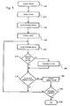
- Fig. 6 is a flow chart showing a method for imaging an anatomical structure on the virtual reality display of Fig. 4 , in accordance with a disclosed embodiment of the invention.
- Software programming code which embodies aspects of the present invention, is typically maintained in permanent storage, such as a computer readable medium.
- software programming code may be stored on a client or a server.
- the software programming code may be embodied on any of a variety of known media for use with a data processing system, such as a diskette, or hard drive, or CD-ROM.
- the code may be distributed on such media, or may be distributed to users from the memory or storage of one computer system over a network of some type to other computer systems for use by users of such other systems.
- Fig. 1 is a pictorial illustration of a system 20 that tracks and operates a medical instrument within a living body using a virtual touch screen, which is constructed and operative in accordance with a disclosed embodiment of the invention.
- An operator for example a physician 22 may use system 20 to obtain medical images using a probe, such as a catheter 23, which may be inserted into an internal body cavity, such as a chamber of a heart 24 of a subject 26.
- catheter 23 is used for diagnostic or therapeutic medical procedures, such as mapping electrical potentials in the heart or performing ablation of heart tissue.
- the catheter or other intra-body device may alternatively be used for other purposes, by itself or in conjunction with other treatment devices.
- the cardiac application described with respect to Fig. 1 is exemplary. The principles of the invention are applicable to many invasive medical and surgical procedures throughout the body.
- Fig. 2 is a pictorial illustration of catheter 23, in accordance with an embodiment of the present invention.
- the catheter shown is exemplary; many other types of catheters may be used as catheter 23.
- Catheter 23 typically comprises positioning controls 27 on a handle 28 to enable the physician to steer, locate and orient, and operate a distal end 29 of catheter 23 as desired.
- a pointing device e.g., joystick 52 is attached to handle 28.
- handle 28 comprises one or more touch-activated switches, shown as buttons 56.
- buttons 56 may be located on joystick 52.
- Joystick 52 and buttons 56 are used for controlling system 20, as described in detail herein below.
- Distal end 29 and joystick 52 include position sensors 32 and 54 respectively, each comprising sensor coils 35 as described herein below.
- distal end 29 comprises an ultrasonic imaging sensor 39.
- Ultrasonic imaging sensor 39 typically transmits a short burst of ultrasound energy and converts the reflected ultrasound into electrical signals, which are transmitted via cables 33 to console 34 ( Fig. 1 ), as is known in the art.
- distal end 29 also comprises at least one electrode 42 for performing diagnostic functions, therapeutic functions, or both, such as electro-physiological mapping and radiofrequency (RF) ablation.
- electrode 42 is used for sensing local electrical potentials. The electrical potentials measured by electrode 42 may be used in mapping the local electrical activity on the endocardial surface.
- the electrode measures the local electrical potential at that point. The measured potentials are converted into electrical signals and sent through catheter 23 to an image processor 43 ( Fig. 1 ), which converts the signals into an electro-anatomical map.
- electrode 42 may be used to measure parameters different from the electrical potentials described above, such as various tissue characteristics, temperature, and blood flow.
- system 20 comprises a positioning subsystem 30 that measures location and orientation coordinates of distal end 29 of catheter 23.
- location refers to the spatial coordinates of an object
- orientation refers to angular coordinates of the object
- position refers to the full positional information of the object, comprising both location and orientation coordinates.
- positioning subsystem 30 comprises a magnetic position tracking system that determines the position of distal end 29 of catheter 23.
- Positioning subsystem 30 typically comprises a set of external radiators, such as field generating elements, e.g., coils 31, which are in fixed, known locations external to the subject. Coils 31 generate fields, typically magnetic fields, in the vicinity of heart 24.
- position sensor 32 senses the fields generated by coils 31 and transmits, in response to the sensed fields, position-related electrical signals over cables 33 running through catheter 23 to console 34 ( Fig. 1 ). Alternatively, position sensor 32 may transmit signals to the console over a wireless link.
- position sensor 32 comprises at least two, and preferably three, sensor coils 35, adapted to the frequency of one of coils 31 as is known in the art.
- Sensor coils 35 are wound on either air cores or cores of material.
- the axes of sensor coils 35 should be non-parallel and preferably mutually orthogonal.
- Position sensor 54 which is located in the joystick 52, preferably in the handle, is similar to position sensor 32. Position sensor 54 senses the fields generated by coils 31, and is used to determine the position of the handle of joystick 52 including its angular orientation in space. Position sensor 54 requires at least one sensing coil, and preferably has three coils.
- console 34 comprises a position processor 36 that calculates the location and orientation of distal end 29 of catheter 23 based on the signals sent by position sensor 32 ( Fig. 2 ).
- Position processor 36 typically receives, amplifies, filters, digitizes, and otherwise processes signals from catheter 23.
- System 20 and position processor 36 may also be realized as elements of the CARTO XP EP Navigation and Ablation System, available from Biosense Webster, Inc., 3333 Diamond Canyon Road, Diamond Bar, CA 91765, and suitably modified to execute the principles of the present invention.
- image processor 43 uses the electrical signals received from ultrasonic imaging sensor 39 ( Fig. 2 ) and positional information received from position sensor 32 in distal end 29 of catheter 23 to produce an image of a target structure of the subject's heart.
- the images may be enhanced using electrical information derived from electrode 42.
- image processor 43 may not produce a medical image, but may merely produce an image of distal end 29 of catheter 23 overlaid on a representation of subject 26, or may simply show the position of distal end 29 with respect to a target within the subject, in order to assist physician 22 with a medical procedure.
- Images produced by image processor 43 are output on a display device 44.
- Fig. 1 shows an image 46 of part of heart 24.
- System 20 typically provides display controls, for example a GUI (Graphical User Interface), comprising windows, icons and menus, for manipulating and viewing images produced by image processor 43.
- GUI Graphic User Interface
- An interface device is used to move a cursor 48 on display device 44.
- the interface device comprises joystick 52 ( Fig. 2 ), which is within reach of physician 22 when he is using operating controls 27.
- rotation of the joystick may continuously control a parameter such as the edge threshold in an edge detection algorithm.
- Other joystick motions and button commands may be user-assigned in order to control other aspects of the operation of the system 20.
- physician 22 moves joystick 52
- the location of position sensor 54 is tracked by the position processor 36 ( Fig. 1 ) transmitted to console 34, where it is registered on the display 44.
- the position processor 36 translates joystick movements into movements of cursor 48 on display device 44.
- Fig. 3 is a diagram of an exemplary interface device 60 for use with system 20 ( Fig. 1 ), in accordance with an alternate embodiment of the invention.
- Interface device 60 may be a wand or stylus, and is shaped to be easily graspable and manipulable by physician 22 ( Fig. 1 ).
- Interface device 60 comprises position sensor 54 and buttons 56, as described above.
- Position sensor 54 senses magnetic fields produced by coils 31 ( Fig. 1 ) and transmits, in response to the sensed fields, position-related electrical signals over cables 63 to console 34.
- position sensor 54 may transmit signals to the console over a wireless link. In this way, system 20 is able to determine the position of interface device 60.
- a 3-dimensional spatial region 61 including screen 62 of display 40 is mapped by the position processor 36 to a spatial region 67 near or including device 60.
- a displacement of device 60 in the region 67 that changes its XY coordinates in coordinate system 65 produces a corresponding movement of a cursor on the screen 62.
- the device 60 is displaced so as to change its Z-coordinate and intersect virtual plane 70, physical contact with the screen 62 is emulated. This event stimulates the graphical user interface of the display 40 as though a physical touch screen were contacted at a point corresponding to the XY coordinate of the intersection in the plane 70.
- Icons and menus (not shown) on the display 40 are actuated by superimposing the cursor on them.
- the icons and menus are actuated by passing the cursor over them while pressing one of buttons 56. This causes an electrical signal to be transmitted along cables 33 to console 34, where the processor interprets the signal to activate the icon or menu.
- the tracking of a pointing device for a GUI is well known in the art, and is not described further here.
- physician 22 may move cursor 48 from a first position to a second position, in order to draw a corresponding line via the GUI from the first position to the second position, mark points using buttons 56, and otherwise interact with images and maps that are displayed on the display device.
- the images are displayed on a virtual reality display rather than a conventional display monitor.
- Fig. 4 is a pictorial illustration of a device that produces a virtual reality display, in accordance with an alternate embodiment of the invention.
- Virtual reality goggles 100 comprise at least one, and typically two, display devices 105, supported by a frame 110, constructed so that physician 22 ( Fig. 1 ) may wear goggles 100 with display devices 105 in front of his eyes.
- Display devices 105 show virtual images, ages, for example, of a part of heart 24 ( Fig. 1 ) and distal end 29 of catheter 23 ( Fig. 2 ), as described herein below.
- display devices 105 may be transparent, or partially transparent, in order to provide augmented reality images in which the virtual images are superimposed on the body of subject 26 ( Fig. 1 ).
- Goggles 100 comprise a position sensor 132, similar to position sensor 32, which senses magnetic fields produced by coils 31 ( Fig. 1 ) and transmits, in response to the sensed fields, position-related electrical signals to console 34 ( Fig. 1 ), using a wireless transmitter 140.
- Wireless transmitter 140 may also be used as a receiver for images to be displayed on display devices 105. Alternatively, the transmitter may be wired to the console.
- Position sensor 132 is similar to position sensor 32, but may comprise a miniaturized position sensor, for example as described in U.S Patent No. 6,201,387, issued to Govari .
- position sensor 132 may comprise a wireless position sensor.
- a suitable device is described in U.S. Patent Application Publication No. 2005/0099290 .
- wireless transmitter 140 acts solely as a receiver for images from image processor 43 ( Fig. 1 ).
- position sensor 132 may transmit signals to the console over a cable (not shown). However, this alternative is less convenient. Similarly, images to be displayed on display devices 105 may be received over cables (not shown). Because the positions of display devices 105 are fixed in relation to position sensor 132, system 20 is able to determine the positions of each of display devices 105. Using the information provided by the position sensor 132, the position processor 36 ( Fig. 1 ) can register the virtual reality display with the body of the patient. In this manner, the operator can view an image of an organ superimposed on an image of the patient's body in the proper position and orientation, and can use the device 60 ( Fig. 3 ) to interact with the images as described above.
- each of display devices 105 may be attached to its own position sensor 132. This allows greater flexibility of movement of the goggles, since the relative positions of display devices 105 need not be constant.
- Fig. 4 shows each position sensor 132 connected to a separate wireless transmitter 140, a single wireless transmitter 140 may be used.
- the virtual reality image may be manipulated using many combinations of interface devices such as joystick 52 or interface device 60, as described above.
- interface devices such as joystick 52 or interface device 60, as described above.
- some embodiments may become less convenient than others. For example, some phases may be hazardous, e.g., taking place under conditions of radiation exposure, and requiring hands-off actuation of the medical instrument on the part of the physician 22. In such cases the use of goggles 100 may be preferable. In other situations, the lighting conditions in the operatory may be unsuitable for use of goggles 100.
- position sensors 32, 54, 132 may be replaced by radiators, e.g., coils, that generate magnetic fields, which are received by sensors outside the subject's body.
- the external sensors generate the position-related electrical signals.
- FIG. 5 is a flow chart showing a method for performing invasive medical operations with the assistance of a virtual touch screen, in accordance with a disclosed embodiment of the invention.
- the method begins at an initial step 150, where the position of distal end 29 ( Fig. 1 ) of catheter 23 is determined, typically using the magnetic fields produced by coils 31 and sensed by position sensor 32 ( Fig. 2 ).
- the position of distal end 29 may be determined by external position sensors that detect magnetic fields generated at a fixed position relative to distal end 29.
- an image for example image 46
- the image may be an image of subject 26, which may be obtained, for example, using catheter 23.
- the image may be an image of distal end 29 overlaid on a representation of subject 26. Further alternatively, the image may show the position of distal end 29 with respect to a target within the subject. Steps 150 and 152 may be repeated as distal end 29 moves.
- the position of the interface device is determined, for example by position sensor 54 ( Fig. 2 ).
- position sensors 32, 54 may be replaced by a radiator, which is used to as a reference establish coordinates for the system.
- the same external sensors are used to detect the positions of the distal end of the catheter and the interface device.
- cursor 48 is positioned on display 44.
- the initial position may be predefined or random.
- step 165 typically performed after a time delay, or after an interrupt, the position of the interface device is determined, as in step 155.
- step 170 it is determined whether the interface device has moved since the previous iteration of step 165, or step 155 if this is the first iteration. If the determination at determination step 170 is negative, then control proceeds to a decision step 175, described below.
- step 170 determines whether the determination at decision step 170 is affirmative. If the determination at decision step 170 is affirmative, then control proceeds to step 180. Cursor 48 is repositioned on display 44 in response to the displacement of the interface device relative to its previous position. Control proceeds to decision step 175.
- display controls for example a GUI as described above, appear on display 44.
- decision step 175 it is determined whether the cursor is superimposed on one of the display controls. If the determination at decision step 175 is negative, then control returns to step 165.
- step 185 control proceeds to step 185.
- the display control is actuated. This may cause a change in the orientation or scale of the image on display 44, or other changes to the display of the image or may actuate a function of catheter 23, according to a computer application that is controlled via the GUI.
- decision step 190 it is determined whether the procedure is complete. Typically, this is indicated by the actuation of an appropriate display control at step 185. If the determination at decision step 190 is negative, then control returns to step 165.
- control proceeds to final step 195, where the method ends.
- Fig. 6 is a flow chart showing a method for imaging an anatomical structure on the virtual reality display of Fig. 4 , in accordance with a disclosed embodiment of the invention.
- the process steps are shown in a particular linear sequence in Fig. 6 for clarity of presentation. However, it will be evident that many of them can be performed in parallel, asynchronously, or in different orders. For example, acquiring the image and locating the display devices may be performed in either order, or simultaneously.
- the method begins at initial step 205, where an image, typically three-dimensional, of a part of an anatomical structure is acquired.
- an image typically three-dimensional, of a part of an anatomical structure is acquired.
- this may be performed as described for example, in U.S. Patent Application Publication No. 2006/0241445 .
- one or more position sensors 132 determine the positions of display devices 105.
- the position information is transmitted to console 34.
- image processor 43 uses position information from step 220 and standard geometrical techniques to obtain, for each of display devices 105, a 2-dimensional projection of the image.
- the projections are transmitted to display devices 105 ( Fig. 4 ) and displayed.
Claims (8)
- Gerät für invasive medizinische Operationen im Körper eines Lebewesens, umfassend:ein oder mehr Feldgeneratorelemente (31), die an bekannten Stellen zur Erzeugung von Magnetfeldern mit jeweiligen Frequenzen angeordnet sind;ein medizinisches Instrument (23) zur Einführung in den Körper, das einen ersten damit verbundenen magnetischen Positionssensor (32) aufweist, der erste Signale als Reaktion auf die Magnetfelder aussendet;einen Joystick (52) mit einem zweiten damit verbundenen magnetischen Positionssensor (54), der zweite Signale als Reaktion auf die Magnetfelder aussendet;einen Positionsprozessor (36) zum Empfang der ersten Signale und der zweiten Signale und zur Bestimmung der jeweiligen Positionen de Joysticks und des medizinischen Instruments bezüglich der bekannten Stellen als Reaktion auf die ersten Signale und die zweiten Signale;eine Anzeigevorrichtung (44; 105) zum Anzeigen eines Bildes als Reaktion auf die Position des medizinischen Instruments, wobei die Anzeigevorrichtung einen darauf bewegbaren Cursor (8) unter Kontrolle des Positionsprozessors als Reaktion auf Veränderungen der Position des Joysticks aufweist; undPositionierungskontrollen für das medizinische Instrument auf einem Griff (28) des medizinischen Instruments (23) und worin der Joystick (52) am Griff befestigt ist.
- Gerät nach Anspruch 1, worin die Anzeigevorrichtung (105) eine virtuelle Anzeigevorrichtung mit einem dritten magnetischen Positionssensor (132) umfasst, der dritte Signale als Reaktion auf die Magnetfelder aussendet.
- Gerät nach Anspruch 1, worin der erste magnetische Positionssensor (32) und der zweite magnetische Positionssensor (54) zumindest zwei Sensorspulen (35) umfassen.
- Gerät für invasive medizinische Operationen im Körper eines Lebewesens, umfassend:ein medizinisches Instrument (23) zur Einführung in eine anatomische Struktur in dem Körper, das ein oder mehr erste Felderzeugungselemente zur Erzeugung von ersten Magnetfeldern bei jeweiligen Frequenzen aufweist;einen Joystick (52) mit ein oder mehr zweiten Felderzeugungselementen zur Erzeugung von zweiten Magnetfeldern bei jeweiligen Frequenzen;einen magnetischen Positionssensor an einer bekannten Stelle, der erste Signale als Reaktion auf die ersten Magnetfelder aussendet und der zweite Signale als Reaktion auf die zweiten Magnetfelder aussendet;einen Positionsprozessor (36) zum Empfang der ersten Signale und der zweiten Signale und zur Bestimmung der jeweiligen Positionen des Joysticks und des medizinischen Instruments bezüglich der bekannten Stelle als Reaktion auf die ersten Signale und die zweiten Signale;eine Anzeigevorrichtung (44; 105) zum Anzeigen eines Bildes als Reaktion auf die Position des medizinischen Instruments, wobei die Anzeigevorrichtung einen darauf bewegbaren Cursor (48) unter Kontrolle des Positionsprozessors aufweist, wobei Bewegungen des Cursors von dem Positionsprozessor als Reaktion auf Veränderungen der Position des Joysticks kontrolliert werden; undPositionierungskontrollen für das medizinische Instrument auf einem Griff (28) des medizinischen Instruments (23) und worin der Joystick (52) am Griff befestigt ist.
- Gerät nach Anspruch 4, worin die Anzeigevorrichtung (105) eine virtuelle Anzeigevorrichtung mit ein oder mehr dritten Felderzeugungselementen zur Erzeugung von dritten Magnetfeldern umfasst, wobei der magnetische Positionssensor auf die dritten Magnetfelder reagiert.
- Gerät nach Anspruch 4, worin die Anzeigevorrichtung (44; 105) eine Linie von einer ersten Position zu einer zweiten Position auf der Anzeigevorrichtung ziehen kann, wenn der Cursor (48) von der ersten Position in die zweite Position bewegt wird.
- Gerät nach Anspruch 4, worin der magnetische Positionssensor zumindest zwei Sensorspulen (31) umfasst.
- Gerät nach Anspruch 1 oder 4, worin die Anzeigevorrichtung (44; 105) eine Anzeigekontrolle aufweist, die als Reaktion auf eine Überlagerung des Cursors darauf betätigt wird.
Applications Claiming Priority (1)
| Application Number | Priority Date | Filing Date | Title |
|---|---|---|---|
| US12/039,779 US8926511B2 (en) | 2008-02-29 | 2008-02-29 | Location system with virtual touch screen |
Publications (2)
| Publication Number | Publication Date |
|---|---|
| EP2096523A1 EP2096523A1 (de) | 2009-09-02 |
| EP2096523B1 true EP2096523B1 (de) | 2013-07-10 |
Family
ID=40672316
Family Applications (1)
| Application Number | Title | Priority Date | Filing Date |
|---|---|---|---|
| EP09250552.8A Active EP2096523B1 (de) | 2008-02-29 | 2009-02-27 | Lokalisierungssystem mit virtuellem Berührungsbildschirm |
Country Status (10)
| Country | Link |
|---|---|
| US (1) | US8926511B2 (de) |
| EP (1) | EP2096523B1 (de) |
| JP (1) | JP5436886B2 (de) |
| KR (1) | KR101612278B1 (de) |
| CN (2) | CN104605855B (de) |
| AU (1) | AU2009200770B2 (de) |
| BR (1) | BRPI0901476B8 (de) |
| CA (1) | CA2656309C (de) |
| IL (1) | IL197318A (de) |
| MX (1) | MX350265B (de) |
Cited By (1)
| Publication number | Priority date | Publication date | Assignee | Title |
|---|---|---|---|---|
| US8611984B2 (en) | 2009-04-08 | 2013-12-17 | Covidien Lp | Locatable catheter |
Families Citing this family (91)
| Publication number | Priority date | Publication date | Assignee | Title |
|---|---|---|---|---|
| ATE438335T1 (de) | 2003-09-15 | 2009-08-15 | Super Dimension Ltd | System aus zubehör zur verwendung mit bronchoskopen |
| EP2316328B1 (de) | 2003-09-15 | 2012-05-09 | Super Dimension Ltd. | Umhüllungsvorrichtung zur Fixierung von Bronchoskopen |
| US8764725B2 (en) | 2004-02-09 | 2014-07-01 | Covidien Lp | Directional anchoring mechanism, method and applications thereof |
| US20090264966A1 (en) * | 2004-11-02 | 2009-10-22 | Pixeloptics, Inc. | Device for Inductive Charging of Implanted Electronic Devices |
| US9801709B2 (en) | 2004-11-02 | 2017-10-31 | E-Vision Smart Optics, Inc. | Electro-active intraocular lenses |
| US8778022B2 (en) | 2004-11-02 | 2014-07-15 | E-Vision Smart Optics Inc. | Electro-active intraocular lenses |
| US8905920B2 (en) | 2007-09-27 | 2014-12-09 | Covidien Lp | Bronchoscope adapter and method |
| US9161817B2 (en) | 2008-03-27 | 2015-10-20 | St. Jude Medical, Atrial Fibrillation Division, Inc. | Robotic catheter system |
| US8343096B2 (en) | 2008-03-27 | 2013-01-01 | St. Jude Medical, Atrial Fibrillation Division, Inc. | Robotic catheter system |
| US8317744B2 (en) | 2008-03-27 | 2012-11-27 | St. Jude Medical, Atrial Fibrillation Division, Inc. | Robotic catheter manipulator assembly |
| US9241768B2 (en) | 2008-03-27 | 2016-01-26 | St. Jude Medical, Atrial Fibrillation Division, Inc. | Intelligent input device controller for a robotic catheter system |
| US8641664B2 (en) | 2008-03-27 | 2014-02-04 | St. Jude Medical, Atrial Fibrillation Division, Inc. | Robotic catheter system with dynamic response |
| US8684962B2 (en) | 2008-03-27 | 2014-04-01 | St. Jude Medical, Atrial Fibrillation Division, Inc. | Robotic catheter device cartridge |
| US8641663B2 (en) | 2008-03-27 | 2014-02-04 | St. Jude Medical, Atrial Fibrillation Division, Inc. | Robotic catheter system input device |
| US9575140B2 (en) | 2008-04-03 | 2017-02-21 | Covidien Lp | Magnetic interference detection system and method |
| US8473032B2 (en) | 2008-06-03 | 2013-06-25 | Superdimension, Ltd. | Feature-based registration method |
| US8218847B2 (en) | 2008-06-06 | 2012-07-10 | Superdimension, Ltd. | Hybrid registration method |
| US8932207B2 (en) | 2008-07-10 | 2015-01-13 | Covidien Lp | Integrated multi-functional endoscopic tool |
| US8200466B2 (en) | 2008-07-21 | 2012-06-12 | The Board Of Trustees Of The Leland Stanford Junior University | Method for tuning patient-specific cardiovascular simulations |
| US9405886B2 (en) | 2009-03-17 | 2016-08-02 | The Board Of Trustees Of The Leland Stanford Junior University | Method for determining cardiovascular information |
| US9330497B2 (en) | 2011-08-12 | 2016-05-03 | St. Jude Medical, Atrial Fibrillation Division, Inc. | User interface devices for electrophysiology lab diagnostic and therapeutic equipment |
| US9439736B2 (en) | 2009-07-22 | 2016-09-13 | St. Jude Medical, Atrial Fibrillation Division, Inc. | System and method for controlling a remote medical device guidance system in three-dimensions using gestures |
| WO2011123669A1 (en) | 2010-03-31 | 2011-10-06 | St. Jude Medical, Atrial Fibrillation Division, Inc. | Intuitive user interface control for remote catheter navigation and 3d mapping and visualization systems |
| KR101113219B1 (ko) * | 2009-12-08 | 2012-02-20 | 삼성메디슨 주식회사 | 증강현실 초음파 시스템 및 증강현실 초음파 영상 형성 방법 |
| US20120194553A1 (en) * | 2010-02-28 | 2012-08-02 | Osterhout Group, Inc. | Ar glasses with sensor and user action based control of external devices with feedback |
| AU2011220382A1 (en) | 2010-02-28 | 2012-10-18 | Microsoft Corporation | Local advertising content on an interactive head-mounted eyepiece |
| US20120249797A1 (en) | 2010-02-28 | 2012-10-04 | Osterhout Group, Inc. | Head-worn adaptive display |
| US10180572B2 (en) | 2010-02-28 | 2019-01-15 | Microsoft Technology Licensing, Llc | AR glasses with event and user action control of external applications |
| US20150309316A1 (en) | 2011-04-06 | 2015-10-29 | Microsoft Technology Licensing, Llc | Ar glasses with predictive control of external device based on event input |
| US20110218550A1 (en) * | 2010-03-08 | 2011-09-08 | Tyco Healthcare Group Lp | System and method for determining and adjusting positioning and orientation of a surgical device |
| US9216257B2 (en) * | 2010-03-25 | 2015-12-22 | Medtronic, Inc. | Method and apparatus for guiding an external needle to an implantable device |
| US8483802B2 (en) | 2010-03-25 | 2013-07-09 | Medtronic, Inc. | Method and apparatus for guiding an external needle to an implantable device |
| US9339601B2 (en) * | 2010-03-25 | 2016-05-17 | Medtronic, Inc. | Method and apparatus for guiding an external needle to an implantable device |
| US8475407B2 (en) * | 2010-03-25 | 2013-07-02 | Medtronic, Inc. | Method and apparatus for guiding an external needle to an implantable device |
| US10582834B2 (en) | 2010-06-15 | 2020-03-10 | Covidien Lp | Locatable expandable working channel and method |
| DE102010027526B4 (de) * | 2010-07-16 | 2012-04-19 | Gottfried Wilhelm Leibniz Universität Hannover | Handführbares Vermessungs- und Projektionssystem und Verfahren |
| US8315812B2 (en) | 2010-08-12 | 2012-11-20 | Heartflow, Inc. | Method and system for patient-specific modeling of blood flow |
| TWI501130B (zh) * | 2010-10-18 | 2015-09-21 | Ind Tech Res Inst | 虛擬觸控輸入系統 |
| CN102920509A (zh) * | 2012-10-30 | 2013-02-13 | 华南理工大学 | 一种基于超声波的实时无线手术导航装置 |
| US20140171785A1 (en) * | 2012-12-17 | 2014-06-19 | Biosense Webster (Israel), Ltd. | Recognizing which instrument is currently active |
| BR112016003663B1 (pt) * | 2013-08-23 | 2022-05-10 | Ethicon Endo-Surgery, Llc | Sistema em comunicação de sinal com um instrumento cirúrgico para exibir retroinformações durante uma operação endoscópica, dispositivo em comunicação de sinal com um instrumento endoscópico e sistema para uso com um instrumento cirúrgico |
| US11103174B2 (en) | 2013-11-13 | 2021-08-31 | Biosense Webster (Israel) Ltd. | Reverse ECG mapping |
| US9629570B2 (en) | 2013-11-21 | 2017-04-25 | Biosense Webster (Israel) Ltd. | Tracking of catheter from insertion point to heart using impedance measurements |
| CN103989520A (zh) * | 2014-04-30 | 2014-08-20 | 西安云合生物科技有限公司 | 一种触摸式多功能电刀 |
| US10952593B2 (en) | 2014-06-10 | 2021-03-23 | Covidien Lp | Bronchoscope adapter |
| JP6429618B2 (ja) * | 2014-12-22 | 2018-11-28 | オリンパス株式会社 | 内視鏡挿入形状観測装置 |
| US10181219B1 (en) * | 2015-01-21 | 2019-01-15 | Google Llc | Phone control and presence in virtual reality |
| JP7136558B2 (ja) | 2015-03-05 | 2022-09-13 | マジック リープ, インコーポレイテッド | 拡張現実のためのシステムおよび方法 |
| US10180734B2 (en) | 2015-03-05 | 2019-01-15 | Magic Leap, Inc. | Systems and methods for augmented reality |
| US10838207B2 (en) | 2015-03-05 | 2020-11-17 | Magic Leap, Inc. | Systems and methods for augmented reality |
| US10426555B2 (en) | 2015-06-03 | 2019-10-01 | Covidien Lp | Medical instrument with sensor for use in a system and method for electromagnetic navigation |
| KR101647467B1 (ko) * | 2015-06-05 | 2016-08-11 | 주식회사 메드릭스 | 증강현실을 이용한 외과 수술용 3d 안경 시스템 |
| US9947091B2 (en) * | 2015-11-16 | 2018-04-17 | Biosense Webster (Israel) Ltd. | Locally applied transparency for a CT image |
| WO2017096396A1 (en) | 2015-12-04 | 2017-06-08 | Magic Leap, Inc. | Relocalization systems and methods |
| CN105395252A (zh) * | 2015-12-10 | 2016-03-16 | 哈尔滨工业大学 | 具有人机交互的可穿戴式血管介入手术三维立体图像导航装置 |
| WO2017104263A1 (ja) * | 2015-12-17 | 2017-06-22 | オリンパス株式会社 | 超音波観測装置、処理装置、超音波観測装置の作動方法および超音波観測装置の作動プログラム |
| KR20180110051A (ko) * | 2016-02-05 | 2018-10-08 | 매직 립, 인코포레이티드 | 증강 현실을 위한 시스템들 및 방법들 |
| EP3429463A4 (de) * | 2016-03-17 | 2019-11-27 | Becton, Dickinson and Company | Patientenaktensystem unter verwendung eines patientenavatars |
| CN105788390A (zh) * | 2016-04-29 | 2016-07-20 | 吉林医药学院 | 基于增强现实的医学解剖辅助教学系统 |
| US10478254B2 (en) | 2016-05-16 | 2019-11-19 | Covidien Lp | System and method to access lung tissue |
| US20170354338A1 (en) * | 2016-06-09 | 2017-12-14 | Biosense Webster (Israel) Ltd. | Dual-function sensors for a basket catheter |
| US10649211B2 (en) | 2016-08-02 | 2020-05-12 | Magic Leap, Inc. | Fixed-distance virtual and augmented reality systems and methods |
| CN106251752A (zh) * | 2016-10-25 | 2016-12-21 | 深圳市科创数字显示技术有限公司 | Ar和vr相结合的医学培训系统 |
| US10792106B2 (en) | 2016-10-28 | 2020-10-06 | Covidien Lp | System for calibrating an electromagnetic navigation system |
| US10615500B2 (en) | 2016-10-28 | 2020-04-07 | Covidien Lp | System and method for designing electromagnetic navigation antenna assemblies |
| US10446931B2 (en) | 2016-10-28 | 2019-10-15 | Covidien Lp | Electromagnetic navigation antenna assembly and electromagnetic navigation system including the same |
| US10751126B2 (en) | 2016-10-28 | 2020-08-25 | Covidien Lp | System and method for generating a map for electromagnetic navigation |
| US10722311B2 (en) | 2016-10-28 | 2020-07-28 | Covidien Lp | System and method for identifying a location and/or an orientation of an electromagnetic sensor based on a map |
| US10517505B2 (en) | 2016-10-28 | 2019-12-31 | Covidien Lp | Systems, methods, and computer-readable media for optimizing an electromagnetic navigation system |
| US10638952B2 (en) | 2016-10-28 | 2020-05-05 | Covidien Lp | Methods, systems, and computer-readable media for calibrating an electromagnetic navigation system |
| US10418705B2 (en) | 2016-10-28 | 2019-09-17 | Covidien Lp | Electromagnetic navigation antenna assembly and electromagnetic navigation system including the same |
| KR101908016B1 (ko) | 2016-12-08 | 2018-12-11 | 제주대학교 산학협력단 | 현실과 사이버 세상을 연계한 IoT 기반 O2O 도망자 추적 게임 시스템 및 방법 |
| US10918445B2 (en) * | 2016-12-19 | 2021-02-16 | Ethicon Llc | Surgical system with augmented reality display |
| US10812936B2 (en) | 2017-01-23 | 2020-10-20 | Magic Leap, Inc. | Localization determination for mixed reality systems |
| AU2018236457B2 (en) | 2017-03-17 | 2021-04-29 | Magic Leap, Inc. | Mixed reality system with virtual content warping and method of generating virtual content using same |
| IL303275B1 (en) | 2017-03-17 | 2024-04-01 | Magic Leap Inc | A mixed reality system with the assembly of multi-source virtual content and a method for creating virtual content using it |
| KR102594063B1 (ko) | 2017-03-17 | 2023-10-24 | 매직 립, 인코포레이티드 | 컬러 가상 콘텐츠 워핑을 갖는 혼합 현실 시스템 및 이를 사용하여 가상 콘텐츠를 생성하는 방법 |
| US10478255B2 (en) * | 2017-04-20 | 2019-11-19 | The Cleveland Clinic Foundation | System and method for holographic image-guided percutaneous endovascular percutaneous procedures |
| US10390891B2 (en) * | 2017-06-13 | 2019-08-27 | Biosense Webster (Israel) Ltd. | Hologram lens for positioning an orthopedic implant |
| USD882633S1 (en) | 2017-07-06 | 2020-04-28 | Biosense Webster (Israel) Ltd. | Display screen or portion thereof with icon |
| US11219489B2 (en) | 2017-10-31 | 2022-01-11 | Covidien Lp | Devices and systems for providing sensors in parallel with medical tools |
| US11071595B2 (en) | 2017-12-14 | 2021-07-27 | Verb Surgical Inc. | Multi-panel graphical user interface for a robotic surgical system |
| KR102477325B1 (ko) * | 2017-12-14 | 2022-12-16 | 버브 서지컬 인크. | 로봇 수술 시스템용 다중 패널 그래픽 사용자 인터페이스 |
| WO2020023523A1 (en) | 2018-07-23 | 2020-01-30 | Magic Leap, Inc. | Intra-field sub code timing in field sequential displays |
| CN112513712B (zh) | 2018-07-23 | 2023-05-09 | 奇跃公司 | 具有虚拟内容翘曲的混合现实系统和使用该系统生成虚拟内容的方法 |
| EP3840645A4 (de) * | 2018-08-22 | 2021-10-20 | Magic Leap, Inc. | Patientensichtsystem |
| CN109036046A (zh) * | 2018-09-05 | 2018-12-18 | 南京阿波罗机器人科技有限公司 | 一种stem触屏可编程电子积木控制器 |
| US10832392B2 (en) * | 2018-12-19 | 2020-11-10 | Siemens Healthcare Gmbh | Method, learning apparatus, and medical imaging apparatus for registration of images |
| US11723517B2 (en) * | 2019-12-31 | 2023-08-15 | Biosense Webster (Israel) Ltd. | Wiring of trocar having movable camera and fixed position sensor |
| CN113180574A (zh) * | 2021-04-06 | 2021-07-30 | 重庆博仕康科技有限公司 | 内窥镜的快插结构及内窥镜 |
| CN113610853B (zh) * | 2021-10-11 | 2022-01-28 | 北京工业大学 | 基于静息态脑功能图像的情绪状态展示方法、装置及系统 |
Family Cites Families (34)
| Publication number | Priority date | Publication date | Assignee | Title |
|---|---|---|---|---|
| US5417210A (en) * | 1992-05-27 | 1995-05-23 | International Business Machines Corporation | System and method for augmentation of endoscopic surgery |
| WO1994004938A1 (en) * | 1992-08-14 | 1994-03-03 | British Telecommunications Public Limited Company | Position location system |
| US6690963B2 (en) * | 1995-01-24 | 2004-02-10 | Biosense, Inc. | System for determining the location and orientation of an invasive medical instrument |
| US5729129A (en) * | 1995-06-07 | 1998-03-17 | Biosense, Inc. | Magnetic location system with feedback adjustment of magnetic field generator |
| US6702736B2 (en) * | 1995-07-24 | 2004-03-09 | David T. Chen | Anatomical visualization system |
| AU709081B2 (en) * | 1996-02-15 | 1999-08-19 | Biosense, Inc. | Medical procedures and apparatus using intrabody probes |
| IL125761A (en) * | 1996-02-15 | 2005-05-17 | Biosense Inc | Independently positionable transducers for location system |
| US6129668A (en) * | 1997-05-08 | 2000-10-10 | Lucent Medical Systems, Inc. | System and method to determine the location and orientation of an indwelling medical device |
| US6201387B1 (en) * | 1997-10-07 | 2001-03-13 | Biosense, Inc. | Miniaturized position sensor having photolithographic coils for tracking a medical probe |
| US7174201B2 (en) * | 1999-03-11 | 2007-02-06 | Biosense, Inc. | Position sensing system with integral location pad and position display |
| US7343195B2 (en) * | 1999-05-18 | 2008-03-11 | Mediguide Ltd. | Method and apparatus for real time quantitative three-dimensional image reconstruction of a moving organ and intra-body navigation |
| US6233476B1 (en) * | 1999-05-18 | 2001-05-15 | Mediguide Ltd. | Medical positioning system |
| US9572519B2 (en) | 1999-05-18 | 2017-02-21 | Mediguide Ltd. | Method and apparatus for invasive device tracking using organ timing signal generated from MPS sensors |
| US7386339B2 (en) * | 1999-05-18 | 2008-06-10 | Mediguide Ltd. | Medical imaging and navigation system |
| US6427079B1 (en) * | 1999-08-09 | 2002-07-30 | Cormedica Corporation | Position and orientation measuring with magnetic fields |
| JP3520062B2 (ja) | 2001-08-10 | 2004-04-19 | 日清食品株式会社 | 酸味低減された生タイプ即席麺及びその製造方法 |
| US6695779B2 (en) | 2001-08-16 | 2004-02-24 | Siemens Corporate Research, Inc. | Method and apparatus for spatiotemporal freezing of ultrasound images in augmented reality visualization |
| US7324085B2 (en) * | 2002-01-25 | 2008-01-29 | Autodesk, Inc. | Techniques for pointing to locations within a volumetric display |
| US7285117B2 (en) * | 2002-03-15 | 2007-10-23 | Boston Scientific Scimed, Inc. | Medical device control systems |
| US7769427B2 (en) * | 2002-07-16 | 2010-08-03 | Magnetics, Inc. | Apparatus and method for catheter guidance control and imaging |
| US20040068178A1 (en) * | 2002-09-17 | 2004-04-08 | Assaf Govari | High-gradient recursive locating system |
| US7306593B2 (en) * | 2002-10-21 | 2007-12-11 | Biosense, Inc. | Prediction and assessment of ablation of cardiac tissue |
| CN1747679B (zh) * | 2003-02-04 | 2012-10-03 | 奥林巴斯株式会社 | 医疗装置引导系统及其控制方法 |
| US7347821B2 (en) * | 2003-06-26 | 2008-03-25 | Koninklijke Philips Electronics N.V. | Adaptive processing of contrast enhanced ultrasonic diagnostic images |
| US7280863B2 (en) * | 2003-10-20 | 2007-10-09 | Magnetecs, Inc. | System and method for radar-assisted catheter guidance and control |
| US7397364B2 (en) * | 2003-11-11 | 2008-07-08 | Biosense Webster, Inc. | Digital wireless position sensor |
| CN1901835A (zh) * | 2003-11-14 | 2007-01-24 | 通用电气公司 | 减少电磁跟踪器中失真的系统和方法 |
| US7983733B2 (en) * | 2004-10-26 | 2011-07-19 | Stereotaxis, Inc. | Surgical navigation using a three-dimensional user interface |
| EP1815424B1 (de) | 2004-11-16 | 2019-01-09 | Koninklijke Philips N.V. | Berührungslose manipulation von bildern für regionale verbesserung |
| US20060241445A1 (en) * | 2005-04-26 | 2006-10-26 | Altmann Andres C | Three-dimensional cardial imaging using ultrasound contour reconstruction |
| US20060281990A1 (en) * | 2005-05-06 | 2006-12-14 | Viswanathan Raju R | User interfaces and navigation methods for vascular navigation |
| CN101375173A (zh) * | 2006-01-30 | 2009-02-25 | 皇家飞利浦电子股份有限公司 | 用于介入乳房磁共振成像的自动系统 |
| JP4533863B2 (ja) | 2006-03-28 | 2010-09-01 | 本田技研工業株式会社 | ワーク位置決めテーブル及びこのワーク位置決めテーブルを備える工作機械 |
| US20090080738A1 (en) * | 2007-05-01 | 2009-03-26 | Dror Zur | Edge detection in ultrasound images |
-
2008
- 2008-02-29 US US12/039,779 patent/US8926511B2/en active Active
-
2009
- 2009-02-26 AU AU2009200770A patent/AU2009200770B2/en not_active Ceased
- 2009-02-26 IL IL197318A patent/IL197318A/en active IP Right Grant
- 2009-02-27 CN CN201510029456.5A patent/CN104605855B/zh active Active
- 2009-02-27 JP JP2009045364A patent/JP5436886B2/ja active Active
- 2009-02-27 KR KR1020090016871A patent/KR101612278B1/ko active IP Right Grant
- 2009-02-27 CN CN200910130767A patent/CN101530325A/zh active Pending
- 2009-02-27 CA CA2656309A patent/CA2656309C/en active Active
- 2009-02-27 EP EP09250552.8A patent/EP2096523B1/de active Active
- 2009-02-27 BR BRPI0901476A patent/BRPI0901476B8/pt not_active IP Right Cessation
- 2009-03-02 MX MX2009002363A patent/MX350265B/es active IP Right Grant
Cited By (1)
| Publication number | Priority date | Publication date | Assignee | Title |
|---|---|---|---|---|
| US8611984B2 (en) | 2009-04-08 | 2013-12-17 | Covidien Lp | Locatable catheter |
Also Published As
| Publication number | Publication date |
|---|---|
| AU2009200770B2 (en) | 2014-11-27 |
| CN101530325A (zh) | 2009-09-16 |
| KR101612278B1 (ko) | 2016-04-14 |
| MX2009002363A (es) | 2009-08-31 |
| JP2009207895A (ja) | 2009-09-17 |
| IL197318A (en) | 2015-06-30 |
| MX350265B (es) | 2017-08-31 |
| BRPI0901476B8 (pt) | 2021-06-22 |
| KR20090093877A (ko) | 2009-09-02 |
| JP5436886B2 (ja) | 2014-03-05 |
| CN104605855B (zh) | 2017-09-08 |
| US20090221907A1 (en) | 2009-09-03 |
| US8926511B2 (en) | 2015-01-06 |
| BRPI0901476A2 (pt) | 2010-01-26 |
| EP2096523A1 (de) | 2009-09-02 |
| CA2656309A1 (en) | 2009-08-29 |
| IL197318A0 (en) | 2009-12-24 |
| CN104605855A (zh) | 2015-05-13 |
| BRPI0901476B1 (pt) | 2019-11-26 |
| CA2656309C (en) | 2016-11-22 |
| AU2009200770A1 (en) | 2009-09-17 |
Similar Documents
| Publication | Publication Date | Title |
|---|---|---|
| EP2096523B1 (de) | Lokalisierungssystem mit virtuellem Berührungsbildschirm | |
| US20220346886A1 (en) | Systems and methods of pose estimation and calibration of perspective imaging system in image guided surgery | |
| US11013561B2 (en) | Medical device navigation system | |
| US10357322B2 (en) | System and method for controlling a remote medical device guidance system in three-dimensions using gestures | |
| US8213693B1 (en) | System and method to track and navigate a tool through an imaged subject | |
| US7466303B2 (en) | Device and process for manipulating real and virtual objects in three-dimensional space | |
| EP2769689B1 (de) | Computerimplementierte Technik zur Berechnung einer Position einer chirurgischen Vorrichtung | |
| US20060116576A1 (en) | System and use thereof to provide indication of proximity between catheter and location of interest in 3-D space | |
| US20080287783A1 (en) | System and method of tracking delivery of an imaging probe | |
| US20080287805A1 (en) | System and method to guide an instrument through an imaged subject | |
| US7940972B2 (en) | System and method of extended field of view image acquisition of an imaged subject | |
| US8948476B2 (en) | Determination of cardiac geometry responsive to doppler based imaging of blood flow characteristics | |
| EP4233762A2 (de) | Verfahren und system zur verfolgung und visualisierung von medizinischen vorrichtungen | |
| WO2012001550A1 (en) | Method and system for creating physician-centric coordinate system |
Legal Events
| Date | Code | Title | Description |
|---|---|---|---|
| PUAI | Public reference made under article 153(3) epc to a published international application that has entered the european phase |
Free format text: ORIGINAL CODE: 0009012 |
|
| AK | Designated contracting states |
Kind code of ref document: A1 Designated state(s): AT BE BG CH CY CZ DE DK EE ES FI FR GB GR HR HU IE IS IT LI LT LU LV MC MK MT NL NO PL PT RO SE SI SK TR |
|
| AX | Request for extension of the european patent |
Extension state: AL BA RS |
|
| 17P | Request for examination filed |
Effective date: 20100202 |
|
| 17Q | First examination report despatched |
Effective date: 20100225 |
|
| AKX | Designation fees paid |
Designated state(s): AT BE BG CH CY CZ DE DK EE ES FI FR GB GR HR HU IE IS IT LI LT LU LV MC MK MT NL NO PL PT RO SE SI SK TR |
|
| GRAP | Despatch of communication of intention to grant a patent |
Free format text: ORIGINAL CODE: EPIDOSNIGR1 |
|
| GRAS | Grant fee paid |
Free format text: ORIGINAL CODE: EPIDOSNIGR3 |
|
| GRAA | (expected) grant |
Free format text: ORIGINAL CODE: 0009210 |
|
| AK | Designated contracting states |
Kind code of ref document: B1 Designated state(s): AT BE BG CH CY CZ DE DK EE ES FI FR GB GR HR HU IE IS IT LI LT LU LV MC MK MT NL NO PL PT RO SE SI SK TR |
|
| REG | Reference to a national code |
Ref country code: GB Ref legal event code: FG4D |
|
| REG | Reference to a national code |
Ref country code: AT Ref legal event code: REF Ref document number: 621308 Country of ref document: AT Kind code of ref document: T Effective date: 20130715 Ref country code: CH Ref legal event code: EP |
|
| REG | Reference to a national code |
Ref country code: IE Ref legal event code: FG4D |
|
| REG | Reference to a national code |
Ref country code: DE Ref legal event code: R096 Ref document number: 602009017002 Country of ref document: DE Effective date: 20130905 |
|
| REG | Reference to a national code |
Ref country code: NL Ref legal event code: T3 |
|
| PG25 | Lapsed in a contracting state [announced via postgrant information from national office to epo] |
Ref country code: SI Free format text: LAPSE BECAUSE OF FAILURE TO SUBMIT A TRANSLATION OF THE DESCRIPTION OR TO PAY THE FEE WITHIN THE PRESCRIBED TIME-LIMIT Effective date: 20130710 |
|
| REG | Reference to a national code |
Ref country code: AT Ref legal event code: MK05 Ref document number: 621308 Country of ref document: AT Kind code of ref document: T Effective date: 20130710 |
|
| REG | Reference to a national code |
Ref country code: LT Ref legal event code: MG4D |
|
| PG25 | Lapsed in a contracting state [announced via postgrant information from national office to epo] |
Ref country code: PT Free format text: LAPSE BECAUSE OF FAILURE TO SUBMIT A TRANSLATION OF THE DESCRIPTION OR TO PAY THE FEE WITHIN THE PRESCRIBED TIME-LIMIT Effective date: 20131111 Ref country code: LT Free format text: LAPSE BECAUSE OF FAILURE TO SUBMIT A TRANSLATION OF THE DESCRIPTION OR TO PAY THE FEE WITHIN THE PRESCRIBED TIME-LIMIT Effective date: 20130710 Ref country code: NO Free format text: LAPSE BECAUSE OF FAILURE TO SUBMIT A TRANSLATION OF THE DESCRIPTION OR TO PAY THE FEE WITHIN THE PRESCRIBED TIME-LIMIT Effective date: 20131010 Ref country code: IS Free format text: LAPSE BECAUSE OF FAILURE TO SUBMIT A TRANSLATION OF THE DESCRIPTION OR TO PAY THE FEE WITHIN THE PRESCRIBED TIME-LIMIT Effective date: 20131110 Ref country code: HR Free format text: LAPSE BECAUSE OF FAILURE TO SUBMIT A TRANSLATION OF THE DESCRIPTION OR TO PAY THE FEE WITHIN THE PRESCRIBED TIME-LIMIT Effective date: 20130710 Ref country code: SE Free format text: LAPSE BECAUSE OF FAILURE TO SUBMIT A TRANSLATION OF THE DESCRIPTION OR TO PAY THE FEE WITHIN THE PRESCRIBED TIME-LIMIT Effective date: 20130710 Ref country code: AT Free format text: LAPSE BECAUSE OF FAILURE TO SUBMIT A TRANSLATION OF THE DESCRIPTION OR TO PAY THE FEE WITHIN THE PRESCRIBED TIME-LIMIT Effective date: 20130710 Ref country code: CY Free format text: LAPSE BECAUSE OF FAILURE TO SUBMIT A TRANSLATION OF THE DESCRIPTION OR TO PAY THE FEE WITHIN THE PRESCRIBED TIME-LIMIT Effective date: 20130807 |
|
| PG25 | Lapsed in a contracting state [announced via postgrant information from national office to epo] |
Ref country code: FI Free format text: LAPSE BECAUSE OF FAILURE TO SUBMIT A TRANSLATION OF THE DESCRIPTION OR TO PAY THE FEE WITHIN THE PRESCRIBED TIME-LIMIT Effective date: 20130710 Ref country code: ES Free format text: LAPSE BECAUSE OF FAILURE TO SUBMIT A TRANSLATION OF THE DESCRIPTION OR TO PAY THE FEE WITHIN THE PRESCRIBED TIME-LIMIT Effective date: 20131021 Ref country code: LV Free format text: LAPSE BECAUSE OF FAILURE TO SUBMIT A TRANSLATION OF THE DESCRIPTION OR TO PAY THE FEE WITHIN THE PRESCRIBED TIME-LIMIT Effective date: 20130710 Ref country code: GR Free format text: LAPSE BECAUSE OF FAILURE TO SUBMIT A TRANSLATION OF THE DESCRIPTION OR TO PAY THE FEE WITHIN THE PRESCRIBED TIME-LIMIT Effective date: 20131011 Ref country code: PL Free format text: LAPSE BECAUSE OF FAILURE TO SUBMIT A TRANSLATION OF THE DESCRIPTION OR TO PAY THE FEE WITHIN THE PRESCRIBED TIME-LIMIT Effective date: 20130710 |
|
| PG25 | Lapsed in a contracting state [announced via postgrant information from national office to epo] |
Ref country code: CY Free format text: LAPSE BECAUSE OF FAILURE TO SUBMIT A TRANSLATION OF THE DESCRIPTION OR TO PAY THE FEE WITHIN THE PRESCRIBED TIME-LIMIT Effective date: 20130710 |
|
| PG25 | Lapsed in a contracting state [announced via postgrant information from national office to epo] |
Ref country code: EE Free format text: LAPSE BECAUSE OF FAILURE TO SUBMIT A TRANSLATION OF THE DESCRIPTION OR TO PAY THE FEE WITHIN THE PRESCRIBED TIME-LIMIT Effective date: 20130710 Ref country code: RO Free format text: LAPSE BECAUSE OF FAILURE TO SUBMIT A TRANSLATION OF THE DESCRIPTION OR TO PAY THE FEE WITHIN THE PRESCRIBED TIME-LIMIT Effective date: 20130710 Ref country code: CZ Free format text: LAPSE BECAUSE OF FAILURE TO SUBMIT A TRANSLATION OF THE DESCRIPTION OR TO PAY THE FEE WITHIN THE PRESCRIBED TIME-LIMIT Effective date: 20130710 Ref country code: SK Free format text: LAPSE BECAUSE OF FAILURE TO SUBMIT A TRANSLATION OF THE DESCRIPTION OR TO PAY THE FEE WITHIN THE PRESCRIBED TIME-LIMIT Effective date: 20130710 Ref country code: DK Free format text: LAPSE BECAUSE OF FAILURE TO SUBMIT A TRANSLATION OF THE DESCRIPTION OR TO PAY THE FEE WITHIN THE PRESCRIBED TIME-LIMIT Effective date: 20130710 |
|
| PGFP | Annual fee paid to national office [announced via postgrant information from national office to epo] |
Ref country code: CH Payment date: 20140212 Year of fee payment: 6 Ref country code: MC Payment date: 20140110 Year of fee payment: 6 Ref country code: IE Payment date: 20140211 Year of fee payment: 6 |
|
| PLBE | No opposition filed within time limit |
Free format text: ORIGINAL CODE: 0009261 |
|
| STAA | Information on the status of an ep patent application or granted ep patent |
Free format text: STATUS: NO OPPOSITION FILED WITHIN TIME LIMIT |
|
| 26N | No opposition filed |
Effective date: 20140411 |
|
| REG | Reference to a national code |
Ref country code: DE Ref legal event code: R097 Ref document number: 602009017002 Country of ref document: DE Effective date: 20140411 |
|
| PG25 | Lapsed in a contracting state [announced via postgrant information from national office to epo] |
Ref country code: LU Free format text: LAPSE BECAUSE OF FAILURE TO SUBMIT A TRANSLATION OF THE DESCRIPTION OR TO PAY THE FEE WITHIN THE PRESCRIBED TIME-LIMIT Effective date: 20140227 |
|
| REG | Reference to a national code |
Ref country code: CH Ref legal event code: PL |
|
| PG25 | Lapsed in a contracting state [announced via postgrant information from national office to epo] |
Ref country code: MC Free format text: LAPSE BECAUSE OF NON-PAYMENT OF DUE FEES Effective date: 20150302 Ref country code: LI Free format text: LAPSE BECAUSE OF NON-PAYMENT OF DUE FEES Effective date: 20150228 Ref country code: CH Free format text: LAPSE BECAUSE OF NON-PAYMENT OF DUE FEES Effective date: 20150228 |
|
| REG | Reference to a national code |
Ref country code: IE Ref legal event code: MM4A |
|
| REG | Reference to a national code |
Ref country code: FR Ref legal event code: PLFP Year of fee payment: 8 |
|
| PG25 | Lapsed in a contracting state [announced via postgrant information from national office to epo] |
Ref country code: IE Free format text: LAPSE BECAUSE OF NON-PAYMENT OF DUE FEES Effective date: 20150227 |
|
| PGFP | Annual fee paid to national office [announced via postgrant information from national office to epo] |
Ref country code: MT Payment date: 20140327 Year of fee payment: 6 |
|
| PG25 | Lapsed in a contracting state [announced via postgrant information from national office to epo] |
Ref country code: BG Free format text: LAPSE BECAUSE OF FAILURE TO SUBMIT A TRANSLATION OF THE DESCRIPTION OR TO PAY THE FEE WITHIN THE PRESCRIBED TIME-LIMIT Effective date: 20130710 |
|
| PG25 | Lapsed in a contracting state [announced via postgrant information from national office to epo] |
Ref country code: HU Free format text: LAPSE BECAUSE OF FAILURE TO SUBMIT A TRANSLATION OF THE DESCRIPTION OR TO PAY THE FEE WITHIN THE PRESCRIBED TIME-LIMIT; INVALID AB INITIO Effective date: 20090227 Ref country code: TR Free format text: LAPSE BECAUSE OF FAILURE TO SUBMIT A TRANSLATION OF THE DESCRIPTION OR TO PAY THE FEE WITHIN THE PRESCRIBED TIME-LIMIT Effective date: 20130710 |
|
| PG25 | Lapsed in a contracting state [announced via postgrant information from national office to epo] |
Ref country code: MT Free format text: LAPSE BECAUSE OF NON-PAYMENT OF DUE FEES Effective date: 20150228 |
|
| REG | Reference to a national code |
Ref country code: FR Ref legal event code: PLFP Year of fee payment: 9 |
|
| REG | Reference to a national code |
Ref country code: FR Ref legal event code: PLFP Year of fee payment: 10 |
|
| PG25 | Lapsed in a contracting state [announced via postgrant information from national office to epo] |
Ref country code: MK Free format text: LAPSE BECAUSE OF FAILURE TO SUBMIT A TRANSLATION OF THE DESCRIPTION OR TO PAY THE FEE WITHIN THE PRESCRIBED TIME-LIMIT Effective date: 20130710 |
|
| PG25 | Lapsed in a contracting state [announced via postgrant information from national office to epo] |
Ref country code: MT Free format text: LAPSE BECAUSE OF NON-PAYMENT OF DUE FEES Effective date: 20150227 |
|
| PGFP | Annual fee paid to national office [announced via postgrant information from national office to epo] |
Ref country code: NL Payment date: 20220118 Year of fee payment: 14 Ref country code: BE Payment date: 20220118 Year of fee payment: 14 |
|
| PGFP | Annual fee paid to national office [announced via postgrant information from national office to epo] |
Ref country code: IT Payment date: 20230110 Year of fee payment: 15 Ref country code: GB Payment date: 20230105 Year of fee payment: 15 Ref country code: DE Payment date: 20221230 Year of fee payment: 15 |
|
| REG | Reference to a national code |
Ref country code: NL Ref legal event code: MM Effective date: 20230301 |
|
| REG | Reference to a national code |
Ref country code: BE Ref legal event code: MM Effective date: 20230228 |
|
| PG25 | Lapsed in a contracting state [announced via postgrant information from national office to epo] |
Ref country code: NL Free format text: LAPSE BECAUSE OF NON-PAYMENT OF DUE FEES Effective date: 20230301 |
|
| PGFP | Annual fee paid to national office [announced via postgrant information from national office to epo] |
Ref country code: FR Payment date: 20231229 Year of fee payment: 16 |
|
| PG25 | Lapsed in a contracting state [announced via postgrant information from national office to epo] |
Ref country code: BE Free format text: LAPSE BECAUSE OF NON-PAYMENT OF DUE FEES Effective date: 20230228 |