EP2096015B1 - Skilift mit Hilfsförderboden - Google Patents
Skilift mit Hilfsförderboden Download PDFInfo
- Publication number
- EP2096015B1 EP2096015B1 EP09001963A EP09001963A EP2096015B1 EP 2096015 B1 EP2096015 B1 EP 2096015B1 EP 09001963 A EP09001963 A EP 09001963A EP 09001963 A EP09001963 A EP 09001963A EP 2096015 B1 EP2096015 B1 EP 2096015B1
- Authority
- EP
- European Patent Office
- Prior art keywords
- conveyor
- floor
- main
- path
- accordance
- Prior art date
- Legal status (The legal status is an assumption and is not a legal conclusion. Google has not performed a legal analysis and makes no representation as to the accuracy of the status listed.)
- Not-in-force
Links
- 230000008878 coupling Effects 0.000 claims description 10
- 238000010168 coupling process Methods 0.000 claims description 10
- 238000005859 coupling reaction Methods 0.000 claims description 10
- 230000015572 biosynthetic process Effects 0.000 claims 4
- 230000033001 locomotion Effects 0.000 abstract description 4
- 230000001154 acute effect Effects 0.000 description 6
- 238000013459 approach Methods 0.000 description 4
- 210000001331 nose Anatomy 0.000 description 3
- 230000005540 biological transmission Effects 0.000 description 2
- 230000009194 climbing Effects 0.000 description 2
- 239000004744 fabric Substances 0.000 description 2
- 206010034016 Paronychia Diseases 0.000 description 1
- 230000001133 acceleration Effects 0.000 description 1
- 230000001174 ascending effect Effects 0.000 description 1
- 230000004888 barrier function Effects 0.000 description 1
- 230000009286 beneficial effect Effects 0.000 description 1
- 238000006243 chemical reaction Methods 0.000 description 1
- 230000000295 complement effect Effects 0.000 description 1
- 230000001419 dependent effect Effects 0.000 description 1
- 238000006073 displacement reaction Methods 0.000 description 1
- 230000009977 dual effect Effects 0.000 description 1
- 238000007373 indentation Methods 0.000 description 1
- 238000009434 installation Methods 0.000 description 1
- 239000007788 liquid Substances 0.000 description 1
- 230000001737 promoting effect Effects 0.000 description 1
- 230000033764 rhythmic process Effects 0.000 description 1
Images


Classifications
-
- B—PERFORMING OPERATIONS; TRANSPORTING
- B61—RAILWAYS
- B61B—RAILWAY SYSTEMS; EQUIPMENT THEREFOR NOT OTHERWISE PROVIDED FOR
- B61B12/00—Component parts, details or accessories not provided for in groups B61B7/00 - B61B11/00
- B61B12/02—Suspension of the load; Guiding means, e.g. wheels; Attaching traction cables
- B61B12/022—Vehicle receiving and dispatching devices
-
- B—PERFORMING OPERATIONS; TRANSPORTING
- B65—CONVEYING; PACKING; STORING; HANDLING THIN OR FILAMENTARY MATERIAL
- B65G—TRANSPORT OR STORAGE DEVICES, e.g. CONVEYORS FOR LOADING OR TIPPING, SHOP CONVEYOR SYSTEMS OR PNEUMATIC TUBE CONVEYORS
- B65G17/00—Conveyors having an endless traction element, e.g. a chain, transmitting movement to a continuous or substantially-continuous load-carrying surface or to a series of individual load-carriers; Endless-chain conveyors in which the chains form the load-carrying surface
- B65G17/06—Conveyors having an endless traction element, e.g. a chain, transmitting movement to a continuous or substantially-continuous load-carrying surface or to a series of individual load-carriers; Endless-chain conveyors in which the chains form the load-carrying surface having a load-carrying surface formed by a series of interconnected, e.g. longitudinal, links, plates, or platforms
- B65G17/08—Conveyors having an endless traction element, e.g. a chain, transmitting movement to a continuous or substantially-continuous load-carrying surface or to a series of individual load-carriers; Endless-chain conveyors in which the chains form the load-carrying surface having a load-carrying surface formed by a series of interconnected, e.g. longitudinal, links, plates, or platforms the surface being formed by the traction element
- B65G17/086—Conveyors having an endless traction element, e.g. a chain, transmitting movement to a continuous or substantially-continuous load-carrying surface or to a series of individual load-carriers; Endless-chain conveyors in which the chains form the load-carrying surface having a load-carrying surface formed by a series of interconnected, e.g. longitudinal, links, plates, or platforms the surface being formed by the traction element specially adapted to follow a curved path
-
- B—PERFORMING OPERATIONS; TRANSPORTING
- B66—HOISTING; LIFTING; HAULING
- B66B—ELEVATORS; ESCALATORS OR MOVING WALKWAYS
- B66B21/00—Kinds or types of escalators or moving walkways
- B66B21/10—Moving walkways
-
- B—PERFORMING OPERATIONS; TRANSPORTING
- B66—HOISTING; LIFTING; HAULING
- B66B—ELEVATORS; ESCALATORS OR MOVING WALKWAYS
- B66B23/00—Component parts of escalators or moving walkways
- B66B23/08—Carrying surfaces
- B66B23/10—Carrying belts
Definitions
- the present invention relates to a passenger conveyor system, in particular ski lift system in the form of a chairlift or circulating gondola, with a main conveyor, in particular chairlift or circulating gondola, an entry / exit platform for boarding and / or leaving the main conveyor passing by the entry / exit platform, and an auxiliary conveyor in the form of a conveyor floor for conveying persons up and / or down to and / or from the entry / exit platform, wherein the conveyor floor has a curved conveyor track which has a first conveyor track section with a straight course obliquely to the conveying direction of the main conveyor Feeding or exit platform leads away from the entry / exit platform, and a second conveyor track section with a straight course, which runs substantially parallel to the conveying direction of the main conveyor at the entry / exit platform includes.
- CH 398 400 a ski lift system in which a circular-shaped conveyor floor is climbed from a straight approach ramp ago.
- the present invention seeks to provide an improved passenger conveyor system, in particular ski lift system of the type mentioned, avoids the disadvantages of the prior art and further develops the latter in an advantageous manner.
- a simple and safe boarding is to be achieved even in tight spaces in the entry platform of the chairlift or the gondola lift, which allows by a sufficient length of the auxiliary conveyor section from outside the danger zone.
- the conveyor floor describes a curved conveyor track which feeds a first conveyor track section, which leads at an acute angle to the conveying direction of the main conveyor to the boarding platform or leads away from the exit platform, and a second conveyor track section which is substantially parallel to the conveying direction of the main conveyor on the boarding platform runs, includes.
- a sufficiently long auxiliary conveyor route can be realized even in confined spaces, by means of which the persons to be conveyed Persons can be conveyed safely from a starting point which is sufficiently far outside the danger zone to the catchment area in the rhythm of the arriving gondolas or, conversely, transported away.
- the conveying path of the conveyor floor moves laterally into the conveying area of the main conveyor and then a little way parallel to the conveying direction of the main conveyor to ensure easy entry and exit.
- the curve segment of the conveying floor can in this case be of different size with regard to the radius of curvature and / or the swept angle.
- the curved path of the conveyor floor can sweep an arbitrary angle of usefully up to 180 °.
- the invention can be provided in an advantageous development that the aforementioned first conveying section is at an angle of approximately 20 ° to 60 ° , preferably about 30 ° to the conveyor track of the main conveyor inclined to the said main conveyor feeds or leads away from this.
- the conveyor floor may be spaced from a reversal point of the main conveyor in the conveying direction of the main conveyor, in particular outside the effective range of the reversing carousel of the main conveyor, which may be particularly advantageous in older chairlifts, which have a cramped station house, in the the reverse carousel and tension weights are arranged.
- the boarding platform can be provided spaced a few meters in the conveying direction of the reversing carousel, as regardless of the cramped space is brought laterally at the reversing carousel of the auxiliary conveyor and then pivots in the conveying direction of the main conveyor.
- the conveying floor can also be arranged in the reverse region of the main conveyor, wherein it can be provided in particular that the arcuate or curved conveying track section of the conveying floor follows the reversing path of the main conveyor.
- the curved conveying path of the conveyor floor can be adapted to the curvature or the course of the arcuate conveyor track of the main conveyor in the reverse area, so that the conveyor floor follows substantially parallel to the person carrying means guided around the reverse carousel. If appropriate, this can also be used to utilize the reversal area of the main conveyor as an entry area or exit area, so that particularly compact conversion stations can be provided without projecting, separate entry or exit areas.
- Such a curved conveying path of the auxiliary conveyor may be advantageous, in particular in the case of circulating gondola lifts, which provide a rather large reversing arch for the circulating gondolas.
- the people carried on the conveyor carpet or floor can easily climb or get out of these during the reversing operation of the circulating gondolas.
- the entry area of the conveyor floor can in principle be arranged at different distances and / or in different directions at a distance from the main conveyor.
- An advantageous embodiment of the invention can in this case consist in that an entry region of the conveyor floor is arranged laterally, ie transversely to the main conveying direction of the main conveyor from the conveyor track spaced outside the lane of the passenger carrying means of the main conveyor.
- the persons are guided in the first conveying path section of the conveying floor, so to speak transversely to the main axis of the main conveyor to the person carrying means.
- the exit area of the conveyor floor in a corresponding manner basically different distances and / or spaced in different directions be arranged from the main conveyor, wherein advantageously the exit region of the conveyor floor laterally, that is arranged transversely to the main conveying direction of the main conveyor from the conveyor track spaced outside the lane of the passenger carrying means of the main conveyor.
- the persons are guided away in the corresponding conveying path section of the conveying floor so to speak transversely to the main axis of the main conveyor of the person carrying means
- the various conveyor track sections of the conveyor floor can basically be designed differently.
- the conveyor floor may consist entirely of curved or curved conveyor track segments, if necessary also introduce S-shaped to the main conveyor.
- the conveyor floor in the above-mentioned first and second conveyor track sections each have a straight course, these two straight conveyor track sections can be interconnected by a third, curved conveyor track section.
- the conveyor floor may also have the course of a continuous tractor that gently and evenly approaches the conveying direction of the main conveyor and vice versa laterally away from this.
- the aforementioned second conveyor track section of the conveyor floor runs under the conveyor track of the chair.
- a speed difference between the conveyor floor speed and chairlift speed is provided, which allows a comfortable, but still speedy entry and exit.
- the conveyor floor speed is about 25% to 65%, preferably about 30% to 40% of the chairlift speed and in the exit area about 125% to 165%, preferably about 130% to 140% of the chairlift speed.
- the aforementioned second conveyor track section of the conveyor floor extends parallel to the lane of the circulating gondolas parallel lane, which may be provided in particular that this parallel conveyor track section curving along the reverse carousel or extends along the reverse lane of the circulating gondolas. It is provided that between the speed of the gondolas and the speed the conveyor floor is provided no or only a slight difference in speed in order to ensure a comfortable entry into the circulating gondolas or disembarkation from the circulating gondolas.
- the conveyor floor can in principle be designed differently, wherein advantageously a conveyor belt in the form of a curved belt can be provided.
- the conveyor belt may comprise mutually overlapping treads which are rotatably mounted about an upright axis of rotation, so that they can be guided around the curve and thereby be rotated relative to each other.
- the above-mentioned skids are displaceably and rotatably guided with their coupling pieces which are rotatably mounted in a guide which defines the conveying path of the conveying floor.
- the angle of motion of the step scales along the conveyor track of the conveyor floor is controlled essentially parallel to the conveyor track longitudinal axis or parallel to a tangent adjacent thereto.
- Said angle control device may in this case comprise control levers, for example, which have a lever arm with respect to the coupling pieces defining the axis of rotation and are likewise guided on the guide on which said coupling pieces run.
- the treads themselves could have a suitable guide nose or like guide elements spaced from the axis of rotation and controlling the tread angle.
- the treads with two coupling pieces by means of which a respective leading and a respective trailing tread is articulated coupled, be guided longitudinally displaceable in a guide defining the conveyor track, so that the angular orientation, so to speak, adjusts itself according to the conveyor track.
- the drive of the conveyor floor can basically be designed differently.
- the conveyor floor drive in the case of step scales drive wheels, which are in engagement with the underside of the tread.
- drive wheels may be provided in the form of gears or pinions, which engage in rack-like notches or depressions in the bottom of the tread. This creates a positive connection for power transmission.
- the belt is guided laterally, so that the drive fulfills a dual function and can be dispensed with separate side guide members.
- the drive device may also comprise endlessly revolving, pliable drive means, which may be designed, in particular, as a round link chain.
- pliable drive means which may be designed, in particular, as a round link chain.
- flexible belts can also rotate endlessly as drive means.
- pliable traction means can be coupled to the underside of the treads with these to transmit the drive movement to the treads. It would also be conceivable to drive other guy belts accordingly.
- the conveyor floor may also have a curved Gliedergurt whose members are hinged together about transverse axes and are coupled zugkraftGermantagend each other in the manner of a chain, the members with respect to the transverse axes in Belt longitudinal direction sufficient game have to make the members about a vertical axis to the conveyor floor plane sufficiently rotatable to each other and form the belt buckle curvy.
- the castable belt forms, so to speak, a limp, band-shaped traction means which can be driven endlessly in a suitable manner and forms a conveyor carpet.
- the members of this fabric belt can form strip-shaped step webs, which are coupled to each other in an articulated manner in the manner mentioned in a chain-like manner.
- individual or all members may preferably be guided at their lateral edges in longitudinal guides, for example in the form of grinding or sliding webs.
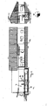
- Fig. 1 shows the valley station of a chairlift.
- the chairlift 2 forming the main conveyor 1 comprises a revolving carrying rope or hoisting rope which is deflected in the station building 2 by means of a reversing device 11, more precisely by means of a reversing carousel 12.
- the boarding area for climbing the chairlift 2 is arranged outside of said station building 22.
- An entry / exit platform 4 is arranged under the uphill running strand of the supporting cable and height adjusted in such a way to the chairlift 2 that its person carrying means 14 run in the form of the chair 15 at a suitable height on the boarding platform 4, see. Fig. 2 ,
- the aforementioned entry / exit platform 4 is assigned as auxiliary conveyor 5 for supplying the persons a conveyor bottom 6, which describes a curved conveyor track 7, as this Fig. 1 shows.
- the access area of the conveyor floor 6 is laterally outside, ie transversely spaced from the swept from the armchair 15 Lane of the chairlift 2.
- a first conveyor section 8 of the conveyor floor 6 leads at an acute angle to the uphill leading conveyor track of the chairlift 2, wherein in the illustrated embodiment said first conveyor section 8 of the conveyor floor 6 at an angle of about 30 ° to the conveying direction of the chairlift 2 this runs, cf. Fig.
- This first conveyor track section 8 thus leads obliquely to the entry area or the entry / exit platform 4, on which the conveyor floor 6 then runs parallel to the conveying direction of the chairlift 2.
- This second conveyor track section 9 of the conveyor floor 6 is connected to the aforementioned first conveyor track section 8 via a third, curved conveyor track section 10 so that overall the conveyor floor is curved in such a way that it initially obliquely feeds onto the conveyor track of the chair lift 2, then in a curve on the conveying direction of the chairlift 2 bends and finally runs a bit far parallel to the conveying direction of the chairlift 2 under the uphill running Seiltrum. Due to this lateral feed of the conveyor floor 6 around the curve, no space is required in the area of the station building 22, which is particularly advantageous if there is limited space in the area of the reversing carousel 12, such as this Fig. 1 shows.
- the access to the access area of the conveyor floor 6 is controlled by a known Zusteigeeinteiler 23, which includes, for example, a hydraulic or electrically actuated barrier.
- the Zusteigeeinteiler 23 can be constructed on a support structure which is firmly connected to the conveyor bottom 6. From the Zusteigeeinteiler 23 of the conveyor floor is mounted at a distance of about one meter, with a run-in ramp with a suitable inclination of about 5 to 10% is installed between the conveyor floor and the Zusteigeeinteiler 23.
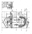
- the conveyor floor 6 can advantageously, as the Fig. 7 to 9 show a belt strap 24 having a plurality of step scales 17, which are formed in the illustrated embodiment in the form of crescent-shaped plate segments, see. Fig. 7 , These crescent-shaped steps 17 overlap each other with their arcuate edges, advantageously the concave preceded by arched edge side and is covered by the bulbous back of the leading tread.
- the step scales 17 may have a width of 10 to 70 cm, preferably about 15 to 30 cm and a length of about 50 cm to 150 cm, preferably about 70 to 90 cm.
- the step scales 17 have on their underside coupling pieces 25 which have eye-shaped connecting pieces in the illustrated embodiment. By means of these eye-shaped connecting pieces adjoining step scales 17 are connected to each other, wherein corresponding connecting rods can be inserted into each other in overlapping eyelets, whereby an endless step scales belt can be mounted.
- the step scales 17 can advantageously be longitudinally displaceably guided in a guide 19 located on the underside of the step scales 17, said guide 19 describing and defining the previously described curved course.
- the steps 17 are rotatable about upright pivot axes 18 so that they can be parallel to the conveyor track 7 of the conveyor floor 6 and parallel to a tangent thereto.
- angle control device 20 is provided, which may for example comprise guide levers which are guided on said guide 19.
- the step scales 17 can also be angularly controlled in that they are guided on two coupling pieces 25, since each step scale 17 is coupled on the one hand to the leading step scale 17 and on the other hand to the trailing step scale 17, so that 17 two guide points result for each step scale , see. Fig. 8 ,
- Fig. 1 shows, according to the illustrated embodiment, several treadmill bands may be arranged side by side, so that, for example, two conveyor lanes are provided by the conveyor bottom 6 in a two-chairlift.
- the attacking on the underside of the steps 17 driving wheels includes, which are advantageously designed in the form of gears that engage in notches or depressions on the underside of the step scales 17. This creates a form-liquid connection for power transmission.
- the treadmill belt 17 is guided laterally.
- On the reverse side are also gears. The diameter of the drive or reversing units can thereby be minimized.
- the drive device may also comprise endlessly revolving, pliable drive means, which may in particular be designed as a round link chain.
- pliable drive means which may in particular be designed as a round link chain.
- flexible belts can also rotate endlessly as drive means.
- pliable pulling means on the underside of the steps 17 can be coupled to these in order to transmit the drive movement to the step scales 17.
- a suitable non-slip structure for example in the form of a roughened surface structure.
- the conveyor belt formed by the step scales 17 of the conveyor floor 6 is positively guided centrally, so that a lateral running of the conveyor belt is impossible. This can be achieved by the guide 19, in which the coupling pieces 25 run.
- the conveyor floor also have a curved belt 24, the links 26 are hinged together about transverse axes and coupled to each other in the manner of a chain zugkraftGermantagend, the members 26 with respect to the transverse axes in Gurtlteilsraum have sufficient clearance to the members 26 to a for Promotion ground level vertical axis to make each other sufficiently rotatable and form the belt buckle 24 curvy.
- the belt strap 24 forms, so to speak even a slippery, band-shaped traction means that can be endlessly driven in a suitable manner and forms a conveyor carpet.
- the links 26 of this fabric strap 24 can form strip-shaped step webs, which are coupled to each other in an articulated manner in a chain-like manner with each other.
- said members 26 may have comb-like arranged articulated lugs 27 which engage in provided on the next respective member joint recesses 28, which are also lined up in a corresponding manner in the transverse direction of the belt side by side.
- each member 26 on the one hand articulated lugs 27 and on the other hand complementary thereto Jicheinbuchtitch 28 which are offset from one another in the transverse direction by a pitching step, so that joint noses 27 and -inbuchtitch 28 comb-like in mesh can, as this Fig. 10 shows.
- Suitable positive engagement means for example in the form of hinge pins and hinge pin pockets, are provided on the articulated noses and indentations, which realize the desired flexibility about the transverse axis and the play in the longitudinal direction, which in turn causes the curved belt 24 to curve.
- individual or all members may preferably be guided at their lateral edges in longitudinal guides, for example in the form of grinding or sliding webs.
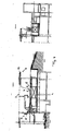
- the conveyor floor 6 is mounted in the entry area of the chairlift 2 as a boarding aid.
- a correspondingly formed conveyor bottom 6 is mounted, as it were, kinematically reversed.
- the conveyor floor 6 initially runs parallel under the chairlift 2 on the exit platform 4, so that the chairlift passengers can ascend accurately to the moving conveyor floor 6. This then leads laterally out of the conveying path of the chairlift 2 with a curved conveyor track section 9.
- conveyor floor section of the conveyor floor 6 leads the skiers or passengers safely out of the effective range of the chairlift 2.
- the conveyor bottom 6 advantageously leads to the reversing carousel of the chairlift 2 so that the area of the mountain station surrounding the reversing carousel 12 is not needed for disembarking the passengers.
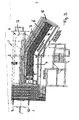
- FIGS. 5 and 6 show a curved curved conveyor floor 7 can also be used as an entry and / or exit aid for a revolving gondola 3 advantageous.
- Fig. 5 shows, can advantageously be provided that the conveyor bottom 6 is guided around the arcuate area around the reversing area of the revolving gondola 3, so that the conveyor bottom 6 at least partially follows the conveying path of the revolving gondolas 16 in the reverse.
- the conveyor floor 6 can be adapted to the conveyor track of the circulating gondolas 16 so that the conveyor floor 6 runs along the sides of the gondolas 16 so that passengers standing on the conveyor floor 6 easily fix skis or snowboards to the gondolas revolving in the reversing area and then into the gondolas can get in. Conversely, passengers can get out of the revolving gondolas on the revolving conveyor floor, without having to start immediately when disembarking, as well as standing on the floor conveyor of the revolving gondolas take away the attached skis or snowboards.
- the conveyor bottom 6 here also has an entry section which supplies at an acute angle to the conveyor track of the circulating gondolas, so that the passengers are automatically guided to the entry area of the circulating gondolas, cf. Fig. 5 , And / or a leading away from the exit area of the revolving gondolas exit section which leads away at an acute angle from the conveyor track of the revolving gondola.
Landscapes
- Engineering & Computer Science (AREA)
- Mechanical Engineering (AREA)
- Transportation (AREA)
- Escalators And Moving Walkways (AREA)
- Handcart (AREA)
- Fittings On The Vehicle Exterior For Carrying Loads, And Devices For Holding Or Mounting Articles (AREA)
- Structure Of Belt Conveyors (AREA)
- Manufacture, Treatment Of Glass Fibers (AREA)
- Motorcycle And Bicycle Frame (AREA)
Priority Applications (1)
| Application Number | Priority Date | Filing Date | Title |
|---|---|---|---|
| PL09001963T PL2096015T3 (pl) | 2008-02-26 | 2009-02-12 | Wyciąg narciarski z ruchomym chodnikiem pomocniczym |
Applications Claiming Priority (1)
| Application Number | Priority Date | Filing Date | Title |
|---|---|---|---|
| DE202008002698U DE202008002698U1 (de) | 2008-02-26 | 2008-02-26 | Skilift mit Hilfsförderboden |
Publications (2)
| Publication Number | Publication Date |
|---|---|
| EP2096015A1 EP2096015A1 (de) | 2009-09-02 |
| EP2096015B1 true EP2096015B1 (de) | 2010-09-22 |
Family
ID=40673582
Family Applications (1)
| Application Number | Title | Priority Date | Filing Date |
|---|---|---|---|
| EP09001963A Not-in-force EP2096015B1 (de) | 2008-02-26 | 2009-02-12 | Skilift mit Hilfsförderboden |
Country Status (7)
| Country | Link |
|---|---|
| US (1) | US20090260949A1 (pl) |
| EP (1) | EP2096015B1 (pl) |
| AT (1) | ATE482125T1 (pl) |
| CA (1) | CA2655387A1 (pl) |
| DE (2) | DE202008002698U1 (pl) |
| ES (1) | ES2353454T3 (pl) |
| PL (1) | PL2096015T3 (pl) |
Cited By (1)
| Publication number | Priority date | Publication date | Assignee | Title |
|---|---|---|---|---|
| DE202016002976U1 (de) | 2016-05-06 | 2017-08-09 | Chairkit Fördertechnik Gmbh | Personenförderanlage |
Families Citing this family (4)
| Publication number | Priority date | Publication date | Assignee | Title |
|---|---|---|---|---|
| AT507310B1 (de) * | 2008-10-09 | 2010-10-15 | Innova Patent Gmbh | Sessel für sessellift |
| CN102275738A (zh) * | 2011-04-26 | 2011-12-14 | 中铁工程设计院有限公司 | 火车站行包邮政自动运输系统 |
| AT515895B1 (de) * | 2014-06-02 | 2016-08-15 | Innova Patent Gmbh | Seilbahnanlage zur Beförderung von Personen |
| IT201700001070A1 (it) * | 2017-01-05 | 2018-07-05 | Leitner Spa | Stazione di un impianto di trasporto a fune |
Family Cites Families (19)
| Publication number | Priority date | Publication date | Assignee | Title |
|---|---|---|---|---|
| US1823010A (en) * | 1927-04-11 | 1931-09-15 | Harry G Traver | Amusement ride |
| US2756686A (en) * | 1950-10-20 | 1956-07-31 | Adamson Stephens Mfg Co | Transportation apparatus |
| GB1018827A (en) | 1961-09-30 | 1966-02-02 | Reiners Walter | Automatic winding machine |
| CH393400A (fr) * | 1963-04-25 | 1965-06-15 | Bouladon Gabriel | Installation de remontée mécanique |
| US3185108A (en) * | 1963-07-10 | 1965-05-25 | C F Butz Engineering | Pedestrian carrier |
| US3498445A (en) * | 1967-10-30 | 1970-03-03 | Stearns Mfg Co | Conveyor drive means |
| US3548753A (en) | 1968-06-18 | 1970-12-22 | Edward M Thurston | Loading means for chair lift |
| AT405271B (de) * | 1995-04-07 | 1999-06-25 | Doppelmayr & Sohn | Seilbahnanlage mit einem um zwei umlenkscheiben geführten trag- und förderseil für fahrbetriebsmittel |
| CA982970A (en) * | 1973-04-13 | 1976-02-03 | David J. Dubeta | Staging and loading device for chair lifts |
| FR2236707A1 (en) * | 1973-07-09 | 1975-02-07 | Pomagalski Sa | Non-stop automatic ski lift cableway - access to loading position is controlled by automatic barriers |
| FR2416821A2 (fr) * | 1977-06-02 | 1979-09-07 | Montagner Rene | Perfectionnement aux procedes et installations d'embarquement de passagers sur une structure porteuse mobile suspendue, notamment de remontee mecanique |
| US4476974A (en) * | 1981-10-19 | 1984-10-16 | Rexnord Inc. | Continuous article handling conveyor |
| US5042648A (en) * | 1989-11-27 | 1991-08-27 | Garvey Corporation | Crescent-type chain conveyor |
| FR2702186B1 (fr) * | 1993-03-05 | 1995-05-05 | Pomagalski Sa | Télésiège à tapis roulant d'embarquement. |
| FR2703315B1 (fr) * | 1993-04-01 | 1995-07-13 | Pomagalski Sa | Dispositif d'embarquement de telesieges. |
| US5361893A (en) * | 1993-11-18 | 1994-11-08 | The Laitram Corporation | High friction plastic conveyor belts having modular links formed by two integrated plastic materials |
| US5664499A (en) * | 1996-08-28 | 1997-09-09 | Kingsmill; William Gault | Ski lift loader and unloader |
| US5911305A (en) * | 1996-11-22 | 1999-06-15 | Span Tech Corporation | Endless loop modular conveyor system with drive screw |
| FR2758511B1 (fr) * | 1997-01-21 | 1999-03-05 | Transports Et | Telesiege a embarquement ameliore |
-
2008
- 2008-02-26 DE DE202008002698U patent/DE202008002698U1/de not_active Expired - Lifetime
-
2009
- 2009-02-12 AT AT09001963T patent/ATE482125T1/de active
- 2009-02-12 PL PL09001963T patent/PL2096015T3/pl unknown
- 2009-02-12 DE DE502009000100T patent/DE502009000100D1/de active Active
- 2009-02-12 EP EP09001963A patent/EP2096015B1/de not_active Not-in-force
- 2009-02-12 ES ES09001963T patent/ES2353454T3/es active Active
- 2009-02-25 CA CA002655387A patent/CA2655387A1/en not_active Abandoned
- 2009-02-25 US US12/380,256 patent/US20090260949A1/en not_active Abandoned
Cited By (2)
| Publication number | Priority date | Publication date | Assignee | Title |
|---|---|---|---|---|
| DE202016002976U1 (de) | 2016-05-06 | 2017-08-09 | Chairkit Fördertechnik Gmbh | Personenförderanlage |
| EP3241797A1 (de) | 2016-05-06 | 2017-11-08 | CHAIRKIT Fördertechnik GmbH | Personenförderanlage |
Also Published As
| Publication number | Publication date |
|---|---|
| ATE482125T1 (de) | 2010-10-15 |
| EP2096015A1 (de) | 2009-09-02 |
| CA2655387A1 (en) | 2009-08-26 |
| PL2096015T3 (pl) | 2011-03-31 |
| DE202008002698U1 (de) | 2009-07-23 |
| ES2353454T3 (es) | 2011-03-02 |
| US20090260949A1 (en) | 2009-10-22 |
| DE502009000100D1 (de) | 2010-11-04 |
Similar Documents
| Publication | Publication Date | Title |
|---|---|---|
| DE3104740C2 (pl) | ||
| DE4243812C2 (de) | Schiffs-Förderanlage | |
| EP2096015B1 (de) | Skilift mit Hilfsförderboden | |
| EP1026061A2 (de) | Anlage zur Bewegung von Personen von einer Bergstation in eine Talstation | |
| EP1849674A1 (de) | Seilbahnanlage mit an ein Förderseil ankuppelbaren Fahrbetriebsmitteln | |
| EP0033294A2 (de) | Fördersystem für einen Treppenlift | |
| EP0430091B1 (de) | Einrichtung zur Einsteighilfe bei kontinuierlich umlaufenden Seilbahnen | |
| DE2358258C2 (de) | Gliederbandförderer für den Personen- und Stückguttransport | |
| EP1757348B1 (de) | Vorrichtung zum Anheben von Fahrzeugen, insbesondere Booten oder dergleichen | |
| DE4023585C1 (en) | Conveyor system for goods - has laterally displaced and non-overlapping guide tracks | |
| DE10340867A1 (de) | Fördersystem, insbesondere eine Flughafen-Gepäckförderanlage, und Führungsmittel für ein solches Fördersystem | |
| DE842614C (de) | Volksbelustigungseinrichtung zum Befoerdern von Personen auf einer schiefen Ebene mittels Foerderband | |
| DE3142790C2 (pl) | ||
| DE2414629A1 (de) | Foerdervorrichtung, insbesondere rollsteig, mit variabler geschwindigkeit | |
| DE914478C (de) | Plattenbandfoerderer | |
| EP1550595B1 (de) | Fahrgasthängesystem für Seilschwebebahnen | |
| DE3639826A1 (de) | Bandfoerderer fuer linienfuehrungen mit abbiegungen in horizontaler, vertikaler und sphaerischer richtung | |
| EP0768272A2 (de) | Fahrgastförderband | |
| DE2413491A1 (de) | Handlauf fuer einen foerderer | |
| AT410756B (de) | Sportanlage mit einer schanze | |
| AT8338U1 (de) | Fördereinrichtung für schiläufer oder snowboardfahrer | |
| EP0423414A1 (de) | Einrichtung zum Praeparieren der Aufsprungbahn einer Skisprungschanze | |
| DE846105C (de) | Personenfoerderbahn fuer Hin- und Herverkehr zwischen zwei Stellen | |
| DE19512612C2 (de) | Absteigevorrichtung für Gurtförderer | |
| DE9217605U1 (de) | Schiffs-Förderanlage |
Legal Events
| Date | Code | Title | Description |
|---|---|---|---|
| PUAI | Public reference made under article 153(3) epc to a published international application that has entered the european phase |
Free format text: ORIGINAL CODE: 0009012 |
|
| AK | Designated contracting states |
Kind code of ref document: A1 Designated state(s): AT BE BG CH CY CZ DE DK EE ES FI FR GB GR HR HU IE IS IT LI LT LU LV MC MK MT NL NO PL PT RO SE SI SK TR |
|
| AX | Request for extension of the european patent |
Extension state: AL BA RS |
|
| 17P | Request for examination filed |
Effective date: 20100226 |
|
| GRAP | Despatch of communication of intention to grant a patent |
Free format text: ORIGINAL CODE: EPIDOSNIGR1 |
|
| AKX | Designation fees paid |
Designated state(s): AT BE BG CH CY CZ DE DK EE ES FI FR GB GR HR HU IE IS IT LI LT LU LV MC MK MT NL NO PL PT RO SE SI SK TR |
|
| RIC1 | Information provided on ipc code assigned before grant |
Ipc: B66B 23/10 20060101ALI20100326BHEP Ipc: B61B 12/02 20060101AFI20100326BHEP Ipc: B66B 23/08 20060101ALI20100326BHEP |
|
| GRAS | Grant fee paid |
Free format text: ORIGINAL CODE: EPIDOSNIGR3 |
|
| GRAA | (expected) grant |
Free format text: ORIGINAL CODE: 0009210 |
|
| AK | Designated contracting states |
Kind code of ref document: B1 Designated state(s): AT BE BG CH CY CZ DE DK EE ES FI FR GB GR HR HU IE IS IT LI LT LU LV MC MK MT NL NO PL PT RO SE SI SK TR |
|
| REG | Reference to a national code |
Ref country code: GB Ref legal event code: FG4D Free format text: NOT ENGLISH |
|
| REG | Reference to a national code |
Ref country code: CH Ref legal event code: EP Ref country code: CH Ref legal event code: NV Representative=s name: BOVARD AG PATENTANWAELTE |
|
| REG | Reference to a national code |
Ref country code: IE Ref legal event code: FG4D Free format text: LANGUAGE OF EP DOCUMENT: GERMAN |
|
| REF | Corresponds to: |
Ref document number: 502009000100 Country of ref document: DE Date of ref document: 20101104 Kind code of ref document: P |
|
| PG25 | Lapsed in a contracting state [announced via postgrant information from national office to epo] |
Ref country code: NO Free format text: LAPSE BECAUSE OF FAILURE TO SUBMIT A TRANSLATION OF THE DESCRIPTION OR TO PAY THE FEE WITHIN THE PRESCRIBED TIME-LIMIT Effective date: 20101222 Ref country code: FI Free format text: LAPSE BECAUSE OF FAILURE TO SUBMIT A TRANSLATION OF THE DESCRIPTION OR TO PAY THE FEE WITHIN THE PRESCRIBED TIME-LIMIT Effective date: 20100922 Ref country code: LT Free format text: LAPSE BECAUSE OF FAILURE TO SUBMIT A TRANSLATION OF THE DESCRIPTION OR TO PAY THE FEE WITHIN THE PRESCRIBED TIME-LIMIT Effective date: 20100922 |
|
| REG | Reference to a national code |
Ref country code: NL Ref legal event code: VDEP Effective date: 20100922 |
|
| LTIE | Lt: invalidation of european patent or patent extension |
Effective date: 20100922 |
|
| PG25 | Lapsed in a contracting state [announced via postgrant information from national office to epo] |
Ref country code: HR Free format text: LAPSE BECAUSE OF FAILURE TO SUBMIT A TRANSLATION OF THE DESCRIPTION OR TO PAY THE FEE WITHIN THE PRESCRIBED TIME-LIMIT Effective date: 20100922 Ref country code: SI Free format text: LAPSE BECAUSE OF FAILURE TO SUBMIT A TRANSLATION OF THE DESCRIPTION OR TO PAY THE FEE WITHIN THE PRESCRIBED TIME-LIMIT Effective date: 20100922 |
|
| REG | Reference to a national code |
Ref country code: ES Ref legal event code: FG2A Effective date: 20110218 |
|
| REG | Reference to a national code |
Ref country code: SK Ref legal event code: T3 Ref document number: E 8422 Country of ref document: SK |
|
| PG25 | Lapsed in a contracting state [announced via postgrant information from national office to epo] |
Ref country code: SE Free format text: LAPSE BECAUSE OF FAILURE TO SUBMIT A TRANSLATION OF THE DESCRIPTION OR TO PAY THE FEE WITHIN THE PRESCRIBED TIME-LIMIT Effective date: 20100922 Ref country code: GR Free format text: LAPSE BECAUSE OF FAILURE TO SUBMIT A TRANSLATION OF THE DESCRIPTION OR TO PAY THE FEE WITHIN THE PRESCRIBED TIME-LIMIT Effective date: 20101223 Ref country code: LV Free format text: LAPSE BECAUSE OF FAILURE TO SUBMIT A TRANSLATION OF THE DESCRIPTION OR TO PAY THE FEE WITHIN THE PRESCRIBED TIME-LIMIT Effective date: 20100922 |
|
| REG | Reference to a national code |
Ref country code: PL Ref legal event code: T3 Ref country code: CH Ref legal event code: PFA Owner name: CHAIRKID FOERDERTECHNIK GMBH Free format text: CHAIRKID FOERDERTECHNIK GMBH#BRIXENTALER STRASSE 59#6300 WOERGL (AT) -TRANSFER TO- CHAIRKID FOERDERTECHNIK GMBH#BRIXENTALER STRASSE 59#6300 WOERGL (AT) |
|
| REG | Reference to a national code |
Ref country code: IE Ref legal event code: FD4D |
|
| PG25 | Lapsed in a contracting state [announced via postgrant information from national office to epo] |
Ref country code: IE Free format text: LAPSE BECAUSE OF FAILURE TO SUBMIT A TRANSLATION OF THE DESCRIPTION OR TO PAY THE FEE WITHIN THE PRESCRIBED TIME-LIMIT Effective date: 20100922 |
|
| PG25 | Lapsed in a contracting state [announced via postgrant information from national office to epo] |
Ref country code: EE Free format text: LAPSE BECAUSE OF FAILURE TO SUBMIT A TRANSLATION OF THE DESCRIPTION OR TO PAY THE FEE WITHIN THE PRESCRIBED TIME-LIMIT Effective date: 20100922 Ref country code: PT Free format text: LAPSE BECAUSE OF FAILURE TO SUBMIT A TRANSLATION OF THE DESCRIPTION OR TO PAY THE FEE WITHIN THE PRESCRIBED TIME-LIMIT Effective date: 20110124 Ref country code: NL Free format text: LAPSE BECAUSE OF FAILURE TO SUBMIT A TRANSLATION OF THE DESCRIPTION OR TO PAY THE FEE WITHIN THE PRESCRIBED TIME-LIMIT Effective date: 20100922 Ref country code: RO Free format text: LAPSE BECAUSE OF FAILURE TO SUBMIT A TRANSLATION OF THE DESCRIPTION OR TO PAY THE FEE WITHIN THE PRESCRIBED TIME-LIMIT Effective date: 20100922 Ref country code: IS Free format text: LAPSE BECAUSE OF FAILURE TO SUBMIT A TRANSLATION OF THE DESCRIPTION OR TO PAY THE FEE WITHIN THE PRESCRIBED TIME-LIMIT Effective date: 20110122 |
|
| PLBE | No opposition filed within time limit |
Free format text: ORIGINAL CODE: 0009261 |
|
| STAA | Information on the status of an ep patent application or granted ep patent |
Free format text: STATUS: NO OPPOSITION FILED WITHIN TIME LIMIT |
|
| 26N | No opposition filed |
Effective date: 20110623 |
|
| BERE | Be: lapsed |
Owner name: CHAIRKID FORDERTECHNIK GMBH Effective date: 20110228 |
|
| PG25 | Lapsed in a contracting state [announced via postgrant information from national office to epo] |
Ref country code: DK Free format text: LAPSE BECAUSE OF FAILURE TO SUBMIT A TRANSLATION OF THE DESCRIPTION OR TO PAY THE FEE WITHIN THE PRESCRIBED TIME-LIMIT Effective date: 20100922 |
|
| PG25 | Lapsed in a contracting state [announced via postgrant information from national office to epo] |
Ref country code: MC Free format text: LAPSE BECAUSE OF NON-PAYMENT OF DUE FEES Effective date: 20110228 |
|
| REG | Reference to a national code |
Ref country code: DE Ref legal event code: R097 Ref document number: 502009000100 Country of ref document: DE Effective date: 20110623 |
|
| PG25 | Lapsed in a contracting state [announced via postgrant information from national office to epo] |
Ref country code: BE Free format text: LAPSE BECAUSE OF NON-PAYMENT OF DUE FEES Effective date: 20110228 |
|
| PG25 | Lapsed in a contracting state [announced via postgrant information from national office to epo] |
Ref country code: MT Free format text: LAPSE BECAUSE OF FAILURE TO SUBMIT A TRANSLATION OF THE DESCRIPTION OR TO PAY THE FEE WITHIN THE PRESCRIBED TIME-LIMIT Effective date: 20100922 |
|
| PGFP | Annual fee paid to national office [announced via postgrant information from national office to epo] |
Ref country code: TR Payment date: 20120213 Year of fee payment: 4 |
|
| PG25 | Lapsed in a contracting state [announced via postgrant information from national office to epo] |
Ref country code: MK Free format text: LAPSE BECAUSE OF FAILURE TO SUBMIT A TRANSLATION OF THE DESCRIPTION OR TO PAY THE FEE WITHIN THE PRESCRIBED TIME-LIMIT Effective date: 20100922 |
|
| PGFP | Annual fee paid to national office [announced via postgrant information from national office to epo] |
Ref country code: CZ Payment date: 20130122 Year of fee payment: 5 Ref country code: ES Payment date: 20130212 Year of fee payment: 5 |
|
| PG25 | Lapsed in a contracting state [announced via postgrant information from national office to epo] |
Ref country code: CY Free format text: LAPSE BECAUSE OF FAILURE TO SUBMIT A TRANSLATION OF THE DESCRIPTION OR TO PAY THE FEE WITHIN THE PRESCRIBED TIME-LIMIT Effective date: 20100922 Ref country code: LU Free format text: LAPSE BECAUSE OF NON-PAYMENT OF DUE FEES Effective date: 20110212 |
|
| PGFP | Annual fee paid to national office [announced via postgrant information from national office to epo] |
Ref country code: PL Payment date: 20130122 Year of fee payment: 5 Ref country code: SK Payment date: 20130121 Year of fee payment: 5 |
|
| PG25 | Lapsed in a contracting state [announced via postgrant information from national office to epo] |
Ref country code: BG Free format text: LAPSE BECAUSE OF FAILURE TO SUBMIT A TRANSLATION OF THE DESCRIPTION OR TO PAY THE FEE WITHIN THE PRESCRIBED TIME-LIMIT Effective date: 20101222 |
|
| GBPC | Gb: european patent ceased through non-payment of renewal fee |
Effective date: 20130212 |
|
| PG25 | Lapsed in a contracting state [announced via postgrant information from national office to epo] |
Ref country code: HU Free format text: LAPSE BECAUSE OF FAILURE TO SUBMIT A TRANSLATION OF THE DESCRIPTION OR TO PAY THE FEE WITHIN THE PRESCRIBED TIME-LIMIT Effective date: 20100922 |
|
| PG25 | Lapsed in a contracting state [announced via postgrant information from national office to epo] |
Ref country code: GB Free format text: LAPSE BECAUSE OF NON-PAYMENT OF DUE FEES Effective date: 20130212 |
|
| PG25 | Lapsed in a contracting state [announced via postgrant information from national office to epo] |
Ref country code: CZ Free format text: LAPSE BECAUSE OF NON-PAYMENT OF DUE FEES Effective date: 20140212 |
|
| REG | Reference to a national code |
Ref country code: SK Ref legal event code: MM4A Ref document number: E 8422 Country of ref document: SK Effective date: 20140212 |
|
| PG25 | Lapsed in a contracting state [announced via postgrant information from national office to epo] |
Ref country code: SK Free format text: LAPSE BECAUSE OF NON-PAYMENT OF DUE FEES Effective date: 20140212 |
|
| REG | Reference to a national code |
Ref country code: ES Ref legal event code: FD2A Effective date: 20150330 |
|
| PG25 | Lapsed in a contracting state [announced via postgrant information from national office to epo] |
Ref country code: ES Free format text: LAPSE BECAUSE OF NON-PAYMENT OF DUE FEES Effective date: 20140213 |
|
| PG25 | Lapsed in a contracting state [announced via postgrant information from national office to epo] |
Ref country code: PL Free format text: LAPSE BECAUSE OF NON-PAYMENT OF DUE FEES Effective date: 20140212 |
|
| REG | Reference to a national code |
Ref country code: PL Ref legal event code: LAPE |
|
| PG25 | Lapsed in a contracting state [announced via postgrant information from national office to epo] |
Ref country code: TR Free format text: LAPSE BECAUSE OF NON-PAYMENT OF DUE FEES Effective date: 20130212 |
|
| REG | Reference to a national code |
Ref country code: FR Ref legal event code: PLFP Year of fee payment: 8 |
|
| REG | Reference to a national code |
Ref country code: FR Ref legal event code: PLFP Year of fee payment: 9 |
|
| REG | Reference to a national code |
Ref country code: FR Ref legal event code: PLFP Year of fee payment: 10 |
|
| PGFP | Annual fee paid to national office [announced via postgrant information from national office to epo] |
Ref country code: FR Payment date: 20210223 Year of fee payment: 13 Ref country code: CH Payment date: 20210222 Year of fee payment: 13 Ref country code: IT Payment date: 20210226 Year of fee payment: 13 |
|
| PGFP | Annual fee paid to national office [announced via postgrant information from national office to epo] |
Ref country code: AT Payment date: 20210222 Year of fee payment: 13 Ref country code: DE Payment date: 20210224 Year of fee payment: 13 |
|
| REG | Reference to a national code |
Ref country code: DE Ref legal event code: R119 Ref document number: 502009000100 Country of ref document: DE |
|
| REG | Reference to a national code |
Ref country code: CH Ref legal event code: PL |
|
| REG | Reference to a national code |
Ref country code: AT Ref legal event code: MM01 Ref document number: 482125 Country of ref document: AT Kind code of ref document: T Effective date: 20220212 |
|
| PG25 | Lapsed in a contracting state [announced via postgrant information from national office to epo] |
Ref country code: AT Free format text: LAPSE BECAUSE OF NON-PAYMENT OF DUE FEES Effective date: 20220212 |
|
| PG25 | Lapsed in a contracting state [announced via postgrant information from national office to epo] |
Ref country code: FR Free format text: LAPSE BECAUSE OF NON-PAYMENT OF DUE FEES Effective date: 20220228 |
|
| PG25 | Lapsed in a contracting state [announced via postgrant information from national office to epo] |
Ref country code: LI Free format text: LAPSE BECAUSE OF NON-PAYMENT OF DUE FEES Effective date: 20220228 Ref country code: DE Free format text: LAPSE BECAUSE OF NON-PAYMENT OF DUE FEES Effective date: 20220901 Ref country code: CH Free format text: LAPSE BECAUSE OF NON-PAYMENT OF DUE FEES Effective date: 20220228 |
|
| PG25 | Lapsed in a contracting state [announced via postgrant information from national office to epo] |
Ref country code: IT Free format text: LAPSE BECAUSE OF NON-PAYMENT OF DUE FEES Effective date: 20220212 |