EP2094471B1 - Method for releasing a lens moulded in a cavity between posterior and anterior mould sections - Google Patents
Method for releasing a lens moulded in a cavity between posterior and anterior mould sections Download PDFInfo
- Publication number
- EP2094471B1 EP2094471B1 EP07821604.1A EP07821604A EP2094471B1 EP 2094471 B1 EP2094471 B1 EP 2094471B1 EP 07821604 A EP07821604 A EP 07821604A EP 2094471 B1 EP2094471 B1 EP 2094471B1
- Authority
- EP
- European Patent Office
- Prior art keywords
- lens
- mould
- mould section
- anterior
- posterior
- Prior art date
- Legal status (The legal status is an assumption and is not a legal conclusion. Google has not performed a legal analysis and makes no representation as to the accuracy of the status listed.)
- Ceased
Links
- 238000000034 method Methods 0.000 title claims description 37
- 238000000465 moulding Methods 0.000 claims description 16
- 230000002093 peripheral effect Effects 0.000 claims description 12
- 239000000853 adhesive Substances 0.000 claims description 10
- 230000001070 adhesive effect Effects 0.000 claims description 10
- 239000000178 monomer Substances 0.000 description 54
- 239000000463 material Substances 0.000 description 22
- 230000008569 process Effects 0.000 description 12
- 230000003287 optical effect Effects 0.000 description 11
- 238000000926 separation method Methods 0.000 description 10
- 239000007789 gas Substances 0.000 description 8
- 239000007788 liquid Substances 0.000 description 6
- 230000006378 damage Effects 0.000 description 5
- 238000004519 manufacturing process Methods 0.000 description 4
- 230000000717 retained effect Effects 0.000 description 4
- 238000005259 measurement Methods 0.000 description 3
- 230000015572 biosynthetic process Effects 0.000 description 2
- 230000007547 defect Effects 0.000 description 2
- 230000014509 gene expression Effects 0.000 description 2
- 230000005484 gravity Effects 0.000 description 2
- 102100026735 Coagulation factor VIII Human genes 0.000 description 1
- 101000911390 Homo sapiens Coagulation factor VIII Proteins 0.000 description 1
- WOBHKFSMXKNTIM-UHFFFAOYSA-N Hydroxyethyl methacrylate Chemical group CC(=C)C(=O)OCCO WOBHKFSMXKNTIM-UHFFFAOYSA-N 0.000 description 1
- 230000001154 acute effect Effects 0.000 description 1
- 230000004075 alteration Effects 0.000 description 1
- 239000007864 aqueous solution Substances 0.000 description 1
- 230000000712 assembly Effects 0.000 description 1
- 238000000429 assembly Methods 0.000 description 1
- 238000005452 bending Methods 0.000 description 1
- 230000008901 benefit Effects 0.000 description 1
- 230000006835 compression Effects 0.000 description 1
- 238000007906 compression Methods 0.000 description 1
- 238000001816 cooling Methods 0.000 description 1
- 238000005336 cracking Methods 0.000 description 1
- 238000011143 downstream manufacturing Methods 0.000 description 1
- 239000008246 gaseous mixture Substances 0.000 description 1
- 239000011261 inert gas Substances 0.000 description 1
- 238000012986 modification Methods 0.000 description 1
- 230000004048 modification Effects 0.000 description 1
- 238000006116 polymerization reaction Methods 0.000 description 1
- 238000003908 quality control method Methods 0.000 description 1
- 230000005855 radiation Effects 0.000 description 1
- 230000009467 reduction Effects 0.000 description 1
- 230000003068 static effect Effects 0.000 description 1
- XLYOFNOQVPJJNP-UHFFFAOYSA-N water Substances O XLYOFNOQVPJJNP-UHFFFAOYSA-N 0.000 description 1
Images


Classifications
-
- B—PERFORMING OPERATIONS; TRANSPORTING
- B29—WORKING OF PLASTICS; WORKING OF SUBSTANCES IN A PLASTIC STATE IN GENERAL
- B29D—PRODUCING PARTICULAR ARTICLES FROM PLASTICS OR FROM SUBSTANCES IN A PLASTIC STATE
- B29D11/00—Producing optical elements, e.g. lenses or prisms
- B29D11/00009—Production of simple or compound lenses
- B29D11/00038—Production of contact lenses
- B29D11/00125—Auxiliary operations, e.g. removing oxygen from the mould, conveying moulds from a storage to the production line in an inert atmosphere
- B29D11/00192—Demoulding, e.g. separating lenses from mould halves
-
- B—PERFORMING OPERATIONS; TRANSPORTING
- B29—WORKING OF PLASTICS; WORKING OF SUBSTANCES IN A PLASTIC STATE IN GENERAL
- B29C—SHAPING OR JOINING OF PLASTICS; SHAPING OF MATERIAL IN A PLASTIC STATE, NOT OTHERWISE PROVIDED FOR; AFTER-TREATMENT OF THE SHAPED PRODUCTS, e.g. REPAIRING
- B29C33/00—Moulds or cores; Details thereof or accessories therefor
- B29C33/44—Moulds or cores; Details thereof or accessories therefor with means for, or specially constructed to facilitate, the removal of articles, e.g. of undercut articles
- B29C33/48—Moulds or cores; Details thereof or accessories therefor with means for, or specially constructed to facilitate, the removal of articles, e.g. of undercut articles with means for collapsing or disassembling
- B29C33/50—Moulds or cores; Details thereof or accessories therefor with means for, or specially constructed to facilitate, the removal of articles, e.g. of undercut articles with means for collapsing or disassembling elastic or flexible
-
- Y—GENERAL TAGGING OF NEW TECHNOLOGICAL DEVELOPMENTS; GENERAL TAGGING OF CROSS-SECTIONAL TECHNOLOGIES SPANNING OVER SEVERAL SECTIONS OF THE IPC; TECHNICAL SUBJECTS COVERED BY FORMER USPC CROSS-REFERENCE ART COLLECTIONS [XRACs] AND DIGESTS
- Y10—TECHNICAL SUBJECTS COVERED BY FORMER USPC
- Y10S—TECHNICAL SUBJECTS COVERED BY FORMER USPC CROSS-REFERENCE ART COLLECTIONS [XRACs] AND DIGESTS
- Y10S425/00—Plastic article or earthenware shaping or treating: apparatus
- Y10S425/808—Lens mold
Definitions
- This present invention relates to a method for releasing a moulded lens from a cast mould, according to claim 1.
- the basic process for cast moulding a lens is as follows.
- a quantity of liquid lens material 16 is dispensed onto the concave optical surface 12A of the anterior mould section 12 ( Figure. 1 ), and the posterior mould section 14 is seated upon the anterior mould section 12 with the concave and convex surfaces 14A and 12A thereof, respectively, facing one another to form a lens-shaped mould cavity.
- the joined anterior and posterior mould sections form a single mould which is subjected to a curing cycle (e.g., by thermal or UV radiation) thereby causing polymerization of the lens material in the mould cavity ( Figure. 2 ).
- a number of steps must be carried out in order to retrieve the cured lens from the mould cavity.
- the posterior and anterior mould sections must be separated to retrieve the cured lens. This procedure is sometimes referred to as 'decapping' in the art.
- the opening or release of the mould sections must be carried out in a manner which will not harm the delicate lens.
- the lens and any excess lens material will adhere to the opposing concave and convex mould surfaces.
- the force required to release the posterior mould section from the anterior mould section must be strong enough to break the adhesive bond of the lens and excess lens material to the opposing mould surfaces, yet not so forceful or haphazard that the optical surfaces of the lens are harmed by the release process.
- the apparatus includes a first device for applying steam to the concave non-optical surface of the posterior mould part to provide a temperature gradient from the posterior mould part to the anterior mould part and a second device comprising pry fingers for inserting between the circumferential flanges and pulling the mould parts apart.
- the provision of the temperature gradient is undesirable for the cured lens since the lens can deform and not re-gain its required curvature upon cooling. If the separation is attempted without providing the temperature gradient, there is a risk that the lens will be damaged. Furthermore, there is no guarantee that the cured lens will remain adhered to the desired mould part upon the separation step.
- Another arrangement separating the mould parts apart is disclosed in US 5,693,268 (Widman et al. ) in which the mould parts are pulled apart by inserting wedges therebetween.
- the hollow cylinder instead of the annular end surface, has a pointed edge formed by tapered inner and outer surfaces of the cylinder. The edge is inserted between the inner and outer surfaces of the skirts of the posterior and anterior mould sections respectively, thereby radially deflecting the skirt of the posterior mould section and causing the posterior mould section to disengage from the lens.
- the deflection amplitude of the skirt of the posterior mould section is limited, which in turn limits the control over the posterior mould during the decapping operation.
- U.S. Application Publication No. 2003/0160343 describes a separation module in which the mould parts are oriented so that the anterior mould section 12 ( Figure 3 ) is upper-most in relation to the posterior, convex mould part 14.
- An annular flange 14c of the posterior mould part 14 rests on a support plate 260 and a means is provided for striking the anterior mould part 12 from above at an annular flange 12c so as to break the adhesion bond between the mould parts 12,14.
- the posterior mould part 14 is located upper-most in relation to the anterior mould part 12 and the anterior mould part is supported from below on posts.
- a means is provided for striking from above the annular surface surrounding the lens forming surface of the posterior mould part 14 so as to break the bond between the mould parts.
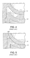
- the quantity of liquid lens material dispensed in the anterior mould section is purposely greater than that needed to form the lens ( Figure 4 ).
- the excess liquid lens material 180 is expelled from the mould cavity ( Figure 5 ).
- This excess liquid is typically held in a "reservoir", a groove or a flange surrounding the mould cavity, and is cured along with the lens.
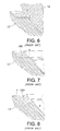
- the cured excess material 180 is typically referred to as a "monomer ring" or a "HEMA ring” in the contact lens art, depending on the specific lens material used.
- the term "monomer ring” will be used herein for convenience, although it is understood this term is used broadly herein to cover any type of lens material employed.
- the monomer ring will usually adhere to one of the mould sections, typically the anterior section 12, with the monomer ring usually retained in the anterior mould section 12 along with the lens ( Figures 6 and 7 ).
- the lens edge will likely become damaged due to interference with the monomer ring ( Figure 8 ).
- the presence of the monomer ring can also interfere with downstream processes and machinery. It is thus desirable to release and remove the monomer ring from the anterior mould section prior to the release and removal of the lens therefrom.
- U.S. Patent Application Publication 2006/0071356-A1 (Beebe ) describes a tooling for removing excess monomer material from the anterior mould part.
- the tooling comprises a plate in a surface of which there is formed a wedge-shaped groove which has a first pair of opposed tapered surfaces that guide the anterior mould part as it is moved through the groove.
- the wedge-shaped groove also has a second pair of opposed tapered surfaces that contact and deflect the monomer ring material as the anterior mould part is guided by the first pair of tapered surfaces, thereby displacing and removing the excess material from the anterior mould part while the cured lens remains adhered to the anterior mould part.
- the '875 device there still remains a problem that pieces of the monomer ring may remain adhered to the anterior mould part and that some pieces may become loose and interfere with the cured lens or with the tooling.
- the lens will adhere to a surface of one of the mould sections and must therefore be released from the mould section on which it is retained. As mentioned above, the lens typically remains adhered to the anterior mould section.
- Both wet and dry release methods of lens release have been proposed in the prior art. In wet lens release methods, an aqueous solution is used to wet the hydrophilic lens which absorbs water and swells, causing the lens to separate from the mould surface. In dry release methods, the lens is removed from the associated mould surface while still in the dry state. In general, dry releasing a lens from the associated mould part is preferred over wet release methods. This is because the lens is much easier to handle when in the dry state as opposed to the wet state.
- WO 2004/030898 discloses a method and an apparatus for dry releasing of the anterior, convex surface of a lens from an anterior mould part 12 ( Figure. 10 ) which involves applying a first force to peripheral regions of the convex non-optical surface 12D of the anterior mould part, and subsequently applying a second force against an apex region 12E of the non-optical convex surface.
- WO 2005/061212 (Bausch & Lomb Inc.) teaches a method and an apparatus for dry-releasing a cured lens from the anterior mould part 12 (see Figure. 11 ) comprising a servo-driven lens release head 19 positionable in register with the anterior mould part 12 and having a downwardly facing annulus 19a.
- a pin 280 is placed beneath an apex portion of the non-optical convex surface 12e of the anterior mould part.
- WO 98/19854 also discloses a method for separating mould sections from a lens whilst minimizing lens damage and for ensuring that the lens is retained initially in a selected mould section.
- the lens is retrieved, for example by a vacuum picking tool.
- the lens When releasing a lens from its associated mould in the dry state, the lens will necessarily absorb some of the force used against the mould to release the lens therefrom.
- the force used to release the lens from the mould must be of a force strong enough to break the adhesive bond between the lens and the opposing mould surface, yet not so forceful or haphazard that the optical surfaces of the lens are harmed by the release process.
- the lens should the lens crack or be otherwise damaged during the lens release process, the lens must be rejected, thereby lowering the output yield and increasing manufacturing costs.
- the above dry release methods are satisfactory in certain mould part/lens combinations of materials and designs, they have proven unsatisfactory in instances where, for example, the mould part is formed of a relatively rigid material which makes it harder to deform the mould part relative to the lens to which it is adhered without harming the lens in the process.
- This situation is particularly acute when the lens is a toric lens which includes indicia in the lens surface which tend to adhere to the mould part more strongly than the surrounding smooth surface of the lens.
- Releasing a lens of this type in the dry state can cause cracking particularly adjacent the toric markings of the lens.
- the above methods are associated with the risk of damaging the edge of the lens.
- the invention provides a method of releasing peripheral regions of a curved lens adhered to a concave moulding surface of a mould section as claimed in the appended claims.
- the longitudinal spacing between the posterior mould section and the second support element is achieved by sufficiently spacing apart the first and the second faces along the longitudinal axis so that when the posterior mould section rests on the first face, the second face is spaced apart form the anterior mould section.
- a gap is defined between the radially inwardly directed face of the first support element and the radially outwardly directed face of the second support element, the gap being configured to receive a skirt portion depending from the anterior mould section.
- the gap is configured so as to accommodate a flange projecting from the skirt portion of the anterior mould section, thereby further providing for improved flexibility of the mould.
- the first end face is adapted to support at least a peripheral portion of a flange projecting from a skirt portion of the posterior mould section.
- Such an arrangement provides for greater flexibility of the mould compared to the prior art devices.
- the flexibility of the mould is required during the operation of decapping, which will be discussed below in greater detail, i.e. separation of the anterior mould section from the posterior mould section.
- the second support element is configured with respect to the skirt portion of the anterior mould section so as to be received within the skirt portion. More specifically, the second support element is preferably configured with respect to the skirt portion of the anterior mould section so that when the second support element is received within the skirt, a sufficient spacing is provided between inner surfaces of the skirt and outer surfaces of the second support element to provide a clearance for deformation of the skirt in the radial direction.
- the second face is configured to abut an outer convex surface of the anterior mould section. This abutment occurs after the posterior and the anterior mould sections have been separated from each other and, since the anterior mould section is not supported by anything, apart from being adhered to the posterior mould section, the anterior mould section drops onto the second face.
- the anterior mould section drops under the influence of gravity which may be assisted by vacuum.
- the second face is in a form of an annular surface surrounding an aperture formed in the second support element such that when the outer convex surface of the posterior mould section abuts the annular surface, a portion of the outer convex surface projects into the aperture the aperture being sized and shaped so that the outer convex surface remains spaced apart from surfaces defining the aperture.
- the annular surface serves to support the anterior mould section during the operations of removing the monomer ring (i.e. the excess material expelled from the moulding cavity into a reservoir between mutually facing surfaces of the mould sections surrounding the cured lens) and releasing the lens from the anterior mould section. These operations will be discussed below in greater detail.
- the annular surface serves as a bearing surface for bending of the anterior mould section during those operations when a longitudinally directed force is applied to the flange of the skirt of the anterior mould section.
- the aperture of the second support element may be in a form of a bore.
- the first support element comprises a pair of diametrically opposing shoulders, preferably arcuate, but not limited thereto.
- the shoulders ideally project proud from an end surface of the post in the longitudinal direction.
- each shoulder comprises a slot formed in the radially inwardly facing face of the shoulder, the slot being configured to receive at least a peripheral portion of the flange of the anterior mould section upon radial outward deflection (discussed below) of adjacent portions of the skirt of the anterior mould section during the operations of removing the monomer ring and releasing the lens from the anterior mould section.
- the slot may be either through or blind as long as it is configured to accommodate the deflected flange.
- the second support element and the gap between the radially inwardly directed face of the first support element and the radially outwardly directed face of the second support element are configured with respect to the anterior mould section so that when the anterior mould section rests on the second face, the flange of the skirt of the anterior mould section is suspended within the gap, i.e. does not come into contact with any of the surrounding surfaces. This provides the flange with the necessary freedom to flex during the application thereto of the longitudinal force.
- the second support element comprises a pillar located substantially centrally between the shoulders.
- the pillar ideally projects proud from the end surface of the post in the longitudinal direction, i.e. in the same direction as the shoulders.
- the second face may comprise a chamfer formed between an end surface of the pillar and an inner surface defining the aperture.
- other configurations of the second face are envisaged within the scope of the invention, such as for example an annular rounded edge.
- the pillar preferably comprises a pair of diametrically opposing flats on an outer surface of the pillar so as to provide a clearance for radial inward deformation of the skirt of the anterior mould section when the anterior mould section rests on the second face.
- the radial inward deformation occurs during the operations of removing the monomer ring and releasing the lens from the anterior mould section when a longitudinal force is applied to a pair of diametrically opposed portions of the flange of the anterior mould section causing adjacent skirt portions to deflect towards the longitudinal axis.
- the radial inward deformation of these portions at the skirt causes two other diametrically opposed portions thereof perpendicular to the first two portions to deflect radially outwardly, as discussed above.
- the post ideally comprises a pair of diametrically opposing flats on an outer surface of the post to prevent rotation of the post in a pallet.
- Other known means for preventing rotation of the post are also envisaged.
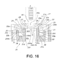
- Figure 16 shows a typical mould 2 for cast moulding an ophthalmic lens.
- the mould 2 comprises a posterior mould section 21 for forming the posterior, i.e. the concave lens surface and an anterior mould section 22 for forming the anterior, i.e. the convex lens surface.
- the mould sections 21 and 22 include respective tubular skirts 23 and 24.
- the inner diameter of the skirt 23 is larger than the outer diameter of the skirt 24 so that the skirt 24 can be received in the skirt 23.
- Each skirt 23 and 24 has a radially projecting flange 20 and 200, respectively.
- Each flange 20, 200 has and end face 20a and 200a, respectively and a back face 20b, 200b, respectively.
- a gap 25 is defined between the inner and outer surfaces of the skirts 23 and 24, respectively, to provide a clearance to enable the outer skirt 23 to flex as will be described below.
- the mould 2 is shown with a lens 10 having already been formed (in accordance with a typical moulding process described above) and cured between an inner convex surface 27 of the posterior mould section 21 and an inner concave surface 26 of the anterior mould section 22.
- a gap 28 is defined between annular surfaces 21c and 22c of the posterior and anterior mould sections, respectively, surrounding their respective surfaces 27 and 26.
- the gap 28 serves as a reservoir for receiving excess lens material expelled from the mould cavity during the formation of the lens 10.
- the excess material 11 is typically referred to in the art as "monomer ring”.
- the mould sections 21, 22 need to be separated from each other. This operation is typically referred to in the art as "decapping".
- Figure 16 illustrates an assembly for decapping the mould 2.
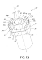
- the assembly comprises a support post 30 on which the mould 2 is located.
- the post 30 is preferably adapted to be placed on a pallet (not shown) for carrying a plurality of such supporting posts.
- the support post 30 comprises a longitudinal axis 32 and a first supporting element in the form of a pair of opposing shoulders 31 radially outwardly spaced from the longitudinal axis 32.
- expressions 'longitudinal(ly)', 'longitudinally directed', 'in the longitudinal direction' etc., 'diametrically', 'radially' etc. should be understood to be used in relation to the longitudinal axis 32.
- Each shoulder 31 projects proud from a base face 38 of the post 30 and has a first end face 31a and an inwardly radially facing face 31b.
- the post 30 also comprises a second supporting element in the form of a pillar 33 located substantially centrally between the shoulders 31 and projecting proud from the base face 38 of the post 30.
- the pillar 33 has a second end face 33a and a radially outwardly facing face 33b.
- the shoulders 31 and the pillar 33 are parts of the same element.
- Separate posts may be provided, one for supporting the posterior mould section 21 and the other for supporting the anterior mould section 22. Also, the supporting post 30 and shoulders 31 are immovable with respect to one another.
- the shoulders 31 can be movably arranged with respect to the pillar 33.
- the shoulders 31 in the presently described embodiment are arcuate and the pillar 33 is in the form of a substantially cylindrical tube.
- a gap 34 is defined by the inwardly facing face 31b of each shoulder 31, the outwardly facing face 33b of the pillar 33 and the base face 38 of the post.
- the dimensions of the shoulders 31, the pillar 33 and the gap 34 are selected with respect to the mould 2 such that when the flange 20 rests on the first end faces 31 a, an outer face 22a of the anterior mould section surrounding the curved (i.e. the mould cavity forming) portion 290 of the anterior mould section and the second end face 33a are spaced apart.
- the anterior mould section 22 does not come into contact with any of the surrounding surfaces, except the anterior lens surface to which it is adhered. This spacing provides the outer skirt 23 with freedom to flex during the decapping operation.
- the pillar 33 comprises a tubular wall 33e which has an inner surface 33f which defines an inner bore 33c.
- the inner bore 33c is sized and shaped so as to at least partially accommodate the curved portion 290 of the anterior mould section 22. It will be appreciated that instead of the bore 33c e.g. a suitably shaped blind recess may be provided. If the post 30 is to be used in a pallet for handling a plurality of such posts, a pair of diametrically opposing flats 35 may be provided on the outer surface of the post 30 to prevent rotation of the post in the pallet. Various other means usual in the art may alternatively be provided for securing the post 30 in the pallet.
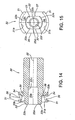
- the decapping assembly further comprises a pin 40 positionable against an outer concave surface 29a of the curved (i.e. the mould cavity forming) portion 29 of the posterior mould section 21.
- the pin 40 has a rounded free end 40a to enable a surface contact between the free end 40a and a central region of the outer concave surface 29a.
- the pin 40 is movable and the post 30 remains stationary.
- the free end 40a of the pin 40 applies a longitudinally directed force to the central portion of the outer concave surface 29a.
- the first end faces 31 a of the shoulders 31 apply a counteractive force against the end face 20a of the flange 20 of the posterior mould section 21. Consequently, the mould 2 is compressed between the free end 40a of the pin 40 and the first end faces 31 a of the shoulders 31.
- the compression force deforms the curved part 29 of the posterior mould section and breaks the adhesive bond between the lens-forming convex surface 27 of the posterior mould section 21 and the concave posterior surface of the lens 10.
- the adhesive bond starts to break initially at the periphery of the lens 10 and continues to break towards the centre of the lens.
- the posterior mould section 21 thereby "peels" away or separates from the lens and from the anterior mould section 22 so that the lens 10 remains adhered to the lens-forming concave surface 26 of the anterior mould section 22.
- the monomer ring 11 remains adhered to an annular surface 22c of the anterior mould section 22 surrounding the lens-forming concave surface 26.
- the separated posterior mould section 21 can then be taken away by suitable instrument such as a vacuum picker or a gripping tool.
- the anterior mould section 22 (since it is only held by the adhesive bond with the lens 10) falls under the influence of gravity onto the pillar 33 so that a region of an outer convex surface 290a of the curved portion 290 abuts an annular surface or a chamfer 33d formed between the second end face 33a of the pillar 33 and the inner surface 33f thereby positioning the posterior mould section 22 for the subsequent operations of removing the monomer ring 11 and releasing the lens 10 from the posterior mould section 22. Only an annular region of the outer convex surface 290a abuts the chamfer 33d. The remaining portion of the convex surface 290a surrounded by the chamfer 33d projects into the bore 33c.
- a square, rounded or otherwise suitably shaped edge may be provided instead of the chamfer 33d.
- the outer diameter of the pillar 33 is sufficiently smaller than the inner diameter of the skirt 24 firstly, to enable a substantially snug-free advancement of the anterior mould section 22 towards the pillar 33 and secondly, to allow the anterior mould section 22 to flex during the operations of removing the monomer ring 11 and releasing the lens 10 from the anterior mould section 22, which will be described below.
- the monomer ring removing and lens edge releasing assembly comprises the above-described supporting post 30.
- the pillar 33 and the shoulders 31 are sized and configured with respect to the anterior mould section 22 so that when the convex surface 290a of the anterior mould section 22 rests on the chamfer 33d, the end face 200a of the flange 200 is spaced sufficiently apart from the surrounding surfaces, in particular the base face 38, so as to enable the flange 200 to flex upon application thereto of a longitudinally directed force as will be described below. Also, whilst the convex surface 290a abuts the chamfer 33d, the outer face 22a and the second end face 33a remain spaced apart. This latter arrangement allows the anterior mould section 22 to flex about the annular region of contact between the chamfer 33d and the convex surface 290a.
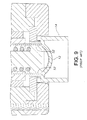
- the assembly further comprises a collar unit 50 which in use is positioned adjacent the anterior mould section 22.
- the collar unit 50 comprises a substantially tubular wall 51 an inner surface 51a of which defines an inner bore 51b.
- the wall 51 encompasses the lens-forming concave surface 26 of the posterior mould section 22 together with the lens 10 and with the monomer ring 11 around the lens 10.
- a number of gas supply apertures 53 are formed in an inner surface 51c of the wall 51.
- the gas supply apertures 53 are located on the inner surface 51a so that when the collar unit 50 is brought into a predetermined position adjacent the anterior mould section 22, the apertures 53 are positioned substantially opposite the interface and preferably substantially level with the outer annular surface 22c.
- Each aperture 53 is configured to shape gas passing therethrough into a jet and to direct the jet at an interface between the outer annular surface 22c and the monomer ring 11.
- the apertures may, however, be also located above or/and below the level of the annular surface 22c as long as the jets of gas are directed at the interface.
- the arrangement is configured such that the force applied by the jets of gas is sufficient to break the bond between the monomer ring 11 and the annular surface 22c and to lift and remove the monomer ring 11 from the annular surface 22c.
- eight apertures 53 circumferentially spaced from each other by 45 deg. have been found sufficient.
- a single circumferentially extending slot (not shown) can be formed in the inner surface 51a.
- An example of gas to be used for the monomer ring removal is air, but it will be appreciated that that other inert gas of gaseous mixture can be utilised.
- the collar unit 50 has an end member 52 for applying a longitudinally directed force to the back surface 200b of the flange 200.
- the collar unit 50 as will be described below, is used for both removing the monomer ring 11 and for releasing peripheral regions about the edge of the lens 10 from the posterior mould section 22, but it will be appreciated that the collar unit 50 and the end member 52 may be provided as separate attachments for these two operations.
- the end member 52 comprises a pair of diametrically opposing projections 52a. At the same time when the collar unit is brought into the predetermined position adjacent the anterior mould section for the application of the gas jets, the projections 52a press against the back surface 200b of the flange 200.
- the portions of the flange 200 (together with the adjacent skirt 24 portions) which are in contact with the projections 52a deform and deflect substantially radially inwardly.
- the chamfer 33d of the pillar 33 applies a counteractive force against the outer convex surface 290a of the anterior mould section 22 causing the concave portion 290 and the outer surface 22c to bend about the region of contact between the convex surface 290a and the chamfer 33d.
- This deformation causes the outer annular surface 22c to deflect in the direction of application of the force by the projections 52a thereby breaking the adhesive bond between the monomer ring 11 and the outer annular surface 22c.
- Peripheral regions of the monomer ring 11 thus peel off and stand proud on the annular surface 22c so that a space (not shown) is created therebetween.
- the gas jets When the gas jets are activated, they enter the space created between the monomer ring 11 and the annular surface 22c and separate the remaining portions of monomer ring 11 from the annular surface 22c.
- each shoulder 31 has a slot 36 which can either be through as shown in Figure 14 or blind (not shown).
- the slot is sized and shaped for accommodating the radially outwardly deflecting flange 200 and a portion of the skirt 24.
- a pair of diametrically opposing flats 37 may be provided on the outer surface of the pillar 33.
- vacuum apertures 55 may be provided in the inner surface 51a of the wall 51 longitudinally spaced apart from the anterior mould section 22. The size of the vacuum apertures 55 is sufficient to allow the separated monomer ring 11 to pass therethrough away from the anterior mould section 22 area.
- the peripheral regions about the edge of the lens 10 have to be released from the anterior mould section 22 according to the method of claim 1.
- the lens 10 may be removed by a suitable tool, such as for example, a vacuum picker. Alternatively, the lens 10 may remain in the mould cavity and be transferred together with the post 30 to downstream locations. It is believed that the above described assembly and method of removing the monomer ring 11 and releasing the lens 10 significantly help to reduce the risk of damaging the outer edges of the lens 10. Such damage to the outer edge of the lens is a serious defect which leads to the lens having to be rejected by quality control and discarded.
- the collar unit 50 is movable and the post 30 remains stationary.
- the assembly it is possible to arrange the assembly so that the post 30 is movable and the collar unit 50 remains stationary, or so that both the collar unit 50 and the post 30 can be moved to and from each other.
- the above described assembly is suitable for both removing the monomer ring 11 and releasing the lens edge.
- the method of the invention is not limited to use of the combined assembly.
- the first assembly may comprise the post 30 and the above described collar unit 50 together with the end member 52.
- the second assembly may comprise the post 30 and just the end member 52 for the operation of releasing the lens edge.
- an optimal force should be selected to be applied by the pin 40 to the outer concave surface 29a of the posterior mould section 21.
- an optimal force should be selected to be applied by the opposing projections 52a to the flange 200 of the anterior mould section 22 in order to remove the monomer ring 11 and release the lens edge. Incorrectly selected forces may cause damage to the lens.
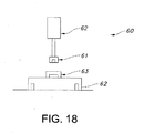
- a force measurement system 60 schematically shown in Figure 18 has been designed.
- the system 60 comprises an interchangeable head 61 connected to either a mechanically driven load cell 62 or a servo (not shown).
- the interchangeable head 16 can be used with the pin 40 to measure an optimal force for decapping, and with the projections 52a to measure the optimal force for removing the monomer ring 11 and releasing the lens edge.
- the system also comprises a means for supporting the mould sections 21, 22 during the measurements which may take the form of a pallet 62.
- the pallet 62 is supplied with interchangeable fixtures 63 (one fixture only is shown in Figure 18 ) for placement of mould sections 21, 22 for the respective operations decapping and removing monomer ring 11/releasing the lens edge.
- the interchangeable fixture 63 is positioned underneath the interchangeable head 31 so that, when received in the interchangeable fixture, the centre of the relevant mould section 21 or 22 is aligned with the interchangeable head.
Landscapes
- Engineering & Computer Science (AREA)
- Mechanical Engineering (AREA)
- Health & Medical Sciences (AREA)
- Manufacturing & Machinery (AREA)
- Ophthalmology & Optometry (AREA)
- Casting Or Compression Moulding Of Plastics Or The Like (AREA)
- Moulds For Moulding Plastics Or The Like (AREA)
- Eyeglasses (AREA)
Applications Claiming Priority (2)
| Application Number | Priority Date | Filing Date | Title |
|---|---|---|---|
| IE2006/0936A IE85335B1 (en) | 2006-12-21 | Apparatus and method for releasing lenses from cast moulds | |
| PCT/EP2007/061240 WO2008074541A1 (en) | 2006-12-21 | 2007-10-19 | Apparatus and method for releasing a lens moulded in a cavity between posterior and anterior mould sections |
Publications (2)
| Publication Number | Publication Date |
|---|---|
| EP2094471A1 EP2094471A1 (en) | 2009-09-02 |
| EP2094471B1 true EP2094471B1 (en) | 2013-04-10 |
Family
ID=38969459
Family Applications (1)
| Application Number | Title | Priority Date | Filing Date |
|---|---|---|---|
| EP07821604.1A Ceased EP2094471B1 (en) | 2006-12-21 | 2007-10-19 | Method for releasing a lens moulded in a cavity between posterior and anterior mould sections |
Country Status (6)
| Country | Link |
|---|---|
| US (2) | US8105070B2 (enExample) |
| EP (1) | EP2094471B1 (enExample) |
| JP (1) | JP5088903B2 (enExample) |
| CN (1) | CN101563213B (enExample) |
| ES (1) | ES2403585T3 (enExample) |
| WO (1) | WO2008074541A1 (enExample) |
Families Citing this family (14)
| Publication number | Priority date | Publication date | Assignee | Title |
|---|---|---|---|---|
| US20070138670A1 (en) * | 2005-12-20 | 2007-06-21 | Bausch And Lomb Incorporated | Method and Apparatus for the Dry Release of a Compliant Opthalmic Article from a Mold Surface |
| CN102123853B (zh) * | 2008-08-20 | 2014-09-10 | 诺华股份有限公司 | 用于从半模上移除眼用透镜的设备 |
| US8313675B2 (en) * | 2009-08-31 | 2012-11-20 | Coopervision International Holding Company, Lp | Demolding of ophthalmic lenses during the manufacture thereof |
| US9457522B2 (en) * | 2013-02-26 | 2016-10-04 | Coopervision International Holding Company, Lp | Methods and apparatus useful in manufacturing lenses |
| WO2015101793A1 (en) * | 2014-01-06 | 2015-07-09 | Coopervision International Holding Company, Lp | Ophthalmic lens manufacturing method and apparatus that include flash removal from lens mold members |
| US9938034B2 (en) | 2014-12-19 | 2018-04-10 | Coopervision International Holding Company, Lp | Method and apparatus relating to manufacture of molds for forming contact lenses |
| US9937640B2 (en) | 2014-12-19 | 2018-04-10 | Coopervision International Holding Company, Lp | Apparatus and method for closure of ophthalmic lens molds |
| US9764501B2 (en) | 2014-12-19 | 2017-09-19 | Coopervision International Holding Company, Lp | Contact lens mold parts, contact lens mold assemblies, and methods of making contact lenses |
| US10029402B2 (en) | 2014-12-19 | 2018-07-24 | Coopervision International Holding Company, Lp | Method and apparatus for manufacturing contact lenses |
| US10137612B2 (en) | 2014-12-19 | 2018-11-27 | Coopervision International Holding Company, Lp | Methods and apparatus for manufacture of ophthalmic lenses |
| WO2018069868A1 (en) * | 2016-10-14 | 2018-04-19 | Novartis Ag | Method for producing contact lenses |
| TWI718469B (zh) * | 2019-01-09 | 2021-02-11 | 優你康光學股份有限公司 | 用於隱形眼鏡脫模的模具及其方法 |
| CN110231209A (zh) * | 2019-06-24 | 2019-09-13 | 中铁十七局集团第二工程有限公司 | 一种注浆用水泥净浆试件制作装置 |
| CN114061811A (zh) * | 2021-11-15 | 2022-02-18 | 江苏万新光学有限公司 | 一种光学镜片模具开模力测量装置 |
Family Cites Families (27)
| Publication number | Priority date | Publication date | Assignee | Title |
|---|---|---|---|---|
| GB796825A (en) | 1955-10-04 | 1958-06-18 | American Optical Corp | Improvements in or relating to casting devices for optical elements |
| US4190621A (en) * | 1977-03-10 | 1980-02-26 | Martin Greshes | Method for molding optical plastic lenses of the standard and bifocal type |
| US4474355A (en) * | 1977-06-27 | 1984-10-02 | Martin Greshes | Apparatus for molding optical plastic lenses of the standard and bifocal type |
| US4254065A (en) * | 1979-04-04 | 1981-03-03 | Ratkowski Donald J | Injection molding of contact lenses |
| US5271875A (en) | 1991-09-12 | 1993-12-21 | Bausch & Lomb Incorporated | Method for molding lenses |
| US5316700A (en) * | 1992-11-02 | 1994-05-31 | Wesley-Jessen Corporation | Method and apparatus for removing excess lens forming material |
| US5850107A (en) * | 1994-06-10 | 1998-12-15 | Johnson & Johnson Vision Products, Inc. | Mold separation method and apparatus |
| US5836323A (en) * | 1994-06-10 | 1998-11-17 | Johnson & Johnson Vision Products, Inc. | Automated method and apparatus for hydrating soft contact lenses |
| JPH08323780A (ja) * | 1995-06-01 | 1996-12-10 | Olympus Optical Co Ltd | 複合型光学素子の離型方法および装置 |
| AU706496B2 (en) * | 1995-11-21 | 1999-06-17 | Johnson & Johnson Vision Products, Inc. | Infra-red heat source for demolding contact lenses |
| US5693268A (en) * | 1996-04-01 | 1997-12-02 | Johnson & Johnson Vision Products, Inc. | Wedge demolding of cast lens mold assemblies |
| US5820895A (en) * | 1996-06-04 | 1998-10-13 | Johnson & Johnson Vision Products, Inc. | Conductive probe for heating contact lens mold assemblies during demolding |
| KR20000053099A (ko) | 1996-11-06 | 2000-08-25 | 스티븐 에이. 헬렁 | 콘택트 렌즈 주형부들을 분리시키기 위한 방법 및 장치 |
| AU5289498A (en) * | 1997-02-05 | 1998-08-13 | Johnson & Johnson Research Pty. Limited | Basecurve mold designs to maintain HEMA ring/basecurve adhesion |
| US6558584B1 (en) * | 2000-03-31 | 2003-05-06 | Bausch & Lomb Incorporated | Apparatus and method for handling an ophthalmic lens |
| GB2360730B (en) * | 2000-03-31 | 2004-09-22 | Bausch & Lomb Uk Ltd | Apparatus and method for separating contact lens molds |
| US6368096B1 (en) * | 2000-07-31 | 2002-04-09 | Bausch & Lomb Incorporated | Apparatus for separating material from a mold surface |
| US7241125B2 (en) * | 2001-05-25 | 2007-07-10 | Johnson & Johnson Vision Care, Inc. | Center touch method and apparatus for forming contact lenses |
| JP4695798B2 (ja) * | 2001-09-28 | 2011-06-08 | 株式会社メニコンネクト | 眼用レンズの分離方法およびそれに用いる分離装置 |
| JP4695797B2 (ja) * | 2001-09-28 | 2011-06-08 | 株式会社メニコンネクト | レンズ型開き手段及び方法 |
| US6872335B2 (en) * | 2002-03-12 | 2005-03-29 | Technology Resource International Corporation | Method and apparatus for holding a mold assembly and molding an optical lens using the same |
| US20040061246A1 (en) * | 2002-09-30 | 2004-04-01 | John Cardiff | Method and apparatus for dry releasing lenses from an anterior mold half |
| WO2005011966A1 (en) | 2003-07-24 | 2005-02-10 | Provis Limited | Methods and apparatus for use in contact lens manufacture and packaging |
| US20050056955A1 (en) * | 2003-08-18 | 2005-03-17 | Axel Heinrich | Demolding process |
| GB2409427A (en) | 2003-12-23 | 2005-06-29 | Bausch & Lomb | Handling moulded opthalmic lenses |
| US20060071356A1 (en) * | 2004-10-04 | 2006-04-06 | Kevin Beebe | Method for separating excess material from a lens mold |
| US20070138670A1 (en) | 2005-12-20 | 2007-06-21 | Bausch And Lomb Incorporated | Method and Apparatus for the Dry Release of a Compliant Opthalmic Article from a Mold Surface |
-
2007
- 2007-10-19 CN CN200780046770.8A patent/CN101563213B/zh active Active
- 2007-10-19 US US12/515,440 patent/US8105070B2/en not_active Expired - Fee Related
- 2007-10-19 JP JP2009541930A patent/JP5088903B2/ja not_active Expired - Fee Related
- 2007-10-19 WO PCT/EP2007/061240 patent/WO2008074541A1/en not_active Ceased
- 2007-10-19 ES ES07821604T patent/ES2403585T3/es active Active
- 2007-10-19 EP EP07821604.1A patent/EP2094471B1/en not_active Ceased
-
2011
- 2011-12-20 US US13/331,766 patent/US8535044B2/en not_active Expired - Fee Related
Also Published As
| Publication number | Publication date |
|---|---|
| US20100052194A1 (en) | 2010-03-04 |
| EP2094471A1 (en) | 2009-09-02 |
| IE20060936A1 (en) | 2008-08-20 |
| US8105070B2 (en) | 2012-01-31 |
| US20120164261A1 (en) | 2012-06-28 |
| CN101563213B (zh) | 2013-07-24 |
| JP5088903B2 (ja) | 2012-12-05 |
| WO2008074541A1 (en) | 2008-06-26 |
| US8535044B2 (en) | 2013-09-17 |
| CN101563213A (zh) | 2009-10-21 |
| JP2010513077A (ja) | 2010-04-30 |
| ES2403585T3 (es) | 2013-05-20 |
Similar Documents
| Publication | Publication Date | Title |
|---|---|---|
| EP2094471B1 (en) | Method for releasing a lens moulded in a cavity between posterior and anterior mould sections | |
| EP0936969B1 (en) | Method and apparatus for separating contact lens mold sections | |
| JP5800265B2 (ja) | オフサルミックレンズモールド組立体の製造中における脱型 | |
| US8038912B2 (en) | Method and apparatus for the dry release of a compliant ophthalmic article from mold surface | |
| EP0857565A1 (en) | Basecurve mold designs to maintain hema ring/basecurve adhesion | |
| IE20080373A1 (en) | Device and method for releasing the peripheral regions of lenses from cast moulds | |
| IE85335B1 (en) | Apparatus and method for releasing lenses from cast moulds | |
| IE20080374A1 (en) | Device and method for separating mould sections | |
| IE85336B1 (en) | Apparatus and method for releasing lenses from cast moulds | |
| IE85338B1 (en) | Device and method for releasing the peripheral regions of lenses from cast moulds | |
| IE85337B1 (en) | Device and method for separating mould sections | |
| IE20080025A1 (en) | Apparatus and method for releasing lenses from cast moulds | |
| TW201628841A (zh) | 隱形眼鏡脫模之方法與裝置 | |
| HK1024445B (en) | Method and apparatus for separating contact lens mold sections |
Legal Events
| Date | Code | Title | Description |
|---|---|---|---|
| PUAI | Public reference made under article 153(3) epc to a published international application that has entered the european phase |
Free format text: ORIGINAL CODE: 0009012 |
|
| 17P | Request for examination filed |
Effective date: 20090525 |
|
| AK | Designated contracting states |
Kind code of ref document: A1 Designated state(s): AT BE BG CH CY CZ DE DK EE ES FI FR GB GR HU IE IS IT LI LT LU LV MC MT NL PL PT RO SE SI SK TR |
|
| DAX | Request for extension of the european patent (deleted) | ||
| 17Q | First examination report despatched |
Effective date: 20110307 |
|
| GRAP | Despatch of communication of intention to grant a patent |
Free format text: ORIGINAL CODE: EPIDOSNIGR1 |
|
| GRAS | Grant fee paid |
Free format text: ORIGINAL CODE: EPIDOSNIGR3 |
|
| GRAA | (expected) grant |
Free format text: ORIGINAL CODE: 0009210 |
|
| AK | Designated contracting states |
Kind code of ref document: B1 Designated state(s): AT BE BG CH CY CZ DE DK EE ES FI FR GB GR HU IE IS IT LI LT LU LV MC MT NL PL PT RO SE SI SK TR |
|
| REG | Reference to a national code |
Ref country code: GB Ref legal event code: FG4D |
|
| REG | Reference to a national code |
Ref country code: AT Ref legal event code: REF Ref document number: 605739 Country of ref document: AT Kind code of ref document: T Effective date: 20130415 Ref country code: CH Ref legal event code: EP |
|
| REG | Reference to a national code |
Ref country code: IE Ref legal event code: FG4D |
|
| REG | Reference to a national code |
Ref country code: ES Ref legal event code: FG2A Ref document number: 2403585 Country of ref document: ES Kind code of ref document: T3 Effective date: 20130520 |
|
| REG | Reference to a national code |
Ref country code: DE Ref legal event code: R096 Ref document number: 602007029714 Country of ref document: DE Effective date: 20130606 |
|
| PG25 | Lapsed in a contracting state [announced via postgrant information from national office to epo] |
Ref country code: SI Free format text: LAPSE BECAUSE OF FAILURE TO SUBMIT A TRANSLATION OF THE DESCRIPTION OR TO PAY THE FEE WITHIN THE PRESCRIBED TIME-LIMIT Effective date: 20130410 |
|
| REG | Reference to a national code |
Ref country code: AT Ref legal event code: MK05 Ref document number: 605739 Country of ref document: AT Kind code of ref document: T Effective date: 20130410 |
|
| REG | Reference to a national code |
Ref country code: LT Ref legal event code: MG4D Ref country code: NL Ref legal event code: VDEP Effective date: 20130410 |
|
| PG25 | Lapsed in a contracting state [announced via postgrant information from national office to epo] |
Ref country code: PT Free format text: LAPSE BECAUSE OF FAILURE TO SUBMIT A TRANSLATION OF THE DESCRIPTION OR TO PAY THE FEE WITHIN THE PRESCRIBED TIME-LIMIT Effective date: 20130812 Ref country code: GR Free format text: LAPSE BECAUSE OF FAILURE TO SUBMIT A TRANSLATION OF THE DESCRIPTION OR TO PAY THE FEE WITHIN THE PRESCRIBED TIME-LIMIT Effective date: 20130711 Ref country code: SE Free format text: LAPSE BECAUSE OF FAILURE TO SUBMIT A TRANSLATION OF THE DESCRIPTION OR TO PAY THE FEE WITHIN THE PRESCRIBED TIME-LIMIT Effective date: 20130410 Ref country code: BE Free format text: LAPSE BECAUSE OF FAILURE TO SUBMIT A TRANSLATION OF THE DESCRIPTION OR TO PAY THE FEE WITHIN THE PRESCRIBED TIME-LIMIT Effective date: 20130410 Ref country code: FI Free format text: LAPSE BECAUSE OF FAILURE TO SUBMIT A TRANSLATION OF THE DESCRIPTION OR TO PAY THE FEE WITHIN THE PRESCRIBED TIME-LIMIT Effective date: 20130410 Ref country code: AT Free format text: LAPSE BECAUSE OF FAILURE TO SUBMIT A TRANSLATION OF THE DESCRIPTION OR TO PAY THE FEE WITHIN THE PRESCRIBED TIME-LIMIT Effective date: 20130410 Ref country code: NL Free format text: LAPSE BECAUSE OF FAILURE TO SUBMIT A TRANSLATION OF THE DESCRIPTION OR TO PAY THE FEE WITHIN THE PRESCRIBED TIME-LIMIT Effective date: 20130410 Ref country code: LT Free format text: LAPSE BECAUSE OF FAILURE TO SUBMIT A TRANSLATION OF THE DESCRIPTION OR TO PAY THE FEE WITHIN THE PRESCRIBED TIME-LIMIT Effective date: 20130410 Ref country code: IS Free format text: LAPSE BECAUSE OF FAILURE TO SUBMIT A TRANSLATION OF THE DESCRIPTION OR TO PAY THE FEE WITHIN THE PRESCRIBED TIME-LIMIT Effective date: 20130810 |
|
| PG25 | Lapsed in a contracting state [announced via postgrant information from national office to epo] |
Ref country code: LV Free format text: LAPSE BECAUSE OF FAILURE TO SUBMIT A TRANSLATION OF THE DESCRIPTION OR TO PAY THE FEE WITHIN THE PRESCRIBED TIME-LIMIT Effective date: 20130410 Ref country code: PL Free format text: LAPSE BECAUSE OF FAILURE TO SUBMIT A TRANSLATION OF THE DESCRIPTION OR TO PAY THE FEE WITHIN THE PRESCRIBED TIME-LIMIT Effective date: 20130410 Ref country code: CY Free format text: LAPSE BECAUSE OF FAILURE TO SUBMIT A TRANSLATION OF THE DESCRIPTION OR TO PAY THE FEE WITHIN THE PRESCRIBED TIME-LIMIT Effective date: 20130410 Ref country code: BG Free format text: LAPSE BECAUSE OF FAILURE TO SUBMIT A TRANSLATION OF THE DESCRIPTION OR TO PAY THE FEE WITHIN THE PRESCRIBED TIME-LIMIT Effective date: 20130710 |
|
| PG25 | Lapsed in a contracting state [announced via postgrant information from national office to epo] |
Ref country code: DK Free format text: LAPSE BECAUSE OF FAILURE TO SUBMIT A TRANSLATION OF THE DESCRIPTION OR TO PAY THE FEE WITHIN THE PRESCRIBED TIME-LIMIT Effective date: 20130410 Ref country code: EE Free format text: LAPSE BECAUSE OF FAILURE TO SUBMIT A TRANSLATION OF THE DESCRIPTION OR TO PAY THE FEE WITHIN THE PRESCRIBED TIME-LIMIT Effective date: 20130410 Ref country code: CZ Free format text: LAPSE BECAUSE OF FAILURE TO SUBMIT A TRANSLATION OF THE DESCRIPTION OR TO PAY THE FEE WITHIN THE PRESCRIBED TIME-LIMIT Effective date: 20130410 Ref country code: SK Free format text: LAPSE BECAUSE OF FAILURE TO SUBMIT A TRANSLATION OF THE DESCRIPTION OR TO PAY THE FEE WITHIN THE PRESCRIBED TIME-LIMIT Effective date: 20130410 |
|
| PLBE | No opposition filed within time limit |
Free format text: ORIGINAL CODE: 0009261 |
|
| STAA | Information on the status of an ep patent application or granted ep patent |
Free format text: STATUS: NO OPPOSITION FILED WITHIN TIME LIMIT |
|
| PG25 | Lapsed in a contracting state [announced via postgrant information from national office to epo] |
Ref country code: RO Free format text: LAPSE BECAUSE OF FAILURE TO SUBMIT A TRANSLATION OF THE DESCRIPTION OR TO PAY THE FEE WITHIN THE PRESCRIBED TIME-LIMIT Effective date: 20130410 |
|
| 26N | No opposition filed |
Effective date: 20140113 |
|
| REG | Reference to a national code |
Ref country code: DE Ref legal event code: R097 Ref document number: 602007029714 Country of ref document: DE Effective date: 20140113 |
|
| PG25 | Lapsed in a contracting state [announced via postgrant information from national office to epo] |
Ref country code: MC Free format text: LAPSE BECAUSE OF FAILURE TO SUBMIT A TRANSLATION OF THE DESCRIPTION OR TO PAY THE FEE WITHIN THE PRESCRIBED TIME-LIMIT Effective date: 20130410 |
|
| REG | Reference to a national code |
Ref country code: CH Ref legal event code: PL |
|
| PG25 | Lapsed in a contracting state [announced via postgrant information from national office to epo] |
Ref country code: CH Free format text: LAPSE BECAUSE OF NON-PAYMENT OF DUE FEES Effective date: 20131031 Ref country code: LI Free format text: LAPSE BECAUSE OF NON-PAYMENT OF DUE FEES Effective date: 20131031 |
|
| PG25 | Lapsed in a contracting state [announced via postgrant information from national office to epo] |
Ref country code: TR Free format text: LAPSE BECAUSE OF FAILURE TO SUBMIT A TRANSLATION OF THE DESCRIPTION OR TO PAY THE FEE WITHIN THE PRESCRIBED TIME-LIMIT Effective date: 20130410 |
|
| PG25 | Lapsed in a contracting state [announced via postgrant information from national office to epo] |
Ref country code: LU Free format text: LAPSE BECAUSE OF NON-PAYMENT OF DUE FEES Effective date: 20131019 Ref country code: HU Free format text: LAPSE BECAUSE OF FAILURE TO SUBMIT A TRANSLATION OF THE DESCRIPTION OR TO PAY THE FEE WITHIN THE PRESCRIBED TIME-LIMIT; INVALID AB INITIO Effective date: 20071019 |
|
| PG25 | Lapsed in a contracting state [announced via postgrant information from national office to epo] |
Ref country code: MT Free format text: LAPSE BECAUSE OF FAILURE TO SUBMIT A TRANSLATION OF THE DESCRIPTION OR TO PAY THE FEE WITHIN THE PRESCRIBED TIME-LIMIT Effective date: 20130410 |
|
| REG | Reference to a national code |
Ref country code: FR Ref legal event code: PLFP Year of fee payment: 10 |
|
| REG | Reference to a national code |
Ref country code: FR Ref legal event code: PLFP Year of fee payment: 11 |
|
| REG | Reference to a national code |
Ref country code: FR Ref legal event code: PLFP Year of fee payment: 12 |
|
| PGFP | Annual fee paid to national office [announced via postgrant information from national office to epo] |
Ref country code: FR Payment date: 20180920 Year of fee payment: 12 |
|
| PGFP | Annual fee paid to national office [announced via postgrant information from national office to epo] |
Ref country code: GB Payment date: 20180926 Year of fee payment: 12 |
|
| PGFP | Annual fee paid to national office [announced via postgrant information from national office to epo] |
Ref country code: IE Payment date: 20180926 Year of fee payment: 12 |
|
| PGFP | Annual fee paid to national office [announced via postgrant information from national office to epo] |
Ref country code: DE Payment date: 20180917 Year of fee payment: 12 |
|
| PGFP | Annual fee paid to national office [announced via postgrant information from national office to epo] |
Ref country code: ES Payment date: 20181102 Year of fee payment: 12 Ref country code: IT Payment date: 20181017 Year of fee payment: 12 |
|
| REG | Reference to a national code |
Ref country code: DE Ref legal event code: R119 Ref document number: 602007029714 Country of ref document: DE |
|
| PG25 | Lapsed in a contracting state [announced via postgrant information from national office to epo] |
Ref country code: DE Free format text: LAPSE BECAUSE OF NON-PAYMENT OF DUE FEES Effective date: 20200501 |
|
| GBPC | Gb: european patent ceased through non-payment of renewal fee |
Effective date: 20191019 |
|
| PG25 | Lapsed in a contracting state [announced via postgrant information from national office to epo] |
Ref country code: IE Free format text: LAPSE BECAUSE OF NON-PAYMENT OF DUE FEES Effective date: 20191019 Ref country code: IT Free format text: LAPSE BECAUSE OF NON-PAYMENT OF DUE FEES Effective date: 20191019 Ref country code: GB Free format text: LAPSE BECAUSE OF NON-PAYMENT OF DUE FEES Effective date: 20191019 Ref country code: FR Free format text: LAPSE BECAUSE OF NON-PAYMENT OF DUE FEES Effective date: 20191031 |
|
| PG25 | Lapsed in a contracting state [announced via postgrant information from national office to epo] |
Ref country code: ES Free format text: LAPSE BECAUSE OF NON-PAYMENT OF DUE FEES Effective date: 20191020 |