EP2090196A2 - Elément de ressort pour un matelas à ressorts ou un sommier ou comme support de rebord pour un caillebotis et support de rebord - Google Patents
Elément de ressort pour un matelas à ressorts ou un sommier ou comme support de rebord pour un caillebotis et support de rebord Download PDFInfo
- Publication number
- EP2090196A2 EP2090196A2 EP09001987A EP09001987A EP2090196A2 EP 2090196 A2 EP2090196 A2 EP 2090196A2 EP 09001987 A EP09001987 A EP 09001987A EP 09001987 A EP09001987 A EP 09001987A EP 2090196 A2 EP2090196 A2 EP 2090196A2
- Authority
- EP
- European Patent Office
- Prior art keywords
- spring
- spring element
- cover plate
- circular cylindrical
- element according
- Prior art date
- Legal status (The legal status is an assumption and is not a legal conclusion. Google has not performed a legal analysis and makes no representation as to the accuracy of the status listed.)
- Withdrawn
Links
Images


Classifications
-
- A—HUMAN NECESSITIES
- A47—FURNITURE; DOMESTIC ARTICLES OR APPLIANCES; COFFEE MILLS; SPICE MILLS; SUCTION CLEANERS IN GENERAL
- A47C—CHAIRS; SOFAS; BEDS
- A47C23/00—Spring mattresses with rigid frame or forming part of the bedstead, e.g. box springs; Divan bases; Slatted bed bases
- A47C23/002—Spring mattresses with rigid frame or forming part of the bedstead, e.g. box springs; Divan bases; Slatted bed bases with separate resilient support elements, e.g. elastomeric springs arranged in a two-dimensional matrix pattern
-
- A—HUMAN NECESSITIES
- A47—FURNITURE; DOMESTIC ARTICLES OR APPLIANCES; COFFEE MILLS; SPICE MILLS; SUCTION CLEANERS IN GENERAL
- A47C—CHAIRS; SOFAS; BEDS
- A47C23/00—Spring mattresses with rigid frame or forming part of the bedstead, e.g. box springs; Divan bases; Slatted bed bases
- A47C23/06—Spring mattresses with rigid frame or forming part of the bedstead, e.g. box springs; Divan bases; Slatted bed bases using wooden springs, e.g. of slat type ; Slatted bed bases
- A47C23/062—Slat supports
- A47C23/063—Slat supports by elastic means, e.g. coil springs
- A47C23/064—Slat supports by elastic means, e.g. coil springs by elastomeric springs
-
- A—HUMAN NECESSITIES
- A47—FURNITURE; DOMESTIC ARTICLES OR APPLIANCES; COFFEE MILLS; SPICE MILLS; SUCTION CLEANERS IN GENERAL
- A47C—CHAIRS; SOFAS; BEDS
- A47C23/00—Spring mattresses with rigid frame or forming part of the bedstead, e.g. box springs; Divan bases; Slatted bed bases
- A47C23/06—Spring mattresses with rigid frame or forming part of the bedstead, e.g. box springs; Divan bases; Slatted bed bases using wooden springs, e.g. of slat type ; Slatted bed bases
- A47C23/062—Slat supports
- A47C23/067—Slat supports adjustable, e.g. in height or elasticity
-
- A—HUMAN NECESSITIES
- A47—FURNITURE; DOMESTIC ARTICLES OR APPLIANCES; COFFEE MILLS; SPICE MILLS; SUCTION CLEANERS IN GENERAL
- A47C—CHAIRS; SOFAS; BEDS
- A47C27/00—Spring, stuffed or fluid mattresses or cushions specially adapted for chairs, beds or sofas
- A47C27/04—Spring, stuffed or fluid mattresses or cushions specially adapted for chairs, beds or sofas with spring inlays
- A47C27/06—Spring inlays
- A47C27/065—Spring inlays of special shape
Definitions
- the present invention relates to a spring element for a spring pad or a mattress or as an edge bearing for a slatted base with a lower support member, a spring body and a cover plate and an edge bearing for slats of a slatted frame or support strips with a receptacle for the end of a slat or support bar, a storage , In particular at least one journal, for supporting the edge bearing on a spar of the slatted frame and a resilient connection between the storage and the recording.
- Such spring elements are used for example as part of a lower mattress with a plurality of distributed over at least a portion of the lower mattress, arranged independently of each other such spring element for supporting an upper mattress or as a spring core of a mattress top. In sub-mattresses, they replace the conventional spring strips in the corresponding areas and offer the advantage of a virtually point-elastic support.
- such spring elements are used as edge bearings for a slatted frame. For this purpose, the spring elements on a receptacle for the ends of a bar or a support bar.
- Partial sub-mattresses such spring elements are used with different heights. For this purpose, various spring elements must be made available and kept in stock. The same applies to edge bearings, which are resiliently supported in certain applications against the longitudinal spar of a slatted frame.
- the invention has for its object to reduce the manufacturing cost of under-mattresses and spring mattresses.
- This object is achieved in that a first and a second circular cylindrical portion are present between the cover plate or a slats receiving and spring body and / or between the spring body and lower support member and / or between a first and a second spring body part and that the two circular cylindrical portions around the spring axis against each other rotatable connected to each other or are connectable, wherein on the rotation of the distance between the cover plate or lath receptacle and lower support member of the spring element is variable.
- the spring element Due to the height-adjustable design of the spring element, it is unnecessary to produce spring elements with different heights and to keep in stock.
- the different heights can be achieved by adjusting the spring element, which is particularly low possible on the circular cylindrical connecting portions between the top plate and spring body.
- the two circular cylindrical sections are provided with an inner or a reciprocal outer thread for this purpose.
- an inner or a reciprocal outer thread for this purpose.
- the desired height can be easily adjusted.
- a locking is provided, through which a set height is maintained.
- Another possibility is a kind of bayonet closure, in which at one of the two circular cylindrical sections two or more Sprockets offset in the direction of the spring axis are provided. Depending on which sprocket the counter-teeth present on the other circular-cylindrical section are brought into engagement, the distance between the support surface and the cover plate of the spring element changes.
- the mating teeth are provided according to the inner or outer circumference of the other circular cylindrical portion. Over the circumference, three, four or more teeth and opposing teeth may be provided.
- each of the circular cylindrical sections outwardly directed pins which engage in each case in a backdrop of the two cylindrical sections surrounding link ring.
- the scenes are inclined in the opposite direction in the direction of the spring axis, and the pins of the first circular cylindrical section engage in scenes of a tilt direction, while the pins of the other circular cylindrical section engage in scenes of the other direction of inclination.
- the spring body may be formed as a helical spring.
- a ring may be rotatably mounted at the upper end of the coil spring having an internal thread into which a threaded bolt connected to the cover plate or the lath receptacle is screwed.
- a threaded bolt connected to the cover plate or the lath receptacle is screwed.
- an edge bearing of the type mentioned is provided in which the resilient connection is formed as a helical spring, wherein the diameter of the turns of the helical spring decreases from bottom to top. This results in a good and stable spring action.
- the spring element or the edge bearing are preferably curved arcuately. This results in a uniform deformation of the coil spring.
- the coil spring is preferably formed from material having a circular cross-section. This also results in a uniform, harmonic deformation of the coil spring under load.
- the spring element or edge bearing is also at least partially made of a plastic material.
- Plastic is relatively light and, moreover, often preferred today because it does not respond to electromagnetic fields.
- the preparation can preferably be carried out by injection molding, which is relatively inexpensive and leads to good results.
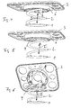
- spring element comprises a lower support surface 1, a spring body 2 and a cover plate 3.
- the spring body 2 has a circular cylindrical portion 4 with external thread 5.
- the cover plate 3 has on its underside a circular cylindrical portion 6 with internal thread 7. External thread 5 and internal thread 7 are reciprocal to each other.
- the winding axis corresponds to the spring axis I.
- the in the 4 to 6 spring body shown also includes a lower support surface 1, a spring body 2 and a cover plate 3.
- the circular cylindrical portion 4 of the spring body 2 is equipped at its outer periphery with bayonet teeth 8.
- the circular cylindrical portion 6 of the cover plate 3 is equipped on its inner circumference with corresponding counter teeth 9, wherein three rings of such counter teeth 9 are arranged one above the other in the direction of the spring axis.
- the spring element shown comprises a lower support surface 1, a spring body 2 and a cover plate 3.
- the two circular cylindrical sections 4 and 6 of the spring body 2 and the cover plate 3 are each provided at their outer periphery with radial pins 10 and 11. These pins 10 and 11 engage in scenes 12 and 13 of a sliding ring 14, which is wrapped around the two circular cylindrical sections 4 and 6 respectively.
- the scenes 12 and 13 are inclined in opposite directions in the direction of the spring axis I.
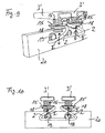
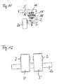
- double edge bearing comprises two lath receptacles 3 'and two coiled helical springs 2, whose turns have a diameter which decreases from bottom to top.
- each a ring 15 rotatably mounted which has an internal thread into which a with the lath receptacle 3 'connected threaded bolt 16 is screwed.
- the thread 17 of the threaded bolt 16 is formed as a trapezoidal thread and extends over its entire height.
- the rotatable ring 15 may for example be mounted captive in a ring 18 which is integrally formed on the upper end of the respective coil spring 2.
- the lower ends of the coil springs 2 are connected to each other and with two pins 19 which are insertable into corresponding receptacles of a spar 20 of a slatted frame.
- Such a height adjustment can also for the spring elements of FIGS. 1 to 8 be used.
Landscapes
- Springs (AREA)
- Mattresses And Other Support Structures For Chairs And Beds (AREA)
Applications Claiming Priority (2)
| Application Number | Priority Date | Filing Date | Title |
|---|---|---|---|
| DE202008002023 | 2008-02-14 | ||
| DE202009000203U DE202009000203U1 (de) | 2008-02-14 | 2009-01-08 | Federelement für eine Federkernmatratze oder eine Untermatratze oder als Randlager für einen Lattenrost |
Publications (2)
| Publication Number | Publication Date |
|---|---|
| EP2090196A2 true EP2090196A2 (fr) | 2009-08-19 |
| EP2090196A3 EP2090196A3 (fr) | 2009-10-21 |
Family
ID=40794812
Family Applications (1)
| Application Number | Title | Priority Date | Filing Date |
|---|---|---|---|
| EP09001987A Withdrawn EP2090196A3 (fr) | 2008-02-14 | 2009-02-12 | Elément de ressort pour un matelas à ressorts ou un sommier ou comme support de rebord pour un caillebotis et support de rebord |
Country Status (2)
| Country | Link |
|---|---|
| EP (1) | EP2090196A3 (fr) |
| DE (1) | DE202009000203U1 (fr) |
Cited By (3)
| Publication number | Priority date | Publication date | Assignee | Title |
|---|---|---|---|---|
| US20110258772A1 (en) * | 2008-09-30 | 2011-10-27 | Frank Verschuere | Bed system |
| WO2021073588A1 (fr) * | 2019-10-17 | 2021-04-22 | 厦门新技术集成有限公司 | Module élastique pour meuble et coussin élastique |
| WO2024188184A1 (fr) * | 2023-03-10 | 2024-09-19 | 厦门新技术集成有限公司 | Module élastique de ressort multicouche, et tampon élastique associé |
Citations (1)
| Publication number | Priority date | Publication date | Assignee | Title |
|---|---|---|---|---|
| DE9107386U1 (de) | 1991-06-14 | 1991-12-05 | Dunlop GmbH, 6450 Hanau | Lattenrost |
Family Cites Families (4)
| Publication number | Priority date | Publication date | Assignee | Title |
|---|---|---|---|---|
| US2630585A (en) * | 1950-07-03 | 1953-03-10 | Clyde B Reese | Adjustable bedspring |
| US3252170A (en) * | 1963-08-08 | 1966-05-24 | James R Frye | Variable firmness mattress |
| FR2824246A1 (fr) * | 2001-05-02 | 2002-11-08 | Tournadre Sa Standard Gum | Dispositif de suspension pour sommier du type multi-elements |
| FR2913322B1 (fr) * | 2007-03-07 | 2009-06-05 | Delahousse Et Fils Sa | Dispositif de reglage du niveau vertical d'un element support de type latte ou plateau pour sommier ou siege |
-
2009
- 2009-01-08 DE DE202009000203U patent/DE202009000203U1/de not_active Expired - Lifetime
- 2009-02-12 EP EP09001987A patent/EP2090196A3/fr not_active Withdrawn
Patent Citations (1)
| Publication number | Priority date | Publication date | Assignee | Title |
|---|---|---|---|---|
| DE9107386U1 (de) | 1991-06-14 | 1991-12-05 | Dunlop GmbH, 6450 Hanau | Lattenrost |
Cited By (4)
| Publication number | Priority date | Publication date | Assignee | Title |
|---|---|---|---|---|
| US20110258772A1 (en) * | 2008-09-30 | 2011-10-27 | Frank Verschuere | Bed system |
| US8918928B2 (en) * | 2008-09-30 | 2014-12-30 | Ls Bedding | Adjustable bed system |
| WO2021073588A1 (fr) * | 2019-10-17 | 2021-04-22 | 厦门新技术集成有限公司 | Module élastique pour meuble et coussin élastique |
| WO2024188184A1 (fr) * | 2023-03-10 | 2024-09-19 | 厦门新技术集成有限公司 | Module élastique de ressort multicouche, et tampon élastique associé |
Also Published As
| Publication number | Publication date |
|---|---|
| EP2090196A3 (fr) | 2009-10-21 |
| DE202009000203U1 (de) | 2009-06-25 |
Similar Documents
| Publication | Publication Date | Title |
|---|---|---|
| DE2732654C3 (de) | Gelenkbeschlag für Leiteiteile | |
| DE69033674T2 (de) | Kunststoffrahmensystem mit dreieckigem Stützpfosten | |
| DE20300248U1 (de) | Federelement für Betten | |
| DE1967120B1 (de) | Lagergestell | |
| DE3710838A1 (de) | Bajonettverschluss | |
| EP1335148B1 (fr) | Corps de soutien, en particulier pour le support élastique d'un meuble d'assise ou de couchage | |
| DE69209098T2 (de) | Treppengeländer | |
| DE2517149A1 (de) | Universell verwendbare strebe fuer eckenverbindungen | |
| DE2452127C3 (de) | Wickelträger mit parallel zu seiner Achse verlaufenden Tragelementen | |
| DE7821666U1 (de) | Speicher- und abgabevorrichtung fuer gestapelte gegenstaende | |
| EP2090196A2 (fr) | Elément de ressort pour un matelas à ressorts ou un sommier ou comme support de rebord pour un caillebotis et support de rebord | |
| DE3436358A1 (de) | Klapp-beschlag | |
| DE2758357A1 (de) | Speicher- und ausgabevorrichtung fuer gestapelte gegenstaende | |
| DE112009004068T5 (de) | Höheneinstellvorrichtung | |
| WO2004085782A1 (fr) | Dispositif de fermeture d'une porte | |
| DE19528901A1 (de) | Höhenverstellbarer Fuß für Küchengeräte oder Möbel | |
| EP1900310A2 (fr) | Elément à ressort pour le support élastique d'un meuble d'assise ou de couchage | |
| DE9109153U1 (de) | Beleuchtungsvorrichtung | |
| DE29610021U1 (de) | Sperrscheibe zum Sichern von Teilen an einer Welle | |
| DE2850049A1 (de) | Naehfuss fuer naehmaschinen | |
| DE19511176C2 (de) | Vorrichtung zur Verstellung der Höhe und/oder Neigung der Tischplatte eines Tisches | |
| DE102018126293A1 (de) | Lattenrost | |
| DE69303216T2 (de) | Tischbeinanordnung | |
| DE3828321A1 (de) | Sitzmoebel mit drehbarem sitz, der automatisch in eine vorgegebene grundstellung einschwenkt | |
| EP0394733B1 (fr) | Dispositif de positionnement pour un support de tête ou de pied |
Legal Events
| Date | Code | Title | Description |
|---|---|---|---|
| PUAI | Public reference made under article 153(3) epc to a published international application that has entered the european phase |
Free format text: ORIGINAL CODE: 0009012 |
|
| AK | Designated contracting states |
Kind code of ref document: A2 Designated state(s): AT BE BG CH CY CZ DE DK EE ES FI FR GB GR HR HU IE IS IT LI LT LU LV MC MK MT NL NO PL PT RO SE SI SK TR |
|
| AX | Request for extension of the european patent |
Extension state: AL BA RS |
|
| PUAL | Search report despatched |
Free format text: ORIGINAL CODE: 0009013 |
|
| AK | Designated contracting states |
Kind code of ref document: A3 Designated state(s): AT BE BG CH CY CZ DE DK EE ES FI FR GB GR HR HU IE IS IT LI LT LU LV MC MK MT NL NO PL PT RO SE SI SK TR |
|
| AX | Request for extension of the european patent |
Extension state: AL BA RS |
|
| 17P | Request for examination filed |
Effective date: 20100421 |
|
| AKX | Designation fees paid |
Designated state(s): AT BE BG CH CY CZ DE DK EE ES FI FR GB GR HR HU IE IS IT LI LT LU LV MC MK MT NL NO PL PT RO SE SI SK TR |
|
| 17Q | First examination report despatched |
Effective date: 20100602 |
|
| STAA | Information on the status of an ep patent application or granted ep patent |
Free format text: STATUS: THE APPLICATION IS DEEMED TO BE WITHDRAWN |
|
| 18D | Application deemed to be withdrawn |
Effective date: 20120901 |