EP2090196A2 - Spring element for a spring core mattress or an under mattress or edge holder for a slated frame - Google Patents
Spring element for a spring core mattress or an under mattress or edge holder for a slated frame Download PDFInfo
- Publication number
- EP2090196A2 EP2090196A2 EP09001987A EP09001987A EP2090196A2 EP 2090196 A2 EP2090196 A2 EP 2090196A2 EP 09001987 A EP09001987 A EP 09001987A EP 09001987 A EP09001987 A EP 09001987A EP 2090196 A2 EP2090196 A2 EP 2090196A2
- Authority
- EP
- European Patent Office
- Prior art keywords
- spring
- spring element
- cover plate
- circular cylindrical
- element according
- Prior art date
- Legal status (The legal status is an assumption and is not a legal conclusion. Google has not performed a legal analysis and makes no representation as to the accuracy of the status listed.)
- Withdrawn
Links
Images


Classifications
-
- A—HUMAN NECESSITIES
- A47—FURNITURE; DOMESTIC ARTICLES OR APPLIANCES; COFFEE MILLS; SPICE MILLS; SUCTION CLEANERS IN GENERAL
- A47C—CHAIRS; SOFAS; BEDS
- A47C23/00—Spring mattresses with rigid frame or forming part of the bedstead, e.g. box springs; Divan bases; Slatted bed bases
- A47C23/002—Spring mattresses with rigid frame or forming part of the bedstead, e.g. box springs; Divan bases; Slatted bed bases with separate resilient support elements, e.g. elastomeric springs arranged in a two-dimensional matrix pattern
-
- A—HUMAN NECESSITIES
- A47—FURNITURE; DOMESTIC ARTICLES OR APPLIANCES; COFFEE MILLS; SPICE MILLS; SUCTION CLEANERS IN GENERAL
- A47C—CHAIRS; SOFAS; BEDS
- A47C23/00—Spring mattresses with rigid frame or forming part of the bedstead, e.g. box springs; Divan bases; Slatted bed bases
- A47C23/06—Spring mattresses with rigid frame or forming part of the bedstead, e.g. box springs; Divan bases; Slatted bed bases using wooden springs, e.g. of slat type ; Slatted bed bases
- A47C23/062—Slat supports
- A47C23/063—Slat supports by elastic means, e.g. coil springs
- A47C23/064—Slat supports by elastic means, e.g. coil springs by elastomeric springs
-
- A—HUMAN NECESSITIES
- A47—FURNITURE; DOMESTIC ARTICLES OR APPLIANCES; COFFEE MILLS; SPICE MILLS; SUCTION CLEANERS IN GENERAL
- A47C—CHAIRS; SOFAS; BEDS
- A47C23/00—Spring mattresses with rigid frame or forming part of the bedstead, e.g. box springs; Divan bases; Slatted bed bases
- A47C23/06—Spring mattresses with rigid frame or forming part of the bedstead, e.g. box springs; Divan bases; Slatted bed bases using wooden springs, e.g. of slat type ; Slatted bed bases
- A47C23/062—Slat supports
- A47C23/067—Slat supports adjustable, e.g. in height or elasticity
-
- A—HUMAN NECESSITIES
- A47—FURNITURE; DOMESTIC ARTICLES OR APPLIANCES; COFFEE MILLS; SPICE MILLS; SUCTION CLEANERS IN GENERAL
- A47C—CHAIRS; SOFAS; BEDS
- A47C27/00—Spring, stuffed or fluid mattresses or cushions specially adapted for chairs, beds or sofas
- A47C27/04—Spring, stuffed or fluid mattresses or cushions specially adapted for chairs, beds or sofas with spring inlays
- A47C27/06—Spring inlays
- A47C27/065—Spring inlays of special shape
Definitions
- the present invention relates to a spring element for a spring pad or a mattress or as an edge bearing for a slatted base with a lower support member, a spring body and a cover plate and an edge bearing for slats of a slatted frame or support strips with a receptacle for the end of a slat or support bar, a storage , In particular at least one journal, for supporting the edge bearing on a spar of the slatted frame and a resilient connection between the storage and the recording.
- Such spring elements are used for example as part of a lower mattress with a plurality of distributed over at least a portion of the lower mattress, arranged independently of each other such spring element for supporting an upper mattress or as a spring core of a mattress top. In sub-mattresses, they replace the conventional spring strips in the corresponding areas and offer the advantage of a virtually point-elastic support.
- such spring elements are used as edge bearings for a slatted frame. For this purpose, the spring elements on a receptacle for the ends of a bar or a support bar.
- Partial sub-mattresses such spring elements are used with different heights. For this purpose, various spring elements must be made available and kept in stock. The same applies to edge bearings, which are resiliently supported in certain applications against the longitudinal spar of a slatted frame.
- the invention has for its object to reduce the manufacturing cost of under-mattresses and spring mattresses.
- This object is achieved in that a first and a second circular cylindrical portion are present between the cover plate or a slats receiving and spring body and / or between the spring body and lower support member and / or between a first and a second spring body part and that the two circular cylindrical portions around the spring axis against each other rotatable connected to each other or are connectable, wherein on the rotation of the distance between the cover plate or lath receptacle and lower support member of the spring element is variable.
- the spring element Due to the height-adjustable design of the spring element, it is unnecessary to produce spring elements with different heights and to keep in stock.
- the different heights can be achieved by adjusting the spring element, which is particularly low possible on the circular cylindrical connecting portions between the top plate and spring body.
- the two circular cylindrical sections are provided with an inner or a reciprocal outer thread for this purpose.
- an inner or a reciprocal outer thread for this purpose.
- the desired height can be easily adjusted.
- a locking is provided, through which a set height is maintained.
- Another possibility is a kind of bayonet closure, in which at one of the two circular cylindrical sections two or more Sprockets offset in the direction of the spring axis are provided. Depending on which sprocket the counter-teeth present on the other circular-cylindrical section are brought into engagement, the distance between the support surface and the cover plate of the spring element changes.
- the mating teeth are provided according to the inner or outer circumference of the other circular cylindrical portion. Over the circumference, three, four or more teeth and opposing teeth may be provided.
- each of the circular cylindrical sections outwardly directed pins which engage in each case in a backdrop of the two cylindrical sections surrounding link ring.
- the scenes are inclined in the opposite direction in the direction of the spring axis, and the pins of the first circular cylindrical section engage in scenes of a tilt direction, while the pins of the other circular cylindrical section engage in scenes of the other direction of inclination.
- the spring body may be formed as a helical spring.
- a ring may be rotatably mounted at the upper end of the coil spring having an internal thread into which a threaded bolt connected to the cover plate or the lath receptacle is screwed.
- a threaded bolt connected to the cover plate or the lath receptacle is screwed.
- an edge bearing of the type mentioned is provided in which the resilient connection is formed as a helical spring, wherein the diameter of the turns of the helical spring decreases from bottom to top. This results in a good and stable spring action.
- the spring element or the edge bearing are preferably curved arcuately. This results in a uniform deformation of the coil spring.
- the coil spring is preferably formed from material having a circular cross-section. This also results in a uniform, harmonic deformation of the coil spring under load.
- the spring element or edge bearing is also at least partially made of a plastic material.
- Plastic is relatively light and, moreover, often preferred today because it does not respond to electromagnetic fields.
- the preparation can preferably be carried out by injection molding, which is relatively inexpensive and leads to good results.
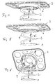
- spring element comprises a lower support surface 1, a spring body 2 and a cover plate 3.
- the spring body 2 has a circular cylindrical portion 4 with external thread 5.
- the cover plate 3 has on its underside a circular cylindrical portion 6 with internal thread 7. External thread 5 and internal thread 7 are reciprocal to each other.
- the winding axis corresponds to the spring axis I.
- the in the 4 to 6 spring body shown also includes a lower support surface 1, a spring body 2 and a cover plate 3.
- the circular cylindrical portion 4 of the spring body 2 is equipped at its outer periphery with bayonet teeth 8.
- the circular cylindrical portion 6 of the cover plate 3 is equipped on its inner circumference with corresponding counter teeth 9, wherein three rings of such counter teeth 9 are arranged one above the other in the direction of the spring axis.
- the spring element shown comprises a lower support surface 1, a spring body 2 and a cover plate 3.
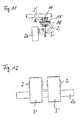
- the two circular cylindrical sections 4 and 6 of the spring body 2 and the cover plate 3 are each provided at their outer periphery with radial pins 10 and 11. These pins 10 and 11 engage in scenes 12 and 13 of a sliding ring 14, which is wrapped around the two circular cylindrical sections 4 and 6 respectively.
- the scenes 12 and 13 are inclined in opposite directions in the direction of the spring axis I.
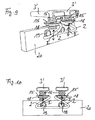
- double edge bearing comprises two lath receptacles 3 'and two coiled helical springs 2, whose turns have a diameter which decreases from bottom to top.
- each a ring 15 rotatably mounted which has an internal thread into which a with the lath receptacle 3 'connected threaded bolt 16 is screwed.
- the thread 17 of the threaded bolt 16 is formed as a trapezoidal thread and extends over its entire height.
- the rotatable ring 15 may for example be mounted captive in a ring 18 which is integrally formed on the upper end of the respective coil spring 2.
- the lower ends of the coil springs 2 are connected to each other and with two pins 19 which are insertable into corresponding receptacles of a spar 20 of a slatted frame.
- Such a height adjustment can also for the spring elements of FIGS. 1 to 8 be used.
Abstract
Description
Die vorliegende Erfindung betrifft ein Federelement für eine Federkemmatratze oder eine Untermatratze oder als Randlager für einen Lattenrost mit einem unteren Stützteil, einem Federkörper und einer Deckplatte sowie ein Randlager für Latten eines Lattenrostes oder Trägerleisten mit einer Aufnahme für das Ende einer Latte oder Trägerleiste, einer Lagerung, insbesondere mindestens einem Lagerzapfen, zum Abstützen des Randlagers an einem Holm des Lattenrostes und einer federnden Verbindung zwischen der Lagerung und der Aufnahme.The present invention relates to a spring element for a spring pad or a mattress or as an edge bearing for a slatted base with a lower support member, a spring body and a cover plate and an edge bearing for slats of a slatted frame or support strips with a receptacle for the end of a slat or support bar, a storage , In particular at least one journal, for supporting the edge bearing on a spar of the slatted frame and a resilient connection between the storage and the recording.
Derartige Federelemente werden beispielsweise als Teil einer Untermatratze mit einer Vielzahl von über mindestens einen Teil der Untermatratze verteilt angeordneten, voneinander unabhängigen derartigen Federelement zur Abstützung einer Obermatratze oder als Federkern einer Obermatratze eingesetzt. In Untermatratzen ersetzen sie in den entsprechenden Bereichen die herkömmlichen Federleisten und bringen den Vorteil einer quasi punktelastischen Abstützung mit sich. Außerdem werden derartige Federelemente als Randlager für einen Lattenrost eingesetzt. Hierfür weisen die Federelemente eine Aufnahme für die Enden einer Latte oder einer Trägerleiste auf.Such spring elements are used for example as part of a lower mattress with a plurality of distributed over at least a portion of the lower mattress, arranged independently of each other such spring element for supporting an upper mattress or as a spring core of a mattress top. In sub-mattresses, they replace the conventional spring strips in the corresponding areas and offer the advantage of a virtually point-elastic support. In addition, such spring elements are used as edge bearings for a slatted frame. For this purpose, the spring elements on a receptacle for the ends of a bar or a support bar.
Teilweise werden in Untermatratzen derartige Federelemente mit unterschiedlicher Höhe eingesetzt. Hierfür müssen verschiedene Federelemente zur Verfügung gestellt und vorrätig gehalten werden. Dasselbe gilt für Randlager, die in bestimmten Anwendungsfällen federnd gegenüber dem Längsholm eines Lattenrostes abgestützt sind.Partial sub-mattresses such spring elements are used with different heights. For this purpose, various spring elements must be made available and kept in stock. The same applies to edge bearings, which are resiliently supported in certain applications against the longitudinal spar of a slatted frame.
Der Erfindung liegt die Aufgabe zugrunde, die Herstellungskosten von Untermatratzen und Federkernmatratzen zu verringern.The invention has for its object to reduce the manufacturing cost of under-mattresses and spring mattresses.
Diese Aufgabe wird dadurch gelöst, dass zwischen Deckplatte oder einer Lattenaufnahme und Federkörper und/oder zwischen Federkörper und unterem Stützteil und/oder zwischen einem ersten und einem zweiten Federkörperteil ein erster und ein zweiter kreiszylindrischer Abschnitt vorhanden sind und dass die beiden kreiszylindrischen Abschnitte um die Federachse gegeneinander verdrehbar miteinander verbunden oder verbindbar sind, wobei über die Verdrehung der Abstand zwischen Deckplatte oder Lattenaufnahme und unterem Stützteil des Federelementes veränderbar ist.This object is achieved in that a first and a second circular cylindrical portion are present between the cover plate or a slats receiving and spring body and / or between the spring body and lower support member and / or between a first and a second spring body part and that the two circular cylindrical portions around the spring axis against each other rotatable connected to each other or are connectable, wherein on the rotation of the distance between the cover plate or lath receptacle and lower support member of the spring element is variable.
Durch die höhenverstellbare Ausgestaltung des Federelementes ist es entbehrlich, Federelemente mit unterschiedlicher Höhe herzustellen und vorrätig zu halten. Die unterschiedlichen Höhen können durch Verstellen des Federelementes erreicht werden, was über die kreiszylindrischen Verbindungsabschnitte zwischen Kopfplatte und Federkörper besonders günstig möglich ist.Due to the height-adjustable design of the spring element, it is unnecessary to produce spring elements with different heights and to keep in stock. The different heights can be achieved by adjusting the spring element, which is particularly low possible on the circular cylindrical connecting portions between the top plate and spring body.
Nach einer Ausgestaltung der Erfindung sind die beiden kreiszylindrischen Abschnitte mit einem Innen- bzw. einem hierzu reziproken Außengewinde versehen. Durch mehr oder weniger weites Eindrehen des Innengewindes in das Außengewinde kann die gewünschte Höhe in einfacher Weise eingestellt werden. Bevorzugt ist dabei eine Verrastung vorgesehen, durch welche eine eingestellte Höhe erhalten bleibt.According to one embodiment of the invention, the two circular cylindrical sections are provided with an inner or a reciprocal outer thread for this purpose. By more or less wide screwing the internal thread in the external thread, the desired height can be easily adjusted. Preferably, a locking is provided, through which a set height is maintained.
Eine andere Möglichkeit besteht in einer Art Bajonettverschluss, bei welchem an einem der beiden kreiszylindrischen Abschnitte zwei oder mehr in Richtung der Federachse versetzte Zahnkränze vorgesehen sind. Je nachdem, mit welchem Zahnkranz die an dem anderen kreiszylindrischen Abschnitt vorhandenen Gegenzähne in Eingriff gebracht werden, verändert sich der Abstand zwischen Stützfläche und Deckplatte des Federelementes. Es können zwei, drei oder mehr Kränze übereinander angeordnet sein, wobei diese als Innenkranz oder als Außenkranz vorgesehen sein können. Die Gegenzähne sind entsprechend am Innen- oder Außenumfang des anderen kreiszylindrischen Abschnitts vorgesehen. Über den Umfang können drei, vier oder mehr Zähne und Gegenzähne vorgesehen sein.Another possibility is a kind of bayonet closure, in which at one of the two circular cylindrical sections two or more Sprockets offset in the direction of the spring axis are provided. Depending on which sprocket the counter-teeth present on the other circular-cylindrical section are brought into engagement, the distance between the support surface and the cover plate of the spring element changes. There may be two, three or more wreaths arranged one above the other, which may be provided as an inner rim or as an outer rim. The mating teeth are provided according to the inner or outer circumference of the other circular cylindrical portion. Over the circumference, three, four or more teeth and opposing teeth may be provided.
Eine weitere Möglichkeit besteht darin, an den kreiszylindrischen Abschnitten jeweils nach außen gerichtete Stifte vorzusehen, die jeweils in eine Kulisse eines die beiden zylindrischen Abschnitte umschließenden Kulissenrings eingreifen. Die Kulissen sind dabei in Richtung der Federachse gegensinnig geneigt, und die Stifte des ersten kreiszylindrischen Abschnitts greifen in Kulissen der einen Neigungsrichtung, während die Stifte des anderen kreiszylindrischen Abschnitts in Kulissen der anderen Neigungsrichtung greifen. Durch Verdrehen des Kulissenrings ändert sich so der Abstand zwischen Stützfläche und Deckplatte des Federelements.Another possibility is to provide each of the circular cylindrical sections outwardly directed pins which engage in each case in a backdrop of the two cylindrical sections surrounding link ring. The scenes are inclined in the opposite direction in the direction of the spring axis, and the pins of the first circular cylindrical section engage in scenes of a tilt direction, while the pins of the other circular cylindrical section engage in scenes of the other direction of inclination. By rotating the slide ring so the distance between the support surface and cover plate of the spring element changes.
Nach einer Ausgestaltung der Erfindung kann der Federkörper als Wendelfeder ausgebildet sein. In diesem Fall kann am oberen Ende der Wendelfeder ein Ring drehbar gelagert sein, der ein Innengewinde aufweist, in welches ein mit der Deckplatte oder der Lattenaufnahme verbundener Gewindebolzen eingedreht ist. Durch Verdrehen des Rings kann der Gewindebolzen ein- und ausgedreht werden. Entsprechend der Gewindeausbildung hebt oder senkt sich dadurch die Deckplatte oder Lattenaufnahme. Bei paarweise angeordneten Randlagern mit zwei derartigen Wendelfedern kann jedes Randlager für sich separat in der Höhe eingestellt werden.According to one embodiment of the invention, the spring body may be formed as a helical spring. In this case, a ring may be rotatably mounted at the upper end of the coil spring having an internal thread into which a threaded bolt connected to the cover plate or the lath receptacle is screwed. By turning the ring of the threaded bolt can be turned on and turned off. As a result of the thread formation, this raises or lowers the cover plate or lath receptacle. For paired edge bearings with two such coil springs Each edge bearing can be adjusted separately in height.
Nach einer unabhängigen Ausgestaltung der Erfindung ist ein Randlager der eingangs genannten Art vorgesehen, bei welchem die federnde Verbindung als Wendelfeder ausgebildet ist, wobei der Durchmesser der Windungen der Wendelfeder von unten nach oben abnimmt. Dadurch ergibt sich eine gute und stabile Federwirkung.According to an independent embodiment of the invention, an edge bearing of the type mentioned is provided in which the resilient connection is formed as a helical spring, wherein the diameter of the turns of the helical spring decreases from bottom to top. This results in a good and stable spring action.
Das Federelement oder das Randlager sind bevorzugt bogenförmig gewendelt. Dadurch ergibt sich eine gleichmäßige Verformung der Wendelfeder.The spring element or the edge bearing are preferably curved arcuately. This results in a uniform deformation of the coil spring.
Des weiteren ist die Wendelfeder bevorzugt aus Material mit kreisförmigem Querschnitt gebildet. Auch hierdurch ergibt sich eine gleichmäßige, harmonische Verformung der Wendelfeder bei Belastung.Furthermore, the coil spring is preferably formed from material having a circular cross-section. This also results in a uniform, harmonic deformation of the coil spring under load.
Das Federelement oder Randlager ist außerdem zumindest teilweise aus einem Kunststoffmaterial hergestellt. Kunststoff ist verhältnismäßig leicht und außerdem heute oftmals bevorzugt, da es nicht auf elektromagnetische Felder reagiert. Die Herstellung kann bevorzugt im Spritzgussverfahren erfolgen, was verhältnismäßig kostengünstig ist und zu guten Ergebnissen führt.The spring element or edge bearing is also at least partially made of a plastic material. Plastic is relatively light and, moreover, often preferred today because it does not respond to electromagnetic fields. The preparation can preferably be carried out by injection molding, which is relatively inexpensive and leads to good results.
Ausführungsbeispiele der Erfindung sind in den Zeichnungen dargestellt und werden nachfolgend beschrieben. Es zeigen, jeweils in schematischer Darstellung,
-
Fig. 1 bis 3 ein Federelement mit Gewindeverbindung zwischen Deckplatte und Federkörper, -
Fig. 4 bis 6 ein Federelement mit bajonettartiger Verbindung zwischen Deckplatte und Federkörper, -
Fig. 7 und 8 ein Federelement mit Kulissenverbindung zwischen Deckplatte und Federkörper, und -
Fig. 9 bis 12 ein Doppelrandlager mit zwei Wendelfedern.
-
Fig. 1 to 3 a spring element with threaded connection between cover plate and spring body, -
4 to 6 a spring element with a bayonet-type connection between cover plate and spring body, -
FIGS. 7 and 8 a spring element with link connection between cover plate and spring body, and -
Fig. 9 to 12 a double edge bearing with two coil springs.
Das in den
Durch Eindrehen des Außengewindes 5 in das Innengewinde 7 werden Deckplatte 3 und Federkörper 2 miteinander verbunden. Über die Eindrehtiefe kann dabei die Höhe des Federelementes eingestellt werden. Über nicht dargestellte Verrastungen kann eine eingestellte Höhe gegen Verändern festgelegt werden.By screwing the external thread 5 in the
Der in den
Auch das in den
Weitere Varianten zur Höhenverstellung mit kreiszylindrischen Abschnitten 4 und 6 sind ebenfalls möglich. Wichtig ist, dass die Höhenverstellung durch einfaches Verdrehen möglich ist. Dementsprechend könnte eine entsprechende Drehverbindung auch zwischen Federkörper 2 und Stützfläche 1 vorgesehen sein. Ebenso könnte der Federkörper zweiteilig ausgebildet sein, wobei die beiden Teile über eine entsprechende Drehverbindung mit kreiszylindrischen Abschnitten miteinander verbunden sind. In allen Fällen ergibt sich eine kostengünstige Höhenverstellung für derartige Federelemente.Other variants for height adjustment with circular
Das in den
Wie man erkennt, können die Aufnahmen 3' durch Verdrehen des jeweiligen Rings 15 in der Höhe verstellt werden, da der in den Ring 15 eingedrehte Gewindezapfen 16 je nach Drehrichtung angehoben oder abgesenkt wird. Dabei können die beiden Aufnahmen 3' unabhängig voneinander eingestellt werden. Eine derartige Höheneinstellung kann auch für die Federelemente der
Claims (12)
dadurch gekennzeichnet,
dass zwischen Deckplatte (3) oder Lattenaufnahme (3') und Federkörper (2) und/oder zwischen Federkörper (2) und unterem Stützteil (1) und/oder zwischen einem ersten und einem zweiten Federkörperteil ein erster und ein zweiter kreiszylindrischer Abschnitt (4, 6) vorhanden sind und dass die beiden kreiszylindrischen Abschnitte (4, 6) um die Federachse (I) gegeneinander verdrehbar miteinander verbunden oder verbindbar sind, wobei über die Verdrehung der Abstand zwischen Deckplatte (3) oder Lattenaufnahme (3') und unterem Stützteil (1) des Federelementes veränderbar ist.Spring element for a spring mattress or a lower mattress or as an edge bearing for a slatted frame with a lower support part (1), a spring body (2) and a cover plate (3) or a slat reception (3 '),
characterized,
that between the cover plate (3) or bar holder (3 ') and the spring body (2) and / or between the spring body (2) and the lower support part (1) and / or between a first and a second spring body portion, a first and a second circular cylindrical portion (4 , 6) are present and that the two circular cylindrical sections (4, 6) around the spring axis (I) against each other rotatably connected or connectable, wherein on the rotation of the distance between the cover plate (3) or lath receptacle (3 ') and lower support member (1) of the spring element is variable.
dadurch gekennzeichnet,
dass die Verbindung durch ein Innengewinde (7) und ein reziprokes Außengewinde (5) gebildet ist.Spring element according to claim 1,
characterized,
in that the connection is formed by an internal thread (7) and a reciprocal external thread (5).
dadurch gekennzeichnet,
dass die Verbindung durch eine Art Bajonettverschluss (8, 9) mit zwei oder mehr in Federrichtung versetzt angeordneten Ebenen gebildet ist.Spring element according to claim 1,
characterized,
is formed that the connection by a kind of bayonet catch (8, 9) with two or more offset in the spring direction planes arranged.
dadurch gekennzeichnet,
dass die Verbindung durch einen Kulissenring (14) mit in Richtung der Federachse gegensinnig geneigten Kulissen (12, 13) und in die Kulissen eingreifende radiale Stifte (10, 11) an den Außenumfängen der beiden kreiszylindrischen Abschnitte (4, 6) gebildet ist.Spring element according to claim 1,
characterized,
in that the connection is formed by a slotted ring (14) with oppositely inclined guideways (12, 13) in the direction of the spring axis and radial pins (10, 11) engaging in the slits on the outer peripheries of the two circular cylindrical sections (4, 6).
dadurch gekennzeichnet,
dass an der Oberseite des Federkörpers (2) ein erster kreiszylindrischer Abschnitt (4) und an der Unterseite der Deckplatte (3) ein zweiter kreiszylindrischer Abschnitt (6) vorhanden ist und dass Kopfplatte (3) und Federkörper (2) über die beiden kreiszylindrischen Abschnitte (4, 6) um die Federachse (I) gegeneinander verdrehbar miteinander verbunden oder verbindbar sind, wobei über die Verdrehung der Abstand zwischen Kopfplatte (3) und Stützfläche (1) des Federelementes veränderbar ist.Spring element according to one of the preceding claims,
characterized,
that on the upper side of the spring body (2) is a first circular cylindrical portion (4) and on the underside of the cover plate (3), a second circular cylindrical portion (6) is present and that the head plate (3) and the spring body (2) via the two circular cylindrical portions (4, 6) around the spring axis (I) against each other rotatably connected or connectable to each other, wherein on the rotation of the distance between the top plate (3) and support surface (1) of the spring element is variable.
dadurch gekennzeichnet,
dass zwischen den beiden kreiszylindrischen Abschnitten (4, 6) eine Verrastung vorgesehen ist, über welche eine eingestellte Höhe gesichert ist.Spring element according to one of the preceding claims,
characterized,
that between the two circular-cylindrical sections (4, 6) is provided a latching, via which a set height is secured.
dadurch gekennzeichnet,
dass der Federkörper (2) als Wendelfeder ausgebildet ist.Spring element according to one of the preceding claims,
characterized,
that the spring body (2) is designed as a helical spring.
dadurch gekennzeichnet,
dass am oberen Ende der Wendelfeder (2) ein Ring (15) drehbar gelagert ist, der ein Innengewinde aufweist, in welches ein mit der Deckplatte (3) oder der Lattenaufnahme (3') verbundener Gewindebolzen (16) eingedreht ist.Spring element according to claim 7,
characterized,
that at the upper end of the coil spring (2) a ring (15) is rotatably mounted, which has an internal thread into which a with the cover plate (3) or the lath receptacle (3 ') connected threaded bolt (16) is screwed.
dass die federnde Verbindung als Wendelfeder (2) ausgebildet ist, wobei der Durchmesser der Windungen der Wendelfeder (2) von unten nach oben abnimmt.Edge storage for slats of a slatted frame or support rails with a receptacle (3 ') for the end of a slat or support bar, a storage, in particular at least one bearing pin (19), for supporting the edge bearing on a spar (20) of the slatted frame and a resilient connection ( 2) between the bearing (19) and the receptacle (3 '), characterized
that the resilient connection is formed as a helical spring (2), wherein the diameter of the turns of the helical spring (2) decreases from bottom to top.
dadurch gekennzeichnet,
dass die Wendelfeder (2) bogenförmig gewendelt ist.Spring element or edge bearing according to one of the preceding claims,
characterized,
that the spiral spring (2) is curved in an arc.
dadurch gekennzeichnet,
dass die Wendelfeder (2) aus Material mit kreisförmigem Querschnitt gebildet ist.Spring element or edge bearing according to one of the preceding claims,
characterized,
that the helical spring (2) is formed of material having a circular cross-section.
dadurch gekennzeichnet,
dass es zumindest teilweise aus einem Kunststoffmaterial und bevorzugt mittels eines Spritzgussverfahrens hergestellt ist.Spring element or edge bearing according to one of the preceding claims,
characterized,
that it is at least partially made of a plastic material and preferably by means of an injection molding process.
Applications Claiming Priority (2)
| Application Number | Priority Date | Filing Date | Title |
|---|---|---|---|
| DE202008002023 | 2008-02-14 | ||
| DE202009000203U DE202009000203U1 (en) | 2008-02-14 | 2009-01-08 | Spring element for a spring mattress or a mattress or as edge storage for a slatted frame |
Publications (2)
| Publication Number | Publication Date |
|---|---|
| EP2090196A2 true EP2090196A2 (en) | 2009-08-19 |
| EP2090196A3 EP2090196A3 (en) | 2009-10-21 |
Family
ID=40794812
Family Applications (1)
| Application Number | Title | Priority Date | Filing Date |
|---|---|---|---|
| EP09001987A Withdrawn EP2090196A3 (en) | 2008-02-14 | 2009-02-12 | Spring element for a spring core mattress or an under mattress or edge holder for a slated frame |
Country Status (2)
| Country | Link |
|---|---|
| EP (1) | EP2090196A3 (en) |
| DE (1) | DE202009000203U1 (en) |
Cited By (2)
| Publication number | Priority date | Publication date | Assignee | Title |
|---|---|---|---|---|
| US20110258772A1 (en) * | 2008-09-30 | 2011-10-27 | Frank Verschuere | Bed system |
| WO2021073588A1 (en) * | 2019-10-17 | 2021-04-22 | 厦门新技术集成有限公司 | Elastic module for furniture and elastic cushion |
Citations (1)
| Publication number | Priority date | Publication date | Assignee | Title |
|---|---|---|---|---|
| DE9107386U1 (en) | 1991-06-14 | 1991-12-05 | Dunlop Gmbh, 6450 Hanau, De |
Family Cites Families (4)
| Publication number | Priority date | Publication date | Assignee | Title |
|---|---|---|---|---|
| US2630585A (en) * | 1950-07-03 | 1953-03-10 | Clyde B Reese | Adjustable bedspring |
| US3252170A (en) * | 1963-08-08 | 1966-05-24 | James R Frye | Variable firmness mattress |
| FR2824246A1 (en) * | 2001-05-02 | 2002-11-08 | Tournadre Sa Standard Gum | MULTI-ELEMENT-TYPE SUSPENSION SUSPENSION DEVICE |
| FR2913322B1 (en) * | 2007-03-07 | 2009-06-05 | Delahousse Et Fils Sa | DEVICE FOR ADJUSTING THE VERTICAL LEVEL OF A LATTE-TYPE SUPPORTING ELEMENT OR PLATE FOR SOMMIER OR SEAT |
-
2009
- 2009-01-08 DE DE202009000203U patent/DE202009000203U1/en not_active Expired - Lifetime
- 2009-02-12 EP EP09001987A patent/EP2090196A3/en not_active Withdrawn
Patent Citations (1)
| Publication number | Priority date | Publication date | Assignee | Title |
|---|---|---|---|---|
| DE9107386U1 (en) | 1991-06-14 | 1991-12-05 | Dunlop Gmbh, 6450 Hanau, De |
Cited By (3)
| Publication number | Priority date | Publication date | Assignee | Title |
|---|---|---|---|---|
| US20110258772A1 (en) * | 2008-09-30 | 2011-10-27 | Frank Verschuere | Bed system |
| US8918928B2 (en) * | 2008-09-30 | 2014-12-30 | Ls Bedding | Adjustable bed system |
| WO2021073588A1 (en) * | 2019-10-17 | 2021-04-22 | 厦门新技术集成有限公司 | Elastic module for furniture and elastic cushion |
Also Published As
| Publication number | Publication date |
|---|---|
| EP2090196A3 (en) | 2009-10-21 |
| DE202009000203U1 (en) | 2009-06-25 |
Similar Documents
| Publication | Publication Date | Title |
|---|---|---|
| DE2732654C3 (en) | Articulated fitting for control panels | |
| DE1967120B1 (en) | Storage rack | |
| DE3710838A1 (en) | BAYONET CLOSURE | |
| DE2435147C3 (en) | Frame made from partially bent profile rods | |
| DE3921369C2 (en) | Tubular support body for cartridge-shaped filter elements | |
| EP1335148B1 (en) | Supporting body, in particular for elastically supporting a sitting or lying furniture | |
| DE2517149A1 (en) | UNIVERSALLY APPLICABLE STRUT FOR CORNER CONNECTIONS | |
| DE2452127C3 (en) | Winding carrier with support elements running parallel to its axis | |
| DE7821666U1 (en) | STORAGE AND DISPENSER DEVICE FOR STACKED ITEMS | |
| DE3436358A1 (en) | FOLDING FITTING | |
| EP0000499B1 (en) | Hinge furnishing for ladder elements | |
| DE2758357A1 (en) | STORAGE AND DISPENSER DEVICE FOR STACKED ITEMS | |
| EP2090196A2 (en) | Spring element for a spring core mattress or an under mattress or edge holder for a slated frame | |
| WO2008125318A2 (en) | Adjustable bar guide | |
| DE2437172A1 (en) | ADJUSTMENT DEVICE FOR SEATS | |
| DE112009004068T5 (en) | height adjuster | |
| EP1613828A1 (en) | Device for closing a door | |
| EP1900310A2 (en) | Spring element for elastically supporting a sitting or lying furniture | |
| EP2412278A1 (en) | Support element of a seat or bed furniture spring support | |
| DE2850049A1 (en) | NEAR FOOT FOR SEWING MACHINES | |
| DE19511176C2 (en) | Device for adjusting the height and / or inclination of the table top of a table | |
| EP0702914A1 (en) | Furniture drawer element, for drawers or the like | |
| DE3828321A1 (en) | A piece of seating furniture with a rotatable seat which automatically pivots into a preset starting position | |
| EP0394733B1 (en) | Head or foot support positioning device | |
| DE2816757B2 (en) | Sick bed with a table at the head of the bed |
Legal Events
| Date | Code | Title | Description |
|---|---|---|---|
| PUAI | Public reference made under article 153(3) epc to a published international application that has entered the european phase |
Free format text: ORIGINAL CODE: 0009012 |
|
| AK | Designated contracting states |
Kind code of ref document: A2 Designated state(s): AT BE BG CH CY CZ DE DK EE ES FI FR GB GR HR HU IE IS IT LI LT LU LV MC MK MT NL NO PL PT RO SE SI SK TR |
|
| AX | Request for extension of the european patent |
Extension state: AL BA RS |
|
| PUAL | Search report despatched |
Free format text: ORIGINAL CODE: 0009013 |
|
| AK | Designated contracting states |
Kind code of ref document: A3 Designated state(s): AT BE BG CH CY CZ DE DK EE ES FI FR GB GR HR HU IE IS IT LI LT LU LV MC MK MT NL NO PL PT RO SE SI SK TR |
|
| AX | Request for extension of the european patent |
Extension state: AL BA RS |
|
| 17P | Request for examination filed |
Effective date: 20100421 |
|
| AKX | Designation fees paid |
Designated state(s): AT BE BG CH CY CZ DE DK EE ES FI FR GB GR HR HU IE IS IT LI LT LU LV MC MK MT NL NO PL PT RO SE SI SK TR |
|
| 17Q | First examination report despatched |
Effective date: 20100602 |
|
| STAA | Information on the status of an ep patent application or granted ep patent |
Free format text: STATUS: THE APPLICATION IS DEEMED TO BE WITHDRAWN |
|
| 18D | Application deemed to be withdrawn |
Effective date: 20120901 |