EP2090150A2 - Mähvorrichtung - Google Patents
Mähvorrichtung Download PDFInfo
- Publication number
- EP2090150A2 EP2090150A2 EP09075069A EP09075069A EP2090150A2 EP 2090150 A2 EP2090150 A2 EP 2090150A2 EP 09075069 A EP09075069 A EP 09075069A EP 09075069 A EP09075069 A EP 09075069A EP 2090150 A2 EP2090150 A2 EP 2090150A2
- Authority
- EP
- European Patent Office
- Prior art keywords
- blade
- rotor
- rotation
- rotation axis
- mowing device
- Prior art date
- Legal status (The legal status is an assumption and is not a legal conclusion. Google has not performed a legal analysis and makes no representation as to the accuracy of the status listed.)
- Granted
Links
- 238000010008 shearing Methods 0.000 claims description 21
- 230000000694 effects Effects 0.000 claims description 5
- 238000000034 method Methods 0.000 claims description 4
- 230000005484 gravity Effects 0.000 claims description 2
- 241000196324 Embryophyta Species 0.000 description 10
- 230000000712 assembly Effects 0.000 description 6
- 238000000429 assembly Methods 0.000 description 6
- 230000001174 ascending effect Effects 0.000 description 2
- 238000006073 displacement reaction Methods 0.000 description 2
- 244000025254 Cannabis sativa Species 0.000 description 1
- 230000005540 biological transmission Effects 0.000 description 1
- 238000007689 inspection Methods 0.000 description 1
- 230000002452 interceptive effect Effects 0.000 description 1
- 238000005461 lubrication Methods 0.000 description 1
- 239000004575 stone Substances 0.000 description 1
- 239000000725 suspension Substances 0.000 description 1
Images


Classifications
-
- A—HUMAN NECESSITIES
- A01—AGRICULTURE; FORESTRY; ANIMAL HUSBANDRY; HUNTING; TRAPPING; FISHING
- A01D—HARVESTING; MOWING
- A01D34/00—Mowers; Mowing apparatus of harvesters
- A01D34/01—Mowers; Mowing apparatus of harvesters characterised by features relating to the type of cutting apparatus
- A01D34/412—Mowers; Mowing apparatus of harvesters characterised by features relating to the type of cutting apparatus having rotating cutters
- A01D34/63—Mowers; Mowing apparatus of harvesters characterised by features relating to the type of cutting apparatus having rotating cutters having cutters rotating about a vertical axis
- A01D34/73—Cutting apparatus
- A01D34/733—Cutting-blade mounting means
-
- A—HUMAN NECESSITIES
- A01—AGRICULTURE; FORESTRY; ANIMAL HUSBANDRY; HUNTING; TRAPPING; FISHING
- A01D—HARVESTING; MOWING
- A01D34/00—Mowers; Mowing apparatus of harvesters
- A01D34/01—Mowers; Mowing apparatus of harvesters characterised by features relating to the type of cutting apparatus
- A01D34/412—Mowers; Mowing apparatus of harvesters characterised by features relating to the type of cutting apparatus having rotating cutters
- A01D34/63—Mowers; Mowing apparatus of harvesters characterised by features relating to the type of cutting apparatus having rotating cutters having cutters rotating about a vertical axis
- A01D34/73—Cutting apparatus
- A01D34/736—Flail type
-
- A—HUMAN NECESSITIES
- A01—AGRICULTURE; FORESTRY; ANIMAL HUSBANDRY; HUNTING; TRAPPING; FISHING
- A01D—HARVESTING; MOWING
- A01D34/00—Mowers; Mowing apparatus of harvesters
- A01D34/01—Mowers; Mowing apparatus of harvesters characterised by features relating to the type of cutting apparatus
- A01D34/412—Mowers; Mowing apparatus of harvesters characterised by features relating to the type of cutting apparatus having rotating cutters
- A01D34/63—Mowers; Mowing apparatus of harvesters characterised by features relating to the type of cutting apparatus having rotating cutters having cutters rotating about a vertical axis
- A01D34/82—Other details
- A01D34/828—Safety devices
Definitions
- the invention relates to a mowing device for plants, such as grass.
- Mowing devices comprising a series of adjacent cutting discs arranged on a beam structure, each of which is provided with one or more cutting blades and is rotated about vertical centre axes.
- the mowing device can in this case be coupled to an external drive, such as a power take-off of a tractor.
- the cutting disc is attached to a hub which forms part of the rotor.
- the cutting disc rests on a top flange of the hub.
- Each of the cutting blades is elongate and rotatably attached to the cutting disc by means of a vertical bolt connection, so that, when a foreign object is hit, the cutting blade can turn inwards, out of the way of the object.
- the cutting disc is provided with a stop which is fitted on the bottom side of the cutting disc.
- the cutting discs may in this case become deformed and/or cause the drive components to be overloaded. These drive components may become damaged in the process and may have to be replaced.
- the cutting discs can also be deformed after such a blow and/or become misaligned with the adjacent cutting discs, which may result in the blades interfering with one another and further damage being caused.
- the invention provides a mowing device for plants, comprising at least one rotor with a rotor axis or first rotation axis, in particular a vertical rotor axis, and at least one blade driven in rotation by the rotor, in which the blade is attached to a blade holder, which is attached to the rotor and is at least potentially rotatable about a second rotation axis which is situated at a radial distance from the first rotation axis.
- the blade holder and the blade will be able to carry out a pivoting movement after an impact, thus making it possible to prevent damage to parts.
- the blade holder is then rotatable between a normal operating position, in which the orbit path of the blade holder has a greatest first diameter, and a retracted impact position, in which the orbit path has a greatest second diameter, the first diameter being greater than the second diameter.
- the mowing device can in this case be provided with means for forcing the blade holder to the impact position.
- connection of the blade holder to the rest of the rotor may comprise a shearing connection which keeps the blade holder in the normal operating position, in which rotation of the blade holder about the second rotation axis is prevented. Upon impact, the shearing connection breaks and rotatability is possible.
- the second rotation axis viewed in a perpendicular projection on a plane at right angles to the rotor axis, to be situated outside the blade, as a result of which the joint pivoting movement can be boosted.
- the inward pivoting movement following an impact is supported by situating the second rotation axis, viewed in the direction of rotation of the rotor, in front of the frontmost radial plane through the first rotation axis and the blade.
- the distance between the second rotation axis and the rotor axis is smaller than the distance between the radial inner end of the blade and the first rotation axis.
- the assembly of the blade holder and blade viewed in the normal operating position, consists of a first portion which is situated, viewed in the direction of rotation of the rotor, in front of the radial plane with respect to a radial plane through the rotor axis or first rotation axis and the second rotation axis, and a second portion, adjoining the first portion and situated behind said radial plane to which the blade is attached, in which the first portion has a mass which is greater than the mass of the second portion.
- the holder might bend to a position where the blade and the blade holder are pivoted inwards.
- the mowing device may be provided with a shearing connection between the respective blade holder and the rest of the rotor in order to keep the blade holder in the normal operating position.
- the shearing connection will break and the holder can then rotate in order to pivot the blade and the blade holder inwards.
- the rotor is provided with several separate blade holders which are each provided with a blade and which are arranged at regular distances from one another in the direction of rotation. Viewed in a perpendicular projection on a plane at right angles to the rotor axis, the blade holders may determine an interrupted plane, which may result in a saving in mass. Furthermore, the accessibility of the rotor can be improved for inspection, replacement of parts or lubrication.
- the shearing connection is designed to release several holders upon said impact so that they can rotate, thus preventing imbalance.
- the shearing connection is combined for several blade holders.
- the shearing connection is arranged in between blade holders.
- the rotor is provided with one or more stops for limiting the rotation of the blade holder about the second rotation axis.
- the blade itself does not have to absorb the impact load acting on the stop.
- the blade is attached to the blade holder so as to be rotatable about a third rotation axis which is situated at a distance from the second rotation axis and preferably substantially parallel to the first rotation axis. Upon impact, the blade can then perform two additional rotation movements (that is in addition to the rotor movement).
- the second rotation axis viewed in the direction of rotation of the rotor, may be situated in front of a radial plane through the first rotation axis and the third rotation axis.
- the invention provides a mowing device for plants, comprising a rotor with a rotor axis or first rotation axis, in particular a vertical rotor axis, and at least one blade driven in rotation by the rotor, in which the mowing device comprises a blade holder for the blade, in which the blade is, during normal operation, attached to the blade holder by a blade pivot pin or shaft which is situated at a radial distance from the first rotation axis so as to be freely rotatable, at least through an angle, in which the blade pivot pin can be displaced radially inwards.
- the blade pivot pin may be displaceable with a tangential directional component which extends in the same direction as the direction of rotation of the rotor.
- the blade may be able to rotate about the blade pivot pin against a stop, as is usual.
- the blade holder can be connected to the rest of the rotor about a latent dedicated second rotation axis, which is situated at a distance from both the first rotation axis and the pivot pin.
- the first and second rotation axes and the pivot pin may determine a triangle in a plane of projection at right angles to the first rotation axis.
- the invention provides a mowing device for plants, comprising at least one rotor with a rotor axis, in particular a vertical rotor axis, and at least two blades driven in rotation by the rotor, in which each blade is attached to an associated blade holder, in which the blade holders are parts which are separate from one another and are attached to the rotor via a shearing connection.
- the shearing connection is designed to release several blade holders upon said impact so that they can rotate, thus preventing imbalance.
- the shearing connection is provided in between blade holders.
- the shearing connection operates between each blade holder and a central part of the rotor.
- the central part of the rotor may form a hub for locking the bearings of the rotor.
- the central part itself may be attached to a hub which is intended for locking the bearings of the rotor.
- the invention provides that the rotor, which drives the blades for rotation in a blade rotation plane, is provided with means for bringing the blade outside the blade rotation plane when the blade holder is rotated with respect to the rest of the rotor. Following the impact mentioned, the respective blade, viewed vertically, then comes to lie above or below and outside the path of the blades of the adjacent cutting discs.
- These means may, for example, comprise inclined surfaces for the blade holder, which become active upon rotation of the blade holder about its rotation axis. Following the said impact, the blade holder, and thus the blade which is attached thereto, will be forced into a higher or lower position by the inclined surfaces.
- the inclined surfaces engage with the bottom side of the blade holder and extend upwards.
- These means may, for example, also or alternatively comprise an arrangement of the blade holder in which the rotation axis for the blade holder is at an angle to the blade rotation plane.
- the rotation axis of the blade holder extends in an upward direction and, viewed in the direction of rotation of the blade holder about its rotation axis, backward direction with respect to a line which contains the rotation axis of the blade holder and a point of the blade, preferably of the cutting edge of the blade, preferably of the outer end of the cutting edge of the blade.
- the invention provides a mowing device for plants, comprising at least one rotor with a rotor axis or first rotation axis, in particular a vertical rotor axis, and at least one blade which is driven in rotation by the rotor and in this case travels in a blade rotation plane, in which the blade is attached to a blade holder, which co-rotates with the rotor, in which the blade holder is connected to the rest of the rotor via a shearing connection and, when the latter breaks, is rotatable with respect to the rest of the rotor, in which the rotor is provided with means for bringing the blade outside the blade rotation plane when the blade holder is rotated with respect to the rest of the rotor.
- the invention provides a mowing device for plants, comprising at least one rotor with a rotor axis or first rotation axis, in particular a vertical rotor axis, and at least one blade which is driven in rotation by the rotor, in which the blade is attached to a blade holder, which co-rotates with the rotor and is attached to the rotor so as to at least potentially be rotatable about a second rotation axis which is situated at a radial distance from the rotor axis, in which the centre of gravity of the blade holder with the blade, viewed with respect to a line through the first and the second rotation axes, is situated on the side of that line which is turned away from the blade.
- the invention provides a method for mowing plants, in which plants are mowed using a mowing device comprising at least one rotor with a rotor axis or first rotation axis, in particular a vertical rotor axis, and at least one blade which is driven in rotation by the rotor, in which a blade edge of the blade is turned opposite to the direction of rotation of the rotor in order to cut the plants while passing through a first orbit path, in which the blade, when it encounters an object which cannot be cut, rotates under the effect of a centrifugal force of the rotor rotation about a second rotation axis at a radial distance from the first rotation axis to a stable, retracted position under the effect of a centrifugal force of the rotor rotation, in which it follows a second orbit path which is concentric to the first orbit path but has a smaller diameter.
- the invention provides a blade holder which is clearly suitable and intended for a mowing device according to the invention.
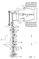
- the mowing device 1 illustrated in Fig. 1 is attached, by means of frame 5, to the three-point suspension 4 of a tractor 2 which can move in a forward direction A.
- a power take-off 3 is connected to the mowing device for driving the former.
- the frame 5 has a transversely projecting mowing beam 6, which accommodates a drive mechanism (not shown) which is coupled to the power take-off 3.
- the mowing beam furthermore has a series of cutting disc assemblies 7, the disc assemblies 7a of which rotate in the one direction B and the disc assemblies 7b rotate in the opposite direction C.
- the cutting disc assemblies have two blades 8 situated at opposite positions.
- Each blade 8 is provided with a cutting edge 9, which is directed in the direction of rotation C.
- each blade 8 is attached to a dedicated blade holder 11 a, 11 b, each of which is bent and panel-shaped (with the concave side on top) and, viewed in top view, have gaps 30 between them.
- the blade holders 11a,b have a leading edge region 13, which is formed in order to pass plants mowed by the preceding blade upwards, and a trailing edge region 14.
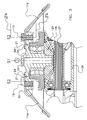
- the blade holders 11a,b are rotatably attached to a flange 21 of a hub 20 by means of bolts 15, illustrated in more detail in Fig.
- the blades 8 themselves are attached to the dedicated blade holder 11 a, 11 b so as to be rotatable about rotation axis S3 of the pivot pin 10, with the pivot angle being limited by a stop at the bottom side of the respective blade holder, if desired.
- the rotation axes S1 and S3 are vertical and parallel to one another.
- the blade holders 11a,b are furthermore fixed to the flange 21 by means of breaking pins 16, as a result of which, during normal operation, without impact, they are held against rotation about rotation axis S2. However, following breaking of the breaking pin 16, they are potentially rotatable about said axis.
- the hub 20 is attached to a gearwheel 25 which is driven by a drive shaft 27 via a right-angled transmission with gearwheel 26.
- the drive shaft 27 is indirectly driven by the power take-off 3 and extends in the longitudinal direction of the mowing beam 6 through housing 28 and drives several cutting disc assemblies which are arranged next to one another.
- the central rotation axis S1 of the cutting disc assembly 7 is indicated.
- the outer path X1 of the ends of the blades 8, having a radius R1 is indicated and the outer path Y1 of the edge of the blade holders 11a,b is, having a radius R3, indicated.
- the blade holder By drawing a radial T running through hinge 15, the blade holder can be seen divided into a first portion I and a second portion II, which also carries the blade 8.
- the first portion I has a mass which is greater than that of the second portion II.
- a blade 8 hits a hard foreign object, such as a stone, the blade can turn inwards about rotation axis S3. If the impact force experienced exceeds a specific value, the respective blade holder 11a, 11b can exert a force on the connection with the hub 20, as a result of which the breaking force of the breaking pin 16 is exceeded. This may also occur when the blade holder 11a, 11b itself hits the foreign object. In this case, it should be considered, that the speed in the direction A may be 15 km/h and the rotary speed of the cutting disc assembly 7 may be 3000/min. As a result of the breaking of the breaking pin 16, the respective blade holder remains connected to the hub 20 only at the location of bolt 15.
- portion I As a result of the larger mass of portion I, the latter will bend outwards and the second portion II will bend inwards about the hinge 15 and rotation axis S2.
- the outer path X2 of the respective blade end will now take up a smaller radius R2.
- the outer path Y2 of the edge of the blade holders 11a,b will also take up a smaller radius R4. The same will happen if the other blade and/or the other blade holder also hits the same hard object.
- the two blade ends and blade holders remain in the retracted position, in which they are outside the path of the blade ends and blade holders of the adjacent cutting disc assemblies.
- a stop 24 may be provided on the hub or the other blade holder by means of which the blade holder is held in the position from Fig. 3 .
- a clamping means may be provided on the hub 20 or on the other blade holder 11 b; 11 a, by means of which the inward rotation of the blade holder 11 a; 11 b is limited.
- breaking pins 16 into a single shearing connection which is active directly between both blade holders 11a,b, for example in the form of a pull strip (not shown).
- the blade holders may overlap at the location of a single breaking pin which extends through both blade holders and the rest of the rotor, such as hub 20.
- the rotation axis S2 may be allowed to be at an angle, by designing the hole in the flange 21 for the bolt 15 accordingly ( Fig. 4A ).
- the angle ⁇ of the ascending surfaces 29 and of rotation axis S2 may be in the order of magnitude of 10-20 degrees, so that the vertical displacement can take place quickly.
- the direction of the inclination can be related to the cutting edge of the blade 8, in particular the end thereof, so that this moves directly upwards after the breaking pin 16 has broken. In Fig.
- the line v has been rendered as a spot, which line, on the one hand, contains the intersection of a vertical and the rotation axis S2 and contains, on the other hand, the end of the cutting edge of the blade 8 (see also Fig. 4 ).
- the rotation axis will be situated in the upward direction on the trailing side (based on the direction of rotation D after impact) of the vertical.
- the rotation axis S2 is in this case inclined at an angle ⁇ of, for example, the abovementioned 10-20 degrees.
Landscapes
- Life Sciences & Earth Sciences (AREA)
- Environmental Sciences (AREA)
- Harvester Elements (AREA)
Priority Applications (6)
| Application Number | Priority Date | Filing Date | Title |
|---|---|---|---|
| EP12165759.7A EP2520149B1 (de) | 2008-02-18 | 2009-02-11 | Mähvorrichtung |
| PL12165761T PL2520150T3 (pl) | 2008-02-18 | 2009-02-11 | Urządzenie do koszenia |
| PL12165759T PL2520149T3 (pl) | 2008-02-18 | 2009-02-11 | Urządzenie do koszenia |
| DK12165759.7T DK2520149T3 (da) | 2008-02-18 | 2009-02-11 | Slåindretning |
| EP12165761.3A EP2520150B1 (de) | 2008-02-18 | 2009-02-11 | Mähvorrichtung |
| DK12165761.3T DK2520150T3 (da) | 2008-02-18 | 2009-02-11 | Slåindretning |
Applications Claiming Priority (1)
| Application Number | Priority Date | Filing Date | Title |
|---|---|---|---|
| NL1035035A NL1035035C2 (nl) | 2008-02-18 | 2008-02-18 | Maai-inrichting. |
Related Child Applications (2)
| Application Number | Title | Priority Date | Filing Date |
|---|---|---|---|
| EP12165759.7A Division-Into EP2520149B1 (de) | 2008-02-18 | 2009-02-11 | Mähvorrichtung |
| EP12165761.3A Division-Into EP2520150B1 (de) | 2008-02-18 | 2009-02-11 | Mähvorrichtung |
Publications (3)
| Publication Number | Publication Date |
|---|---|
| EP2090150A2 true EP2090150A2 (de) | 2009-08-19 |
| EP2090150A3 EP2090150A3 (de) | 2009-11-18 |
| EP2090150B1 EP2090150B1 (de) | 2018-08-29 |
Family
ID=39760838
Family Applications (3)
| Application Number | Title | Priority Date | Filing Date |
|---|---|---|---|
| EP12165759.7A Not-in-force EP2520149B1 (de) | 2008-02-18 | 2009-02-11 | Mähvorrichtung |
| EP09075069.6A Not-in-force EP2090150B1 (de) | 2008-02-18 | 2009-02-11 | Mähvorrichtung |
| EP12165761.3A Not-in-force EP2520150B1 (de) | 2008-02-18 | 2009-02-11 | Mähvorrichtung |
Family Applications Before (1)
| Application Number | Title | Priority Date | Filing Date |
|---|---|---|---|
| EP12165759.7A Not-in-force EP2520149B1 (de) | 2008-02-18 | 2009-02-11 | Mähvorrichtung |
Family Applications After (1)
| Application Number | Title | Priority Date | Filing Date |
|---|---|---|---|
| EP12165761.3A Not-in-force EP2520150B1 (de) | 2008-02-18 | 2009-02-11 | Mähvorrichtung |
Country Status (5)
| Country | Link |
|---|---|
| US (3) | US8205423B2 (de) |
| EP (3) | EP2520149B1 (de) |
| DK (2) | DK2520149T3 (de) |
| NL (1) | NL1035035C2 (de) |
| PL (2) | PL2520150T3 (de) |
Cited By (1)
| Publication number | Priority date | Publication date | Assignee | Title |
|---|---|---|---|---|
| ITMI20101660A1 (it) * | 2010-09-13 | 2012-03-14 | Feraboli S P A | Gruppo falciante a dischi, particolarmente per macchine agricole del tipo falciatrici, falciacondizionatrici o simili, ad elevata sicurezza di impiego. |
Families Citing this family (9)
| Publication number | Priority date | Publication date | Assignee | Title |
|---|---|---|---|---|
| NL1035035C2 (nl) * | 2008-02-18 | 2009-08-19 | Lely Patent Nv | Maai-inrichting. |
| US8695316B2 (en) * | 2011-02-21 | 2014-04-15 | Agco Corporation | Fixed rotary knife with multiple cutting surfaces |
| EP2760270B1 (de) | 2011-09-29 | 2016-11-16 | Husqvarna AB | Schnellwechsel-schaufelsystem |
| US10188031B2 (en) * | 2016-01-27 | 2019-01-29 | Great Plains Manufacturing, Inc. | Cutter blade and assembly for a rotary cutter |
| US11470773B2 (en) | 2017-08-02 | 2022-10-18 | Briggs & Stratton, Llc | Stand-on mower with an oscillating front axle |
| US10820499B2 (en) * | 2018-06-08 | 2020-11-03 | Cnh Industrial America Llc | Hybrid disc cutting system having a knife mount for an agricultural vehicle |
| DE102020119368B4 (de) * | 2020-07-22 | 2024-10-24 | Maschinenfabrik Bernard Krone GmbH & Co. KG | Schneidvorrichtung |
| PL245898B1 (pl) * | 2021-03-17 | 2024-10-28 | Osrodek Techniki Lesnej | Urządzenie do wykaszania, zwłaszcza obszarów leśnych |
| US12376519B2 (en) | 2022-06-14 | 2025-08-05 | Deere & Company | Quick change blade for a rotating blade assembly of a mower implement |
Citations (2)
| Publication number | Priority date | Publication date | Assignee | Title |
|---|---|---|---|---|
| US3397525A (en) | 1965-07-01 | 1968-08-20 | Int Harvester Co | Breakaway knife holder |
| WO2006135952A1 (en) | 2005-04-29 | 2006-12-28 | Raymond Eric Abernethy | A cutting blade assembly for a mower |
Family Cites Families (60)
| Publication number | Priority date | Publication date | Assignee | Title |
|---|---|---|---|---|
| US1220353A (en) * | 1916-02-21 | 1917-03-27 | Lindbladh Corp | Delivery device. |
| US2547540A (en) * | 1946-03-14 | 1951-04-03 | Wiley T Roberts | Power mower |
| US2634571A (en) * | 1951-05-07 | 1953-04-14 | Forby W Lawrence | Rotary hinged disk type mower |
| US2856747A (en) * | 1955-09-30 | 1958-10-21 | Ernest W Kolls | Cutting blade for rotary type mowing machines |
| US2963844A (en) * | 1959-04-20 | 1960-12-13 | John F Engler | Mower blade |
| US3184907A (en) * | 1964-03-16 | 1965-05-25 | Werner B Harloff | Power mower |
| US3320732A (en) * | 1965-02-17 | 1967-05-23 | Ralph D Kirk | Cutting blade assembly for rotary lawn mowers and the like |
| US3507104A (en) * | 1967-05-25 | 1970-04-21 | Sperry Rand Corp | Knife mounting |
| US3500622A (en) * | 1967-08-17 | 1970-03-17 | Marvin Bowen | Mower cutting blade |
| GB1220353A (en) * | 1967-10-27 | 1971-01-27 | Bamlett Ltd A C | Improvements in or relating to flail mowers and flail shaft arrangements therefor |
| DE6811860U (de) * | 1968-12-18 | 1969-05-14 | Welger Geb | Messerbefestigung an scheiben- oder trommelmaehwerken |
| GB1321595A (en) * | 1969-07-16 | 1973-06-27 | Kidd A W | Machines for cutting crops |
| US3621642A (en) * | 1970-10-09 | 1971-11-23 | Harry A Leake Jr | Rotary cutter head assembly for lawn mowers |
| US3715874A (en) * | 1971-10-01 | 1973-02-13 | C Goserud | Lawn mower cutters |
| US3690051A (en) * | 1971-12-28 | 1972-09-12 | Black & Decker Mfg Co | Safety lawnmower blade |
| DE2316308A1 (de) * | 1973-03-31 | 1974-10-17 | Mang Albert | Maehmaschine, insbesondere rasen-maehmaschine |
| CA1005648A (en) * | 1974-05-10 | 1977-02-22 | International Harvester Company | Cutter blade mounting for a rotary mower |
| US3918241A (en) * | 1974-10-16 | 1975-11-11 | Herbert C Stillions | Cutting unit for rotary lawn mowers |
| US4058959A (en) * | 1975-10-06 | 1977-11-22 | Moss Robert J | Grass cutting blades |
| NL7513925A (nl) * | 1975-11-28 | 1977-06-01 | Multinorm Bv | Maaiinrichting. |
| US4062171A (en) * | 1976-08-30 | 1977-12-13 | Massey-Ferguson Inc. | Cutter blade assembly |
| US4114354A (en) * | 1976-11-05 | 1978-09-19 | Outboard Marine Corporation | Lawn mower blade mounting |
| US4345420A (en) * | 1977-09-12 | 1982-08-24 | Multinorm, B.V. | Mowing implement |
| US4158944A (en) * | 1977-09-20 | 1979-06-26 | Hall & Myers | Rotary blade coupling for lawn mower |
| US4258536A (en) * | 1979-02-07 | 1981-03-31 | Outboard Marine Corporation | Power rotary cutting blade with retractable cutting knives |
| DE2920244C2 (de) * | 1979-05-18 | 1986-10-23 | Klöckner-Humboldt-Deutz AG Zweigniederlassung Fahr, 7702 Gottmadingen | Kreiselmäher |
| NL8101567A (nl) * | 1981-03-30 | 1981-08-03 | Multinorm Bv | Maaiinrichting. |
| NL8103411A (nl) * | 1981-07-17 | 1983-02-16 | Multinorm Bv | Maaier. |
| NL8104178A (nl) * | 1981-09-10 | 1983-04-05 | Lely Nv C Van Der | Flexibele maaikap. |
| NL8105634A (nl) * | 1981-12-15 | 1983-07-01 | Zweegers P | Inrichting voor het maaien van gewas. |
| NL8400028A (nl) * | 1984-01-04 | 1985-08-01 | Lely Nv C Van Der | Maaimachine. |
| US4651510A (en) * | 1985-04-08 | 1987-03-24 | Malutich William J | Blade for rotary lawn mower |
| US4804047A (en) * | 1985-11-20 | 1989-02-14 | Kobashi Kogyo Co., Ltd. | Rotary mower and tilling device |
| FR2638056B1 (fr) * | 1988-10-26 | 1991-06-07 | Kuhn Sa | Faucheuse avec montage perfectionne des organes de coupe |
| DK162802C (da) * | 1989-04-20 | 1992-05-04 | Spragelse Maskinfabrik As | Rotorklipper |
| US5271212A (en) * | 1992-12-23 | 1993-12-21 | Anderson Ray S | Lawnmower blade with yieldable opposite outer cutting sections |
| US5581985A (en) * | 1995-06-15 | 1996-12-10 | Secosky; Paul M. | Safety clutches for self power operated lawn mowers |
| CA2178535C (en) * | 1995-08-30 | 1999-08-31 | Deere & Company | Shredding attachment for rotary cutter |
| US5649413A (en) * | 1995-11-14 | 1997-07-22 | Oostendorp; William E. | Grass trimming and lawn edging device |
| US5715662A (en) * | 1995-11-17 | 1998-02-10 | Deere & Company | Drive shear device for rotary cutter unit |
| US5791131A (en) * | 1996-04-22 | 1998-08-11 | Snapper, Inc. | Convertible mower blade |
| AUPO739097A0 (en) * | 1997-06-16 | 1997-07-10 | Thorne, Peter | Improved brush cutting tool |
| DE19748475C2 (de) * | 1997-11-03 | 1999-08-19 | Horst Staiger & Soehne Gmbh | Mähwerk für Rasenmäher |
| WO1999041966A1 (en) * | 1998-02-20 | 1999-08-26 | The Black & Decker Corporation | Combination string and blade trimmer with auxiliary blower function |
| FR2776953B1 (fr) * | 1998-04-07 | 2001-10-12 | Edouard Boisson | Organe de coupe semi-rigide a rendement ameliore |
| US20020095921A1 (en) * | 2001-01-25 | 2002-07-25 | The Master's Dredging Company, Inc. | Airboat with aquatic vegetation shredding assembly |
| US6604347B2 (en) * | 2001-04-27 | 2003-08-12 | New Holland North America, Inc. | Energy absorber for hubs of agricultural disc drive |
| US6502377B2 (en) * | 2001-04-27 | 2003-01-07 | New Holland North America, Inc. | Brake for a disc cutterbar |
| US6487835B2 (en) * | 2001-04-27 | 2002-12-03 | New Holland North America, Inc. | Overload protection for a disc cutterbar |
| US6688193B2 (en) * | 2002-01-24 | 2004-02-10 | Deere & Company | Rotary blade cutterbar including plastic idler gear support hub with metal insert |
| US6675563B1 (en) * | 2002-08-19 | 2004-01-13 | New Holland North America, Inc | Disc cutterbar shear protection |
| US6834486B2 (en) * | 2003-03-12 | 2004-12-28 | Vermeer Manufacturing Company | Pivotal knife mounting arrangement |
| US7490459B2 (en) * | 2003-03-12 | 2009-02-17 | Vermeer Manufacturing Company | Mowing device, a knife adapter for such a mowing device and a retainer for such a mowing device |
| US20050193706A1 (en) * | 2003-03-12 | 2005-09-08 | Kent Thompson | Mowing device, a knife adapter for such a mowing device and a retainer for such a mowing device |
| US6829878B1 (en) * | 2004-03-29 | 2004-12-14 | Cnh America Llc | Quick change disc knife mounting mechanism |
| US20060021316A1 (en) * | 2004-07-28 | 2006-02-02 | Harkcom Melanie W | Disc cutterbar shear device |
| US7506494B2 (en) * | 2005-01-18 | 2009-03-24 | Commercial Turf Products, Ltd. | Pivot-blade cutting and retaining means for rotary mowers |
| US7543432B1 (en) * | 2008-01-29 | 2009-06-09 | Honda Motor Co., Ltd. | Retractable blade cutting apparatuses and methods for mowing machines |
| NL1035035C2 (nl) * | 2008-02-18 | 2009-08-19 | Lely Patent Nv | Maai-inrichting. |
| WO2010151871A2 (en) * | 2009-06-26 | 2010-12-29 | Leonardi Manufacturing Co. Inc. | Electrically-powered combination lawn mower, trimmer and edger |
-
2008
- 2008-02-18 NL NL1035035A patent/NL1035035C2/nl not_active IP Right Cessation
-
2009
- 2009-02-11 EP EP12165759.7A patent/EP2520149B1/de not_active Not-in-force
- 2009-02-11 EP EP09075069.6A patent/EP2090150B1/de not_active Not-in-force
- 2009-02-11 DK DK12165759.7T patent/DK2520149T3/da active
- 2009-02-11 DK DK12165761.3T patent/DK2520150T3/da active
- 2009-02-11 EP EP12165761.3A patent/EP2520150B1/de not_active Not-in-force
- 2009-02-11 PL PL12165761T patent/PL2520150T3/pl unknown
- 2009-02-11 PL PL12165759T patent/PL2520149T3/pl unknown
- 2009-02-13 US US12/370,658 patent/US8205423B2/en not_active Expired - Fee Related
-
2012
- 2012-05-25 US US13/480,537 patent/US8707665B2/en active Active
-
2014
- 2014-03-05 US US14/197,237 patent/US20140182258A1/en not_active Abandoned
Patent Citations (2)
| Publication number | Priority date | Publication date | Assignee | Title |
|---|---|---|---|---|
| US3397525A (en) | 1965-07-01 | 1968-08-20 | Int Harvester Co | Breakaway knife holder |
| WO2006135952A1 (en) | 2005-04-29 | 2006-12-28 | Raymond Eric Abernethy | A cutting blade assembly for a mower |
Cited By (2)
| Publication number | Priority date | Publication date | Assignee | Title |
|---|---|---|---|---|
| ITMI20101660A1 (it) * | 2010-09-13 | 2012-03-14 | Feraboli S P A | Gruppo falciante a dischi, particolarmente per macchine agricole del tipo falciatrici, falciacondizionatrici o simili, ad elevata sicurezza di impiego. |
| WO2012034872A1 (en) * | 2010-09-13 | 2012-03-22 | Feraboli S.P.A. | Disc cutter assembly, particularly for farming machines such as mowers, mower conditioners or the like, with high safety of operation |
Also Published As
| Publication number | Publication date |
|---|---|
| DK2520149T3 (da) | 2014-02-03 |
| US20090205305A1 (en) | 2009-08-20 |
| US8205423B2 (en) | 2012-06-26 |
| US20140182258A1 (en) | 2014-07-03 |
| NL1035035C2 (nl) | 2009-08-19 |
| US20120240545A1 (en) | 2012-09-27 |
| PL2520150T3 (pl) | 2014-05-30 |
| EP2090150A3 (de) | 2009-11-18 |
| PL2520149T3 (pl) | 2014-05-30 |
| EP2520150A1 (de) | 2012-11-07 |
| DK2520150T3 (da) | 2014-02-10 |
| EP2520149A1 (de) | 2012-11-07 |
| EP2520150B1 (de) | 2013-12-25 |
| EP2090150B1 (de) | 2018-08-29 |
| US8707665B2 (en) | 2014-04-29 |
| EP2520149B1 (de) | 2013-12-04 |
Similar Documents
| Publication | Publication Date | Title |
|---|---|---|
| US8707665B2 (en) | Cutting disc assembly for a mowing device | |
| US5784866A (en) | Disc cutterbar for agricultural implements | |
| US5809757A (en) | Protective structure for a modular disc cutterbar | |
| US8585367B2 (en) | Wind turbine, a method for servicing a main bearing unit of a wind turbine and use thereof | |
| US4757211A (en) | Machine for generating electricity | |
| DK167513B1 (da) | Mejemaskine | |
| US3905182A (en) | Rotary mower | |
| US6484811B1 (en) | Mulching unit for use in mulching apparatus | |
| JP2009106257A (ja) | 草刈機用刃物盤 | |
| EP3011820A1 (de) | Kopf für einen kantentrimmer | |
| US20100043378A1 (en) | cutting blade assembly for a mower | |
| US20190001336A1 (en) | Centrifugal Pulverizing Mill | |
| US3540198A (en) | Swing knife assembly for a rotary mower | |
| US5715663A (en) | Crop mover for rotary disc cutter | |
| CN111432627B (zh) | 用于收割机械的辊和辊组、收割机械以及割台 | |
| US20110011049A1 (en) | Mowing device | |
| CN109667707B (zh) | 风力发电装置 | |
| CA2531189A1 (en) | Blade for a crop harvesting header with rotary disks | |
| US20060213170A1 (en) | Blade for a crop harvesting header with rotary disks | |
| US9234549B2 (en) | Torsional coupling for a mobile attachment device | |
| FI131707B1 (sv) | Drivenhet för tallriksslåttermaskin | |
| JP6773479B2 (ja) | 草刈機 | |
| JP4444063B2 (ja) | マルチングモア | |
| CN105052432A (zh) | 切草器 | |
| KR200367628Y1 (ko) | 예초기용 예초날 |
Legal Events
| Date | Code | Title | Description |
|---|---|---|---|
| PUAI | Public reference made under article 153(3) epc to a published international application that has entered the european phase |
Free format text: ORIGINAL CODE: 0009012 |
|
| AK | Designated contracting states |
Kind code of ref document: A2 Designated state(s): AT BE BG CH CY CZ DE DK EE ES FI FR GB GR HR HU IE IS IT LI LT LU LV MC MK MT NL NO PL PT RO SE SI SK TR |
|
| AX | Request for extension of the european patent |
Extension state: AL BA RS |
|
| PUAL | Search report despatched |
Free format text: ORIGINAL CODE: 0009013 |
|
| AK | Designated contracting states |
Kind code of ref document: A3 Designated state(s): AT BE BG CH CY CZ DE DK EE ES FI FR GB GR HR HU IE IS IT LI LT LU LV MC MK MT NL NO PL PT RO SE SI SK TR |
|
| AX | Request for extension of the european patent |
Extension state: AL BA RS |
|
| 17P | Request for examination filed |
Effective date: 20100325 |
|
| 17Q | First examination report despatched |
Effective date: 20100503 |
|
| AKX | Designation fees paid |
Designated state(s): AT BE BG CH CY CZ DE DK EE ES FI FR GB GR HR HU IE IS IT LI LT LU LV MC MK MT NL NO PL PT RO SE SI SK TR |
|
| RAP1 | Party data changed (applicant data changed or rights of an application transferred) |
Owner name: LELY PATENT N.V. |
|
| GRAP | Despatch of communication of intention to grant a patent |
Free format text: ORIGINAL CODE: EPIDOSNIGR1 |
|
| STAA | Information on the status of an ep patent application or granted ep patent |
Free format text: STATUS: GRANT OF PATENT IS INTENDED |
|
| INTG | Intention to grant announced |
Effective date: 20180424 |
|
| GRAS | Grant fee paid |
Free format text: ORIGINAL CODE: EPIDOSNIGR3 |
|
| GRAA | (expected) grant |
Free format text: ORIGINAL CODE: 0009210 |
|
| STAA | Information on the status of an ep patent application or granted ep patent |
Free format text: STATUS: THE PATENT HAS BEEN GRANTED |
|
| AK | Designated contracting states |
Kind code of ref document: B1 Designated state(s): AT BE BG CH CY CZ DE DK EE ES FI FR GB GR HR HU IE IS IT LI LT LU LV MC MK MT NL NO PL PT RO SE SI SK TR |
|
| REG | Reference to a national code |
Ref country code: GB Ref legal event code: FG4D |
|
| REG | Reference to a national code |
Ref country code: CH Ref legal event code: EP |
|
| REG | Reference to a national code |
Ref country code: AT Ref legal event code: REF Ref document number: 1034053 Country of ref document: AT Kind code of ref document: T Effective date: 20180915 |
|
| REG | Reference to a national code |
Ref country code: IE Ref legal event code: FG4D |
|
| REG | Reference to a national code |
Ref country code: DE Ref legal event code: R096 Ref document number: 602009054118 Country of ref document: DE |
|
| REG | Reference to a national code |
Ref country code: NL Ref legal event code: MP Effective date: 20180829 |
|
| REG | Reference to a national code |
Ref country code: LT Ref legal event code: MG4D |
|
| PG25 | Lapsed in a contracting state [announced via postgrant information from national office to epo] |
Ref country code: FI Free format text: LAPSE BECAUSE OF FAILURE TO SUBMIT A TRANSLATION OF THE DESCRIPTION OR TO PAY THE FEE WITHIN THE PRESCRIBED TIME-LIMIT Effective date: 20180829 Ref country code: NO Free format text: LAPSE BECAUSE OF FAILURE TO SUBMIT A TRANSLATION OF THE DESCRIPTION OR TO PAY THE FEE WITHIN THE PRESCRIBED TIME-LIMIT Effective date: 20181129 Ref country code: IS Free format text: LAPSE BECAUSE OF FAILURE TO SUBMIT A TRANSLATION OF THE DESCRIPTION OR TO PAY THE FEE WITHIN THE PRESCRIBED TIME-LIMIT Effective date: 20181229 Ref country code: LT Free format text: LAPSE BECAUSE OF FAILURE TO SUBMIT A TRANSLATION OF THE DESCRIPTION OR TO PAY THE FEE WITHIN THE PRESCRIBED TIME-LIMIT Effective date: 20180829 Ref country code: SE Free format text: LAPSE BECAUSE OF FAILURE TO SUBMIT A TRANSLATION OF THE DESCRIPTION OR TO PAY THE FEE WITHIN THE PRESCRIBED TIME-LIMIT Effective date: 20180829 Ref country code: BG Free format text: LAPSE BECAUSE OF FAILURE TO SUBMIT A TRANSLATION OF THE DESCRIPTION OR TO PAY THE FEE WITHIN THE PRESCRIBED TIME-LIMIT Effective date: 20181129 Ref country code: NL Free format text: LAPSE BECAUSE OF FAILURE TO SUBMIT A TRANSLATION OF THE DESCRIPTION OR TO PAY THE FEE WITHIN THE PRESCRIBED TIME-LIMIT Effective date: 20180829 Ref country code: GR Free format text: LAPSE BECAUSE OF FAILURE TO SUBMIT A TRANSLATION OF THE DESCRIPTION OR TO PAY THE FEE WITHIN THE PRESCRIBED TIME-LIMIT Effective date: 20181130 |
|
| REG | Reference to a national code |
Ref country code: AT Ref legal event code: MK05 Ref document number: 1034053 Country of ref document: AT Kind code of ref document: T Effective date: 20180829 |
|
| PG25 | Lapsed in a contracting state [announced via postgrant information from national office to epo] |
Ref country code: LV Free format text: LAPSE BECAUSE OF FAILURE TO SUBMIT A TRANSLATION OF THE DESCRIPTION OR TO PAY THE FEE WITHIN THE PRESCRIBED TIME-LIMIT Effective date: 20180829 Ref country code: HR Free format text: LAPSE BECAUSE OF FAILURE TO SUBMIT A TRANSLATION OF THE DESCRIPTION OR TO PAY THE FEE WITHIN THE PRESCRIBED TIME-LIMIT Effective date: 20180829 Ref country code: ES Free format text: LAPSE BECAUSE OF FAILURE TO SUBMIT A TRANSLATION OF THE DESCRIPTION OR TO PAY THE FEE WITHIN THE PRESCRIBED TIME-LIMIT Effective date: 20180829 |
|
| PG25 | Lapsed in a contracting state [announced via postgrant information from national office to epo] |
Ref country code: PL Free format text: LAPSE BECAUSE OF FAILURE TO SUBMIT A TRANSLATION OF THE DESCRIPTION OR TO PAY THE FEE WITHIN THE PRESCRIBED TIME-LIMIT Effective date: 20180829 Ref country code: RO Free format text: LAPSE BECAUSE OF FAILURE TO SUBMIT A TRANSLATION OF THE DESCRIPTION OR TO PAY THE FEE WITHIN THE PRESCRIBED TIME-LIMIT Effective date: 20180829 Ref country code: IT Free format text: LAPSE BECAUSE OF FAILURE TO SUBMIT A TRANSLATION OF THE DESCRIPTION OR TO PAY THE FEE WITHIN THE PRESCRIBED TIME-LIMIT Effective date: 20180829 Ref country code: CZ Free format text: LAPSE BECAUSE OF FAILURE TO SUBMIT A TRANSLATION OF THE DESCRIPTION OR TO PAY THE FEE WITHIN THE PRESCRIBED TIME-LIMIT Effective date: 20180829 Ref country code: EE Free format text: LAPSE BECAUSE OF FAILURE TO SUBMIT A TRANSLATION OF THE DESCRIPTION OR TO PAY THE FEE WITHIN THE PRESCRIBED TIME-LIMIT Effective date: 20180829 Ref country code: AT Free format text: LAPSE BECAUSE OF FAILURE TO SUBMIT A TRANSLATION OF THE DESCRIPTION OR TO PAY THE FEE WITHIN THE PRESCRIBED TIME-LIMIT Effective date: 20180829 |
|
| PG25 | Lapsed in a contracting state [announced via postgrant information from national office to epo] |
Ref country code: DK Free format text: LAPSE BECAUSE OF FAILURE TO SUBMIT A TRANSLATION OF THE DESCRIPTION OR TO PAY THE FEE WITHIN THE PRESCRIBED TIME-LIMIT Effective date: 20180829 Ref country code: SK Free format text: LAPSE BECAUSE OF FAILURE TO SUBMIT A TRANSLATION OF THE DESCRIPTION OR TO PAY THE FEE WITHIN THE PRESCRIBED TIME-LIMIT Effective date: 20180829 |
|
| REG | Reference to a national code |
Ref country code: DE Ref legal event code: R097 Ref document number: 602009054118 Country of ref document: DE |
|
| PLBE | No opposition filed within time limit |
Free format text: ORIGINAL CODE: 0009261 |
|
| STAA | Information on the status of an ep patent application or granted ep patent |
Free format text: STATUS: NO OPPOSITION FILED WITHIN TIME LIMIT |
|
| 26N | No opposition filed |
Effective date: 20190531 |
|
| PG25 | Lapsed in a contracting state [announced via postgrant information from national office to epo] |
Ref country code: SI Free format text: LAPSE BECAUSE OF FAILURE TO SUBMIT A TRANSLATION OF THE DESCRIPTION OR TO PAY THE FEE WITHIN THE PRESCRIBED TIME-LIMIT Effective date: 20180829 |
|
| REG | Reference to a national code |
Ref country code: CH Ref legal event code: PL |
|
| GBPC | Gb: european patent ceased through non-payment of renewal fee |
Effective date: 20190211 |
|
| PG25 | Lapsed in a contracting state [announced via postgrant information from national office to epo] |
Ref country code: LU Free format text: LAPSE BECAUSE OF NON-PAYMENT OF DUE FEES Effective date: 20190211 Ref country code: MC Free format text: LAPSE BECAUSE OF FAILURE TO SUBMIT A TRANSLATION OF THE DESCRIPTION OR TO PAY THE FEE WITHIN THE PRESCRIBED TIME-LIMIT Effective date: 20180829 |
|
| REG | Reference to a national code |
Ref country code: BE Ref legal event code: MM Effective date: 20190228 |
|
| REG | Reference to a national code |
Ref country code: IE Ref legal event code: MM4A |
|
| PG25 | Lapsed in a contracting state [announced via postgrant information from national office to epo] |
Ref country code: CH Free format text: LAPSE BECAUSE OF NON-PAYMENT OF DUE FEES Effective date: 20190228 Ref country code: LI Free format text: LAPSE BECAUSE OF NON-PAYMENT OF DUE FEES Effective date: 20190228 |
|
| PG25 | Lapsed in a contracting state [announced via postgrant information from national office to epo] |
Ref country code: IE Free format text: LAPSE BECAUSE OF NON-PAYMENT OF DUE FEES Effective date: 20190211 Ref country code: GB Free format text: LAPSE BECAUSE OF NON-PAYMENT OF DUE FEES Effective date: 20190211 |
|
| PG25 | Lapsed in a contracting state [announced via postgrant information from national office to epo] |
Ref country code: BE Free format text: LAPSE BECAUSE OF NON-PAYMENT OF DUE FEES Effective date: 20190228 |
|
| PG25 | Lapsed in a contracting state [announced via postgrant information from national office to epo] |
Ref country code: TR Free format text: LAPSE BECAUSE OF FAILURE TO SUBMIT A TRANSLATION OF THE DESCRIPTION OR TO PAY THE FEE WITHIN THE PRESCRIBED TIME-LIMIT Effective date: 20180829 |
|
| PG25 | Lapsed in a contracting state [announced via postgrant information from national office to epo] |
Ref country code: MT Free format text: LAPSE BECAUSE OF NON-PAYMENT OF DUE FEES Effective date: 20190211 Ref country code: PT Free format text: LAPSE BECAUSE OF FAILURE TO SUBMIT A TRANSLATION OF THE DESCRIPTION OR TO PAY THE FEE WITHIN THE PRESCRIBED TIME-LIMIT Effective date: 20181229 |
|
| PG25 | Lapsed in a contracting state [announced via postgrant information from national office to epo] |
Ref country code: CY Free format text: LAPSE BECAUSE OF FAILURE TO SUBMIT A TRANSLATION OF THE DESCRIPTION OR TO PAY THE FEE WITHIN THE PRESCRIBED TIME-LIMIT Effective date: 20180829 |
|
| PG25 | Lapsed in a contracting state [announced via postgrant information from national office to epo] |
Ref country code: HU Free format text: LAPSE BECAUSE OF FAILURE TO SUBMIT A TRANSLATION OF THE DESCRIPTION OR TO PAY THE FEE WITHIN THE PRESCRIBED TIME-LIMIT; INVALID AB INITIO Effective date: 20090211 |
|
| PGFP | Annual fee paid to national office [announced via postgrant information from national office to epo] |
Ref country code: DE Payment date: 20220217 Year of fee payment: 14 |
|
| PGFP | Annual fee paid to national office [announced via postgrant information from national office to epo] |
Ref country code: FR Payment date: 20220217 Year of fee payment: 14 |
|
| PG25 | Lapsed in a contracting state [announced via postgrant information from national office to epo] |
Ref country code: MK Free format text: LAPSE BECAUSE OF FAILURE TO SUBMIT A TRANSLATION OF THE DESCRIPTION OR TO PAY THE FEE WITHIN THE PRESCRIBED TIME-LIMIT Effective date: 20180829 |
|
| REG | Reference to a national code |
Ref country code: DE Ref legal event code: R119 Ref document number: 602009054118 Country of ref document: DE |
|
| PG25 | Lapsed in a contracting state [announced via postgrant information from national office to epo] |
Ref country code: FR Free format text: LAPSE BECAUSE OF NON-PAYMENT OF DUE FEES Effective date: 20230228 Ref country code: DE Free format text: LAPSE BECAUSE OF NON-PAYMENT OF DUE FEES Effective date: 20230901 |