EP2088079A2 - Dispositif antichute - Google Patents
Dispositif antichute Download PDFInfo
- Publication number
- EP2088079A2 EP2088079A2 EP09152077A EP09152077A EP2088079A2 EP 2088079 A2 EP2088079 A2 EP 2088079A2 EP 09152077 A EP09152077 A EP 09152077A EP 09152077 A EP09152077 A EP 09152077A EP 2088079 A2 EP2088079 A2 EP 2088079A2
- Authority
- EP
- European Patent Office
- Prior art keywords
- rope
- cable
- wing
- damping device
- safety
- Prior art date
- Legal status (The legal status is an assumption and is not a legal conclusion. Google has not performed a legal analysis and makes no representation as to the accuracy of the status listed.)
- Withdrawn
Links
- 238000013016 damping Methods 0.000 claims abstract description 34
- 238000012423 maintenance Methods 0.000 claims description 12
- 238000006073 displacement reaction Methods 0.000 claims description 3
- 239000000835 fiber Substances 0.000 claims description 2
- -1 Polypropylene Polymers 0.000 claims 1
- 239000004743 Polypropylene Substances 0.000 claims 1
- 230000001419 dependent effect Effects 0.000 claims 1
- 239000000463 material Substances 0.000 claims 1
- 229920001155 polypropylene Polymers 0.000 claims 1
- 210000003128 head Anatomy 0.000 description 6
- 238000004140 cleaning Methods 0.000 description 3
- 238000004873 anchoring Methods 0.000 description 2
- 238000004804 winding Methods 0.000 description 2
- 241000120551 Heliconiinae Species 0.000 description 1
- 241000209035 Ilex Species 0.000 description 1
- 238000005299 abrasion Methods 0.000 description 1
- 230000002238 attenuated effect Effects 0.000 description 1
- 230000037396 body weight Effects 0.000 description 1
- 238000011109 contamination Methods 0.000 description 1
- 239000013536 elastomeric material Substances 0.000 description 1
- 230000001771 impaired effect Effects 0.000 description 1
- 230000007246 mechanism Effects 0.000 description 1
- 238000000034 method Methods 0.000 description 1
- 230000001681 protective effect Effects 0.000 description 1
- 230000001960 triggered effect Effects 0.000 description 1
Images

Classifications
-
- A—HUMAN NECESSITIES
- A62—LIFE-SAVING; FIRE-FIGHTING
- A62B—DEVICES, APPARATUS OR METHODS FOR LIFE-SAVING
- A62B35/00—Safety belts or body harnesses; Similar equipment for limiting displacement of the human body, especially in case of sudden changes of motion
- A62B35/04—Safety belts or body harnesses; Similar equipment for limiting displacement of the human body, especially in case of sudden changes of motion incorporating energy absorbing means
-
- B—PERFORMING OPERATIONS; TRANSPORTING
- B64—AIRCRAFT; AVIATION; COSMONAUTICS
- B64F—GROUND OR AIRCRAFT-CARRIER-DECK INSTALLATIONS SPECIALLY ADAPTED FOR USE IN CONNECTION WITH AIRCRAFT; DESIGNING, MANUFACTURING, ASSEMBLING, CLEANING, MAINTAINING OR REPAIRING AIRCRAFT, NOT OTHERWISE PROVIDED FOR; HANDLING, TRANSPORTING, TESTING OR INSPECTING AIRCRAFT COMPONENTS, NOT OTHERWISE PROVIDED FOR
- B64F5/00—Designing, manufacturing, assembling, cleaning, maintaining or repairing aircraft, not otherwise provided for; Handling, transporting, testing or inspecting aircraft components, not otherwise provided for
- B64F5/40—Maintaining or repairing aircraft
Definitions
- the present invention relates to a device for securing persons during maintenance work on aircraft wings, with a tensioned above the wing rope.
- Aircraft wings must be regularly maintained and thoroughly cleaned at relatively short intervals to maintain their aerodynamic properties.
- the wings of passenger aircraft are usually designed so that they have certain zones that may be entered by the maintenance personnel, while other areas should not be entered if possible, so as not to damage the wing or underlying structures.
- the wings of modern passenger jets have in some cases a length of thirty meters and more, the device must be equally functional for securing the people over this entire length.
- the individual Vacuum holding devices not only a correspondingly large area, which is no longer accessible after placing the holding device for the maintenance, but it must also a greater number of corresponding vacuum holding devices along the surface of the support surface are arranged, with a safety rope all vacuum holding devices together and safety lines of each Person in turn secured to the rope and guided.
- both wings in the vicinity of their ends and the hulls of aircraft above the respective wing anchoring at least in the Airbusfamilie. or stop points on which a safety rope could be attached.
- the present invention Compared to this prior art, the present invention, the object of the invention to provide a corresponding device or in such a way that on the one hand much easier and cheaper than the known vacuum holding device, on the other hand, but on no account that of the device claimed aircraft structures are loaded beyond the permissible limits.
- the forces occurring in the rope which may be exercised by a person secured to the rope, which may be an additional personal protective equipment (also referred to as PSA for short), if that person crashes over an edge of the wing, can be limited by the damping device so far that the load limits are not exceeded in the attachment points.
- PSA personal protective equipment
- the PSA in turn comprises i.a. a safety line, which in turn is connected to the rope.
- an additional anchor point is placed approximately in the middle between the attachment points (end points) of the security line, wherein such an anchor point may be a conventional vacuum holding device.
- the damping device is integrated into the cable by selecting a cable with a certain force-elongation behavior, which is selected in such a way that a person falling from a wing (or a falling weight of, for example, 100 kg) Interception causes a force in the rope, the value in the top of z. B. 4 kN does not exceed.
- This process is usually dynamic, that is, in the case of a person's fall, the rope to which the person who crashes is secured by an additional safety line, laterally deflected and there is a force peak when, after a certain fall of the person tensions the safety line, the cable is thereby deflected perpendicular to its clamping direction between the attachment points, thereby increasing the tension in the rope drastically.
- the cable lengthens to such an extent that the above-mentioned force limits are not exceeded.
- This also has the advantage that the force in the jerky exciting safety line to which the secured person hangs, is attenuated.
- the rope elongation per kN is about 1%.
- the value of the elongation should not exceed 4% per kN.
- Preferred values of load elongation are between 0.5 and 2% / kN, in particular between 0.8 and 1.2% / kN
- a cable tensioning device which sets in the rope (possibly variably adjustable) bias.
- the cable tensioning device is designed such that it sets the cable tension to a value between 0.3 and 1 kN, for example to about 0.5 kN. This rope tensioning device ensures that the rope is preloaded at all times and sags slack at any time.
- the latter would mean an additional fall path for a person who falls, before the rope tightens and exerts any force on the damping device, in which case the late-onset damping device additionally releases rope length, so that the distance to the ground remaining for the person may no longer be sufficient would, in order to avoid an impact, especially because of the additional fall distance then even more kinetic energy would be absorbed by the damping device.
- Cable prestressing is also particularly helpful if the cable, due to its force-expansion behavior, comprises an integrated damping device, since the initial elongation of a stretchable cable is often disproportionately large (eg over 4% per kN) and this additional elongation by the pretensioning device is eliminated.
- damping device and the cable tensioning device in a single device, that is, cable tensioning device and damping device are identical to each other or combined as a unit.
- an additional vacuum anchor may be provided approximately in the middle region between the An providingdyaken the tensioned rope, which the tensioned rope against ensures excessive lateral deflections. Otherwise there is a risk with very long cable lengths that, despite a considerable lateral deflection approximately in the middle of the rope, the occurring tension in the rope is not so great that would trigger the damping device or the rope elongation at moderate tension too much lateral deflection which would then lead to a correspondingly deeper fall of a falling person, which would either be violated.
- an additional vacuum holding device involves the mentioned disadvantage that it covers a part of the surface to be serviced or cleaned, in contrast to the prior art, it is only a single vacuum holding device, so that the expense of displacing it once is comparatively low and the costs otherwise caused by the vacuum holding devices are then still drastically reduced if, for example, only a single instead of 6 vacuum holding devices is needed and this would also be used only for very large wings,
- a three-quarter inch thread is provided at the attachment points, these attachment points being provided with a matching threaded bolt which has a cable eye into which either a cable loop can be inserted or on which a snap hook can also be inserted one end of the rope is firmly attached, could be hung.
- Such attachment points are, if they are firmly connected to supporting structural elements of the aircraft or the wing, sufficient to absorb the required tensile forces that can occur when using the damping device according to the invention maximum.
- At least one guide sleeve enclosing the cable is provided, this guide sleeve being designed for connecting a safety line to the cable.
- this guide sleeve always remain on arranged the rope and they have z.
- At least two such guide sleeves are provided so that several people can work simultaneously on the wing and are secured to the rope.
- a corresponding vacuum holder or vacuum anchor is provided, for example, in the middle between the two attachment points, at least one guide sleeve should be provided on both sides of the vacuum anchor, preferably at least two guide sleeves should be provided on both sides of the vacuum anchor. This is particularly useful when the guide sleeves and the vacuum anchor are designed so that the guide sleeves can not be moved over the vacuum anchor away or past this.
- the at least one guide sleeve has a safety clamping device which causes jamming of the guide sleeve on the cable even in the case of sudden longitudinal displacements of the guide sleeve along the cable.
- a safety clamping device which causes jamming of the guide sleeve on the cable even in the case of sudden longitudinal displacements of the guide sleeve along the cable.
- Such clamping devices can, for. B. triggered by inertial sensors or lever mechanisms that respond not only to a quick and sudden movement of the guide sleeve, but also to a very small angle between the rope and the safety sleeve attached to the rope over the guide sleeve.
- the area of the shim plates is at least 100 cm 2 and preferably at least 200 cm 2 each.
- the shims can in the plan view circular or circular sector-shaped, but optionally also triangular, square or be formed polygonal in another way. Preferably, they are made in the signal color red or orange, although it may be possible to use different colored shims, if the color of the wing or the hull does not provide sufficient contrast to red or orange shims.
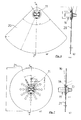
- FIG. 1 in the plan view of the wing of a wide-body aircraft, the wing shape and other details in this case correspond to the wing of the Airbus A 340-300. It can be seen at a distance from the front and rear wing edges of a beginning of the fuselage and reaching almost to the top of the wing field, which is outlined by a dashed line 8, which framed the area that may be entered during maintenance usually while outside of this dashed line lying areas should not be entered if possible.
- a safety rope 2 is fastened between a first attachment point 3 on the fuselage 4 of the aircraft and at a further attachment point 5 in the vicinity of the tip of the support surface 1.
- the tensioning device 7 In the vicinity of the attachment point 3 on the fuselage 4, the tensioning device 7 according to the invention is integrated into the cable 2, while a damping device is effectively realized by the rope 2 showing a specific force-expansion behavior and an expansion between 0.5 and 1.5%. per kN tensile stress having.
- This rope tensioning device can either be a mechanical tensioning device which operates with a spring, an electromechanical tensioning device which has an electromagnetic winding drive or else a hydraulic or pneumatic device which likewise has a corresponding winding drive.
- the tensioning device could in these cases also be used as a damping device, wherein other damping devices and tensioning devices and combinations of different damping and tensioning devices are conceivable, which are known in principle in the prior art and in its detailed embodiment are not the subject of the present invention.
- the cable tensioning device may be adjustable or simply ensures a fixed bias, so that the cable 2 between the two attachment points or An providingdyaken 3, 5 taut.
- the maximum value of this bias should typically be on the order of 0.5 to 2 kN.
- the damping or extensibility of the rope is chosen so that the forces occurring in the event of a fall are below the limits for which the attachment points are designed on the fuselage or on the wing. For many corresponding types of aircraft, values below 6 kN tensile stress are in a safe range below the maximum permissible limits.
- the extensibility of the rope 2 is selected accordingly. If necessary, one can determine the occurring tensile stresses and the required damping properties of the ropes or a separate damping device by simple drop tests with a weight, since these values of the total length of the safety rope, between one of the stop end points and an intervening anchoring freely stretched rope length and the maximum hedged Hang the drop height.
- a 0.5 kN biased safety rope with a load elongation of 1% per kN at a about 30 m long wing and a correspondingly long safety rope with an additional vacuum anchor approximately in the middle between the An anbigdyaken has proven to be a Protect the person against a fall from a height of approximately 3.5 m without exceeding the limit values of the tensile load at the lifting points.
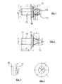
- FIG. 2 shows a side view of a threaded bolt 11 with a threaded portion 15 having a nominal diameter of three quarters of an inch.
- This threaded bolt already has integrated washers 16 and a cable eye 12 at its head end.
- the cable eye 12 is formed by a more or less U-shaped bracket 13 with a nearly rectangular cross section, which is integrally connected to a head plate of the threaded bolt and defines a circular opening with a sufficiently large radius to a safety rope 2, a cable eye or another To be able to pass holding element at the end of the rope.
- the clear diameter of the cable eye is about 12mm.
- FIG. 3 shows the same safety pin 11, however, in a rotated about its axis by 90 ° position, so that in this position the eyelet forming, U-shaped bracket 13 (partially hidden and dashed) is recognizable only as a rectangle from its outside.
- integrated washer 16 and (better recognizable in the drawing of the detail B in FIG. 2 according to FIG. 4 ) A circumferential groove, which serves to receive a large-scale shim.
- FIG. 5 shows a further washer of an elastomeric material whose diameter is approximately equal to that of the integrated washer 16 and whose inner diameter is dimensioned so that it can be moved over the threaded portion 15 away.
- FIG. 6a shows the bolt 11 in a plan view of the head together with an underneath, circular sector-shaped shim 20 which includes a 90 ° sector of a circle with a radius of about 200mm.
- the sectional view again containing the axis of the bolt according to FIG. 6b shows the arrangement of the shim 20 in a circumferential groove 18 on the head of the securing bolt 11 below the outer attachment eye 12 but still above the integrated washer 16, which, apart from the underlying elastomeric washer 18, with the fuselage or the wing in engagement occurs.
- the area of the circular sector-shaped, extensive Unterlegplatte is about 300cm 2 .
- Figure 7a shows again the plan view of a bolt with another large-area Unterlegplatte 21, which is circular in this case and has a diameter of about 200mm.
- the sectional view according to FIG. 7b shows the shim 21 in the same groove 17 of a threaded bolt 11 as in the case of the circular sector-shaped shim according to FIG. 6b ,
- These large-area shims serve primarily to protect the surface of the wing and hull in the vicinity of the attachment points, for example when attaching the bolts, when hooking a snap hook or when handling tools at the anchor point. At the same time, however, these shims also serve as a warning for the fact that the locking pins are still screwed into the corresponding threaded sleeves at the attachment points, even if, for example, the rope and any vacuum anchor have been removed from the wing.
- the safety rope itself is preferably constructed so as to have a cable core which absorbs tensile forces and a cable sheath which protects the core, which protects the cable against abrasion, contamination and irradiation and at the same time also provides a soft and smooth surface with a good feel.
- the rope preferably has only an elastic elongation and, in particular in the prestressed state, a maximum load elongation of 1.5% per kN, preferably about 1% per kN. Assuming the above-mentioned preferred values for bias and load limit of the damper, the force may vary from the bias (0.5 kN) to a limit of z. B.
- the breaking load of the rope in the preferred embodiment of the invention should be above 6 kN, in particular above 8 or 10 kN.
- the preferred ropes generally have a rope sheath of parallel strands or fibers extending substantially in the longitudinal direction of the rope, in contrast to twisted or braided rope cores, which may have a significantly greater elongation under load.
- the bias also ensures that the generally larger initial strain of such a rope is already compensated when the rope is stretched between the An anadyaken and biased by the tensioning device.
Applications Claiming Priority (1)
| Application Number | Priority Date | Filing Date | Title |
|---|---|---|---|
| DE102008008577A DE102008008577A1 (de) | 2008-02-11 | 2008-02-11 | Absturzsicherung |
Publications (2)
| Publication Number | Publication Date |
|---|---|
| EP2088079A2 true EP2088079A2 (fr) | 2009-08-12 |
| EP2088079A3 EP2088079A3 (fr) | 2012-12-26 |
Family
ID=40386442
Family Applications (1)
| Application Number | Title | Priority Date | Filing Date |
|---|---|---|---|
| EP09152077A Withdrawn EP2088079A3 (fr) | 2008-02-11 | 2009-02-04 | Dispositif antichute |
Country Status (3)
| Country | Link |
|---|---|
| US (1) | US20100065370A1 (fr) |
| EP (1) | EP2088079A3 (fr) |
| DE (1) | DE102008008577A1 (fr) |
Cited By (1)
| Publication number | Priority date | Publication date | Assignee | Title |
|---|---|---|---|---|
| CN113476758A (zh) * | 2021-06-11 | 2021-10-08 | 中铁建工集团山东有限公司 | 一种基于数据监控的防撞预防加强的防坠落系统 |
Families Citing this family (4)
| Publication number | Priority date | Publication date | Assignee | Title |
|---|---|---|---|---|
| US9174073B2 (en) | 2013-02-08 | 2015-11-03 | D B Industries, Llc | Energy absorber assembly and components thereof |
| US9194633B2 (en) | 2013-03-15 | 2015-11-24 | Bp Corporation North America Inc. | Bolt with integrated gasket |
| US10926115B2 (en) * | 2016-09-26 | 2021-02-23 | The Boeing Company | Fall protection apparatus and method |
| US11130009B2 (en) * | 2016-11-04 | 2021-09-28 | Textron Innovations Inc. | Rotorcraft fall restraint protection attach points and mechanism systems |
Citations (4)
| Publication number | Priority date | Publication date | Assignee | Title |
|---|---|---|---|---|
| DE4035814A1 (de) * | 1990-11-10 | 1992-05-14 | Techtex Bremen Gmbh | Seil, insbesondere reckarmes faserseil |
| GB2338506A (en) * | 1998-06-19 | 1999-12-22 | Latchways Plc | Safety line clamping device |
| US20020046902A1 (en) * | 2000-08-31 | 2002-04-25 | Choate Gary E. | Method to reduce horizontal lifeline tension and extension during fall arrest |
| US20060273600A1 (en) * | 2005-06-02 | 2006-12-07 | D B Industries, Inc. | Vacuum anchor |
Family Cites Families (10)
| Publication number | Priority date | Publication date | Assignee | Title |
|---|---|---|---|---|
| DE3023489C2 (de) * | 1980-06-24 | 1983-11-10 | Mittelmann & Co Armaturenwerk, 5603 Wülfrath | Absturzsicherungsvorrichtung für bei Arbeiten an Gebäuden eingesetzte Personen |
| GB9823759D0 (en) * | 1998-10-31 | 1998-12-23 | Rota Limited | A safety device |
| FR2803761B1 (fr) * | 2000-01-17 | 2002-03-29 | Rodolphe Argoud | Dispositif anti-chute |
| WO2003027383A1 (fr) * | 2001-09-25 | 2003-04-03 | Mammut Tec Ag | Produit de type cable |
| JP3801515B2 (ja) * | 2002-02-15 | 2006-07-26 | 株式会社プロップ | 安全帯取付具及びこれを用いた安全帯 |
| NZ547238A (en) * | 2003-10-14 | 2009-02-28 | Arvo Poldmaa | Anchor assembly for safety device |
| US20050098381A1 (en) * | 2003-10-23 | 2005-05-12 | Flaherty Brian J. | Roofing safety cable system and method |
| NL1027728C2 (nl) * | 2003-12-24 | 2005-07-05 | Kedge Holding Bv | Zekeringsinrichting voor een valbeveiliging. |
| US20060032703A1 (en) * | 2004-07-30 | 2006-02-16 | William Burdet | Fall restraint device |
| US20080035423A1 (en) * | 2006-08-08 | 2008-02-14 | D B Industries, Inc. | Retractable horizontal lifeline assembly |
-
2008
- 2008-02-11 DE DE102008008577A patent/DE102008008577A1/de not_active Ceased
-
2009
- 2009-02-04 EP EP09152077A patent/EP2088079A3/fr not_active Withdrawn
- 2009-02-10 US US12/368,580 patent/US20100065370A1/en not_active Abandoned
Patent Citations (4)
| Publication number | Priority date | Publication date | Assignee | Title |
|---|---|---|---|---|
| DE4035814A1 (de) * | 1990-11-10 | 1992-05-14 | Techtex Bremen Gmbh | Seil, insbesondere reckarmes faserseil |
| GB2338506A (en) * | 1998-06-19 | 1999-12-22 | Latchways Plc | Safety line clamping device |
| US20020046902A1 (en) * | 2000-08-31 | 2002-04-25 | Choate Gary E. | Method to reduce horizontal lifeline tension and extension during fall arrest |
| US20060273600A1 (en) * | 2005-06-02 | 2006-12-07 | D B Industries, Inc. | Vacuum anchor |
Cited By (1)
| Publication number | Priority date | Publication date | Assignee | Title |
|---|---|---|---|---|
| CN113476758A (zh) * | 2021-06-11 | 2021-10-08 | 中铁建工集团山东有限公司 | 一种基于数据监控的防撞预防加强的防坠落系统 |
Also Published As
| Publication number | Publication date |
|---|---|
| DE102008008577A1 (de) | 2009-08-13 |
| US20100065370A1 (en) | 2010-03-18 |
| EP2088079A3 (fr) | 2012-12-26 |
Similar Documents
| Publication | Publication Date | Title |
|---|---|---|
| EP2270354B1 (fr) | Ancrage d'extrémité de corde doté d'une protection contre les surcharges | |
| DE60204977T2 (de) | Sicherheitsverankerungsvorrichtung mit einem stossdämpfer | |
| AT11927U1 (de) | Absturzsicherung | |
| EP2088079A2 (fr) | Dispositif antichute | |
| AT506224B1 (de) | Anschlagvorrichtung für eine absturzsicherung | |
| DE102018103565A1 (de) | Vorrichtung zur Sicherung von Personen gegen Absturz | |
| EP3277577B1 (fr) | Dispositif permettant de compenser une différence de pression pour un aéronef | |
| DE202012010035U1 (de) | Energieumwandler für Sicherheitsleinen und Sicherheitsleine mit einer derartigen Umwandlervorrichtung | |
| DE202011001953U1 (de) | Auflastgehaltene Anschlagvorrichtung | |
| DE2915516C2 (de) | Einrichtung zur Absorption kinetischer Energie für an Tragseilen hängende Gerüste | |
| DE102010048243A1 (de) | Haltevorrichtung für Innenverkleidungsteile einer Flugzeugzelle und Befestigungssystem mit solchen Haltevorrichtungen | |
| DE102011110848A1 (de) | Anschluss eines Sicherheitszaunfeldes und Sicherheitseinzäunung mit einem solchen Anschluss | |
| DE102012005079B4 (de) | Vorrichtung zur Absturzsicherung, insbesondere von auf erhöhten Strukturen befindlichen Personen | |
| AT520447B1 (de) | Absturzsicherung | |
| DE202011002081U1 (de) | Abtrennelement | |
| EP3162960B1 (fr) | Systeme de frein a cable | |
| DE60030690T2 (de) | Stoss-absorbierende Vorrichtung | |
| DE102009038540B3 (de) | Haken, insbesondere für Sicherheitseinrichtungen, wie Fallschutzläufer | |
| DE202013104418U1 (de) | Fassadenkonsole sowie Fassadenkonstruktion | |
| EP2643257B1 (fr) | Dispositif limiteur de vitesse | |
| EP3192571B1 (fr) | Composant pour un dispositif de retenue destiné à retenir au moins une serviette, dispositif de retenue et équipement sportif | |
| DE202012003638U1 (de) | Vorrichtung zur Absturzsicherung,insbesondere von auf erhöhten Strukturen befindlichen Personen | |
| DE1850841U (de) | Metall-, insbesondere stahlleitplanke fuer autostrassen. | |
| DE202020102735U1 (de) | Funktionselement und Maschinenschutzgitter | |
| DE2844970C2 (fr) |
Legal Events
| Date | Code | Title | Description |
|---|---|---|---|
| PUAI | Public reference made under article 153(3) epc to a published international application that has entered the european phase |
Free format text: ORIGINAL CODE: 0009012 |
|
| AK | Designated contracting states |
Kind code of ref document: A2 Designated state(s): AT BE BG CH CY CZ DE DK EE ES FI FR GB GR HR HU IE IS IT LI LT LU LV MC MK MT NL NO PL PT RO SE SI SK TR |
|
| AX | Request for extension of the european patent |
Extension state: AL BA RS |
|
| PUAL | Search report despatched |
Free format text: ORIGINAL CODE: 0009013 |
|
| AK | Designated contracting states |
Kind code of ref document: A3 Designated state(s): AT BE BG CH CY CZ DE DK EE ES FI FR GB GR HR HU IE IS IT LI LT LU LV MC MK MT NL NO PL PT RO SE SI SK TR |
|
| AX | Request for extension of the european patent |
Extension state: AL BA RS |
|
| RIC1 | Information provided on ipc code assigned before grant |
Ipc: B64F 5/00 20060101AFI20121122BHEP Ipc: E04G 21/32 20060101ALI20121122BHEP |
|
| AKY | No designation fees paid | ||
| REG | Reference to a national code |
Ref country code: DE Ref legal event code: R108 |
|
| REG | Reference to a national code |
Ref country code: DE Ref legal event code: R108 Effective date: 20130904 |
|
| STAA | Information on the status of an ep patent application or granted ep patent |
Free format text: STATUS: THE APPLICATION IS DEEMED TO BE WITHDRAWN |
|
| 18D | Application deemed to be withdrawn |
Effective date: 20130627 |