EP2088079A2 - Fall protection device - Google Patents
Fall protection device Download PDFInfo
- Publication number
- EP2088079A2 EP2088079A2 EP09152077A EP09152077A EP2088079A2 EP 2088079 A2 EP2088079 A2 EP 2088079A2 EP 09152077 A EP09152077 A EP 09152077A EP 09152077 A EP09152077 A EP 09152077A EP 2088079 A2 EP2088079 A2 EP 2088079A2
- Authority
- EP
- European Patent Office
- Prior art keywords
- rope
- cable
- wing
- damping device
- safety
- Prior art date
- Legal status (The legal status is an assumption and is not a legal conclusion. Google has not performed a legal analysis and makes no representation as to the accuracy of the status listed.)
- Withdrawn
Links
- 238000013016 damping Methods 0.000 claims abstract description 34
- 238000012423 maintenance Methods 0.000 claims description 12
- 238000006073 displacement reaction Methods 0.000 claims description 3
- 239000000835 fiber Substances 0.000 claims description 2
- -1 Polypropylene Polymers 0.000 claims 1
- 239000004743 Polypropylene Substances 0.000 claims 1
- 230000001419 dependent effect Effects 0.000 claims 1
- 239000000463 material Substances 0.000 claims 1
- 229920001155 polypropylene Polymers 0.000 claims 1
- 210000003128 head Anatomy 0.000 description 6
- 238000004140 cleaning Methods 0.000 description 3
- 238000004873 anchoring Methods 0.000 description 2
- 238000004804 winding Methods 0.000 description 2
- 241000120551 Heliconiinae Species 0.000 description 1
- 241000209035 Ilex Species 0.000 description 1
- 238000005299 abrasion Methods 0.000 description 1
- 230000002238 attenuated effect Effects 0.000 description 1
- 230000037396 body weight Effects 0.000 description 1
- 238000011109 contamination Methods 0.000 description 1
- 239000013536 elastomeric material Substances 0.000 description 1
- 230000001771 impaired effect Effects 0.000 description 1
- 230000007246 mechanism Effects 0.000 description 1
- 238000000034 method Methods 0.000 description 1
- 230000001681 protective effect Effects 0.000 description 1
- 230000001960 triggered effect Effects 0.000 description 1
Images

Classifications
-
- A—HUMAN NECESSITIES
- A62—LIFE-SAVING; FIRE-FIGHTING
- A62B—DEVICES, APPARATUS OR METHODS FOR LIFE-SAVING
- A62B35/00—Safety belts or body harnesses; Similar equipment for limiting displacement of the human body, especially in case of sudden changes of motion
- A62B35/04—Safety belts or body harnesses; Similar equipment for limiting displacement of the human body, especially in case of sudden changes of motion incorporating energy absorbing means
-
- B—PERFORMING OPERATIONS; TRANSPORTING
- B64—AIRCRAFT; AVIATION; COSMONAUTICS
- B64F—GROUND OR AIRCRAFT-CARRIER-DECK INSTALLATIONS SPECIALLY ADAPTED FOR USE IN CONNECTION WITH AIRCRAFT; DESIGNING, MANUFACTURING, ASSEMBLING, CLEANING, MAINTAINING OR REPAIRING AIRCRAFT, NOT OTHERWISE PROVIDED FOR; HANDLING, TRANSPORTING, TESTING OR INSPECTING AIRCRAFT COMPONENTS, NOT OTHERWISE PROVIDED FOR
- B64F5/00—Designing, manufacturing, assembling, cleaning, maintaining or repairing aircraft, not otherwise provided for; Handling, transporting, testing or inspecting aircraft components, not otherwise provided for
- B64F5/40—Maintaining or repairing aircraft
Definitions
- the present invention relates to a device for securing persons during maintenance work on aircraft wings, with a tensioned above the wing rope.
- Aircraft wings must be regularly maintained and thoroughly cleaned at relatively short intervals to maintain their aerodynamic properties.
- the wings of passenger aircraft are usually designed so that they have certain zones that may be entered by the maintenance personnel, while other areas should not be entered if possible, so as not to damage the wing or underlying structures.
- the wings of modern passenger jets have in some cases a length of thirty meters and more, the device must be equally functional for securing the people over this entire length.
- the individual Vacuum holding devices not only a correspondingly large area, which is no longer accessible after placing the holding device for the maintenance, but it must also a greater number of corresponding vacuum holding devices along the surface of the support surface are arranged, with a safety rope all vacuum holding devices together and safety lines of each Person in turn secured to the rope and guided.
- both wings in the vicinity of their ends and the hulls of aircraft above the respective wing anchoring at least in the Airbusfamilie. or stop points on which a safety rope could be attached.
- the present invention Compared to this prior art, the present invention, the object of the invention to provide a corresponding device or in such a way that on the one hand much easier and cheaper than the known vacuum holding device, on the other hand, but on no account that of the device claimed aircraft structures are loaded beyond the permissible limits.
- the forces occurring in the rope which may be exercised by a person secured to the rope, which may be an additional personal protective equipment (also referred to as PSA for short), if that person crashes over an edge of the wing, can be limited by the damping device so far that the load limits are not exceeded in the attachment points.
- PSA personal protective equipment
- the PSA in turn comprises i.a. a safety line, which in turn is connected to the rope.
- an additional anchor point is placed approximately in the middle between the attachment points (end points) of the security line, wherein such an anchor point may be a conventional vacuum holding device.
- the damping device is integrated into the cable by selecting a cable with a certain force-elongation behavior, which is selected in such a way that a person falling from a wing (or a falling weight of, for example, 100 kg) Interception causes a force in the rope, the value in the top of z. B. 4 kN does not exceed.
- This process is usually dynamic, that is, in the case of a person's fall, the rope to which the person who crashes is secured by an additional safety line, laterally deflected and there is a force peak when, after a certain fall of the person tensions the safety line, the cable is thereby deflected perpendicular to its clamping direction between the attachment points, thereby increasing the tension in the rope drastically.
- the cable lengthens to such an extent that the above-mentioned force limits are not exceeded.
- This also has the advantage that the force in the jerky exciting safety line to which the secured person hangs, is attenuated.
- the rope elongation per kN is about 1%.
- the value of the elongation should not exceed 4% per kN.
- Preferred values of load elongation are between 0.5 and 2% / kN, in particular between 0.8 and 1.2% / kN
- a cable tensioning device which sets in the rope (possibly variably adjustable) bias.
- the cable tensioning device is designed such that it sets the cable tension to a value between 0.3 and 1 kN, for example to about 0.5 kN. This rope tensioning device ensures that the rope is preloaded at all times and sags slack at any time.
- the latter would mean an additional fall path for a person who falls, before the rope tightens and exerts any force on the damping device, in which case the late-onset damping device additionally releases rope length, so that the distance to the ground remaining for the person may no longer be sufficient would, in order to avoid an impact, especially because of the additional fall distance then even more kinetic energy would be absorbed by the damping device.
- Cable prestressing is also particularly helpful if the cable, due to its force-expansion behavior, comprises an integrated damping device, since the initial elongation of a stretchable cable is often disproportionately large (eg over 4% per kN) and this additional elongation by the pretensioning device is eliminated.
- damping device and the cable tensioning device in a single device, that is, cable tensioning device and damping device are identical to each other or combined as a unit.
- an additional vacuum anchor may be provided approximately in the middle region between the An providingdyaken the tensioned rope, which the tensioned rope against ensures excessive lateral deflections. Otherwise there is a risk with very long cable lengths that, despite a considerable lateral deflection approximately in the middle of the rope, the occurring tension in the rope is not so great that would trigger the damping device or the rope elongation at moderate tension too much lateral deflection which would then lead to a correspondingly deeper fall of a falling person, which would either be violated.
- an additional vacuum holding device involves the mentioned disadvantage that it covers a part of the surface to be serviced or cleaned, in contrast to the prior art, it is only a single vacuum holding device, so that the expense of displacing it once is comparatively low and the costs otherwise caused by the vacuum holding devices are then still drastically reduced if, for example, only a single instead of 6 vacuum holding devices is needed and this would also be used only for very large wings,
- a three-quarter inch thread is provided at the attachment points, these attachment points being provided with a matching threaded bolt which has a cable eye into which either a cable loop can be inserted or on which a snap hook can also be inserted one end of the rope is firmly attached, could be hung.
- Such attachment points are, if they are firmly connected to supporting structural elements of the aircraft or the wing, sufficient to absorb the required tensile forces that can occur when using the damping device according to the invention maximum.
- At least one guide sleeve enclosing the cable is provided, this guide sleeve being designed for connecting a safety line to the cable.
- this guide sleeve always remain on arranged the rope and they have z.
- At least two such guide sleeves are provided so that several people can work simultaneously on the wing and are secured to the rope.
- a corresponding vacuum holder or vacuum anchor is provided, for example, in the middle between the two attachment points, at least one guide sleeve should be provided on both sides of the vacuum anchor, preferably at least two guide sleeves should be provided on both sides of the vacuum anchor. This is particularly useful when the guide sleeves and the vacuum anchor are designed so that the guide sleeves can not be moved over the vacuum anchor away or past this.
- the at least one guide sleeve has a safety clamping device which causes jamming of the guide sleeve on the cable even in the case of sudden longitudinal displacements of the guide sleeve along the cable.
- a safety clamping device which causes jamming of the guide sleeve on the cable even in the case of sudden longitudinal displacements of the guide sleeve along the cable.
- Such clamping devices can, for. B. triggered by inertial sensors or lever mechanisms that respond not only to a quick and sudden movement of the guide sleeve, but also to a very small angle between the rope and the safety sleeve attached to the rope over the guide sleeve.
- the area of the shim plates is at least 100 cm 2 and preferably at least 200 cm 2 each.
- the shims can in the plan view circular or circular sector-shaped, but optionally also triangular, square or be formed polygonal in another way. Preferably, they are made in the signal color red or orange, although it may be possible to use different colored shims, if the color of the wing or the hull does not provide sufficient contrast to red or orange shims.
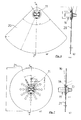
- FIG. 1 in the plan view of the wing of a wide-body aircraft, the wing shape and other details in this case correspond to the wing of the Airbus A 340-300. It can be seen at a distance from the front and rear wing edges of a beginning of the fuselage and reaching almost to the top of the wing field, which is outlined by a dashed line 8, which framed the area that may be entered during maintenance usually while outside of this dashed line lying areas should not be entered if possible.
- a safety rope 2 is fastened between a first attachment point 3 on the fuselage 4 of the aircraft and at a further attachment point 5 in the vicinity of the tip of the support surface 1.
- the tensioning device 7 In the vicinity of the attachment point 3 on the fuselage 4, the tensioning device 7 according to the invention is integrated into the cable 2, while a damping device is effectively realized by the rope 2 showing a specific force-expansion behavior and an expansion between 0.5 and 1.5%. per kN tensile stress having.
- This rope tensioning device can either be a mechanical tensioning device which operates with a spring, an electromechanical tensioning device which has an electromagnetic winding drive or else a hydraulic or pneumatic device which likewise has a corresponding winding drive.
- the tensioning device could in these cases also be used as a damping device, wherein other damping devices and tensioning devices and combinations of different damping and tensioning devices are conceivable, which are known in principle in the prior art and in its detailed embodiment are not the subject of the present invention.
- the cable tensioning device may be adjustable or simply ensures a fixed bias, so that the cable 2 between the two attachment points or An providingdyaken 3, 5 taut.
- the maximum value of this bias should typically be on the order of 0.5 to 2 kN.
- the damping or extensibility of the rope is chosen so that the forces occurring in the event of a fall are below the limits for which the attachment points are designed on the fuselage or on the wing. For many corresponding types of aircraft, values below 6 kN tensile stress are in a safe range below the maximum permissible limits.
- the extensibility of the rope 2 is selected accordingly. If necessary, one can determine the occurring tensile stresses and the required damping properties of the ropes or a separate damping device by simple drop tests with a weight, since these values of the total length of the safety rope, between one of the stop end points and an intervening anchoring freely stretched rope length and the maximum hedged Hang the drop height.
- a 0.5 kN biased safety rope with a load elongation of 1% per kN at a about 30 m long wing and a correspondingly long safety rope with an additional vacuum anchor approximately in the middle between the An anbigdyaken has proven to be a Protect the person against a fall from a height of approximately 3.5 m without exceeding the limit values of the tensile load at the lifting points.
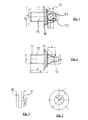
- FIG. 2 shows a side view of a threaded bolt 11 with a threaded portion 15 having a nominal diameter of three quarters of an inch.
- This threaded bolt already has integrated washers 16 and a cable eye 12 at its head end.
- the cable eye 12 is formed by a more or less U-shaped bracket 13 with a nearly rectangular cross section, which is integrally connected to a head plate of the threaded bolt and defines a circular opening with a sufficiently large radius to a safety rope 2, a cable eye or another To be able to pass holding element at the end of the rope.
- the clear diameter of the cable eye is about 12mm.
- FIG. 3 shows the same safety pin 11, however, in a rotated about its axis by 90 ° position, so that in this position the eyelet forming, U-shaped bracket 13 (partially hidden and dashed) is recognizable only as a rectangle from its outside.
- integrated washer 16 and (better recognizable in the drawing of the detail B in FIG. 2 according to FIG. 4 ) A circumferential groove, which serves to receive a large-scale shim.
- FIG. 5 shows a further washer of an elastomeric material whose diameter is approximately equal to that of the integrated washer 16 and whose inner diameter is dimensioned so that it can be moved over the threaded portion 15 away.
- FIG. 6a shows the bolt 11 in a plan view of the head together with an underneath, circular sector-shaped shim 20 which includes a 90 ° sector of a circle with a radius of about 200mm.
- the sectional view again containing the axis of the bolt according to FIG. 6b shows the arrangement of the shim 20 in a circumferential groove 18 on the head of the securing bolt 11 below the outer attachment eye 12 but still above the integrated washer 16, which, apart from the underlying elastomeric washer 18, with the fuselage or the wing in engagement occurs.
- the area of the circular sector-shaped, extensive Unterlegplatte is about 300cm 2 .
- Figure 7a shows again the plan view of a bolt with another large-area Unterlegplatte 21, which is circular in this case and has a diameter of about 200mm.
- the sectional view according to FIG. 7b shows the shim 21 in the same groove 17 of a threaded bolt 11 as in the case of the circular sector-shaped shim according to FIG. 6b ,
- These large-area shims serve primarily to protect the surface of the wing and hull in the vicinity of the attachment points, for example when attaching the bolts, when hooking a snap hook or when handling tools at the anchor point. At the same time, however, these shims also serve as a warning for the fact that the locking pins are still screwed into the corresponding threaded sleeves at the attachment points, even if, for example, the rope and any vacuum anchor have been removed from the wing.
- the safety rope itself is preferably constructed so as to have a cable core which absorbs tensile forces and a cable sheath which protects the core, which protects the cable against abrasion, contamination and irradiation and at the same time also provides a soft and smooth surface with a good feel.
- the rope preferably has only an elastic elongation and, in particular in the prestressed state, a maximum load elongation of 1.5% per kN, preferably about 1% per kN. Assuming the above-mentioned preferred values for bias and load limit of the damper, the force may vary from the bias (0.5 kN) to a limit of z. B.
- the breaking load of the rope in the preferred embodiment of the invention should be above 6 kN, in particular above 8 or 10 kN.
- the preferred ropes generally have a rope sheath of parallel strands or fibers extending substantially in the longitudinal direction of the rope, in contrast to twisted or braided rope cores, which may have a significantly greater elongation under load.
- the bias also ensures that the generally larger initial strain of such a rope is already compensated when the rope is stretched between the An anadyaken and biased by the tensioning device.
Abstract
Description
Die vorliegende Erfindung betrifft eine Vorrichtung zur Sicherung von Personen bei Wartungsarbeiten auf Flugzeugtragflächen, mit einem oberhalb der Tragfläche gespannten Seil.The present invention relates to a device for securing persons during maintenance work on aircraft wings, with a tensioned above the wing rope.
Flugzeugtragflächen müssen regelmäßig gewartet und zum Erhalt ihrer aerodynamischen Eigenschaften regelmäßig in relativ kurzen Zeitabständen gründlich gereinigt werden. Die Tragflächen von Passagierflugzeugen sind dabei üblicherweise so ausgelegt, dass sie bestimmte Zonen aufweisen, die von dem Wartungspersonal betreten werden dürfen, während andere Bereiche nach Möglichkeit nicht betreten werden sollen, um nicht die Tragfläche oder darunter liegende Strukturen zu beschädigen.Aircraft wings must be regularly maintained and thoroughly cleaned at relatively short intervals to maintain their aerodynamic properties. The wings of passenger aircraft are usually designed so that they have certain zones that may be entered by the maintenance personnel, while other areas should not be entered if possible, so as not to damage the wing or underlying structures.
Da moderne Passagierflugzeuge in der Regel relativ groß sind, befinden sich deren Tragflächen typischerweise in einem Abstand zum Erdboden, der drei Meter und mehr betragen kann. Jegliche Reinigungs- und sonstige Wartungsarbeiten auf den Tragflächen dürfen daher entsprechend den einschlägigen Sicherheitsvorschriften nur mit einer ausreichenden Absicherung der auf den Tragflächen arbeitenden Personen durch eine entsprechende Vorrichtung zur Absturzsicherung durchgeführt werden.Since modern passenger aircraft are usually relatively large, their wings are typically located at a distance to the ground, which can be three meters and more. Any cleaning and other maintenance work on the wings may therefore be carried out in accordance with the relevant safety regulations only with adequate protection of persons working on the wings by a corresponding device for fall protection.
Die Tragflächen moderner Passagierjets haben dabei zum Teil eine Länge von dreißig Metern und mehr, wobei die Vorrichtung zur Sicherung der Personen über diese gesamte Länge hinweg gleichermaßen funktionsfähig sein muss.The wings of modern passenger jets have in some cases a length of thirty meters and more, the device must be equally functional for securing the people over this entire length.
Es ist auch bereits eine entsprechende Vorrichtung zur Sicherung von Personen bei Wartungsarbeiten auf Flugzeugtragflächen bekannt, welche mehrere und typischerweise bis zu sechs Vakuumhalteeinrichtungen verwendet, die in etwa regelmäßigen Abständen auf die Oberseite der Flugzeugtragfläche aufgesetzt werden und durch Erzeugung von Unterdruck an ihrer Unterseite auf der Oberfläche der Tragfläche haften. Es versteht sich, dass derartige Vakuumhalteeinrichtungen zur Erzeugung der erforderlichen Haltekraft, die ausreichen muss, um eine über eine Sicherungsleine gesicherte Person, die über den Rand der Tragfläche abstürzt, aufzufangen, eine relativ große Ansaugfläche benötigen, um sicher an der Tragfläche zu haften und um auch die Tragflächenstruktur nicht nur punktuell zu belasten. Demzufolge haben die einzelnen Vakuumhalteeinrichtungen nicht nur eine entsprechend große Fläche, die nach dem Aufsetzen der Halteeinrichtung für die Wartungsarbeiten nicht mehr zugänglich ist, sondern es muss auch eine größere Zahl entsprechender Vakuumhalteeinrichtungen entlang der Oberfläche der Tragfläche angeordnet werden, wobei ein Sicherungsseil sämtliche Vakuumhalteeinrichtungen miteinander verbindet und Sicherungsleinen jeder einzelnen Person ihrerseits an dem Seil gesichert und geführt sind.There is already known a corresponding device for securing persons in maintenance work on aircraft wings, which uses several and typically up to six vacuum holding devices, which are placed at approximately regular intervals on the top of the aircraft wing and by generating negative pressure on its underside on the surface adhere to the wing. It will be appreciated that such vacuum retaining means for generating the required holding force sufficient to catch a person secured by a safety line falling over the edge of the support surface require a relatively large suction area to securely adhere and to the support surface also not to puncture the wing structure punctually. As a result, the individual Vacuum holding devices not only a correspondingly large area, which is no longer accessible after placing the holding device for the maintenance, but it must also a greater number of corresponding vacuum holding devices along the surface of the support surface are arranged, with a safety rope all vacuum holding devices together and safety lines of each Person in turn secured to the rope and guided.
Die Besetzung gewisser Flächen durch die Vakuumhalteeinrichtungen erfordert nicht nur, dass diese Vakuumhalteeinrichtungen während der Durchführung der Wartungsarbeiten und insbesondere während der Durchführung von Reinigungsarbeiten zwischenzeitlich gelöst und versetzt werden müssen, damit auch die zunächst von den Vakuumhalteeinrichtungen besetzten Flächen zugänglich werden, sondern diese Vakuumhalteeinrichtungen sind darüber hinaus auch relativ aufwändig und teuer und sie benötigen eine permanente Energiezufuhr.The occupation of certain surfaces by the vacuum holding devices not only requires that these vacuum holding devices must be temporarily released and displaced while carrying out the maintenance work and in particular during the execution of cleaning work, so that the first occupied by the vacuum holding devices surfaces are accessible, but these vacuum holding devices are above In addition, relatively complex and expensive and they require a permanent supply of energy.
Andererseits weisen zwar sowohl Tragflächen in der Nähe ihrer Enden als auch die Rümpfe von Flugzeugen oberhalb der jeweiligen Tragfläche zumindest bei der Airbusfamilie Verankerungs-. bzw. Anschlagspunkte auf, an denen ein Sicherungsseil befestigt werden könnte.On the other hand, although both wings in the vicinity of their ends and the hulls of aircraft above the respective wing anchoring at least in the Airbusfamilie. or stop points on which a safety rope could be attached.
Es hat sich allerdings herausgestellt, dass beim Spannen eines Seils zwischen dem Anschlagpunkt am Rumpf eines Flugzeuges und einem weiteren Anschlagpunkt in der Nähe der Tragflächenspitze die im Falle des Absturzes einer daran gesicherten Person auftretenden Kräfte größer sind als die Grenzbelastungen, für welche derartige Anschlagpunkte ausgelegt sind. Es ist deshalb nicht möglich, ein zwischen derartigen Anschlagendpunkten gespanntes Seil ohne weiteres als Vorrichtung zur Sicherung von Personen bei Wartungsarbeiten zu verwenden.However, it has been found that when tensioning a rope between the attachment point on the fuselage of an aircraft and another attachment point near the wing tip occurring in the event of the fall of a secured person forces are greater than the limit loads for which such attachment points are designed , It is therefore not possible to use a tensioned between such stop end points rope readily as a device for securing persons during maintenance.
Gegenüber diesem Stand der Technik liegt der vorliegenden Erfindung die Aufgabe zu Grunde, eine entsprechende Vorrichtung zu schaffen bzw. in der Weise auszugestalten, dass sie einerseits wesentlich einfacher und preiswerter wird als die bekannte Vakuumhalteeinrichtung, wobei andererseits aber auch unter keinen Umständen die von der Vorrichtung beanspruchten Flugzeugstrukturen über die zulässigen Grenzwerte hinaus belastet werden.Compared to this prior art, the present invention, the object of the invention to provide a corresponding device or in such a way that on the one hand much easier and cheaper than the known vacuum holding device, on the other hand, but on no account that of the device claimed aircraft structures are loaded beyond the permissible limits.
Diese Aufgabe wird dadurch gelöst, dass das Seil zwischen einem definierten ersten Anschlagpunkt am Rumpf oberhalb der Tragfläche und einem zweiten definierten Anschlagpunkt an der Oberseite der Tragfläche in der Nähe der Tragflächenspitze gespannt ist, wobei zwischen diesen beiden Anschlagpunkten eine Dämpfungseinrichtung vorgesehen ist, welche bei in dem Seil auftretenden Zugkräften eine definierte Seilverlängerung bewirkt.This object is achieved in that the rope is stretched between a defined first attachment point on the fuselage above the support surface and a second defined attachment point on the upper side of the support surface in the vicinity of the wing tip, wherein a damping device is provided between these two attachment points, which at in the rope tensile forces causes a defined rope extension.
Es hat sich herausgestellt, dass es mit einer solchen Dämpfungseinrichtung möglich ist, die in dem Seil auftretenden Kräfte, die von einer an dem Seil gesicherten Person, welche über eine zusätzliche persönliche Schutzausrüstung (auch kurz als PSA bezeichnet) möglicherweise ausgeübt werden, wenn diese Person über eine Kante der Tragfläche abstürzt, durch die Dämpfungseinrichtung soweit begrenzt werden können, dass die Belastungsgrenzwerte in den Anschlagpunkten nicht überschritten werden. Dabei muß zwar die Dämpfungseinrichtung ein gewisses Maß an effektiver Seilverlängerung bewirken, welches aber in der Praxis ohne weiteres so begrenzt werden kann, dass die Funktion des Seiles als Absturzsicherung nicht beeinträchtigt wird und dennoch die Grenzbelastungswerte der Anschlagpunkte nicht überschritten werden. Die PSA umfaßt ihrerseits i.a. eine Sicherungsleine, welche wiederum mit dem Seil verbunden ist.It has been found that it is possible with such a damping device, the forces occurring in the rope, which may be exercised by a person secured to the rope, which may be an additional personal protective equipment (also referred to as PSA for short), if that person crashes over an edge of the wing, can be limited by the damping device so far that the load limits are not exceeded in the attachment points. Although the damping device must cause a certain degree of effective cable extension, but which in practice can be readily limited so that the function of the rope is not impaired as fall protection and yet the limit load values of the attachment points are not exceeded. The PSA in turn comprises i.a. a safety line, which in turn is connected to the rope.
Gegebenenfalls wird bei sehr langen Tragflächen ein zusätzlicher Ankerpunkt etwa in der Mitte zwischen den Anschlagpunkten (Endpunkten) der Sicherungsleine gesetzt, wobei ein solcher Ankerpunkt eine herkömmliche Vakuumhalteeinrichtung sein kann.Optionally, for very long wings an additional anchor point is placed approximately in the middle between the attachment points (end points) of the security line, wherein such an anchor point may be a conventional vacuum holding device.
Zweckmäßigerweise ist die Dämpfungseinrichtung in das Seil integriert, indem ein Seil mit einem bestimmten Kraft-Dehnungsverhalten ausgewählt wird, das in der Weise ausgewählt wird, daß eine von einer Tragfläche abstürzende Person (bzw. ein abstürzendes Gewicht von z. B. 100 Kg) beim Abfangen eine Kraft in dem Seil hervorruft, die in der Spitze einen Wert von z. B. 4 kN nicht überschreitet.Conveniently, the damping device is integrated into the cable by selecting a cable with a certain force-elongation behavior, which is selected in such a way that a person falling from a wing (or a falling weight of, for example, 100 kg) Interception causes a force in the rope, the value in the top of z. B. 4 kN does not exceed.
Dieser Vorgang läuft in der Regel dynamisch ab, das heißt im Falle des Absturzes einer Person wird das Seil, an welchem die abstürzende Person über eine zusätzliche Sicherungsleine gesichert ist, seitlich ausgelenkt und es tritt eine Kraftspitze auf, wenn sich nach einem bestimmten Fallweg der Person die Sicherungsleine spannt, wobei das Seil dabei senkrecht zu seiner Spannrichtung zwischen den Anschlagpunkten ausgelenkt wird und dadurch die Spannung in dem Seil sich drastisch erhöht. Mit zunehmender Kraft verlängert sich jedoch das Seil in einem solchen Umfang, daß die eben angesprochenen Kraftgrenzwerte nicht überschritten werden. Alternativ kann man auch ein weniger dehnbares ("hartes") Seil in Kombination mit einer separaten Dämpfungsvorrichtung vorsehen, die in Abhängigkeit von den auftretenden Kraftgrenzwerten in begrenztem Umfang das Seil frei gibt, so dass es sich verlängern und dadurch die in dem Seil und den Anschlagpunkten ansonsten auftretende Kraftspitze abdämpfen kann. Dies hat gleichzeitig den Vorteil, dass auch die Kraft in der sich ruckartig spannenden Sicherungsleine, an welcher die gesicherte Person hängt, gedämpft wird. Erfindungsgemäß ist vorgesehen, daß die Seildehnung pro kN bei etwa 1 % liegt. Andererseits sollten aber auch gewisse Maximalwerte der Dehnungsfähigkeit nicht überschritten werden, weil ansonsten das Seil so sehr nachgeben könnte, daß eine abstürzende Person auf den Boden aufschlagen könnte. Gemäß einer Ausführungsform sollte daher der Wert der Dehnung 4% pro kN nicht übersteigen. Bevorzugte Werte der Lastdehnung (im linearen Bereich) liegen zwischen 0,5 und 2 %/kN, insbesondere zwischen 0,8 und 1,2 %/kNThis process is usually dynamic, that is, in the case of a person's fall, the rope to which the person who crashes is secured by an additional safety line, laterally deflected and there is a force peak when, after a certain fall of the person tensions the safety line, the cable is thereby deflected perpendicular to its clamping direction between the attachment points, thereby increasing the tension in the rope drastically. As the force increases, however, the cable lengthens to such an extent that the above-mentioned force limits are not exceeded. Alternatively, one may also provide a less ductile ("hard") rope in combination with a separate damping device which, depending on the force limits encountered, will release the rope to a limited extent so that it will lengthen and thereby extend the rope and anchor points otherwise occurring force peak can dampen. This also has the advantage that the force in the jerky exciting safety line to which the secured person hangs, is attenuated. According to the invention it is provided that the rope elongation per kN is about 1%. On the other hand, there should also be certain maximum values The extensibility should not be exceeded, because otherwise the rope could yield so much that a person falling could strike the ground. Thus, according to one embodiment, the value of the elongation should not exceed 4% per kN. Preferred values of load elongation (in the linear range) are between 0.5 and 2% / kN, in particular between 0.8 and 1.2% / kN
Im Fall einer separaten Dämpfungseinrichtung gibt diese eine zusätzliche Seillänge zweckmäßigerweise nur bei Auftreten eines oberen Grenzwertes der Zugspannung frei, wobei dieser Grenzwert höchstens 6 kN beträgt. Gemäß einer Ausführungsform der Erfindung wird dieser Grenzwert nicht unter 4 kN eingestellt. Weiterhin ist gemäß einer Ausführungsform der vorliegenden Erfindung die Dämpfungseinrichtung derart ausgelegt, dass sie die zusätzliche Seilfreigabe stoppt, sobald die Zugspannung in dem Seil einen unteren Grenzwert unterschreitet. Gemäß einer Variante der Erfindung liegt dieser untere Grenzwert bei etwa 4 kN oder etwas darüber.In the case of a separate damping device, this expediently releases an additional cable length only if an upper limit value of the tensile stress occurs, this limit value being at most 6 kN. According to one embodiment of the invention, this limit is not set below 4 kN. Furthermore, according to one embodiment of the present invention, the damping device is designed such that it stops the additional cable release when the tension in the rope falls below a lower limit. According to a variant of the invention, this lower limit value is about 4 kN or slightly higher.
Des weiteren gibt es eine Ausführungsform der Erfindung, bei welcher außerdem zwischen den Anschlagspunkten eine Seilspannvorrichtung vorgesehen ist, welche in dem Seil eine (eventuell variabel einstellbare) Vorspannung einstellt. Gemäß einer Variante der Erfindung ist die Seilspannvorrichtung derart ausgelegt, dass sie die Seilspannung auf einen Wert zwischen 0,3 und 1 kN, zum Beispiel auf etwa 0,5 kN einstellt. Diese Seilspannvorrichtung sorgt dafür, daß das Seil jederzeit vorgespannt ist und zu keinem Zeitpunkt schlaff durchhängt. Letzteres würde für eine abstürzende Person einen zusätzlichen Fallweg bedeuten, bevor sich das Seil strafft und überhaupt Kraft auf die Dämpfungseinrichtung ausübt, wobei dann die erst spät einsetzende Dämpfungseinrichtung noch zusätzlich Seillänge freigibt, so daß die für die Person verbleibende Distanz zum Boden womöglich nicht mehr ausreichen würde, um einen Aufprall zu vermeiden, zumal durch die zusätzliche Fallstrecke dann auch noch mehr kinetische Energie durch die Dämpfungseinrichtung aufzufangen wäre. Eine Seilvorspannung ist insbesondere auch dann besonders hilfreich, wenn das Seil aufgrund seines Kraft-Dehnungsverhaltens eine integrierte Dämpfungseinrichtung umfaßt, da de Anfangsdehnung eines dehnbaren Seiles oftmals überproportional groß (z. B. über 4% pro kN) ist und diese zusätzliche Dehnung durch die Vorspanneinrichtung beseitigt wird.Furthermore, there is an embodiment of the invention, in which also between the stop points a cable tensioning device is provided, which sets in the rope (possibly variably adjustable) bias. According to a variant of the invention, the cable tensioning device is designed such that it sets the cable tension to a value between 0.3 and 1 kN, for example to about 0.5 kN. This rope tensioning device ensures that the rope is preloaded at all times and sags slack at any time. The latter would mean an additional fall path for a person who falls, before the rope tightens and exerts any force on the damping device, in which case the late-onset damping device additionally releases rope length, so that the distance to the ground remaining for the person may no longer be sufficient would, in order to avoid an impact, especially because of the additional fall distance then even more kinetic energy would be absorbed by the damping device. Cable prestressing is also particularly helpful if the cable, due to its force-expansion behavior, comprises an integrated damping device, since the initial elongation of a stretchable cable is often disproportionately large (eg over 4% per kN) and this additional elongation by the pretensioning device is eliminated.
Selbstverständlich ist es auch möglich, die Dämpfungseinrichtung und die Seilspannvorrichtung in einer einzigen Einrichtung zu integrieren, das heißt Seilspannvorrichtung und Dämpfungseinrichtung sind miteinander identisch bzw. als eine Einheit miteinander kombiniert.Of course, it is also possible to integrate the damping device and the cable tensioning device in a single device, that is, cable tensioning device and damping device are identical to each other or combined as a unit.
In Falle einer extrem langen Tragfläche ist von mehr als 20 m, so daß auch die Seillänge zwischen den Anschlagspunkten etwa zwanzig Meter oder mehr erreicht, kann ein zusätzlicher Vakuumanker etwa im mittleren Bereich zwischen den Anschlagendpunkten des gespannten Seils vorgesehen sein, welcher das gespannte Seil gegen übermäßige seitliche Auslenkungen sichert. Anderenfalls besteht bei sehr großen Seillängen die Gefahr, dass trotz einer erheblichen seitlichen Auslenkung etwa in der Mitte des Seiles die auftretende Spannkraft in dem Seil noch nicht so groß wird, das die Dämpfungseinrichtung auslösen würde oder aber die Seildehnung bei moderater Spannkraft eine zu große seitliche Auslenkung zulässt, was dann zu einem entsprechend tieferen Fall einer abstürzenden Person führen könnte, die entweder dadurch verletzt würde. Eine allzu große frei Länge des Sicherungsseiles könnte zu einem relativ späten Auslösen der Dämpfungseinrichtung führen, die dann zur Dämpfung der Kraftspitze womöglich so viel zusätzliche Seillänge freigeben bzw. eine entsprechend große Seildehnung bewirken würde, dass ein Aufschlagen der abstürzenden Person auf dem Boden nicht mehr sicher auszuschließen wäre.In the case of an extremely long wing is more than 20 m, so that the rope length between the attachment points reaches about twenty meters or more, an additional vacuum anchor may be provided approximately in the middle region between the Anschlagendpunkten the tensioned rope, which the tensioned rope against ensures excessive lateral deflections. Otherwise there is a risk with very long cable lengths that, despite a considerable lateral deflection approximately in the middle of the rope, the occurring tension in the rope is not so great that would trigger the damping device or the rope elongation at moderate tension too much lateral deflection which would then lead to a correspondingly deeper fall of a falling person, which would either be violated. An excessively large free length of the safety rope could lead to a relatively late release of the damping device, which would then release as much additional cable length for damping the force peak or would cause a correspondingly large rope elongation that a striking of the person crashing on the ground no longer safe would be ruled out.
Zwar bringt eine zusätzliche Vakuumhalteeinrichtung den erwähnten Nachteil mit sich, daß diese einen Teil der zu wartenden bzw. reinigenden Fläche abdeckt, jedoch handelt es sich dabei im Gegensatz zum Stand der Technik nur um eine einzige Vakuumhalteeinrichtung, so daß der Aufwand, diese einmal zu versetzen, vergleichsweise gering ist und auch die von den Vakuumhalteeinrichtungen ansonsten verursachten Kosten sind dann immer noch drastisch reduziert, wenn beispielsweise nur eine einzige anstatt 6 Vakuumhalteeinrichtungen benötigt wird und diese auch nur bei besonders großen Tragflächen einzusetzen wäre,Although an additional vacuum holding device involves the mentioned disadvantage that it covers a part of the surface to be serviced or cleaned, in contrast to the prior art, it is only a single vacuum holding device, so that the expense of displacing it once is comparatively low and the costs otherwise caused by the vacuum holding devices are then still drastically reduced if, for example, only a single instead of 6 vacuum holding devices is needed and this would also be used only for very large wings,
An den Anschlagpunkten ist gemäß einer Ausführungsform der Erfindung je ein dreiviertel Zoll - Gewinde vorgesehen, wobei diese Anschlagpunkte mit einem hierzu passenden Gewindebolzen versehen sind, der eine Seilöse aufweist, in die entweder eine Seilschlaufe eingelegt werden kann oder an welcher auch ein Karabinerhaken, der mit einem Ende des Seils fest verbunden ist, eingehängt werden könnte.According to one embodiment of the invention, a three-quarter inch thread is provided at the attachment points, these attachment points being provided with a matching threaded bolt which has a cable eye into which either a cable loop can be inserted or on which a snap hook can also be inserted one end of the rope is firmly attached, could be hung.
Derartige Anschlagpunkte sind, wenn sie mit tragenden Strukturelementen des Flugzeugs bzw. der Tragfläche fest verbunden sind, ausreichend, um die erforderlichen Zugkräfte aufzunehmen, die bei Einsatz der erfindungsgemäßen Dämpfungseinrichtung maximal auftreten können.Such attachment points are, if they are firmly connected to supporting structural elements of the aircraft or the wing, sufficient to absorb the required tensile forces that can occur when using the damping device according to the invention maximum.
Des weiteren ist gemäß einer Ausführungsform der Erfindung mindestens eine das Seil umgreifende Führungshülse vorgesehen, wobei diese Führungshülse für die Verbindung einer Sicherungsleine mit dem Seil ausgelegt ist. Üblicherweise bleiben derartige Führungshülse immer an dem Seil angeordnet und sie weisen z. B. eine Öse oder dergleichen auf, in welche ein Wartungstechniker das Ende seiner persönlichen Sicherungsleine z. B. mit Hilfe eines Karabinerhakens befestigen kann, wobei die Sicherungsleine wiederum mit einem Haltegeschirr verbunden ist, das den Körper der Person sicher umfaßt.Furthermore, according to one embodiment of the invention, at least one guide sleeve enclosing the cable is provided, this guide sleeve being designed for connecting a safety line to the cable. Usually, such guide sleeve always remain on arranged the rope and they have z. As an eyelet or the like, in which a maintenance technician the end of his personal security line z. B. can attach using a snap hook, the securing line is in turn connected to a holding harness that includes the body of the person safely.
Zweckmäßigerweise sind mindestens zwei derartige Führungshülsen vorgesehen, so daß mehrere Personen gleichzeitig auf der Tragfläche arbeiten können und dabei an dem Seil gesichert sind. Sofern ein entsprechender Vakuumhalter bzw. Vakuumanker beispielsweise in der Mitte zwischen den beiden Anschlagpunkten zusätzlich vorgesehen ist, sollte mindestens eine Führungshülse jeweils beiderseits des Vakuumankers vorgesehen sein, vorzugsweise sollten auf beiden Seiten des Vakuumankers mindestens je zwei Führungshülsen vorgesehen sein. Dies ist insbesondere dann zweckmäßig, wenn die Führungshülsen und der Vakuumanker so ausgelegt sind, daß die Führungshülsen nicht über den Vakuumanker hinweg bzw. an diesem vorbei bewegt werden können.Conveniently, at least two such guide sleeves are provided so that several people can work simultaneously on the wing and are secured to the rope. If a corresponding vacuum holder or vacuum anchor is provided, for example, in the middle between the two attachment points, at least one guide sleeve should be provided on both sides of the vacuum anchor, preferably at least two guide sleeves should be provided on both sides of the vacuum anchor. This is particularly useful when the guide sleeves and the vacuum anchor are designed so that the guide sleeves can not be moved over the vacuum anchor away or past this.
Weiterhin ist gemäß einer Ausführungsform der Erfindung vorgesehen, daß die mindestens eine Führungshülse eine Sicherheitsklemmvorrichtung aufweist, welche auch bei plötzlichen Längsverschiebungen der Führungshülse entlang des Seils ein Verklemmen der Führungshülse an dem Seil bewirkt. Derartige Klemmvorrichtungen können z. B. durch Trägheitssensoren oder Hebelmechanismen ausgelöst werden, die nicht nur auf eine schnelle und plötzliche Bewegung der Führungshülse, sondern auch auf einen sehr kleinen Winkel zwischen dem Seil und der über die Führungshülse an dem Seil befestigten Sicherungsleine ansprechen.Furthermore, according to one embodiment of the invention, it is provided that the at least one guide sleeve has a safety clamping device which causes jamming of the guide sleeve on the cable even in the case of sudden longitudinal displacements of the guide sleeve along the cable. Such clamping devices can, for. B. triggered by inertial sensors or lever mechanisms that respond not only to a quick and sudden movement of the guide sleeve, but also to a very small angle between the rope and the safety sleeve attached to the rope over the guide sleeve.
Unter den Gewindebolzen an den Anschlagpunkten sind gemäß einer Ausführungsform der Erfindung großflächige Unterlegplatten vorgesehen, deren Farbe sich deutlich von der Farbe der Tragfläche und des Rumpfes im Bereich der Anschlagpunkte abhebt. Durch derartig großflächige und farblich auffällige Unterlegplatten soll sichergestellt werden, daß nach Abschluß der Wartungsarbeiten die entsprechenden Gewindebolzen, die in die am Flugzeug fixierten Anschlagpunkte (in Form entsprechend in Tragfläche oder Rumpf versenkter Hülsen mit Innengewinde) eingeschraubt sind, auch wieder entfernt werden, wobei die großflächigen Unterlegplatten das Vorhandensein der Gewindebolzen auch in großem Abstand sichtbar machen, während die Gewindebolzen allein womöglich übersehen werden könnten.Under the threaded bolts at the attachment points large-area shims are provided according to an embodiment of the invention, the color of which stands out clearly from the color of the wing and the hull in the region of the attachment points. Such large-area and color-striking underlays to ensure that after completion of the maintenance, the corresponding threaded bolts, which are screwed into the plane fixed to the aircraft attachment points (in the form of corresponding sunken in wing or hull sleeves with internal thread) are removed again, the large-area shims make visible the presence of the threaded bolt even at a great distance, while the threaded bolts alone could possibly be overlooked.
Gemäß einer Ausführungsform beträgt die Fläche der Unterlegplatten jeweils mindestens 100cm2 und vorzugsweise jeweils mindestens 200cm2. Die Unterlegplatten können in der Draufsicht kreisförmig oder kreissektorförmig, wahlweise aber auch dreieckig, quadratisch oder in anderer Weise polygonal ausgebildet sein. Vorzugsweise werden sie in der Signalfarbe Rot oder Orange hergestellt, wobei unter Umständen auch andersfarbige Unterlegplatten verwendet werden können, wenn die Farbe der Tragfläche oder des Rumpfes keinen ausreichenden Kontrast zu roten oder orangefarbenen Unterlegplatten bieten.According to one embodiment, the area of the shim plates is at least 100 cm 2 and preferably at least 200 cm 2 each. The shims can in the plan view circular or circular sector-shaped, but optionally also triangular, square or be formed polygonal in another way. Preferably, they are made in the signal color red or orange, although it may be possible to use different colored shims, if the color of the wing or the hull does not provide sufficient contrast to red or orange shims.
Weitere Vorteile, Merkmale und Anwendungsmöglichkeiten der vorliegenden Erfindung werden deutlich anhand der folgenden Beschreibung einer bevorzugten Ausführungsform und der dazugehörigen Figuren. Es zeigen:
-
Figur 1 eine Draufsicht auf eine relativ lange Tragfläche eines vierstrahligen Großraumflugzeuges (Airbus A 340) mit einem zwischen Anschlagendpunkten gespannten Seil und einem zusätzlichen Vakuumanker -
Figur 2 -
Figur 3 eine gegenüberFigur 2 -
Figur 4 eine Detailansicht des Bereiches B inFigur 2 -
Figur 5 eine elastische Unterlegscheibe zum Aufschieben auf den Gewindeabschnitt des Bolzens. -
Figur 6a eine Draufsicht auf einen Sicherungsbolzen mit einer darunterliegenden Unterlegplatte -
Figur 6b eine Schnittansicht des Bolzens und der Unterlegplatte nachFigur 6a entsprechend der Schnittlinie AA, -
Figur 7a eine Draufsicht auf einen Sicherungsbolzen mit einer kreisförmigen Unterlegplatte und -
Figur 7b einen Schnitt durch den Bolzen und die Unterlegplatte nachFigur 7a entsprechend der Linie A-A inFigur 7a
-
FIG. 1 a plan view of a relatively long wing of a four-engine wide-body aircraft (Airbus A 340) with a tensioned between stop end points rope and an additional vacuum anchor -
FIG. 2 a side view of a screwed into the sleeve of an attachment point 1 securing bolt, -
FIG. 3 one oppositeFIG. 2 locking bolts rotated by 90 ° about its axis, -
FIG. 4 a detailed view of the area B inFIG. 2 -
FIG. 5 an elastic washer for sliding onto the threaded portion of the bolt. -
FIG. 6a a plan view of a safety bolt with an underlying shim -
FIG. 6b a sectional view of the bolt and the shim afterFIG. 6a according to the section line AA, -
Figure 7a a plan view of a safety bolt with a circular shim and -
FIG. 7b a section through the bolt and the shim afterFigure 7a according to the line AA inFigure 7a
Man erkennt in
In dem dargestellten Ausführungsbeispiel erkennt man etwa in der Mitte zwischen den Anschlagendpunkten 3, 5 noch einen zusätzlichen Vakuumanker 6, der durch Erzeugung von Vakuum an seiner Unterseite an der Oberfläche der Tragfläche haftet und der an seiner oberen Seite geeignete Führungsösen für die Durchführung des gespannten Seils aufweist. Diese Führungsösen können so ausgestaltet sein, daß das Seil in einem nicht gespanntem Zustand in die Führungsösen eingehängt werden kann, ohne daß man Karabinerhaken oder dergleichen verwenden muß.In the illustrated embodiment can be seen approximately in the middle between the Anschlagendpunkten 3, 5 nor an additional vacuum anchor 6, which adheres by generating vacuum on its underside on the surface of the support surface and on its upper side suitable guide eyelets for the implementation of the tensioned rope having. These guide eyelets can be designed so that the rope in a non-tensioned state in the Guide eyelets can be hung without having to use snap hook or the like.
Des weiteren erkennt man beiderseits des Vakuumankers 6 je zwei Führungshülsen 9, die ihrerseits Ösen aufweisen, an denen der Karabinerhaken einer Sicherungsleine eingehängt werden kann. Das Wartungs- bzw. Reinigungspersonal befestigt jeweils eine Sicherungsleine an der Öse einer Führungshülse 9 und kann sich dann parallel zu dem Seil 2 in Längsrichtung der Tragfläche bewegen, wobei die Führungshülse entlang des Seiles mitgleitet. Sofern die Führungshülse und die Ösen am Vakuumanker so gestaltet sind, daß die Führungshülsen nicht in dauerhaftem Eingriff mit dem Seil 2 über den Vakuumanker hinwegbewegt werden können, muß die betreffende Person nach Erreichen des Vakuumankers die Sicherungsleine von der Führungshülse lösen und mit einer anderen Sicherungshülse jenseits des Vakuumankers wieder verbinden, um auch den anderen Teil der Tragfläche zu erreichen. Aufgrund der Verwendung des Vakuumankers kann es im Übrigen geschehen, das der Verlauf des Seiles zwischen den Anschlagpunkten 3 und 5 nicht gradlinig ist, sondern im Bereich des Vakuumankers leicht abknickt, was aber an der grundsätzlichen Funktion der Erfindung nichts ändert.Furthermore, one recognizes on both sides of the vacuum anchor 6 two guide sleeves 9, which in turn have eyes on which the snap hook of a safety line can be hung. The maintenance or cleaning personnel fastened each a safety line to the eyelet of a guide sleeve 9 and can then move parallel to the
Details der Anschlagpunkte, bzw. der entsprechenden Befestigungsbolzen sind in den
Die Fläche der kreissektorförmigen, großflächigen Unterlegplatte beträgt ca. 300cm2.The area of the circular sector-shaped, extensive Unterlegplatte is about 300cm 2 .
Da aufgrund der Anordnung der Nut 17 der zwischen dieser Nut und dem Gewindeabschnitt 15 noch verbleibenden Teil des Kopfes, nämlich insbesondere die integrierte Unterlegscheibe 16 und die elastomere Unterlegscheibe 18 angeordnet sind, verbleibt noch ein gewisser Abstand zur Oberfläche von Tragfläche bzw. Rumpf, so daß auch die großflächigen Unterlegplatten 20 und 21 jeweils im Abstand von Rumpf bzw. Tragfläche angeordnet sind, wobei die kreisförmige Unterlegplatte 21 am Anschlagpunkt 5 der Tragfläche angebracht wird, während die kreissektorförmige Unterlegplatte 20 am Anschlagpunkt 3 des Rumpfes 4 des Flugzeuges angebracht wird.Since due to the arrangement of the
Diese großflächigen Unterlegplatten dienen in erster Linie als Schutz der Oberfläche von Tragfläche und Rumpf in der Umgebung der Anschlagpunkte, zum Beispiel beim Anbringen der Bolzen, beim Einhängen eines Karabinerhakens oder beim Hantieren mit Werkzeugen an dem Anschlagpunkt. Gleichzeitig dienen diese Unterlegplatten aber auch als Warnhinweis für die Tatsache, daß die Sicherungsbolzen noch in die entsprechenden Gewindehülsen an den Anschlagpunkten angeschraubt sind, auch wenn beispielsweise das Seil und ein etwaiger Vakuumanker von der Tragfläche entfernt wurden.These large-area shims serve primarily to protect the surface of the wing and hull in the vicinity of the attachment points, for example when attaching the bolts, when hooking a snap hook or when handling tools at the anchor point. At the same time, however, these shims also serve as a warning for the fact that the locking pins are still screwed into the corresponding threaded sleeves at the attachment points, even if, for example, the rope and any vacuum anchor have been removed from the wing.
Das Sicherungsseil selbst ist vorzugsweise so aufgebaut, daß es einen Zugkräfte aufnehmenden Seilkern und einen den Kern schützenden Seilmantel aufweist, der das Seil gegen Abrieb, Verschmutzung und Bestrahlung schützt und gleichzeitig auch eine weiche und glatte Oberfläche mit einer guten Haptik bietet. Das Seil hat vorzugsweise nur eine elastische Dehnung und insbesondere im vorgespannten Zustand eine maximale Lastdehnung von 1,5 % pro kN, vorzugsweise etwa 1 % pro kN. Geht man von den oben erwähnten bevorzugten Werten für Vorspannung und Lastgrenzwert der Dämpfungseinrichtung aus, so kann die Kraft von der Vorspannung (0,5 kN) bis zu einem Grenzwert von z. B. 4 kN Zugspannung in dem Seil ansteigen, so daß demzufolge bei Einhalten der vorstehend erwähnten Lastdehnung das Seil sich höchstens um 4 % dehnt was einer Längenänderung von 1,2 m entspricht. Wird ein zusätzlicher Vakuumanker vorgesehen, der in der Mitte zwischen den Anschlagpunkten angeordnet ist, so wird das Seil nur zwischen dem Vakuumanker und einem Anschlagpunkt ausgelenkt, wo es über eine Strecke von etwa 15 m frei gespannt ist. Die Längenänderung wird allein in diesem Abschnitt in eine seitliche Auslenkung umgesetzt. Dies ergibt eine maximale seitliche Auslenkung in der Mitte zwischen Anker und Anschlagpunkt von 3,05 m bei einem Auslenkungswinkel (gegenüber der geraden Seilerstreckung) von ca. 22,2°. Die auf eine abstürzende Person wirkende Lastspitze würde dann etwa 3 kN betragen, entsprechend etwa dem 3-fachen Körpergeweicht, wenn die Person einschließlich Ausrüstung etwa 100 Kg Gewicht hätte. Es versteht sich, daß leichtere Personen entsprechend früher abgebremst werden und die Auslenkung dann auch geringer ausfällt.The safety rope itself is preferably constructed so as to have a cable core which absorbs tensile forces and a cable sheath which protects the core, which protects the cable against abrasion, contamination and irradiation and at the same time also provides a soft and smooth surface with a good feel. The rope preferably has only an elastic elongation and, in particular in the prestressed state, a maximum load elongation of 1.5% per kN, preferably about 1% per kN. Assuming the above-mentioned preferred values for bias and load limit of the damper, the force may vary from the bias (0.5 kN) to a limit of z. B. 4 kN tensile stress in the rope rise, so that, if the above-mentioned load elongation, the rope stretches at most by 4% which corresponds to a change in length of 1.2 m. If an additional vacuum anchor is provided, which is located in the middle between the attachment points, the rope is deflected only between the vacuum anchor and a stop point, where it is freely stretched over a distance of about 15 m. The change in length is implemented in this section alone in a lateral deflection. This results in a maximum lateral deflection in the middle between anchor and anchor point of 3.05 m at a deflection angle (compared to the straight cable extension) of about 22.2 °. The load peak acting on a falling person would then be about 3 kN, corresponding to about 3 times the body weight, if the person including equipment had about 100 kg weight. It is understood that lighter persons are decelerated earlier and the deflection is then also lower.
Die Bruchlast des Seiles sollte in der bevorzugten Ausführungsform der Erfindung oberhalb von 6 kN, insbesondere oberhalb von 8 oder 10 kN liegen.The breaking load of the rope in the preferred embodiment of the invention should be above 6 kN, in particular above 8 or 10 kN.
Da das Seil bei Abstürzen nur als primäre Verankerung einer PSA dient und bei Abstürzen in der Regel senkrecht zur Seilerstreckung ausgelenkt wird, kommt es im Gegensatz zu üblichen Sicherungsleinen nicht so sehr darauf an, daß das Seil eine große Lastdehnung aufweist, da die Dehnung des Seiles durch die seitliche Auslenkung in eine in etwa zum Kehrwert des Sinus des Auslenkungswinkels proportionale Wegstrecke übersetzt wird, die der Absturztiefe entspricht. Auf die abstürzende Person wirkende Lastspitzen werden also schon durch die Geometrie der Anordnung erheblich gedämpft.Since the rope is used only as a primary anchorage of a PSA crashes and is deflected in crashes usually perpendicular to the cable extension, it comes in contrast to conventional safety lines not so much that the rope has a large load elongation, since the elongation of the rope by the lateral deflection in about the inverse of the sinus the displacement angle proportional distance is translated, which corresponds to the depth of fall. Thus, load peaks acting on the person who falls are considerably dampened by the geometry of the arrangement.
Die bevorzugten Seile haben im allgemeinen einen Seilmantel aus parallelen, im wesentlichen in Längsrichtung des Seiles verlaufenden Litzen oder Fasern, im Gegensatz zu gedrehten oder geflochtenen Seilkernen, die bei Belastung eine wesentlich größere Dehnung aufweisen können.The preferred ropes generally have a rope sheath of parallel strands or fibers extending substantially in the longitudinal direction of the rope, in contrast to twisted or braided rope cores, which may have a significantly greater elongation under load.
Die Vorspannung sorgt außerdem dafür, daß die im allgemeinen größere Anfangsdehnung eines solchen Seiles bereits kompensiert ist, wenn das Seil zwischen den Anschlagendpunkten gespannt und durch die Spannvorrichtung vorgespannt ist.The bias also ensures that the generally larger initial strain of such a rope is already compensated when the rope is stretched between the Anschlagendpunkten and biased by the tensioning device.
Claims (15)
Applications Claiming Priority (1)
| Application Number | Priority Date | Filing Date | Title |
|---|---|---|---|
| DE102008008577A DE102008008577A1 (en) | 2008-02-11 | 2008-02-11 | fall Protection |
Publications (2)
| Publication Number | Publication Date |
|---|---|
| EP2088079A2 true EP2088079A2 (en) | 2009-08-12 |
| EP2088079A3 EP2088079A3 (en) | 2012-12-26 |
Family
ID=40386442
Family Applications (1)
| Application Number | Title | Priority Date | Filing Date |
|---|---|---|---|
| EP09152077A Withdrawn EP2088079A3 (en) | 2008-02-11 | 2009-02-04 | Fall protection device |
Country Status (3)
| Country | Link |
|---|---|
| US (1) | US20100065370A1 (en) |
| EP (1) | EP2088079A3 (en) |
| DE (1) | DE102008008577A1 (en) |
Cited By (1)
| Publication number | Priority date | Publication date | Assignee | Title |
|---|---|---|---|---|
| CN113476758A (en) * | 2021-06-11 | 2021-10-08 | 中铁建工集团山东有限公司 | Anti-falling system for preventing collision and strengthening based on data monitoring |
Families Citing this family (4)
| Publication number | Priority date | Publication date | Assignee | Title |
|---|---|---|---|---|
| US9174073B2 (en) | 2013-02-08 | 2015-11-03 | D B Industries, Llc | Energy absorber assembly and components thereof |
| US9194633B2 (en) | 2013-03-15 | 2015-11-24 | Bp Corporation North America Inc. | Bolt with integrated gasket |
| US10926115B2 (en) * | 2016-09-26 | 2021-02-23 | The Boeing Company | Fall protection apparatus and method |
| US11130009B2 (en) * | 2016-11-04 | 2021-09-28 | Textron Innovations Inc. | Rotorcraft fall restraint protection attach points and mechanism systems |
Citations (4)
| Publication number | Priority date | Publication date | Assignee | Title |
|---|---|---|---|---|
| DE4035814A1 (en) * | 1990-11-10 | 1992-05-14 | Techtex Bremen Gmbh | Low stretch rope - has core of low stretch fibres and mantle with mixture of low strength and normal stretch fibres |
| GB2338506A (en) * | 1998-06-19 | 1999-12-22 | Latchways Plc | Safety line clamping device |
| US20020046902A1 (en) * | 2000-08-31 | 2002-04-25 | Choate Gary E. | Method to reduce horizontal lifeline tension and extension during fall arrest |
| US20060273600A1 (en) * | 2005-06-02 | 2006-12-07 | D B Industries, Inc. | Vacuum anchor |
Family Cites Families (10)
| Publication number | Priority date | Publication date | Assignee | Title |
|---|---|---|---|---|
| DE3023489C2 (en) * | 1980-06-24 | 1983-11-10 | Mittelmann & Co Armaturenwerk, 5603 Wülfrath | Fall protection device for people working on buildings |
| GB9823759D0 (en) * | 1998-10-31 | 1998-12-23 | Rota Limited | A safety device |
| FR2803761B1 (en) * | 2000-01-17 | 2002-03-29 | Rodolphe Argoud | ANTI-FALL DEVICE |
| WO2003027383A1 (en) * | 2001-09-25 | 2003-04-03 | Mammut Tec Ag | Rope-like structure |
| JP3801515B2 (en) * | 2002-02-15 | 2006-07-26 | 株式会社プロップ | Safety belt attachment and safety belt using the same |
| NZ547238A (en) * | 2003-10-14 | 2009-02-28 | Arvo Poldmaa | Anchor assembly for safety device |
| US20050098381A1 (en) * | 2003-10-23 | 2005-05-12 | Flaherty Brian J. | Roofing safety cable system and method |
| NL1027728C2 (en) * | 2003-12-24 | 2005-07-05 | Kedge Holding Bv | Safety device installed on roof of object e.g. house, comprises flexible fastening flap that extends laterally between flange portions, for firm and durable connection to object |
| US20060032703A1 (en) * | 2004-07-30 | 2006-02-16 | William Burdet | Fall restraint device |
| US20080035423A1 (en) * | 2006-08-08 | 2008-02-14 | D B Industries, Inc. | Retractable horizontal lifeline assembly |
-
2008
- 2008-02-11 DE DE102008008577A patent/DE102008008577A1/en not_active Ceased
-
2009
- 2009-02-04 EP EP09152077A patent/EP2088079A3/en not_active Withdrawn
- 2009-02-10 US US12/368,580 patent/US20100065370A1/en not_active Abandoned
Patent Citations (4)
| Publication number | Priority date | Publication date | Assignee | Title |
|---|---|---|---|---|
| DE4035814A1 (en) * | 1990-11-10 | 1992-05-14 | Techtex Bremen Gmbh | Low stretch rope - has core of low stretch fibres and mantle with mixture of low strength and normal stretch fibres |
| GB2338506A (en) * | 1998-06-19 | 1999-12-22 | Latchways Plc | Safety line clamping device |
| US20020046902A1 (en) * | 2000-08-31 | 2002-04-25 | Choate Gary E. | Method to reduce horizontal lifeline tension and extension during fall arrest |
| US20060273600A1 (en) * | 2005-06-02 | 2006-12-07 | D B Industries, Inc. | Vacuum anchor |
Cited By (1)
| Publication number | Priority date | Publication date | Assignee | Title |
|---|---|---|---|---|
| CN113476758A (en) * | 2021-06-11 | 2021-10-08 | 中铁建工集团山东有限公司 | Anti-falling system for preventing collision and strengthening based on data monitoring |
Also Published As
| Publication number | Publication date |
|---|---|
| DE102008008577A1 (en) | 2009-08-13 |
| EP2088079A3 (en) | 2012-12-26 |
| US20100065370A1 (en) | 2010-03-18 |
Similar Documents
| Publication | Publication Date | Title |
|---|---|---|
| EP2270354B1 (en) | Rope end anchor with overload prevention | |
| DE60204977T2 (en) | SAFETY ANCHORING DEVICE WITH A SHOCK ABSORBER | |
| AT11927U1 (en) | FALL PROTECTION | |
| EP2088079A2 (en) | Fall protection device | |
| DE202005011463U1 (en) | Fall prevention device for roof workers, comprises threaded rod anchored in roof and secured inside support tube | |
| AT506224B1 (en) | STOPPING DEVICE FOR FALLING SAFETY | |
| DE102018103565A1 (en) | Device for securing persons against falling | |
| EP3277577B1 (en) | Device for equalizing a pressure difference for an aircraft | |
| DE202012010035U1 (en) | Energy converter for safety lines and safety line with such a converter device | |
| DE202011001953U1 (en) | Load-bearing stop device | |
| DE2915516C2 (en) | Device for absorbing kinetic energy for scaffolding suspended from suspension ropes | |
| DE102010048243A1 (en) | Holding device for interior trim parts of an airframe and fastening system with such holding devices | |
| DE102011110848A1 (en) | Connection for safety fence panel on fence post or such component carrying safety fence panel, and for use in safety fencing machine, has strip-shaped connecting element, which has one end and opposite another end | |
| DE102012005079B4 (en) | Device for fall protection, in particular of persons located on elevated structures | |
| AT520447B1 (en) | fall Protection | |
| DE202011002081U1 (en) | separating element | |
| EP3162960B1 (en) | Cable brake assembly | |
| DE60030690T2 (en) | Shock-absorbing device | |
| DE102009038540B3 (en) | Hook for e.g. fall protection runner, in rope access work system, has damping element arranged at end of bolt between flange portion and head of bolt, where end of bolt is protruded outside and in inner region of hook body of portion | |
| DE202013104418U1 (en) | Facade console and facade construction | |
| EP2643257B1 (en) | Rope safety catch | |
| EP3192571B1 (en) | Component for a holding device for holding at least one cloth, holding device and sport device | |
| DE1850841U (en) | METAL, ESPECIALLY STEEL, BARRIER FOR CAR ROADS. | |
| DE202020102735U1 (en) | Functional element and machine guard | |
| EP4218948A1 (en) | Cable anchor for a cable holding device |
Legal Events
| Date | Code | Title | Description |
|---|---|---|---|
| PUAI | Public reference made under article 153(3) epc to a published international application that has entered the european phase |
Free format text: ORIGINAL CODE: 0009012 |
|
| AK | Designated contracting states |
Kind code of ref document: A2 Designated state(s): AT BE BG CH CY CZ DE DK EE ES FI FR GB GR HR HU IE IS IT LI LT LU LV MC MK MT NL NO PL PT RO SE SI SK TR |
|
| AX | Request for extension of the european patent |
Extension state: AL BA RS |
|
| PUAL | Search report despatched |
Free format text: ORIGINAL CODE: 0009013 |
|
| AK | Designated contracting states |
Kind code of ref document: A3 Designated state(s): AT BE BG CH CY CZ DE DK EE ES FI FR GB GR HR HU IE IS IT LI LT LU LV MC MK MT NL NO PL PT RO SE SI SK TR |
|
| AX | Request for extension of the european patent |
Extension state: AL BA RS |
|
| RIC1 | Information provided on ipc code assigned before grant |
Ipc: B64F 5/00 20060101AFI20121122BHEP Ipc: E04G 21/32 20060101ALI20121122BHEP |
|
| AKY | No designation fees paid | ||
| REG | Reference to a national code |
Ref country code: DE Ref legal event code: R108 |
|
| REG | Reference to a national code |
Ref country code: DE Ref legal event code: R108 Effective date: 20130904 |
|
| STAA | Information on the status of an ep patent application or granted ep patent |
Free format text: STATUS: THE APPLICATION IS DEEMED TO BE WITHDRAWN |
|
| 18D | Application deemed to be withdrawn |
Effective date: 20130627 |