EP2087229B1 - Starter zum andrehen einer brennkraftmaschine mit ritzelwellenabstützung - Google Patents
Starter zum andrehen einer brennkraftmaschine mit ritzelwellenabstützung Download PDFInfo
- Publication number
- EP2087229B1 EP2087229B1 EP07803176.2A EP07803176A EP2087229B1 EP 2087229 B1 EP2087229 B1 EP 2087229B1 EP 07803176 A EP07803176 A EP 07803176A EP 2087229 B1 EP2087229 B1 EP 2087229B1
- Authority
- EP
- European Patent Office
- Prior art keywords
- starter
- pinion
- pinion shaft
- shaft
- drive shaft
- Prior art date
- Legal status (The legal status is an assumption and is not a legal conclusion. Google has not performed a legal analysis and makes no representation as to the accuracy of the status listed.)
- Not-in-force
Links
Images


Classifications
-
- F—MECHANICAL ENGINEERING; LIGHTING; HEATING; WEAPONS; BLASTING
- F02—COMBUSTION ENGINES; HOT-GAS OR COMBUSTION-PRODUCT ENGINE PLANTS
- F02N—STARTING OF COMBUSTION ENGINES; STARTING AIDS FOR SUCH ENGINES, NOT OTHERWISE PROVIDED FOR
- F02N15/00—Other power-operated starting apparatus; Component parts, details, or accessories, not provided for in, or of interest apart from groups F02N5/00 - F02N13/00
- F02N15/02—Gearing between starting-engines and started engines; Engagement or disengagement thereof
- F02N15/04—Gearing between starting-engines and started engines; Engagement or disengagement thereof the gearing including disengaging toothed gears
- F02N15/06—Gearing between starting-engines and started engines; Engagement or disengagement thereof the gearing including disengaging toothed gears the toothed gears being moved by axial displacement
- F02N15/062—Starter drives
-
- F—MECHANICAL ENGINEERING; LIGHTING; HEATING; WEAPONS; BLASTING
- F02—COMBUSTION ENGINES; HOT-GAS OR COMBUSTION-PRODUCT ENGINE PLANTS
- F02N—STARTING OF COMBUSTION ENGINES; STARTING AIDS FOR SUCH ENGINES, NOT OTHERWISE PROVIDED FOR
- F02N15/00—Other power-operated starting apparatus; Component parts, details, or accessories, not provided for in, or of interest apart from groups F02N5/00 - F02N13/00
- F02N15/02—Gearing between starting-engines and started engines; Engagement or disengagement thereof
- F02N15/022—Gearing between starting-engines and started engines; Engagement or disengagement thereof the starter comprising an intermediate clutch
- F02N15/023—Gearing between starting-engines and started engines; Engagement or disengagement thereof the starter comprising an intermediate clutch of the overrunning type
-
- Y—GENERAL TAGGING OF NEW TECHNOLOGICAL DEVELOPMENTS; GENERAL TAGGING OF CROSS-SECTIONAL TECHNOLOGIES SPANNING OVER SEVERAL SECTIONS OF THE IPC; TECHNICAL SUBJECTS COVERED BY FORMER USPC CROSS-REFERENCE ART COLLECTIONS [XRACs] AND DIGESTS
- Y10—TECHNICAL SUBJECTS COVERED BY FORMER USPC
- Y10T—TECHNICAL SUBJECTS COVERED BY FORMER US CLASSIFICATION
- Y10T74/00—Machine element or mechanism
- Y10T74/13—Machine starters
- Y10T74/131—Automatic
- Y10T74/134—Clutch connection
Definitions
- the invention relates to a starter for starting an internal combustion engine according to the preamble of claim 1, and in particular a free-ejecting starter.
- ertrieb starters are often used, such as in Fig. 2 of the US-A-5 099 703 disclosed.
- These starters have an electric starter motor, the drive shaft drives a displaceable in a housing of the starter in the axial direction pinion shaft, which carries a pinion outside of the housing.
- the drive shaft has an external toothing in the form of a helical thread, which meshes with a complementary internal toothing of a sliding together with the pinion shaft coupling part of a roller overrunning clutch between the drive shaft and the pinion shaft.
- the roller overrunning clutch prevents after starting the internal combustion engine that the starter motor is driven by the internal combustion engine at a high speed and thereby damaged.
- the starter is turned on, after which the pinion is meshed in a gear or a ring gear of the internal combustion engine by a Einspurmechanismus the starter moves the pinion shaft together with the coupling part of the overrunning clutch from an off or rest position of the pinion in a Einspur ein, in the pinion is meshed with the gear or the ring gear internal combustion engine and meshes with it.
- the overrunning clutch and the pinion shaft to put the gear or the ring gear of the internal combustion engine in rotation, act in the region of the pinion large reaction forces on the pinion shaft.
- the pinion shaft While the pinion shaft is supported and supported in the so-called Maulstartern both sides of the pinion and can hardly be deflected by the radial forces acting on the pinion, the pinion shaft in the so-called free-ejecting starters only on one side of the pinion, namely within the housing of the starter stored , At a deflection of Pinion shaft due to the radial forces applied to the pinion, the pinion shaft in this case expediently supported on the drive shaft via a bush arranged between the drive shaft and the hollow pinion shaft.
- the FR-A-2 681 911 discloses a starter with a displaceable on a motor shaft of a starter motor hollow pinion shaft, which is displaceable for meshing the pinion from the starter motor in a Einspurwolf.
- the pinion shaft is braced on the motor shaft via two shaft bearings that can be displaced together with the pinion shaft along the motor shaft, but does not extend to the vicinity of the external toothing of the motor shaft in the single-track position.
- the present invention seeks to improve a starter of the type mentioned and in particular a free-ejecting starter to the effect that the roller races of the overrunning clutch are less heavily loaded by the radial forces acting on the pinion shaft during cranking of the internal combustion engine.
- a device for supporting the pinion shaft in the Einspur ein on a side remote from the starter motor end portion of the outer toothing of the drive shaft By this measure, the pinion shaft can be supported in the Einspur ein additionally in the region of its end facing away from the pinion front end directly on the drive shaft when it is deflected slightly due to the force exerted on the pinion radial forces. In this way, the forces required to support the pinion shaft can be completely introduced bypassing the rollers of the overrunning clutch in the drive shaft.
- the invention is based on the idea to maintain an existing in the off or rest position of the pinion shaft overlap between the pinion shaft and the outer teeth of the drive shaft until reaching the Einspur ein, so that in this position, the pinion shaft supported in the overlapping region on the outer toothing of the drive shaft can.
- the overlap between the pinion shaft and the outer teeth of the drive shaft in the off and rest position is also present, but it is not large enough so that it is already lost quite a bit before reaching the Einspurwolf.
- the support means comprises a socket whose front end facing the starter motor overlaps the outer toothing or a front, the pinion facing portion of the outer toothing.
- the degree of overlap in the Einspur ein is more than 1.5 mm, to provide sufficient support of the pinion shaft on the external teeth, but on the other hand expediently less than 3 mm in order to avoid a customer not desired increase in the length of the starter ,
- the bush is formed as a unit with the pinion shaft and forms a starter motor facing hollow end portion of the pinion shaft.
- the sleeve separate from the pinion shaft and rotatably connect to this before mounting the pinion shaft with this, for example by pressing the bushing into a corresponding bore of the pinion shaft.
- the bush expediently projects with radial clearance in an opposite bore of the drive shaft driven by the coupling part of the overrunning clutch.
- the overlapping in the Einspurwolf with the sleeve or the pinion shaft portion of the formed as a coarse thread outer teeth of the drive shaft is not required for transmitting the rotation of the drive shaft on the coupling part of the one-way clutch and therefore may advantageously have a larger tip diameter than an adjacent, with the Female thread of the coupling part meshing portion of the external toothing, so that in the overlap region a very small radial play of about 0.1 to 0.15 mm can be set, which ensures in the case of a deflection of the pinion shaft for rapid support of the same on the outer toothing of the drive shaft.
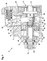
- the only partially shown in the drawing freely ejecting lenttrieb starter 2 for an internal combustion engine consists in a conventional manner of a starter housing 4, housed in a starter housing 4 starter motor 6 (only partially visible), the armature 8 rotatably with an armature - or drive shaft 10th is connected, one of a freewheel clutch 12 driven by the drive shaft 10, mounted on a roller bearing 14 in the starter housing 4 pinion shaft 16 which carries a pinion 20 at its free end 18 outside of the starter housing 4, and a Einspurmechanismus 22 for meshing the pinion 20 in a gear or a ring gear (not shown) of the internal combustion engine.
- the meshing mechanism 22 includes an engagement relay 26 disposed above a pole housing 24 of the starter motor 6 and an engagement lever 30 disposed between the engagement relay 26 and a clutch member 28 of the one-way clutch 12.
- the engagement lever 30 can be pivoted clockwise about a pivot bearing 32 by energizing the engagement relay 26, around the coupling part 28 of the one-way clutch 12 together with the pinion shaft 16 and the pinion 20 from a in Fig. 1 illustrated off or rest position of the starter 2 with respect to the drive shaft 10 in the axial direction to the left in an in Fig. 2 shown Einspurwolf to move, in which the pinion 20 is meshed with the gear or the ring gear of the internal combustion engine and meshes with this to turn the engine by power to the starter motor 6 and start.
- the drive shaft 10 protrudes with its front end 30 facing away from the starter motor 6 into a stepped bore 32 of the pinion shaft 16 which is open toward the starter motor 6. Between the front end 30, which is in the off or inactive position of the pinion shaft 16 (FIG. Fig. 1 ) is completely immersed in a portion 34 of the stepped bore 32 with a smaller diameter, and a mounted in a pivot bearing 36 of a front bearing plate 38 of the pole housing 24 cylindrical portion 40, the drive shaft 10 is provided with an external toothing. This external toothing consists of two in the axial direction of the drive shaft 10 successively arranged coarse thread sections 42, 44 with different numbers of teeth.
- the teeth of the two helical sections 42, 44 have the same thread pitch in the illustrated embodiment, but this need not necessarily be the case.
- the front, facing away from the starter motor 6 helical section 42 of the drive shaft 10 has a smaller number of teeth and a shorter axial extent than the rear, the starter motor 6 adjacent helical section 44th
- the overrunning clutch 12 has a plurality of clutch rollers 50, which between an inner roller track 52 on the outer peripheral surface of the starter motor 8 facing, enlarged in diameter portion of Pinion shaft 16 and an outer roller race 54 are arranged on the inner circumference of the driver portion 48 of cup-shaped enlarged portion 56 of the coupling part 28 and provide when turning the engine for a transmission of rotation of the coupling part 28 on the pinion shaft 16, but one of the rotation of the Pinion 16 enable independent rotation of the drive shaft 10, as soon as the speed of the after starting the internal combustion engine driven by this pinion shaft 16 exceeds the speed of the drive shaft 10 of the starter motor 6.
- pinion shaft 16 has an integral extension sleeve 60, which projects so far in the direction of the starter motor 6 via the provided with the roller track 52 portion of the pinion shaft 16, that their free front end overlaps in the Einspur ein by a few millimeters with the front helical section 42 and can be supported on this when the pinion 20 is loaded with the force F.
- a very small radial clearance of about 0.1 to 0.15 mm between a tip circle diameter of the front helical thread portion 42 and a cylindrical inner periphery of the extension sleeve 60 is provided.
- the clearance between the inner circumference of the extension sleeve 60 and the tip diameter of the rear helical thread portion 44 is about 0.5 to 0.7 mm when in the off or inoperative position (FIG. Fig. 1 ) of the pinion shaft 16 and during the axial displacement of the pinion shaft 16 in the Einspur ein ( Fig. 2 ) is located within the extension sleeve 60.
- the extension sleeve 60 projects with play into a stepped bore 62 of the coupling part 28 so that it can rotate in free-running with respect to the pinion shaft 16.
Landscapes
- Engineering & Computer Science (AREA)
- Chemical & Material Sciences (AREA)
- Combustion & Propulsion (AREA)
- Mechanical Engineering (AREA)
- General Engineering & Computer Science (AREA)
- Connection Of Motors, Electrical Generators, Mechanical Devices, And The Like (AREA)
- Gear Transmission (AREA)
Description
- Die Erfindung betrifft einen Starter zum Andrehen einer Brennkraftmaschine gemäß dem Oberbegriff des Anspruchs 1, und insbesondere einen freiausstoßenden Starter.
- Als elektrische Starter zum Andrehen einer Brennkraftmaschine werden häufig sogenannte Schraubtrieb-Starter eingesetzt, wie zum Beispiel in
Fig. 2 derUS-A- 5 099 703 offenbart. Diese Starter weisen einen elektrischen Startermotor auf, dessen Antriebswelle eine in einem Gehäuse des Starters in axialer Richtung verschiebbare Ritzelwelle treibt, die außerhalb des Gehäuses ein Ritzel trägt. Die Antriebswelle weist eine Außenverzahnung in Form eines Steilgewindes auf, die mit einer komplementären Innenverzahnung eines zusammen mit der Ritzelwelle verschiebbaren Kupplungsteils einer Rollen-Freilaufkupplung zwischen der Antriebswelle und der Ritzelwelle kämmt. Die Rollen-Freilaufkupplung verhindert nach dem Andrehen der Brennkraftmaschine, dass der Startermotor von der Brennkraftmaschine mit einer zu hohen Geschwindigkeit angetrieben und dadurch beschädigt wird. Zum Starten der Brennkraftmaschine wird der Starter eingeschaltet, woraufhin das Ritzel in ein Zahnrad oder einen Zahnkranz der Brennkraftmaschine eingespurt wird, indem ein Einspurmechanismus des Starters die Ritzelwelle zusammen mit dem Kupplungsteil der Freilaufkupplung aus einer Aus - oder Ruhestellung des Ritzels in eine Einspurstellung verschiebt, in der das Ritzel in das Zahnrad oder den Zahnkranz Brennkraftmaschine eingespurt ist und mit diesem kämmt. Wenn das Ritzel in der Einspurstellung vom Startermotor über die Antriebswelle, die Freilaufkupplung und die Ritzelwelle angetrieben wird, um das Zahnrad oder den Zahnkranz der Brennkraftmaschine in Drehung zu versetzen, wirken im Bereich des Ritzels große Reaktionskräfte auf die Ritzelwelle ein. - Während die Ritzelwelle bei den sogenannten Maulstartern beiderseits des Ritzels gelagert und abgestützt ist und von den auf das Ritzel einwirkenden Radialkräften kaum ausgelenkt werden kann, ist die Ritzelwelle bei den sogenannten freiausstoßenden Startern nur auf einer Seite des Ritzels, nämlich innerhalb des Gehäuses des Starters, gelagert. Bei einer Auslenkung der Ritzelwelle infolge der auf das Ritzel aufgebrachten Radialkräfte stützt sich die Ritzelwelle in diesem Fall zweckmäßig über eine zwischen der Antriebswelle und der hohlen Ritzelwelle angeordnete Buchse auf der Antriebswelle ab. Je nach Toleranzlage der Spiele im Lager und in der Buchse wird jedoch zumeist auch ein Teil der Kräfte über die Rollen der Freilaufkupplung in den Kupplungsteil und von diesem über die im Eingriff stehenden Verzahnungen des Kupplungsteils und der Antriebswelle in die letztere eingeleitet. Dadurch werden die an der Ritzelwelle bzw. am Kupplungsteil ausgebildeten gegenüberliegenden Laufbahnen der Rollen lokal sehr stark belastet, was zu einem frühzeitigen Verschleiß der Rollenlaufbahnen und damit zu einer Verringerung der Lebensdauer des Freilaufkupplung und des Starters führen kann.
- Die
FR-A-2 681 911 - Ausgehend hiervon liegt der Erfindung die Aufgabe zugrunde, einen Starter der eingangs genannten Art und insbesondere einen freiausstoßenden Starter dahingehend zu verbessern, dass die Rollenlaufbahnen der Freilaufkupplung durch die beim Andrehen der Brennkraftmaschine im Bereich des Ritzels auf die Ritzelwelle einwirkenden radialen Kräfte weniger stark belastet werden.
- Diese Aufgabe wird efindungsgemäß durch eine Einrichtung zur Abstützung der Ritzelwelle in der Einspurstellung auf einem vom Startermotor abgewandten Endabschnitt der Außenverzahnung der Antriebswelle gelöst. Durch diese Maßnahme kann sich die Ritzelwelle in der Einspurstellung zusätzlich im Bereich ihres vom Ritzel abgewandten Stirnendes direkt auf der Antriebswelle abstützen, wenn sie infolge der auf das Ritzel ausgeübten radialen Kräfte etwas ausgelenkt wird. Auf diese Weise können die zur Abstützung der Ritzelwelle erforderlichen Kräfte vollständig unter Umgehung der Rollen der Freilaufkupplung in die Antriebswelle eingeleitet werden.
- Der Erfindung liegt der Gedanke zugrunde, eine in der Aus- oder Ruhestellung der Ritzelwelle bereits vorhandene Überlappung zwischen der Ritzelwelle und der Außenverzahnung der Antriebswelle bis zum Erreichen der Einspurstellung aufrechtzuerhalten, so dass sich in dieser Stellung die Ritzelwelle im Überlappungsbereich auf der Außenverzahnung der Antriebswelle abstützen kann. Bei bekannten freiausstoßenden Startern ist die Überlappung zwischen der Ritzelwelle und der Außenverzahnung der Antriebswelle in der Aus- und Ruhestellung zwar ebenfalls vorhanden, jedoch ist sie nicht groß genug, so dass sie bereits ein ganzes Stück vor dem Erreichen der Einspurstellung verloren geht.
- Gemäß einer bevorzugten Ausgestaltung der Erfindung umfasst die Abstützeinrichtung eine Buchse, deren dem Startermotor zugewandtes Stirnende die Außenverzahnung bzw. einen vorderen, dem Ritzel zugewandten Abschnitt der Außenverzahnung überlappt. Vorzugsweise beträgt das Maß der Überlappung in der Einspurstellung mehr als 1,5 mm, um für eine ausreichende Abstützung der Ritzelwelle auf der Außenverzahnung zu sorgen, andererseits jedoch zweckmäßig weniger als 3 mm, um eine vom Kunden nicht erwünschte Vergrößerung der Baulänge des Starters zu vermeiden.
- Eine weitere besonders bevorzugte Ausgestaltung der Erfindung sieht vor, dass die Buchse als Einheit mit der Ritzelwelle ausgebildet ist und einen dem Startermotor zugewandten hohlen Endabschnitt der Ritzelwelle bildet. Alternativ ist es jedoch auch möglich, die Buchse getrennt von der Ritzelwelle herzustellen und vor der Montage der Ritzelwelle drehfest mit dieser zu verbinden, zum Beispiel durch Einpressen der Buchse in eine entsprechende Bohrung der Ritzelwelle. In beiden Fällen ragt die Buchse zweckmäßig mit radialem Spiel in eine gegenüberliegende Bohrung des von der Antriebswelle angetriebenen Kupplungsteils der Freilaufkupplung.
- Der in der Einspurstellung mit der Buchse bzw. der Ritzelwelle in Überlappung befindliche Abschnitt der als Steilgewinde ausgebildeten Außenverzahnung der Antriebswelle wird nicht zur Übertragung der Drehung der Antriebswelle auf den Kupplungsteil der Freilaufkupplung benötigt und kann daher zweckmäßig einen größeren Kopfkreisdurchmesser aufweisen als ein benachbarter, mit dem Innengewinde des Kupplungsteils kämmender Abschnitt der Außenverzahnung, so dass im Überlappungsbereich ein sehr geringes radiales Spiel von etwa 0,1 bis 0,15 mm eingestellt werden kann, das im Falle einer Auslenkung der Ritzelwelle für eine rasche Abstützung derselben auf der Außenverzahnung der Antriebswelle sorgt.
- Im folgenden wird die Erfindung anhand eines in der Zeichnung dargestellten Ausführungsbeispiels näher erläutert. Es zeigen:
-
Fig. 1 : einen Längsschnitt durch einen Teil eines erfindungsgemäßen Starters in einer Aus- oder Ruhestellung eines Ritzels; -
Fig. 2 : einen Ausschnitt ausFig. 1 , jedoch in einer Einspurstellung des Ritzels; -
Fig. 3 : einen Längsschnitt durch eine weitere Ausführungsform eines erfindungsgemäßen Starters in der Einspurstellung des Ritzels. - Der in der Zeichnung nur teilweise dargestellte freiausstoßende Schraubtrieb-Starter 2 für eine Brennkraftmaschine besteht in an sich bekannter Weise aus einem Startergehäuse 4, einem im Startergehäuse 4 untergebrachten Startermotor 6 (nur teilweise sichtbar), dessen Anker 8 drehfest mit einer Anker - oder Antriebswelle 10 verbunden ist, einer über eine Freilaufkupplung 12 von der Antriebswelle 10 angetriebenen, über ein Wälzlager 14 im Startergehäuse 4 gelagerten Ritzelwelle 16, die an ihrem freien Ende 18 außerhalb des Startergehäuses 4 ein Ritzel 20 trägt, sowie einem Einspurmechanismus 22 zum Einspuren des Ritzels 20 in ein Zahnrad oder einen Zahnkranz (nicht dargestellt) der Brennkraftmaschine. Der Einspurmechanismus 22 umfasst ein oberhalb eines Polgehäuses 24 des Startermotors 6 angeordnetes Einrückrelais 26 und einen zwischen dem Einrückrelais 26 und einem Kupplungsteil 28 der Freilaufkupplung 12 angeordneten Einrückhebel 30. Der Einrückhebel 30 lässt sich durch Stromzufuhr zum Einrückrelais 26 im Uhrzeigersinn um ein Schwenklager 32 verschwenken, um den Kupplungsteil 28 der Freilaufkupplung 12 zusammen mit der Ritzelwelle 16 und dem Ritzel 20 aus einer in
Fig. 1 dargestellten Aus- oder Ruhestellung des Starters 2 in Bezug zur Antriebswelle 10 in axialer Richtung nach links in eine inFig. 2 dargestellte Einspurstellung zu verschieben, in der das Ritzel 20 in das Zahnrad oder den Zahnkranz der Brennkraftmaschine eingespurt ist und mit diesem kämmt, um die Brennkraftmaschine durch Stromzufuhr zum Startermotor 6 anzudrehen und zu starten. - Die Antriebswelle 10 ragt mit ihrem vom Startermotor 6 abgewandten Stirnende 30 in eine zum Startermotor 6 hin offene Stufenbohrung 32 der Ritzelwelle 16. Zwischen dem Stirnende 30, das in der Aus- oder Ruhestellung der Ritzelwelle 16 (
Fig. 1 ) vollständig in einen Teil 34 der Stufenbohrung 32 mit geringerem Durchmesser eintaucht, sowie einem in einem Drehlager 36 eines vorderen Lagerschilds 38 des Polgehäuses 24 gelagerten zylindrischen Abschnitt 40 ist die Antriebswelle 10 mit einer Außenverzahnung versehen. Diese Außenverzahnung besteht aus zwei in axialer Richtung der Antriebswelle 10 hintereinander angeordneten Steilgewindeabschnitten 42, 44 mit unterschiedlicher Zähnezahl. Die Zähne der beiden Steilgewindeabschnitten 42, 44 weisen bei der dargestellten Ausführungsform die gleiche Gewindesteigung auf, was jedoch nicht notwendigerweise der Fall sein muss. Der vordere, vom Startermotor 6 abgewandte Steilgewindeabschnitt 42 der Antriebswelle 10 besitzt eine geringere Zähnezahl und eine kürzere axiale Erstreckung als der hintere, zum Startermotor 6 benachbarte Steilgewindeabschnitt 44. - Wie am besten in
Fig. 2 dargestellt, kämmt der hintere Steilgewindeabschnitt 44 der Außenverzahnung mit einem entsprechenden Innengewinde 46 in einem dem Startermotor 6 zugewandten Mitnehmerabschnitt 48 des Kupplungsteils 28 der Freilaufkupplung 12, so dass der Kupplungsteil 28 von der rotierenden Antriebswelle 10 drehend angetrieben wird, jedoch zugleich in axialer Richtung zwischen der Aus- oder Ruhestellung (Fig. 1 ) und der Einspurstellung (Fig. 2 ) verschiebbar ist. - Die Freilaufkupplung 12 weist eine Mehrzahl von Kupplungsrollen 50 auf, die zwischen einer inneren Rollenlaufbahn 52 an der äußeren Umfangsfläche eines dem Startermotor 8 zugewandten, im Durchmesser erweiterten Abschnitts der Ritzelwelle 16 und einer äußeren Rollenlaufbahn 54 am inneren Umfang eines vom Mitnehmerabschnitt 48 aus topfförmig erweiterten Abschnitts 56 des Kupplungsteils 28 angeordnet sind und beim Andrehen der Brennkraftmaschine für eine Übertragung der Drehung des Kupplungsteils 28 auf die Ritzelwelle 16 sorgen, die jedoch eine von der Drehung der Ritzelwelle 16 unabhängige Drehung der Antriebswelle 10 ermöglichen, sobald die Drehzahl der nach dem Starten der Brennkraftmaschine von dieser angetriebenen Ritzelwelle 16 die Drehzahl der Antriebswelle 10 des Startermotors 6 übersteigt.
- Um für eine radiale Abstützung der nur auf einer Seite des Ritzels 20 im Startergehäuse 4 gelagerten Ritzelwelle 16 zu sorgen, wenn die letztere in der Einspurstellung des Ritzels 20 (
Fig. 2 ) durch eine beim Andrehen der Brennkraftmaschine von deren Zahnrad bzw. Zahnkranz außerhalb des Startergehäuses 4 auf das Ritzel 20 aufgebrachte große radiale Kraft F (Fig. 2 ) innerhalb des Startergehäuses 4 ausgelenkt wird, ist in dem Teil 34 der Stufenbohrung 32 zwischen der inneren Umfangsfläche der hohlen Ritzelwelle 16 und der gegenüberliegenden äußeren Umfangsfläche des Stirnendes 30 der Antriebswelle 10 eine Buchse 58 (Fig. 2 ) angeordnet, über die sich die Ritzelwelle 16 auf dem Stirnende 30 der Antriebswelle 10 abstützt, wenn das Ritzel 20 einseitig belastet wird. Während des Freilaufs der Freilaufkupplung 12 erlaubt die Buchse 58 eine Drehung zwischen der Ritzelwelle 16 und der Antriebswelle 10. - Um zu verhindern, dass in Abhängigkeit von der Toleranzlage der Spiele im Lager 14 der Ritzelwelle 16 sowie zwischen der Buchse 58 und den benachbarten inneren bzw. äußeren Umfangsflächen der hohlen Ritzelwelle 16 und des Stirnendes 30 der Antriebswelle 10 ein Teil der zur Abstützung der Ritzelwelle 16 erforderlichen Gegenkraft über die Rollen 50 der Freilaufkupplung 12 auf den Kupplungsteil 28 und von diesem über das Innengewinde 46 des Mitnehmerabschnitts 48 und den Gewindeabschnitt 44 des Außengewindes der Antriebswelle 10 auf diese übertragen wird, was zu einer starken lokalen Beanspruchung und damit zu einem Verschleiß der Rollenlaufbahnen 52, 54 führen kann, weist die in
Fig. 2 dargestellte Ritzelwelle 16 eine integrale Verlängerungsbuchse 60 auf, die so weit in Richtung des Startermotors 6 über den mit der Rollenlaufbahn 52 versehenen Abschnitt der Ritzelwelle 16 übersteht, dass sich ihr freies Stirnende in der Einspurstellung um wenige Millimeter mit dem vorderen Steilgewindeabschnitt 42 überlappt und sich auf diesem abstützen kann, wenn das Ritzel 20 mit der Kraft F belastet wird. Um eine frühzeitige Abstützung im Überlappungsbereich zu gewährleisten, ist nur ein sehr geringes radiales Spiel von etwa 0,1 bis 0,15 mm zwischen einem Kopfkreisdurchmesser des vorderen Steilgewindeabschnitts 42 und einem zylindrischen inneren Umfang der Verlängerungsbuchse 60 vorgesehen. Demgegenüber beträgt das Spiel zwischen dem inneren Umfang der Verlängerungsbuchse 60 und dem Kopfkreisdurchmesser des hinteren Steilgewindeabschnitts 44 etwa 0,5 bis 0,7 mm, wenn sich dieser in der Aus- oder Ruhestellung (Fig. 1 ) der Ritzelwelle 16 sowie während der axialen Verschiebung der Ritzelwelle 16 in die Einspurstellung (Fig. 2 ) innerhalb der Verlängerungsbuchse 60 befindet. - Die Verlängerungsbuchse 60 ragt mit Spiel in eine Stufenbohrung 62 des Kupplungsteils 28, so dass sich dieser im Freilauf in Bezug zur Ritzelwelle 16 drehen kann.
- Bei der in
Fig. 3 dargestellten Ausführungsform erfolgt die Abstützung der Ritzelwelle 16 auf dem Gewindeabschnitt 42 der Antriebswelle 10 mit Hilfe einer hohlzylindrischen Buchse 64, die nicht wie die Verlängerungsbuchse 60 einstückig mit der Ritzelwelle 16 verbunden ist, sondern als getrenntes Bauteil hergestellt und mit ihrem vorderen Teil in eine Bohrung 66 im hinteren Stirnende der Ritzelwelle 16 eingepresst wird, während ihr hinterer, dem Startermotor 6 zugewandter Teil wie bei der Ausführungsform ausFig. 2 mit Spiel in die Stufenbohrung 62 des Kupplungsteils 28 ragt.
Claims (11)
- Starter (2) zum Andrehen einer Brennkraftmaschine, insbesondere freiausstoßender Starter (2), mit einem elektrischen Startermotor (6), der eine mit einer Außenverzahnung versehene Antriebswelle (10) aufweist, einer Ritzelwelle (16), die ein Ritzel (20) trägt, sowie einem Kupplungsteil (28) einer zwischen der Antriebswelle (10) und der Ritzelwelle (16) angeordneten Freilaufkupplung (12), wobei der Kupplungsteil (28) eine mit der Außenverzahnung der Antriebswelle (10) kämmende Innenverzahnung aufweist und zusammen mit der Ritzelwelle (16) vom Startermotor (6) weg in axialer Richtung der Antriebswelle (10) in eine Einspurstellung verschiebbar ist, in der das Ritzel (20) mit einem Zahnrad oder Zahnkranz der Brennkraftmaschine kämmt, gekennzeichnet durch eine Einrichtung (60; 64) zur Abstützung der Ritzelwelle (16) in der Einspurstellung auf einem vom Startermotor (6) abgewandten Abschnitt (42) der Außenverzahnung der Antriebswelle (10).
- Starter nach Anspruch 1, dadurch gekennzeichnet, dass die Abstützeinrichtung eine Buchse (60, 64) umfasst, deren dem Startermotor (6) zugewandtes Stirnende den Abschnitt (42) der Außenverzahnung in der Einspurstellung überlappt.
- Starter nach Anspruch 2, dadurch gekennzeichnet, dass die Überlappung mehr als 1,5 mm beträgt.
- Starter nach Anspruch 2 oder 3, dadurch gekennzeichnet, dass die Überlappung weniger als 5 mm und vorzugsweise weniger als 3 mm beträgt.
- Starter nach einem der Ansprüche 2 bis 4, dadurch gekennzeichnet, dass die Buchse (60) aus einem integralen Teil der Ritzelwelle (16) besteht.
- Starter nach Anspruch 5, dadurch gekennzeichnet, dass die Buchse (60) einen dem Startermotor (6) zugewandten hohlen Endabschnitt der Ritzelwelle (16) bildet.
- Starter nach einem der Ansprüche 2 bis 4, dadurch gekennzeichnet, dass die Buchse (64) ein getrennt von der Ritzelwelle (16) hergestelltes und drehfest mit der Ritzelwelle (16) verbundenes Bauteil ist.
- Starter nach einem der Ansprüche 2 bis 7, dadurch gekennzeichnet, dass der mit der Buchse (60; 64) überlappende Abschnitt (42) der Außenverzahnung einen größeren Kopfkreisdurchmesser als ein benachbarter Abschnitt (44) der Außenverzahnung aufweist.
- Starter nach Anspruch 8, dadurch gekennzeichnet, dass ein radiales Spiel zwischen dem Abschnitt (42) der Außenverzahnung und einem inneren Umfang der Buchse (60; 64) weniger als 0,2 mm beträgt, und dass ein radiales Spiel zwischen dem Abschnitt (44) der Außenverzahnung und einem inneren Umfang der Buchse (60; 64) mehr als 0,4 mm beträgt.
- Starter nach Anspruch 8 oder 9, dadurch gekennzeichnet, dass die beiden Abschnitte (42, 44) eine unterschiedliche Zähnezahl aufweisen.
- Starter nach einem der Ansprüche 8 bis 10, dadurch gekennzeichnet, dass die beiden Abschnitte (42, 44) eine unterschiedliche Geometrie aufweisen.
Applications Claiming Priority (2)
| Application Number | Priority Date | Filing Date | Title |
|---|---|---|---|
| DE102006051578A DE102006051578A1 (de) | 2006-11-02 | 2006-11-02 | Starter zum Andrehen einer Brennkraftmaschine mit Ritzelwellenabstützung |
| PCT/EP2007/059191 WO2008052822A1 (de) | 2006-11-02 | 2007-09-03 | Starter zum andrehen einer brennkraftmaschine mit ritzelwellenabstützung |
Publications (2)
| Publication Number | Publication Date |
|---|---|
| EP2087229A1 EP2087229A1 (de) | 2009-08-12 |
| EP2087229B1 true EP2087229B1 (de) | 2013-06-26 |
Family
ID=38663137
Family Applications (1)
| Application Number | Title | Priority Date | Filing Date |
|---|---|---|---|
| EP07803176.2A Not-in-force EP2087229B1 (de) | 2006-11-02 | 2007-09-03 | Starter zum andrehen einer brennkraftmaschine mit ritzelwellenabstützung |
Country Status (5)
| Country | Link |
|---|---|
| US (1) | US8371259B2 (de) |
| EP (1) | EP2087229B1 (de) |
| CN (1) | CN101573528B (de) |
| DE (1) | DE102006051578A1 (de) |
| WO (1) | WO2008052822A1 (de) |
Families Citing this family (10)
| Publication number | Priority date | Publication date | Assignee | Title |
|---|---|---|---|---|
| DE102006051578A1 (de) | 2006-11-02 | 2008-05-08 | Robert Bosch Gmbh | Starter zum Andrehen einer Brennkraftmaschine mit Ritzelwellenabstützung |
| DE102008042464A1 (de) | 2008-09-30 | 2010-04-01 | Robert Bosch Gmbh | Starter mit Steckritzelbefestigung |
| JP5251693B2 (ja) * | 2009-04-10 | 2013-07-31 | 株式会社デンソー | スタータ |
| DE102009046988A1 (de) * | 2009-11-23 | 2011-05-26 | Robert Bosch Gmbh | Geräuschoptimierte Startvorrichtung |
| CN103459828B (zh) * | 2011-03-31 | 2016-05-18 | 三菱电机株式会社 | 发动机启动装置 |
| DE102011017534B4 (de) * | 2011-04-26 | 2020-06-04 | Seg Automotive Germany Gmbh | Startvorrichtung für eine Brennkraftmaschine |
| JP2013083180A (ja) | 2011-10-07 | 2013-05-09 | Denso Corp | スタータ |
| JP2013083182A (ja) * | 2011-10-07 | 2013-05-09 | Denso Corp | スタータ |
| DE102012211893B4 (de) * | 2012-07-09 | 2021-03-18 | Seg Automotive Germany Gmbh | Frei ausstoßende Startvorrichtung für eine Brennkraftmaschine |
| EP3875749B1 (de) | 2020-03-05 | 2023-05-03 | Mahle International GmbH | Anlasservorrichtung zum durchdrehen einer brennkraftmaschine und anlassersystem zum ankurbeln einer brennkraftmaschine |
Family Cites Families (11)
| Publication number | Priority date | Publication date | Assignee | Title |
|---|---|---|---|---|
| DE3835481A1 (de) * | 1987-11-02 | 1989-05-11 | Mitsubishi Electric Corp | Ritzelstopper fuer motoranlasser |
| JPH02110261U (de) | 1989-02-17 | 1990-09-04 | ||
| JPH04104164U (ja) | 1991-02-18 | 1992-09-08 | 三菱電機株式会社 | スタータ装置 |
| FR2681911A1 (fr) | 1991-10-01 | 1993-04-02 | Valeo Equip Electr Moteur | Dispositif de butee pour lanceur de demarreur pour moteur a combustion interne et procede pour la mise en óoeuvre d'un tel dispositif. |
| FR2686125B1 (fr) * | 1992-01-13 | 1995-07-07 | Valeo Equip Electr Moteur | Dispositif de butee pour lanceur de demarreur pour moteur a combustion interne. |
| FR2738599B1 (fr) * | 1995-09-12 | 1997-10-03 | Valeo Equip Electr Moteur | Demarreur de vehicule automobile comportant un lanceur perfectionne et lanceur pour un tel demarreur |
| JP2002180936A (ja) * | 2000-12-08 | 2002-06-26 | Denso Corp | スタータ |
| FR2827342B1 (fr) * | 2001-07-10 | 2004-08-13 | Valeo Equip Electr Moteur | Demarreur pour vehicule automobile |
| DE10329580A1 (de) * | 2003-06-30 | 2005-01-20 | Robert Bosch Gmbh | Einspureinrichtung für Starter |
| US20060117876A1 (en) * | 2004-12-07 | 2006-06-08 | Remy International, Inc. | Sealed and oil lubricated starter motor gear reduction and overrunning clutch mechanism |
| DE102006051578A1 (de) | 2006-11-02 | 2008-05-08 | Robert Bosch Gmbh | Starter zum Andrehen einer Brennkraftmaschine mit Ritzelwellenabstützung |
-
2006
- 2006-11-02 DE DE102006051578A patent/DE102006051578A1/de not_active Withdrawn
-
2007
- 2007-09-03 CN CN200780048904XA patent/CN101573528B/zh not_active Expired - Fee Related
- 2007-09-03 US US12/312,261 patent/US8371259B2/en not_active Expired - Fee Related
- 2007-09-03 WO PCT/EP2007/059191 patent/WO2008052822A1/de not_active Ceased
- 2007-09-03 EP EP07803176.2A patent/EP2087229B1/de not_active Not-in-force
Also Published As
| Publication number | Publication date |
|---|---|
| CN101573528B (zh) | 2011-07-13 |
| DE102006051578A1 (de) | 2008-05-08 |
| EP2087229A1 (de) | 2009-08-12 |
| US20100132648A1 (en) | 2010-06-03 |
| US8371259B2 (en) | 2013-02-12 |
| WO2008052822A1 (de) | 2008-05-08 |
| CN101573528A (zh) | 2009-11-04 |
Similar Documents
| Publication | Publication Date | Title |
|---|---|---|
| EP2087229A1 (de) | Starter zum andrehen einer brennkraftmaschine mit ritzelwellenabstützung | |
| EP2379874B1 (de) | Verfahren und vorrichtung für start-stopp-anlagen von brennkraftmaschinen in kraftfahrzeugen | |
| DE102008054965B4 (de) | Verfahren und Vorrichtung für Start-Stopp-Anlagen von Brennkraftmaschinen in Kraftfahrzeugen | |
| DE69302942T2 (de) | Anlassmotor | |
| DE102004028116A1 (de) | Motorbetriebener Anlasser mit einem in einen Zahnkranz einer Verbrennungskraftmaschine einspurendes Ritzel | |
| WO2008145642A1 (de) | System aus startvorrichtung und brennkraftmaschine, startvorrichtung sowie brennkraftmaschine | |
| DE3931256C2 (de) | ||
| DE602004004935T2 (de) | Anlasser mit Planeten-Untersetzungsgetriebe | |
| DE69201872T2 (de) | Anlasservorrichtung. | |
| DE10155445A1 (de) | Anlasser mit kleinem Frontgehäuse-Durchmesser zur Installation von der Getriebeseite her | |
| DE4030813C2 (de) | Anlasser der Koaxial-Bauart für Brennkraftmaschinen | |
| DE19802418B4 (de) | Kraftfahrzeuganlasser mit einer verbesserten Ritzeleinrückvorrichtung | |
| DE10290004B4 (de) | Kraftfahrzeuganlasser mit einem Einspurritzel mit Schraubenverzahnung | |
| DE69000269T2 (de) | Anlasser fuer verbrennungsmotor. | |
| DE29704299U1 (de) | Andrehvorrichtung für Brennkraftmaschinen | |
| DE102010038441B4 (de) | Startanlage für Brennkraftmaschinen | |
| EP2504563B1 (de) | Geräuschoptimierte startvorrichtung | |
| DE2727888A1 (de) | Elektrischer anlasser, insbesondere fuer verbrennungsmotoren | |
| DE10336521A1 (de) | Starter | |
| DE10135897B4 (de) | Ritzelabrutschverhinderungsstruktur einer Startvorrichtung | |
| DE2053845A1 (de) | Anlaßmotor | |
| DE3531848A1 (de) | Zahnrad-druckluftstarter | |
| DE10258908A1 (de) | Freilaufkupplungs-Baueinheit für den Starter eines Verbrennungsmotors | |
| DE1476514C3 (de) | ||
| EP1475346A2 (de) | Hebezeug |
Legal Events
| Date | Code | Title | Description |
|---|---|---|---|
| PUAI | Public reference made under article 153(3) epc to a published international application that has entered the european phase |
Free format text: ORIGINAL CODE: 0009012 |
|
| 17P | Request for examination filed |
Effective date: 20090602 |
|
| AK | Designated contracting states |
Kind code of ref document: A1 Designated state(s): AT BE BG CH CY CZ DE DK EE ES FI FR GB GR HU IE IS IT LI LT LU LV MC MT NL PL PT RO SE SI SK TR |
|
| DAX | Request for extension of the european patent (deleted) | ||
| 17Q | First examination report despatched |
Effective date: 20100811 |
|
| REG | Reference to a national code |
Ref country code: DE Ref legal event code: R079 Ref document number: 502007011957 Country of ref document: DE Free format text: PREVIOUS MAIN CLASS: F02N0015060000 Ipc: F02N0015020000 |
|
| GRAP | Despatch of communication of intention to grant a patent |
Free format text: ORIGINAL CODE: EPIDOSNIGR1 |
|
| RIC1 | Information provided on ipc code assigned before grant |
Ipc: F02N 15/02 20060101AFI20121211BHEP Ipc: F02N 15/06 20060101ALI20121211BHEP |
|
| GRAS | Grant fee paid |
Free format text: ORIGINAL CODE: EPIDOSNIGR3 |
|
| GRAA | (expected) grant |
Free format text: ORIGINAL CODE: 0009210 |
|
| AK | Designated contracting states |
Kind code of ref document: B1 Designated state(s): AT BE BG CH CY CZ DE DK EE ES FI FR GB GR HU IE IS IT LI LT LU LV MC MT NL PL PT RO SE SI SK TR |
|
| REG | Reference to a national code |
Ref country code: GB Ref legal event code: FG4D Free format text: NOT ENGLISH |
|
| REG | Reference to a national code |
Ref country code: CH Ref legal event code: EP |
|
| REG | Reference to a national code |
Ref country code: AT Ref legal event code: REF Ref document number: 618806 Country of ref document: AT Kind code of ref document: T Effective date: 20130715 |
|
| REG | Reference to a national code |
Ref country code: IE Ref legal event code: FG4D Free format text: LANGUAGE OF EP DOCUMENT: GERMAN |
|
| REG | Reference to a national code |
Ref country code: DE Ref legal event code: R096 Ref document number: 502007011957 Country of ref document: DE Effective date: 20130822 |
|
| PG25 | Lapsed in a contracting state [announced via postgrant information from national office to epo] |
Ref country code: SE Free format text: LAPSE BECAUSE OF FAILURE TO SUBMIT A TRANSLATION OF THE DESCRIPTION OR TO PAY THE FEE WITHIN THE PRESCRIBED TIME-LIMIT Effective date: 20130626 Ref country code: FI Free format text: LAPSE BECAUSE OF FAILURE TO SUBMIT A TRANSLATION OF THE DESCRIPTION OR TO PAY THE FEE WITHIN THE PRESCRIBED TIME-LIMIT Effective date: 20130626 Ref country code: LT Free format text: LAPSE BECAUSE OF FAILURE TO SUBMIT A TRANSLATION OF THE DESCRIPTION OR TO PAY THE FEE WITHIN THE PRESCRIBED TIME-LIMIT Effective date: 20130626 Ref country code: GR Free format text: LAPSE BECAUSE OF FAILURE TO SUBMIT A TRANSLATION OF THE DESCRIPTION OR TO PAY THE FEE WITHIN THE PRESCRIBED TIME-LIMIT Effective date: 20130927 Ref country code: SI Free format text: LAPSE BECAUSE OF FAILURE TO SUBMIT A TRANSLATION OF THE DESCRIPTION OR TO PAY THE FEE WITHIN THE PRESCRIBED TIME-LIMIT Effective date: 20130626 |
|
| REG | Reference to a national code |
Ref country code: LT Ref legal event code: MG4D |
|
| PG25 | Lapsed in a contracting state [announced via postgrant information from national office to epo] |
Ref country code: BG Free format text: LAPSE BECAUSE OF FAILURE TO SUBMIT A TRANSLATION OF THE DESCRIPTION OR TO PAY THE FEE WITHIN THE PRESCRIBED TIME-LIMIT Effective date: 20130926 |
|
| REG | Reference to a national code |
Ref country code: NL Ref legal event code: VDEP Effective date: 20130626 |
|
| PG25 | Lapsed in a contracting state [announced via postgrant information from national office to epo] |
Ref country code: LV Free format text: LAPSE BECAUSE OF FAILURE TO SUBMIT A TRANSLATION OF THE DESCRIPTION OR TO PAY THE FEE WITHIN THE PRESCRIBED TIME-LIMIT Effective date: 20130626 |
|
| PG25 | Lapsed in a contracting state [announced via postgrant information from national office to epo] |
Ref country code: PT Free format text: LAPSE BECAUSE OF FAILURE TO SUBMIT A TRANSLATION OF THE DESCRIPTION OR TO PAY THE FEE WITHIN THE PRESCRIBED TIME-LIMIT Effective date: 20131028 Ref country code: CY Free format text: LAPSE BECAUSE OF FAILURE TO SUBMIT A TRANSLATION OF THE DESCRIPTION OR TO PAY THE FEE WITHIN THE PRESCRIBED TIME-LIMIT Effective date: 20130807 Ref country code: IS Free format text: LAPSE BECAUSE OF FAILURE TO SUBMIT A TRANSLATION OF THE DESCRIPTION OR TO PAY THE FEE WITHIN THE PRESCRIBED TIME-LIMIT Effective date: 20131026 Ref country code: CZ Free format text: LAPSE BECAUSE OF FAILURE TO SUBMIT A TRANSLATION OF THE DESCRIPTION OR TO PAY THE FEE WITHIN THE PRESCRIBED TIME-LIMIT Effective date: 20130626 Ref country code: SK Free format text: LAPSE BECAUSE OF FAILURE TO SUBMIT A TRANSLATION OF THE DESCRIPTION OR TO PAY THE FEE WITHIN THE PRESCRIBED TIME-LIMIT Effective date: 20130626 Ref country code: EE Free format text: LAPSE BECAUSE OF FAILURE TO SUBMIT A TRANSLATION OF THE DESCRIPTION OR TO PAY THE FEE WITHIN THE PRESCRIBED TIME-LIMIT Effective date: 20130626 |
|
| PG25 | Lapsed in a contracting state [announced via postgrant information from national office to epo] |
Ref country code: ES Free format text: LAPSE BECAUSE OF FAILURE TO SUBMIT A TRANSLATION OF THE DESCRIPTION OR TO PAY THE FEE WITHIN THE PRESCRIBED TIME-LIMIT Effective date: 20131007 Ref country code: NL Free format text: LAPSE BECAUSE OF FAILURE TO SUBMIT A TRANSLATION OF THE DESCRIPTION OR TO PAY THE FEE WITHIN THE PRESCRIBED TIME-LIMIT Effective date: 20130626 Ref country code: PL Free format text: LAPSE BECAUSE OF FAILURE TO SUBMIT A TRANSLATION OF THE DESCRIPTION OR TO PAY THE FEE WITHIN THE PRESCRIBED TIME-LIMIT Effective date: 20130626 Ref country code: RO Free format text: LAPSE BECAUSE OF FAILURE TO SUBMIT A TRANSLATION OF THE DESCRIPTION OR TO PAY THE FEE WITHIN THE PRESCRIBED TIME-LIMIT Effective date: 20130626 |
|
| BERE | Be: lapsed |
Owner name: ROBERT BOSCH G.M.B.H. Effective date: 20130930 |
|
| PG25 | Lapsed in a contracting state [announced via postgrant information from national office to epo] |
Ref country code: CY Free format text: LAPSE BECAUSE OF FAILURE TO SUBMIT A TRANSLATION OF THE DESCRIPTION OR TO PAY THE FEE WITHIN THE PRESCRIBED TIME-LIMIT Effective date: 20130626 |
|
| PG25 | Lapsed in a contracting state [announced via postgrant information from national office to epo] |
Ref country code: MC Free format text: LAPSE BECAUSE OF FAILURE TO SUBMIT A TRANSLATION OF THE DESCRIPTION OR TO PAY THE FEE WITHIN THE PRESCRIBED TIME-LIMIT Effective date: 20130626 Ref country code: DK Free format text: LAPSE BECAUSE OF FAILURE TO SUBMIT A TRANSLATION OF THE DESCRIPTION OR TO PAY THE FEE WITHIN THE PRESCRIBED TIME-LIMIT Effective date: 20130626 |
|
| REG | Reference to a national code |
Ref country code: CH Ref legal event code: PL |
|
| PLBE | No opposition filed within time limit |
Free format text: ORIGINAL CODE: 0009261 |
|
| STAA | Information on the status of an ep patent application or granted ep patent |
Free format text: STATUS: NO OPPOSITION FILED WITHIN TIME LIMIT |
|
| GBPC | Gb: european patent ceased through non-payment of renewal fee |
Effective date: 20130926 |
|
| PG25 | Lapsed in a contracting state [announced via postgrant information from national office to epo] |
Ref country code: IT Free format text: LAPSE BECAUSE OF FAILURE TO SUBMIT A TRANSLATION OF THE DESCRIPTION OR TO PAY THE FEE WITHIN THE PRESCRIBED TIME-LIMIT Effective date: 20130626 |
|
| 26N | No opposition filed |
Effective date: 20140327 |
|
| REG | Reference to a national code |
Ref country code: HU Ref legal event code: AG4A Ref document number: E019136 Country of ref document: HU |
|
| REG | Reference to a national code |
Ref country code: IE Ref legal event code: MM4A |
|
| REG | Reference to a national code |
Ref country code: DE Ref legal event code: R097 Ref document number: 502007011957 Country of ref document: DE Effective date: 20140327 |
|
| PG25 | Lapsed in a contracting state [announced via postgrant information from national office to epo] |
Ref country code: CH Free format text: LAPSE BECAUSE OF NON-PAYMENT OF DUE FEES Effective date: 20130930 Ref country code: GB Free format text: LAPSE BECAUSE OF NON-PAYMENT OF DUE FEES Effective date: 20130926 Ref country code: LI Free format text: LAPSE BECAUSE OF NON-PAYMENT OF DUE FEES Effective date: 20130930 Ref country code: IE Free format text: LAPSE BECAUSE OF NON-PAYMENT OF DUE FEES Effective date: 20130903 Ref country code: BE Free format text: LAPSE BECAUSE OF NON-PAYMENT OF DUE FEES Effective date: 20130930 |
|
| REG | Reference to a national code |
Ref country code: AT Ref legal event code: MM01 Ref document number: 618806 Country of ref document: AT Kind code of ref document: T Effective date: 20130903 |
|
| PG25 | Lapsed in a contracting state [announced via postgrant information from national office to epo] |
Ref country code: AT Free format text: LAPSE BECAUSE OF NON-PAYMENT OF DUE FEES Effective date: 20130903 |
|
| PG25 | Lapsed in a contracting state [announced via postgrant information from national office to epo] |
Ref country code: MT Free format text: LAPSE BECAUSE OF FAILURE TO SUBMIT A TRANSLATION OF THE DESCRIPTION OR TO PAY THE FEE WITHIN THE PRESCRIBED TIME-LIMIT Effective date: 20130626 Ref country code: TR Free format text: LAPSE BECAUSE OF FAILURE TO SUBMIT A TRANSLATION OF THE DESCRIPTION OR TO PAY THE FEE WITHIN THE PRESCRIBED TIME-LIMIT Effective date: 20130626 |
|
| PG25 | Lapsed in a contracting state [announced via postgrant information from national office to epo] |
Ref country code: LU Free format text: LAPSE BECAUSE OF NON-PAYMENT OF DUE FEES Effective date: 20130903 |
|
| REG | Reference to a national code |
Ref country code: FR Ref legal event code: PLFP Year of fee payment: 10 |
|
| REG | Reference to a national code |
Ref country code: FR Ref legal event code: PLFP Year of fee payment: 11 |
|
| REG | Reference to a national code |
Ref country code: DE Ref legal event code: R081 Ref document number: 502007011957 Country of ref document: DE Owner name: SEG AUTOMOTIVE GERMANY GMBH, DE Free format text: FORMER OWNER: ROBERT BOSCH GMBH, 70469 STUTTGART, DE |
|
| REG | Reference to a national code |
Ref country code: HU Ref legal event code: FH1C Free format text: FORMER REPRESENTATIVE(S): DR. JAKAB JUDIT,SBGK SZABADALMI UEGYVIVOEI IRODA, HU Representative=s name: SBGK SZABADALMI UEGYVIVOEI IRODA, HU Ref country code: HU Ref legal event code: GB9C Owner name: SEG AUTOMOTIVE GERMANY GMBH, DE Free format text: FORMER OWNER(S): ROBERT BOSCH GMBH, DE |
|
| REG | Reference to a national code |
Ref country code: FR Ref legal event code: TP Owner name: SEG AUTOMOTIVE GERMANY GMBH, DE Effective date: 20180315 |
|
| REG | Reference to a national code |
Ref country code: FR Ref legal event code: PLFP Year of fee payment: 12 |
|
| PGFP | Annual fee paid to national office [announced via postgrant information from national office to epo] |
Ref country code: FR Payment date: 20200921 Year of fee payment: 14 Ref country code: DE Payment date: 20200922 Year of fee payment: 14 |
|
| PGFP | Annual fee paid to national office [announced via postgrant information from national office to epo] |
Ref country code: HU Payment date: 20210829 Year of fee payment: 15 |
|
| REG | Reference to a national code |
Ref country code: DE Ref legal event code: R119 Ref document number: 502007011957 Country of ref document: DE |
|
| PG25 | Lapsed in a contracting state [announced via postgrant information from national office to epo] |
Ref country code: FR Free format text: LAPSE BECAUSE OF NON-PAYMENT OF DUE FEES Effective date: 20210930 Ref country code: DE Free format text: LAPSE BECAUSE OF NON-PAYMENT OF DUE FEES Effective date: 20220401 |
|
| PG25 | Lapsed in a contracting state [announced via postgrant information from national office to epo] |
Ref country code: HU Free format text: LAPSE BECAUSE OF NON-PAYMENT OF DUE FEES Effective date: 20220904 |