EP2085900A1 - Crystal oscillator frequency calibration - Google Patents
Crystal oscillator frequency calibration Download PDFInfo
- Publication number
- EP2085900A1 EP2085900A1 EP08005890A EP08005890A EP2085900A1 EP 2085900 A1 EP2085900 A1 EP 2085900A1 EP 08005890 A EP08005890 A EP 08005890A EP 08005890 A EP08005890 A EP 08005890A EP 2085900 A1 EP2085900 A1 EP 2085900A1
- Authority
- EP
- European Patent Office
- Prior art keywords
- coefficient
- computing
- computer
- state
- difference
- Prior art date
- Legal status (The legal status is an assumption and is not a legal conclusion. Google has not performed a legal analysis and makes no representation as to the accuracy of the status listed.)
- Withdrawn
Links
- 239000013078 crystal Substances 0.000 title claims abstract description 83
- 238000000034 method Methods 0.000 claims abstract description 55
- 230000007704 transition Effects 0.000 claims description 13
- 238000004590 computer program Methods 0.000 claims description 12
- 238000012935 Averaging Methods 0.000 claims description 5
- 238000005259 measurement Methods 0.000 claims description 5
- 238000001914 filtration Methods 0.000 claims description 3
- 230000004044 response Effects 0.000 claims description 3
- 238000009529 body temperature measurement Methods 0.000 claims description 2
- 230000032683 aging Effects 0.000 description 7
- 238000004891 communication Methods 0.000 description 3
- 230000006870 function Effects 0.000 description 3
- 238000010586 diagram Methods 0.000 description 2
- 238000005516 engineering process Methods 0.000 description 2
- 239000000835 fiber Substances 0.000 description 2
- 238000012986 modification Methods 0.000 description 2
- 230000004048 modification Effects 0.000 description 2
- 230000003287 optical effect Effects 0.000 description 2
- 230000008569 process Effects 0.000 description 2
- 238000000926 separation method Methods 0.000 description 2
- 230000006399 behavior Effects 0.000 description 1
- 230000008859 change Effects 0.000 description 1
- 238000013461 design Methods 0.000 description 1
- 230000000694 effects Effects 0.000 description 1
- 230000007246 mechanism Effects 0.000 description 1
- 230000000704 physical effect Effects 0.000 description 1
- 238000012545 processing Methods 0.000 description 1
- 239000010453 quartz Substances 0.000 description 1
- VYPSYNLAJGMNEJ-UHFFFAOYSA-N silicon dioxide Inorganic materials O=[Si]=O VYPSYNLAJGMNEJ-UHFFFAOYSA-N 0.000 description 1
- 238000012546 transfer Methods 0.000 description 1
Images


Classifications
-
- H—ELECTRICITY
- H03—ELECTRONIC CIRCUITRY
- H03L—AUTOMATIC CONTROL, STARTING, SYNCHRONISATION OR STABILISATION OF GENERATORS OF ELECTRONIC OSCILLATIONS OR PULSES
- H03L1/00—Stabilisation of generator output against variations of physical values, e.g. power supply
- H03L1/02—Stabilisation of generator output against variations of physical values, e.g. power supply against variations of temperature only
- H03L1/022—Stabilisation of generator output against variations of physical values, e.g. power supply against variations of temperature only by indirect stabilisation, i.e. by generating an electrical correction signal which is a function of the temperature
Definitions
- the disclosure relates to crystal oscillators and, more particularly, to techniques for estimating the frequency of crystal oscillators.
- Crystal oscillators are used in communications devices as frequency sources.
- a quartz crystal having a nominal resonant frequency is coupled to an oscillator circuit that generates a signal having a nominal output frequency.
- the crystal's resonant frequency and the circuit's output frequency may vary over time due to factors such as temperature, aging, drive level and vibration.
- An aspect of the present disclosure provides a method for computing coefficients for use in a polynomial approximation of a crystal oscillator frequency, the polynomial comprising a term c0' and a coefficient c1' times a measured temperature T of the crystal oscillator, the method comprising measuring a first temperature T1 and a corresponding oscillator frequency Fm(T1); measuring a second temperature T2 and a corresponding oscillator frequency Fm(T2); computing the coefficient c0' based on Fm(T1); and computing the coefficient c1' based on T1, T2, Fm(T1), and Fm(T2).
- Another aspect of the present disclosure provides a method for computing coefficients for use in a polynomial approximation of a crystal oscillator frequency, the polynomial comprising a term c0' and a coefficient c1' times a measured temperature T of the crystal oscillator, the method comprising entering a state FIELD0, operations in the state FIELD0 comprising computing the coefficient c0' if the measured temperature T is within a first range of temperatures; and entering a state FIELD1, operations in the state FIELD1 comprising computing the coefficient c1' if the measured temperature T is within a second range of temperatures.
- Yet another aspect of the present disclosure provides an apparatus for computing coefficients for use in a polynomial approximation of a crystal oscillator frequency, the polynomial comprising a term c0' and a coefficient c1' times a measured temperature T of the crystal oscillator, the apparatus comprising a temperature measurement unit for measuring a first temperature T1 and a second temperature T2; a frequency measurement unit for measuring corresponding oscillator frequencies Fm(T1) and Fm(T2); and a computing module for computing the coefficient c0' based on Fm(T1), and for computing the coefficient c1' based on T1, T2, Fm(T1), and Fm(T2).
- Yet another aspect of the present disclosure provides a computer program product for computing coefficients for use in a polynomial approximation of a crystal oscillator frequency, the polynomial comprising a term c0' and a coefficient c1' times a measured temperature T of the crystal oscillator, the product comprising computer-readable medium comprising code for causing a computer to measure a first temperature T1 and a corresponding oscillator frequency Fm(T1); code for causing a computer to measure a second temperature T2 and a corresponding oscillator frequency Fm(T2); code for causing a computer to compute the coefficient c0' based on Fm(T1); and code for causing a computer to compute the coefficient c1' based on T1, T2, Fm(T1), and Fm(T2).
- Yet another aspect of the present disclosure provides an apparatus for computing coefficients for use in a polynomial approximation of a crystal oscillator frequency, the polynomial comprising a term c0' and a coefficient c1' times a measured temperature T of the crystal oscillator, the apparatus comprising means for entering a state FIELD0, operations in the state FIELD0 comprising computing the coefficient c0' if the measured temperature T is within a first range of temperatures; and means for entering a state FIELD1, operations in the state FIELD1 comprising computing the coefficient c1' if the measured temperature T is within a second range of temperatures.
- Yet another aspect of the present disclosure provides a computer program product for computing coefficients for use in a polynomial approximation of a crystal oscillator frequency, the polynomial comprising a term c0' and a coefficient c1' times a measured temperature T of the crystal oscillator, the product comprising computer-readable medium comprising code for causing a computer to enter a state FIELD0, operations in the state FIELD0 comprising computing the coefficient c0' if the measured temperature T is within a first range of temperatures; and code for causing a computer to enter a state FIELD1, operations in the state FIELD1 comprising computing the coefficient c1' if the measured temperature T is within a second range of temperatures.
- FIG 1 shows a block diagram of a crystal 100 coupled to an oscillator circuit 110 to form a crystal oscillator.
- the temperature of the crystal 100 is measured by temperature sensor 120, which generates a measured temperature T.
- the crystal oscillator generates an output signal 110a having a nominal reference frequency.
- the temperature T may be the temperature measured locally at the crystal.
- an additional temperature T O corresponding to the oscillator circuit local temperature may be measured and provided to improve the frequency estimate, as further described hereinbelow.
- the coefficients a1, a2, a3 are determined by the crystal's physical properties, including its cutting angle. See, e.g., Arthur Ballato, "Frequency-Temperature-Load Capacitance Behavior of Resonators for TCXO Application,” IEEE Trans. Sonics and Ultrasonics, Vol. SU-25, No.4, July 1978 .
- T represents the crystal temperature
- T 0 represents a fixed reference temperature
- F O (T, T O ) represents the predicted frequency shift of the signal 110a at temperature T relative to a reference frequency F O0
- T O represents the oscillator temperature
- T O0 represents a fixed oscillator reference temperature
- c0, c1, c2, c3 are coefficients characterizing the oscillator output signal 110a's frequency dependence on crystal temperature
- cp is a coefficient characterizing the oscillator output signal 110a's frequency dependence on oscillator temperature.
- the coefficient cp may depend on, e.g., the capacitance loading the oscillator circuit.
- the coefficient cp is derived by comparing a nominal F-T curve of the crystal provided by a crystal vendor with an F-T curve measured using a fully loaded crystal oscillator. The measurement may be done offline, e.g., in a laboratory.
- the crystal temperature may be fixed, while the oscillator temperature varied from a first temperature To1 to a second temperature To2.
- the corresponding oscillator output frequencies Fo(To1) and Fo(To2) may be measured.
- FIG 2 depicts steps according to the present disclosure for estimating the coefficients c0, c1, c2, c3.
- the steps depicted in FIG 2 may be performed in the factory.
- initial values for c0, c1, c2, c3 are loaded from a memory.
- the initial values loaded are designated as c0 init , c1 init , c2 init , c3 init , respectively.
- c0 init is set to zero.
- c1 init , c2 init , c3 init are set to the values of the coefficients a1, a2, a3, respectively, characterizing the crystal, according to Equation 1.
- the coefficients a1, a2, a3 may be calculated from, e.g., data provided by the crystal vendor.
- the coefficients a1, a2, a3 may be estimated by averaging data from multiple crystal samples as provided by the crystal vendor.
- the coefficients a1, a2, a3 may be estimated from a nominal F-T curve provided by the crystal vendor.
- the temperature T1 of the crystal at an arbitrary time t1 is measured, e.g., using temperature sensor 120 in FIG 1 . Also measured is the corresponding oscillator frequency offset Fm(T1) from the reference frequency F O0 .
- the frequency offset Fm(T1) may be measured by injecting a single tone of known frequency F1 into a receiver, tuning the crystal oscillator nominally to the frequency F1, and observing the frequency of the signal after downconversion, as depicted in FIG 2B .
- the frequency of the signal after downconversion can be used to derive the frequency offset Fm(T1). Note one of ordinary skill in the art will realize that for simplicity, certain blocks have been omitted from the frequency measurement setup depicted in FIG 2B , such as amplifiers and/or other filters.
- an estimated coefficient c0' is computed based on the information gathered at step 202.
- the oscillator frequency at a second temperature T2 is measured, yielding Fm(T2).
- the temperature T2 is preferably sufficiently separated from T1 to allow accurate estimation of the slope of the F-T curve, but sufficiently near T1 to minimize the effect of the second- and third-order terms.
- the separation between T1 and T2 may be chosen to be at least one degree Celsius.
- the temperature T2 may be sampled after waiting a predetermined amount of time after time t1 at which T1 is sampled.
- a plurality of temperature-frequency data points may be sampled over a time interval, and the lowest temperature may be taken to be T1, and the highest temperature may be taken to be T2.
- a heat source may be turned on after step 202, to raise the oscillator temperature.
- the heat source may be a power amplifier.
- an estimated coefficient c1' is computed.
- estimated coefficients c2' and c3' are computed.
- c2' and c3' are assumed to be functions of c1', such that specifying c1' uniquely specifies c2' and c3'.
- FIG 3A depicts a linear relationship between c1' and c2' denoted by L1/2.
- the coefficients m c2' and b c2' characterizing the linear relationship may be derived from multiple crystal data samples as provided by the crystal vendor. These multiple data samples are shown in FIG 3A as a scatter plot superimposed on the line L1/2. Based on the data points, the estimated coefficients m c2' and b c2' may be determined according to predetermined optimality criteria, e.g., minimum mean square error between the line L1/2 and the data samples in the scatter plot.
- FIG 3B depicts a similar linear relationship between c1' and c3' that can be used to compute an estimate of c3' from c1'.
- only data from crystal samples manufactured by the same crystal vendor as the crystal being calibrated may be included to estimate the coefficients m c2' , b c2' , m c3' , b c3' .
- crystal samples from multiple vendors may be included.
- an updated estimate c0" for the coefficient c0 may be obtained based on the estimated coefficients c0', c1', c2' and c3' derived in steps 204, 208, and 210.
- the coefficients c0, c1, c2, c3 may be updated to the values of the computed coefficients c0", c1', c2', c3', respectively.
- the updated coefficients may be stored in a memory.
- FIG 2A depicts an alternative embodiment of the present disclosure.
- steps 202-212 are each performed a total of N+1 times to obtain multiple estimates of the coefficients c0, c1, c2, c3.
- Numbered steps in FIG 2A correspond to similarly numbered steps in FIG 2 .
- step 200 initializes the coefficients. In an embodiment, this may be done in the same manner as earlier described with reference to FIG 2 .
- an iteration index n is set to 0. Steps 202-212 proceed as described earlier with reference to FIG 2 , with [n] representing the computed coefficient corresponding to each iteration index.
- the algorithm checks for whether the iteration index n has reached N. If not, then the algorithm increments n, and returns to step 202 for the next iteration. If n has reached N, then the algorithm proceeds to step 214.
- steps 202-212 may be repeated to derive a set of coefficients c0'[n], c1'[n], c2'[n], c3'[n], c0"[n] associated with each iteration index n.
- the set of coefficients derived for each iteration index n may be stored in memory for later processing.
- the coefficients c0", c1', c2', c3' from all N+1 iterations may be combined to generate an estimate for the coefficients c0, c1, c2, c3. This may be done by averaging together the sets of estimated coefficients computed during the N+1 total iterations to produce one set of coefficients, as noted in step 214 of FIG 2A .
- [c0,c1,c2,c3] old is the running estimate of the coefficients
- [c0,c1,c2,c3] current is the estimate of coefficients computed for the current iteration n
- [c0,c1,c2,c3] new is the updated estimate of coefficients.
- a joint probability maximization method may be employed to derive an optimal set of coefficients based on the N+1 available sets of coefficients. For example, given the plurality of F-T data points sampled in the process of FIG 2A , an optimal set of coefficients c0 opt , c1 opt , c2 opt , c3 opt yielding a minimum mean-squared error between the F(T) and the sampled data points may be derived.
- an optimal set of coefficients c0 opt , c1 opt , c2 opt , c3 opt yielding a minimum mean-squared error between the F(T) and the sampled data points may be derived.
- a linear relationship may be assumed between c1 opt and each of coefficients c2 opt and c3 opt , as described previously herein with reference to FIGs 3A and 3B .
- the steps shown in FIGs 2 and 2A may be performed in the factory, prior to in-field operation of the oscillator circuit. Alternatively, the steps may be performed during in-field operation of the oscillator circuit.
- the steps depicted in FIGs 2 and 2A may be performed once during an initial calibration phase of a device utilizing the crystal oscillator, e.g., during assembly of the device at a factory. In alternative embodiments, the steps depicted in FIG 2 may be performed multiple times as needed.
- the estimates for coefficients c0, c1, c2, c3 may be periodically updated during normal operation to maintain their accuracy over time. Disclosed hereinbelow are techniques to periodically update the coefficient estimates.
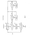
- FIG 4 shows a state machine used to re-adjust an initially calibrated set of coefficients derived from, e.g., the procedure described in FIG 2 .
- the re-adjustment may help mitigate the inaccuracies of factory calibration, as well as inaccuracies due to aging of the crystal and/or oscillator.
- the re-adjustment procedure begins at state FIELD0.
- the state FIELD0 calibrates the coefficient c0.
- the calibration of c0 may be done according to operations described later herein with reference to FIG 5 .
- State FIELD0 may transition to state FIELD1 when a predetermined set of conditions (labeled "Done" in FIG 4 ) are met.
- State FIELD1 may calibrate coefficient c1, as well as c0. In an embodiment, the calibration of c0 and c1 may be done according to operations described later herein with reference to FIG 6 .
- State FIELD 1 may transition to state FIELD2 when a predetermined set of conditions are met.
- State FIELD 1 may also transition back to state FIELD0 if an aging timer expires.
- the aging timer may track the amount of time elapsed since any coefficient has last been updated.
- the aging timer may be an electronic counter resident on a chip with the oscillator, or it may be a module that compares a time stamp stored during the last coefficient update with the current time stamp.
- the aging timer can be set to expire two years after a last calibration.
- state FIELD2 may calibrate coefficient c2, as well as coefficients c1 and/or c0. State FIELD2 may transition to state FIELD3 when a predetermined set of conditions are met. State FIELD2 may also transition back to FIELD0 if the aging timer expires.
- State FIELD3 may calibrate coefficient c3, as well as coefficients c2, c1, and/or c0. In an embodiment, the calibration of c3, c2, c1, c0 may be done according to operations described later herein with reference to FIG 7 . State FIELD3 may transition to state FIELD4 when a predetermined set of conditions are met. Alternatively, state FIELD3 may transition back to FIELD0.
- state FIELD4 may be a sleep state.
- the calibration mechanism may cease operation for a predetermined amount of time.
- the predetermined amount of time may be one year.
- state FIELD 1 may skip FIELD2 and transition directly to state FIELD3 upon the predetermined set of conditions being met.
- the current state (i.e., FIELD0, FIELD1, FIELD2, FIELD3, or FIELD4) of the state machine is stored in nonvolatile memory, such that the state is preserved upon power-up or power-down of a device utilizing the crystal oscillator.
- the crystal oscillator may be used in a wireless handset.
- FIG 5 shows an embodiment of operations performed during state FIELD0. Note the embodiment illustrated in FIG 5 is not meant to limit the scope of the disclosure to any particular set of operations in FIELD0. Rather, one of ordinary skill in the art will realize that any steps used to update an estimate of the coefficients may be performed during any of the states FIELD0, FIELD1, FIELD2, FIELD3, and FIELD4. Such embodiments are contemplated to be within the scope of the present disclosure.
- a counter n0 for counting iterations of a loop is initialized to zero.
- the state machine commences by waiting for a period of time FT_update0 seconds.
- the temperature T e.g., in degrees Celsius
- the temperature T is measured.
- T 0 is set to 30 degrees Celsius
- T 1 is set to 15 degrees Celsius.
- the actual measured frequency of the oscillator fm may be derived from an automatic frequency control circuit used in, for example, a receiver apparatus for code-division multiple access (CDMA).
- CDMA code-division multiple access
- n0 is compared to a variable maxIterations0. If n0 has reached a variable maxIterations0, then the state machine exits state FIELD0 and proceeds to the next state. If n0 has not reached maxIterations0, then the state returns to step 500.
- FIG 6 shows an embodiment of operations performed during state FIELD1. In state FIELD1, a counter n1 for counting the iterations is initially set to zero. At step 600, the state machine waits for a period of time FT_update1 seconds. At the end of FT_update1 seconds, the temperature T (e.g., in degrees Celsius) of the crystal is measured.
- T e.g., in degrees Celsius
- step 610 it is checked whether T falls within the range T 1 ⁇
- step 625 can be identical to the operations described with reference to step 520 in FIG 5 .
- an iteration index may also be provided for updating coefficient c0.
- T 2 is 30 degrees Celsius.
- the coefficient c1[n1] is updated.
- c1[n1] may be updated as follows. Given the current value of c0, candidate values of c1[n1] may be assessed to determine the best c1 candidate for the measured frequency and temperature, according to some optimality criteria.
- the optimality criteria may include the error between a measured temperature-frequency pair and the computed temperature-frequency characteristic, assuming the current value of c0 and a candidate value of c1.
- the search for the best c1 may be aided by assuming a linear relationship between c1 and c2/c3, e.g., as described with reference to FIGs 3A and 3B .
- c1 may be IIR filtered with a previous estimate of c1.
- the IIR weighting constant can be 256.
- n1 is compared to a variable maxIterations1. If n1 has reached maxIterations0, then the state machine exits state FIELD 1 and proceeds to the next state. If n1 has not reached maxIterations1, then the state returns to step 600.
- state FIELD2 may be implemented similarly to the states FIELD0 and FIELD1 previously described. In an alternative embodiment, FIELD2 need not be implemented if the coefficient c2 is predetermined to be close to zero. In this embodiment, state FIELD 1 may bypass FIELD2 and directly transition to FIELD3.
- FIG 7 shows an embodiment of the operations performed during state FIELD3.
- a counter n3 for counting the iterations is initially set to zero.
- the state machine waits for a period of time FT_update3 seconds.
- the temperature T e.g., in degrees Celsius
- the current estimate for c3 is updated at step 720.
- candidate values of c3 may be assessed to determine the best c3 for the measured frequency and temperature, according to some optimality criteria. Once a best c3 is determined, it may be IIR filtered with a previous estimate of c3.
- n3 is compared to a variable maxIterations3. If n3 has reached maxIterations0, then the state machine proceeds to the next state. If n3 has not reached maxIterations3, then the state returns to step 700.
- the state machine may transition to the next state upon detecting little or no change in the coefficient to be updated.
- the state machine may transition from FIELD0 to FIELD1 if
- delta has a suitably small value.
- the functions described may be implemented in hardware, software, firmware, or any combination thereof. If implemented in software, the functions may be stored on or transmitted over as one or more instructions or code on a computer-readable medium.
- Computer-readable media includes both computer storage media and communication media including any medium that facilitates transfer of a computer program from one place to another.
- a storage media may be any available media that can be accessed by a computer.
- such computer-readable media can comprise RAM, ROM, EEPROM, CD-ROM or other optical disk storage, magnetic disk storage or other magnetic storage devices, or any other medium that can be used to carry or store desired program code in the form of instructions or data structures and that can be accessed by a computer.
- any connection is properly termed a computer-readable medium.
- the software is transmitted from a website, server, or other remote source using a coaxial cable, fiber optic cable, twisted pair, digital subscriber line (DSL), or wireless technologies such as infrared, radio, and microwave
- the coaxial cable, fiber optic cable, twisted pair, DSL, or wireless technologies such as infrared, radio, and microwave are included in the definition of medium.
- .Disk and disc includes compact disc (CD), laser disc, optical disc, digital versatile disc (DVD), floppy disk and blu-ray disc where disks usually reproduce data magnetically, while discs reproduce data optically with lasers. Combinations of the above should also be included within the scope of computer-readable media.
Landscapes
- Oscillators With Electromechanical Resonators (AREA)
Priority Applications (4)
| Application Number | Priority Date | Filing Date | Title |
|---|---|---|---|
| JP2010545175A JP2011511575A (ja) | 2008-01-31 | 2009-01-29 | 水晶発振器周波数較正 |
| CN2009801070884A CN101965568A (zh) | 2008-01-31 | 2009-01-29 | 晶体振荡器频率校准 |
| KR1020107019300A KR20100105900A (ko) | 2008-01-31 | 2009-01-29 | 수정 발진기 주파수 교정 |
| PCT/US2009/032503 WO2009099903A1 (en) | 2008-01-31 | 2009-01-29 | Crystal oscillator frequency calibration |
Applications Claiming Priority (1)
| Application Number | Priority Date | Filing Date | Title |
|---|---|---|---|
| US12/023,796 US20090195322A1 (en) | 2008-01-31 | 2008-01-31 | Crystal oscillator frequency calibration |
Publications (1)
| Publication Number | Publication Date |
|---|---|
| EP2085900A1 true EP2085900A1 (en) | 2009-08-05 |
Family
ID=40635465
Family Applications (1)
| Application Number | Title | Priority Date | Filing Date |
|---|---|---|---|
| EP08005890A Withdrawn EP2085900A1 (en) | 2008-01-31 | 2008-03-27 | Crystal oscillator frequency calibration |
Country Status (7)
| Country | Link |
|---|---|
| US (1) | US20090195322A1 (https=) |
| EP (1) | EP2085900A1 (https=) |
| JP (1) | JP2011511575A (https=) |
| KR (1) | KR20100105900A (https=) |
| CN (1) | CN101965568A (https=) |
| TW (1) | TW201001210A (https=) |
| WO (1) | WO2009099903A1 (https=) |
Families Citing this family (17)
| Publication number | Priority date | Publication date | Assignee | Title |
|---|---|---|---|---|
| US8031024B1 (en) | 2008-02-28 | 2011-10-04 | Marvell International Ltd. | Temperature-corrected frequency control with crystal oscillators |
| US8731119B2 (en) | 2011-03-18 | 2014-05-20 | Marvell World Trade Ltd. | Apparatus and method for reducing receiver frequency errors |
| US9289422B2 (en) * | 2011-03-24 | 2016-03-22 | Marvell World Trade Ltd. | Initial acquisition using crystal oscillator |
| US20140004887A1 (en) | 2012-06-29 | 2014-01-02 | Qualcomm Incorporated | Crystal oscillator calibration |
| CN104716922B (zh) * | 2013-12-12 | 2019-01-25 | 深圳富泰宏精密工业有限公司 | 电子装置 |
| GB2521461B (en) * | 2013-12-20 | 2020-08-19 | St Microelectronics Res & Dev Ltd | Frequency error |
| US9872335B2 (en) | 2015-03-06 | 2018-01-16 | Marvell International Ltd. | Iterative receiver wake-up for long DRX periods |
| US10333525B1 (en) | 2015-12-07 | 2019-06-25 | Marvell International Ltd. | Digitally-based temperature compensation for a crystal oscillator |
| CN107465393B (zh) * | 2017-07-05 | 2020-12-01 | 广州昂宝电子有限公司 | 用于实时时钟系统的频率补偿的系统和方法 |
| US10823623B2 (en) | 2018-04-26 | 2020-11-03 | Samsung Electronics Co., Ltd | System and method for modeling and correcting frequency of quartz crystal oscillator |
| CN112292814B (zh) * | 2018-07-05 | 2024-11-15 | 华为技术有限公司 | 晶体判定方法、装置及存储介质 |
| CN110212863B (zh) * | 2019-05-31 | 2024-02-13 | Oppo广东移动通信有限公司 | 校准晶体振荡器的方法、装置、电子设备及存储介质 |
| CN110336535A (zh) * | 2019-06-12 | 2019-10-15 | Oppo广东移动通信有限公司 | 一种晶体振荡器校准方法、装置、终端设备及存储介质 |
| CN112083226A (zh) * | 2019-06-13 | 2020-12-15 | Oppo广东移动通信有限公司 | 电子设备的频率校准方法、装置、介质及电子设备 |
| CN110262210B (zh) * | 2019-06-28 | 2021-03-26 | 北斗天汇(北京)科技有限公司 | 基于计数器的晶振守时方法 |
| CN111162751A (zh) * | 2020-02-17 | 2020-05-15 | 广东惠伦晶体科技股份有限公司 | 一种改善动态热漂移的晶振 |
| CN111884589B (zh) * | 2020-08-26 | 2021-11-05 | 硅谷数模(苏州)半导体有限公司 | 频率源的温度补偿参数确定方法和装置 |
Family Cites Families (33)
| Publication number | Priority date | Publication date | Assignee | Title |
|---|---|---|---|---|
| US2731564A (en) * | 1951-11-05 | 1956-01-17 | Edelstein Harold | Barium titanate temperature control |
| JPS5574222A (en) * | 1978-11-30 | 1980-06-04 | Nec Corp | Temperature compensation circuit for crystal oscillator |
| US4453834A (en) * | 1981-07-03 | 1984-06-12 | Citizen Watch Company Limited | Electronic timepiece with temperature compensation |
| JPH01313728A (ja) * | 1988-06-13 | 1989-12-19 | Seiko Electronic Components Ltd | 水晶式真空計 |
| DE4302542A1 (de) * | 1993-01-29 | 1994-08-04 | Siemens Ag | Oszillatorschaltung mit einem die schwingquarzindividuellen Kenninformationen speichernden Speicher |
| JPH06291550A (ja) * | 1993-04-01 | 1994-10-18 | Seiko Epson Corp | ディジタル型温度補償圧電発振器及び通信機 |
| JP3211134B2 (ja) * | 1994-10-31 | 2001-09-25 | 京セラ株式会社 | 水晶振動子の発振周波数算出方法 |
| JPH0918234A (ja) * | 1995-04-27 | 1997-01-17 | Seiko Epson Corp | 温度補償圧電発振器 |
| US5757244A (en) * | 1996-02-23 | 1998-05-26 | Kyocera Corporation | Digital control type oscillation circuit of portable telephone, crystal resonator oscillation frequency calculating method, and outputfrequency correcting method |
| US6584380B1 (en) * | 1997-06-02 | 2003-06-24 | Asahi Kasei Microsystems Co., Ltd. | Approximate third-order function generator, temperature compensation quartz oscillation circuit made by using the same, and temperature compensation method |
| JPH11220327A (ja) * | 1997-10-31 | 1999-08-10 | Dynamics Corp Of America | 発振器の温度補償回路 |
| US6775632B1 (en) * | 1999-12-14 | 2004-08-10 | The Goodyear Tire & Rubber Company | Calibration of a transponders for a tire pressure monitoring system |
| CA2341316A1 (en) * | 2000-03-17 | 2001-09-17 | Samir Kuliev | Digital indirectly compensated crystal oscillators |
| JP2001267847A (ja) * | 2000-03-17 | 2001-09-28 | Asahi Kasei Microsystems Kk | 温度補償型水晶発振器及び水晶発振器の温度補償方法 |
| US6420938B1 (en) * | 2000-08-30 | 2002-07-16 | Lawrence Hoff | Software controlled crystal oscillator |
| JP4454126B2 (ja) * | 2000-09-05 | 2010-04-21 | シチズンホールディングス株式会社 | 温度補償発振器の調整方法 |
| US6472943B1 (en) * | 2000-12-21 | 2002-10-29 | Telefonaktie Bolaget L.M. Ericsson | Oscillating circuit and method for calibrating same |
| JP2002299957A (ja) * | 2001-03-29 | 2002-10-11 | Kyocera Corp | 水晶発振器の温度特性補正方法 |
| US6661302B1 (en) * | 2001-04-30 | 2003-12-09 | Cts Corporation | Compensation algorithm for crystal curve fitting |
| US6636121B2 (en) * | 2001-05-31 | 2003-10-21 | Intel Corporation | Method for estimating crystal coefficient values for a signal generator |
| US6630872B1 (en) * | 2001-07-20 | 2003-10-07 | Cmc Electronics, Inc. | Digital indirectly compensated crystal oscillator |
| JP4449274B2 (ja) * | 2002-05-01 | 2010-04-14 | セイコーエプソン株式会社 | 圧電発振器、およびその圧電発振器を用いた受信装置 |
| AU2003261760A1 (en) * | 2002-08-28 | 2004-04-30 | Asahi Kasei Microsystems Co., Ltd. | DEVICE FOR GENERATING FUNCTION OF APPROXIMATE n-TH DEGREE AND TEMPERATURE COMPENSATION QUARTZ OSCILLATION CIRCUIT |
| JP4513742B2 (ja) * | 2003-03-17 | 2010-07-28 | セイコーエプソン株式会社 | 発振器の特性自動補償装置、特性自動補償方法、特性自動補償プログラム、及び測位信号受信機 |
| US6995622B2 (en) * | 2004-01-09 | 2006-02-07 | Robert Bosh Gmbh | Frequency and/or phase compensated microelectromechanical oscillator |
| US7015762B1 (en) * | 2004-08-19 | 2006-03-21 | Nortel Networks Limited | Reference timing signal apparatus and method |
| US7310024B2 (en) * | 2005-02-28 | 2007-12-18 | Milliren Bryan T | High stability double oven crystal oscillator |
| US20090063070A1 (en) * | 2005-06-24 | 2009-03-05 | Carl Peter Renneberg | Circuit and Method for Fitting the Output of a Sensor to a Predetermined Linear Relationship |
| US20070057737A1 (en) * | 2005-09-14 | 2007-03-15 | Freescale Semiconductor, Inc. | Compensation for modulation distortion |
| US7627060B2 (en) * | 2006-03-21 | 2009-12-01 | Intel Corporation | Receiver and method having envelope compensation signal |
| US7649426B2 (en) * | 2006-09-12 | 2010-01-19 | Cts Corporation | Apparatus and method for temperature compensation of crystal oscillators |
| US7466209B2 (en) * | 2007-01-05 | 2008-12-16 | Sirf Technology, Inc. | System and method for providing temperature correction in a crystal oscillator |
| JP4453719B2 (ja) * | 2007-05-29 | 2010-04-21 | ソニー株式会社 | 温度補償型水晶発振器 |
-
2008
- 2008-01-31 US US12/023,796 patent/US20090195322A1/en not_active Abandoned
- 2008-03-27 EP EP08005890A patent/EP2085900A1/en not_active Withdrawn
-
2009
- 2009-01-29 JP JP2010545175A patent/JP2011511575A/ja active Pending
- 2009-01-29 KR KR1020107019300A patent/KR20100105900A/ko not_active Abandoned
- 2009-01-29 CN CN2009801070884A patent/CN101965568A/zh active Pending
- 2009-01-29 WO PCT/US2009/032503 patent/WO2009099903A1/en not_active Ceased
- 2009-02-02 TW TW098103265A patent/TW201001210A/zh unknown
Non-Patent Citations (3)
| Title |
|---|
| ARTHUR BALLATO: "Frequency-Temperature-Load Capacitance Behavior of Resonators for TCXO", APPLICATION," IEEE TRANS. SONICS AND ULTRASONICS, vol. SU-25, no. 4, July 1978 (1978-07-01) |
| BALLATO A: "Frequency-temperature-load capacitance behavior of resonators for TCXO application", IEEE TRANSACTIONS ON SONICS AND ULTRASONICS USA, vol. SU-25, no. 4, July 1978 (1978-07-01), pages 185 - 191, XP002528763, ISSN: 0018-9537 * |
| PERETTO L ET AL: "A System for the Measurement of the Temperature Dependence Performances of Quartz Oscillators: a Study of the Analytical Model of the Failure Rate", INSTRUMENTATION AND MEASUREMENT TECHNOLOGY CONFERENCE PROCEEDINGS, 200 7 IEEE, IEEE, PI, 1 May 2007 (2007-05-01), pages 1 - 6, XP031182227, ISBN: 978-1-4244-0588-6 * |
Also Published As
| Publication number | Publication date |
|---|---|
| CN101965568A (zh) | 2011-02-02 |
| KR20100105900A (ko) | 2010-09-30 |
| US20090195322A1 (en) | 2009-08-06 |
| TW201001210A (en) | 2010-01-01 |
| JP2011511575A (ja) | 2011-04-07 |
| WO2009099903A1 (en) | 2009-08-13 |
Similar Documents
| Publication | Publication Date | Title |
|---|---|---|
| EP2085900A1 (en) | Crystal oscillator frequency calibration | |
| JP2011511575A5 (https=) | ||
| US9024698B2 (en) | Temperature compensation method and crystal oscillator | |
| US20020158693A1 (en) | Oscillating circuit and method for calibrating same | |
| US10763781B2 (en) | System and method of crystal oscillator temperature compensation for operation in extended temperature range | |
| US7466209B2 (en) | System and method for providing temperature correction in a crystal oscillator | |
| EP2482458B1 (en) | Oscillation device | |
| US6545550B1 (en) | Residual frequency effects compensation | |
| US6636121B2 (en) | Method for estimating crystal coefficient values for a signal generator | |
| WO1995011456A1 (en) | Frequency counter and frequency counting method | |
| US20120042192A1 (en) | Frequency Reference Correction for Temperature-Frequency Hysteresis Error | |
| WO2016206384A1 (zh) | 晶体振荡器电路、晶体振荡器电路的调谐方法及存储介质 | |
| US9484855B2 (en) | System and methods for correcting clock synchronization errors | |
| JP2009177771A (ja) | 発振回路装置の経年劣化補償方法及び制御モジュール | |
| EP1696569B1 (en) | A method and apparatus for generating an input signal for a parameter sensitive circuit | |
| Stofanik et al. | Multi-mode crystal oscillator for simultaneous excitation of three thickness-shear modes in stress compensated resonator | |
| CN117811573A (zh) | 频偏补偿方法、时钟信号的生成方法、电子设备和介质 | |
| Štofanik et al. | Investigation of drive level dependencies of higher overtones in SC quartz resonators | |
| Shioda et al. | High precision TCXO for rapid environmental temperature change | |
| JP6854646B2 (ja) | 電子発振器において機械共振器を動作させるためのシステム及び方法 | |
| WO2002051012A1 (en) | Oscillating circuit and method for calibrating same | |
| Stofanik et al. | Investigation of self-temperature-sensing of SC-cut with simultaneous excitation of two higher overtones in dual-mode crystal oscillator | |
| Weaver et al. | An insitu technique for the resolution of aging contributions between quartz resonators and oscillator circuits | |
| Deno et al. | A low cost high stability microcontroller compensated crystal oscillator | |
| CA1078932A (en) | Quartz crystal resonator |
Legal Events
| Date | Code | Title | Description |
|---|---|---|---|
| PUAI | Public reference made under article 153(3) epc to a published international application that has entered the european phase |
Free format text: ORIGINAL CODE: 0009012 |
|
| AK | Designated contracting states |
Kind code of ref document: A1 Designated state(s): AT BE BG CH CY CZ DE DK EE ES FI FR GB GR HR HU IE IS IT LI LT LU LV MC MT NL NO PL PT RO SE SI SK TR |
|
| AX | Request for extension of the european patent |
Extension state: AL BA MK RS |
|
| 17P | Request for examination filed |
Effective date: 20091012 |
|
| 17Q | First examination report despatched |
Effective date: 20091106 |
|
| AKX | Designation fees paid |
Designated state(s): AT BE BG CH CY CZ DE DK EE ES FI FR GB GR HR HU IE IS IT LI LT LU LV MC MT NL NO PL PT RO SE SI SK TR |
|
| STAA | Information on the status of an ep patent application or granted ep patent |
Free format text: STATUS: THE APPLICATION IS DEEMED TO BE WITHDRAWN |
|
| 18D | Application deemed to be withdrawn |
Effective date: 20141001 |