EP2085239A1 - Kennzeichnungsvorrichtung und Zigarettenstrangmaschine - Google Patents
Kennzeichnungsvorrichtung und Zigarettenstrangmaschine Download PDFInfo
- Publication number
- EP2085239A1 EP2085239A1 EP09005260A EP09005260A EP2085239A1 EP 2085239 A1 EP2085239 A1 EP 2085239A1 EP 09005260 A EP09005260 A EP 09005260A EP 09005260 A EP09005260 A EP 09005260A EP 2085239 A1 EP2085239 A1 EP 2085239A1
- Authority
- EP
- European Patent Office
- Prior art keywords
- printing
- cigarette paper
- motif
- movement
- motifs
- Prior art date
- Legal status (The legal status is an assumption and is not a legal conclusion. Google has not performed a legal analysis and makes no representation as to the accuracy of the status listed.)
- Withdrawn
Links
- 235000019504 cigarettes Nutrition 0.000 title claims abstract description 86
- 238000007639 printing Methods 0.000 claims abstract description 178
- 241000208125 Nicotiana Species 0.000 description 18
- 235000002637 Nicotiana tabacum Nutrition 0.000 description 18
- 238000000034 method Methods 0.000 description 12
- 239000000976 ink Substances 0.000 description 11
- XXUZFRDUEGQHOV-UHFFFAOYSA-J strontium ranelate Chemical compound [Sr+2].[Sr+2].[O-]C(=O)CN(CC([O-])=O)C=1SC(C([O-])=O)=C(CC([O-])=O)C=1C#N XXUZFRDUEGQHOV-UHFFFAOYSA-J 0.000 description 5
- 239000000835 fiber Substances 0.000 description 4
- 230000008859 change Effects 0.000 description 3
- 238000002372 labelling Methods 0.000 description 3
- 238000004519 manufacturing process Methods 0.000 description 3
- 230000008569 process Effects 0.000 description 3
- 230000001105 regulatory effect Effects 0.000 description 3
- 230000008901 benefit Effects 0.000 description 2
- 239000003086 colorant Substances 0.000 description 2
- 230000001419 dependent effect Effects 0.000 description 2
- 239000004744 fabric Substances 0.000 description 2
- 238000007641 inkjet printing Methods 0.000 description 2
- 238000010020 roller printing Methods 0.000 description 2
- 238000003892 spreading Methods 0.000 description 2
- 230000007480 spreading Effects 0.000 description 2
- 238000003860 storage Methods 0.000 description 2
- 238000005520 cutting process Methods 0.000 description 1
- 238000007646 gravure printing Methods 0.000 description 1
- 238000007645 offset printing Methods 0.000 description 1
- 239000002245 particle Substances 0.000 description 1
- 239000013589 supplement Substances 0.000 description 1
- 230000001360 synchronised effect Effects 0.000 description 1
- 230000032258 transport Effects 0.000 description 1
- 230000037303 wrinkles Effects 0.000 description 1
Images




Classifications
-
- B—PERFORMING OPERATIONS; TRANSPORTING
- B41—PRINTING; LINING MACHINES; TYPEWRITERS; STAMPS
- B41J—TYPEWRITERS; SELECTIVE PRINTING MECHANISMS, i.e. MECHANISMS PRINTING OTHERWISE THAN FROM A FORME; CORRECTION OF TYPOGRAPHICAL ERRORS
- B41J11/00—Devices or arrangements of selective printing mechanisms, e.g. ink-jet printers or thermal printers, for supporting or handling copy material in sheet or web form
- B41J11/36—Blanking or long feeds; Feeding to a particular line, e.g. by rotation of platen or feed roller
- B41J11/42—Controlling printing material conveyance for accurate alignment of the printing material with the printhead; Print registering
-
- A—HUMAN NECESSITIES
- A24—TOBACCO; CIGARS; CIGARETTES; SIMULATED SMOKING DEVICES; SMOKERS' REQUISITES
- A24C—MACHINES FOR MAKING CIGARS OR CIGARETTES
- A24C5/00—Making cigarettes; Making tipping materials for, or attaching filters or mouthpieces to, cigars or cigarettes
- A24C5/005—Treatment of cigarette paper
-
- A—HUMAN NECESSITIES
- A24—TOBACCO; CIGARS; CIGARETTES; SIMULATED SMOKING DEVICES; SMOKERS' REQUISITES
- A24C—MACHINES FOR MAKING CIGARS OR CIGARETTES
- A24C5/00—Making cigarettes; Making tipping materials for, or attaching filters or mouthpieces to, cigars or cigarettes
- A24C5/60—Final treatment of cigarettes, e.g. marking, printing, branding, decorating
- A24C5/601—Marking, printing or decorating cigarettes
-
- B—PERFORMING OPERATIONS; TRANSPORTING
- B41—PRINTING; LINING MACHINES; TYPEWRITERS; STAMPS
- B41J—TYPEWRITERS; SELECTIVE PRINTING MECHANISMS, i.e. MECHANISMS PRINTING OTHERWISE THAN FROM A FORME; CORRECTION OF TYPOGRAPHICAL ERRORS
- B41J11/00—Devices or arrangements of selective printing mechanisms, e.g. ink-jet printers or thermal printers, for supporting or handling copy material in sheet or web form
- B41J11/0085—Using suction for maintaining printing material flat
Definitions
- the invention relates to an identification device for identifying a moving object, a cigarette rod machine and a method for identifying a moving object.
- paper which is, for example, on a roll, unrolled, passed between two pressure rollers, printed and, for example, rolled up again or assembled for further processing.
- the paper is pressed by a counter-pressure roller to a pressure roller and the motif to be imaged is transferred from the pressure roller to the paper.
- high, low and gravure printing techniques can be used to transfer the motif, with very high printing speeds being achieved.
- the motif to be printed will be changed in that, for example, the pressure roller or the roller system is changed.
- the pressure roller or the roller system is changed.
- the DE 101 30 225 A1 describes, for example, a printing unit for printing on cigarette paper as part of a cigarette rod machine of the type PROTOS, as known in the cigarette industry.
- FIG. 6 is a cigarette rod machine of the type PROTOS shown schematically.
- a pre-distributor 102 is charged in portions with tobacco fibers.
- a removal roller 103 of the pre-distributor 102 controlled supplements a reservoir 104 with tobacco, from which a steep conveyor 105 takes tobacco and fed a stowage 106 controlled.
- a pin roller 107 removes a uniform stream of tobacco which is knocked out of the pins of the pin roller 107 by a knock-out roller 108 and thrown onto a spreading cloth 109 rotating at a constant speed.
- a tobacco fleece formed on the spreading cloth 109 is thrown into a sighting device 111 consisting essentially of an air curtain passing through larger or heavier tobacco parts, while all other tobacco particles are transferred from the air into a funnel 114 formed by a pin roller 112 and a wall 113 be steered.
- tobacco fibers are thrown in a tobacco channel 116 against a strand conveyor 117, where the tobacco held by means sucked into a vacuum chamber 118 air and a tobacco fiber strand is alsauert.
- An equalizer 119 removes excess tobacco from the tobacco fiber strand, which is then placed on a synchronized cigarette paper strip 121.
- the zig-bear paper strip 121 is pulled off a bobbin 122, passed through a printing unit 123 and placed on a driven format belt 124.
- the format belt 124 transports the tobacco rod and the cigarette paper strip 121 through a format 126, in which the cigarette paper strip 121 is folded around the tobacco rod, so that still protrudes an edge which is glued in a known manner by a Glimapparat, not shown. Then the seam is closed and dried by a Tandemnahtplätte 127.
- a thus formed cigarette rod 128 passes through a strand density meter 129, which controls the leveler 119, and is cut by a knife apparatus 131 into double-length cigarettes 132.
- the double-length cigarettes 132 are transferred from a transfer arm 134, which has a controlled arm 133, to a transfer drum 136 of a filter attachment machine 137, onto the cutting drum 138 of which they are divided into single cigarettes with a circular blade.
- Conveyor belts 139, 141 promote excess tobacco in a container 142 arranged below the storage container 104, from which the recirculated tobacco is removed again from the steep conveyor 105.
- the printing unit 123 can be completely changed, whereby a complicated changing individual pressure rollers is avoided.
- a plurality of pressure rollers or roller-mountable printing forms or complete printing roller printing units are provided for changing, so that a variety of different motifs can be printed. If the motif is to be changed, the rollers or the printing plates or the roller printing units can be exchanged. However, the printing process must be interrupted, resulting in dead times of the printing device.
- a moving object can be characterized at high speed.
- the motif can be changed or changed substantially without changing the marking device.
- a further advantage of the invention is that the motif can be changed quickly and easily, especially while the marking device is in operation, whereby any number of different motifs can be printed inexpensively. In particular, it is not necessary that structural changes be made to the marking device.
- an identification device for identifying an object moved in a direction of movement, comprising at least two printing devices adapted to respectively generate a predetermined image and each adapted to sequentially print the article with the motifs in a non-contact manner in such a way that an overall motif is formed from the individual motifs.
- an arbitrary motif may be produced by suitable control or regulation of the at least two pressure devices.
- the moving object is operated without contact, whereby wear and tear, as they occur for example in rotating pressure rollers, especially at high speeds of the pressure rollers, do not occur.
- each printing device prints in a printing direction, the printing direction being at a different angle from 0 ° and 180 °, preferably substantially perpendicular to the direction of movement of the moving article.
- the angle between the printing direction and the direction of movement is measured in plan view.
- the printing direction and the direction of movement essentially span one plane, wherein this plane is substantially parallel to a surface of the article to be printed.
- substantially any motif may be formed on the article.
- the moving object at a predetermined or predeterminable printing resolution r, can be printed at the predetermined or predeterminable printing speed v by selecting the number n of the printing devices used at a substantially constant printing frequency f .
- the resolution of the printed overall motif r can be increased by increasing the number n of printing devices.
- the preferred identification device of the present invention is very flexible in terms of the overall printed motif, the resolution of the overall printed subject, and / or the speed at which the printed article passes the printing device.
- the number of required printing devices n may be determined using the above relationship of r, f and v .
- the moving object is preferably cigarette paper, more preferably cigarette paper from a roll.
- the cigarette paper is in the form of a substantially long web, formed substantially unassembled.
- cigarette paper can be drawn at a speed of about 100 ⁇ m min until about 1200 ⁇ m min . preferably at a rate of about 500 ⁇ m min until about 900 ⁇ m min be printed.
- a resolution in the direction of movement preferably about 1 point per mm (about 25 dpi) to about 24 points per mm (about 600 dpi), more preferably from about 6 points per mm (about 150 dpi) to about 18 points per mm ( about 455 dpi) can be achieved.
- the predetermined or predeterminable motifs of two different printing devices are identical motifs.
- the preferred identification device of the present invention can produce an overall motif composed of a plurality of identical patterns, such as a plurality of identical geometric shapes.
- the predetermined or predeterminable motifs of two different printing devices are different motifs.
- the overall motif can be made, the overall motif consisting of a variety of different motifs.
- an overall motif can be made from a variety of combined geometric shapes. It is also conceivable, for example, for a brand name to be printed, with each printing unit printing, for example, a letter or a part of a letter of the brand name.
- each printer may print lines, circles, and / or other graphic patterns. It is also possible for the printing devices to use numbers and / or symbols, such as numbers. print mathematical characters.
- the marking device comprises at least one receiving device, which is arranged fixed or movable on the marking device.
- the receiving device can therefore be attached to the marking device, for example, such that the receiving device moves relative to the moving body, whereby the relative speed between the receiving device and the moving object can be changed.
- the receiving device movable, preferably rotating, on the marking device.
- the receiving device may comprise a rotatably mounted wheel or a rotatably mounted cylindrical disk on or in which the printing devices are mounted. By rotation of the cylinder disc, at least one of the at least two pressure devices is preferably alternately brought into a position in which the moving object can be printed.
- the printing devices are each housed in a separate receiving device.
- each printing device can be individually moved relative to the moving article.
- all printing devices are housed in a common receiving device.
- the at least two printing devices are arranged substantially in the direction of movement, particularly preferably in a row in the direction of movement.
- each printing device prints in a printing direction, wherein the printing direction is at an angle different from 0 ° and 180 °, preferably substantially perpendicular to the moving direction of the moving object.
- v is a relative velocity between the pressure devices and the moving one
- f is a printing frequency of a printing device and n is the number of printing devices.
- the relative velocity v is between about 100 ⁇ m min until about 1200 ⁇ m min . more preferably between about 500 ⁇ m min until about 900 ⁇ m min ,
- the moving object is cigarette paper and the cigarette paper is preferably designed as a substantially long web, substantially unassembled, prior to marking.
- FIG. 1 shows a front view of a marking system 10 according to a preferred embodiment of the invention.
- cigarette paper 14 is guided via deflection rollers 16 to a printing table 18.
- the cigarette paper 14 is guided on a surface 20 of the printing table 18 to a preferred embodiment of an identification device 22 of the present invention.
- the cigarette paper 14 is guided, for example, further in the direction of movement BR substantially along or on the surface 20 of the printing table 18 between the surface 20 of the printing table 18 and at least one receiving device 24 of the marking device 22.
- the cigarette paper 14 by at least two printing devices (not shown), which are each arranged on the receiving means 24, printed.
- such printing devices may be conventional ink jet print cartridges as used in commercial ink jet printers.
- the cigarette paper 14 is printed without contact, that is without contact between the marking device 22 and the printing area of the marking device 24 and the cigarette paper 14.
- the printing area of the marking device 24 may be an ink outlet area of the ink jet print cartridge.
- the printed cigarette paper 14 is preferably assembled with predetermined dimensions. But it is also possible that the cigarette paper 14, after it has been printed, fed via a plurality of other pulleys 26 a holder 28, and is rolled up there.
- FIG. 2 shows a detailed view of a preferred embodiment of the identification device 22 of the present invention.
- the preferred marking device 22 comprises, for example, two receiving devices 24, which are each designed to substantially receive a printing device (not shown) or to attach it in a preferably detachable manner, preferably in a detachable manner.
- the two receiving devices 24, for example, rigidly connected to each other and rigidly attached to a surface 30 of the marking system 10. It is also possible that the two receiving devices 24 are spaced from each other. Furthermore, it is possible that the two receiving devices 24 are movably connected to the marking device 22 and the surface 30 of the marking system 10. For example, the receiving devices 24 may be attached to a rotating cylinder disk or be an integral part of this cylinder disk.
- the cigarette paper 14 moves substantially along the surface 20 of the printing table 18 in the direction of movement BR. In this case, the cigarette paper 14 moves between the marking device 22 and the surface 20 of the printing table 18, wherein it does not come into contact with the printing devices of the marking device 22 substantially.
- the surface 20 of the printing table 18 has a plurality of openings 31.
- the openings 31 are preferably arranged in areas of the surface 20 of the printing table 18, on which the cigarette paper 14 runs along.
- the cigarette paper 14 can be substantially fixed in a printing direction DR by means of a controllable pressure difference with respect to the ambient pressure.
- the printing direction DR is a direction substantially parallel to the surface 20 of the printing table 18 and substantially perpendicular to the direction of movement BR.
- a negative pressure is generated at the openings 31 compared to the ambient pressure and by the negative pressure, the cigarette paper 14 substantially to the Surface 20 of the printing table 18 pulled out or sucked.
- the cigarette paper 14 can be moved substantially in the direction of movement BR, wherein the cigarette paper 14 is substantially fixed with respect to the printing direction DR. Characterized in that the cigarette paper 14 is pulled or sucked substantially to the surface 20 toward the cigarette paper 14 moves at least partially substantially plane-parallel to the surface 20 of the printing table 18, ie the cigarette paper casts at least partially no wrinkles, but is at least partially in essential plan. Specifically, the cigarette paper 14 is substantially planar in an area where it is printed by the tag device 22.
- the receiving devices 24 furthermore each have connections 32 with which the printing devices (not shown) are provided with a control or regulating device, for example a computer or a so-called embedded system or embedded controller 33 (shown in FIG. 1 ) can be connected for data exchange. Furthermore, the pressure devices can be supplied with power via the connections 32.
- a control or regulating device for example a computer or a so-called embedded system or embedded controller 33 (shown in FIG. 1 ) can be connected for data exchange.
- the pressure devices can be supplied with power via the connections 32.
- each receiving device on one side 34 which is opposite to the cigarette paper 14, an opening 35.
- the side 34 is substantially parallel to the surface 20 of the printing table 18.
- the receiving device 24 preferably has two sides 36 which are mutually preferably parallel and substantially perpendicular to the surface 20 of the printing table 18 and perpendicular to the direction of movement BR.
- Each receiving device 24 may also have a preferably pivotable locking device 38. In order to lock the locking device 38, for example, it is pivotable towards the surface 20, preferably substantially parallel to the surface 20 of the printing table 18. To unlock the locking device 38, for example, it is pivotable away from the surface 20 of the printing table 18, preferably substantially parallel to the surface 30 of the marking device 22.
- the receiving device 24 has a back 40, which preferably substantially parallel to the surface 30 of the marking system 10 and preferably in the is substantially perpendicular to the surface 20 of the printing table 18.
- the side 34, the sides 36, the locking device 38 and the back 40 substantially surround a cavity 41, in which the printing device is introduced.
- the dimensions of the cavity 41 are designed such that the pressure device fits substantially exactly in the cavity 41, while it is not necessary that the cavity 41 has a substantially cuboid shape. Rather, the cavity 41 is designed so that it is substantially adapted to the shape of the printing device.
- a projection (not shown) of the printing device engages in the opening 35 and movement of the printing device, in particular a movement of the printing device from the cavity 41, is substantially prevented by the locking device 38.
- the locking means 38 in the closed state is substantially parallel to the surface 20 of the printing table 18 and in the open state substantially parallel to the surface 30.
- the locking device 38 is designed so that the printing device is easily or easily releasably fixed in the cavity 41. In particular, a movement of the printing device is substantially prevented by the locking device 38. This is preferably achieved in that by the locking device 38, a contact pressure is exerted on the printing device, in particular the printing device is pressed into the cavity.
- the locking device 38 has the property that the printing device is releasably fixed in the cavity.
- the locking device 38 can preferably be easily locked and unlocked by a pivotable mounting of the locking device 38 and consequently the pressure device can be easily fixed or released in the cavity 41 and removed from the cavity 41.
- the printing device is fixed in the opening 35 and by the locking device 38 in the cavity 41 of the receiving device 24 substantially by inserting the projection (not shown).
- the printing device can be easily renewed or replaced.
- the printing device is a conventional ink cartridge
- this cartridge may be replaced, if the ink supply is exhausted or if you want to print in a different color.
- the receiving device 24 preferably has a connection (not shown), which can come into contact with control or regulating connections of the printing device.
- a connection (not shown), which can come into contact with control or regulating connections of the printing device.
- an electrical connection between the printing device and the control or regulating device, for example of the computer 33 can be made via the terminals 32.
- the computer or the embedded system or the embedded controller 33 preferably controls or regulates the printing performance of each printing device individually.
- the cigarette paper 14 is passed substantially between the receiving device 24 and the surface 20 of the printing table 18, wherein the cigarette paper 14 passes through the opening 35 of the receiving device 24 and is printed without contact by the printing device (not shown).
- FIG. 3a shows a plan view of the preferred labeling device 22.
- the two receptacles 24 are preferably offset in the printing direction DR.
- the leading edges 42 of the side 34 are not flush in the direction of movement BR, but are offset in the printing direction DR.
- the pressure ranges of the individual printing devices are also offset in printing direction DR.
- the effective width in printing direction DR, which can be printed by the printing devices, is thereby increased.
- FIG. 3b shows a further preferred embodiment of the present invention.
- the receiving means 24 are arranged such that the leading edges 42 of the side 34 in the direction of movement BR are substantially flush.
- the printing devices print on substantially the same areas on the cigarette paper 14. Otherwise corresponds to in FIG. 3b embodiment shown substantially the embodiment as shown in FIG. 3a is shown and described.
- the receiving means 24 are all offset in the printing direction DR or all receiving devices 24 are arranged substantially flush in the direction of movement BR. Rather, it is also possible that a first number of receiving means 24 are arranged offset in the printing direction DR and individual receiving means 24 of the remaining receiving means 24 are arranged to receptacles 24 of the first number in the direction of movement BR substantially flush.
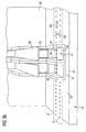
- FIG. 4 shows a side view of the identification device 22.
- the edges 42 of the page 34 are not flush in the direction of movement BR, but arranged offset in the printing direction DR.
- the back 40 it is not necessary that the back 40 be directly adjacent to the surface 30, but may be spaced therefrom.
- a guide device 43 may be attached, which is designed, for example, to stabilize the cigarette paper 14 or to guide it precisely past the printing device.
- the cigarette paper between the guide device 43 and the receiving device 24 are performed.
- the cigarette paper 14 is guided between the surface 20 of the printing table 18 and the guide device 43.
- the guide device 43 has an opening (not shown), which corresponds to the opening 35 substantially.
- the cigarette paper 14 is printed contactless substantially through these two openings.
- the guide device 43 can also be designed to fix the receiving device 24 or to fix it apart from the printing table 18 or the surface 30 or to fix it at a distance.
- the printing process in a preferred embodiment of the present identification device 22 is illustrated.
- the tagging device 22 comprises a number of six printing devices.
- the conventional ink jet printing cartridge injects ink onto the cigarette paper by means of nozzles
- substantially dots can be printed by the conventional ink jet printing cartridge, which are preferably arranged substantially parallel to the printing direction DR due to the arrangement of the nozzles. Consequently, the printed motifs are essentially composed of dots. Due to two mutually offset rows of nozzles per HP inkjet print cartridge and the possibility of freely programmable print triggering of each individual inkjet print cartridge used in the preferred embodiment of the present invention, the individual points merge more or less depending on the parameterization. Thus, although the motives consist essentially of individual points, it is preferably not possible to perceive the individual points separately because the points are too close to each other and / or run into each other.
- the first motif 44 is a series of six points, which are preferably arranged substantially perpendicular to the direction of movement BR of the cigarette paper 14.
- the six points are preferably arranged substantially parallel to the printing direction DR.
- the location of the first subject 44 in the direction of movement BR moves away from the first printing device toward the second printing device.
- FIG. 5b shows a second motif 46, which at a second time t2, ie, for example 14,11 ⁇ s after the time t1, was printed by the first printing device on the cigarette paper 14.
- the second motif 46 represents a single point.
- FIG. 5c is the cigarette paper 14 at time t3, ie, for example 28.33 ⁇ after t1 shown.
- the cigarette paper 14 has moved in the direction of movement BR, so that the location of the first motif 44 is located substantially in the direction of movement BR behind the second printing device.
- the second printing device prints a third motif 48 in the direction of movement BR next to the first motif 44 on the cigarette paper 14.
- the third motif 48 is represented by a hatched in the direction of BR BR to distinguish the third motif 48, for example, from the second motif 46.
- the third motif 48 (and all further motifs) will also consist of individual points, analogous to the first motif 44 or the second motif 46.
- all motifs are essentially composed of dots, as exemplified in motifs 44 and 46.
- a fourth motif 50 is shown, which at a time t4, ie, for example, 42.33 ⁇ s after t1, is printed by the second printing device substantially at a position in the direction of movement BR behind the second motif 46 on the cigarette paper.
- t4 ie, for example, 42.33 ⁇ s after t1
- the cigarette paper 14 continues to move in the direction of movement BR, and as soon as the second motif 46 is substantially behind the second printing device in the direction of movement BR, the second printing device prints the fourth motif 50.
- FIG. 5i shows the overall motif 52, in this example the letter E, which is formed from individual motifs which are produced or printed by a plurality of printing devices.
- the individual motifs are printed side by side, for example. Consequently, the overall motif 52 is created by sequentially printing a plurality of individual motifs.
- the individual motifs are not restricted to one line in printing direction DR.
- the first motif 44 also includes the third motif 48, if the desired resolution r is still reached at the speed v at which the cigarette paper 14 is moved and the printing frequency f of the inkjet print cartridge, taking into account the above relationship can.
- the printing devices also print on regions several times, ie that, for example, a printing device repeatedly prints a region of the cigarette paper 14.
- different printing devices it is also possible for different printing devices to print or reprint a region of the cigarette paper 14.
- a region of the cigarette paper 14 may be printed by a plurality of printing devices which, for example, print an identical motif, the colors of the inks used of the respective printing devices differing from one another.
- the number of motifs that a single printer prints is not limited to two subjects, as shown in this example. Rather, it is possible that a printing device prints any number of individual motifs. For example, a plurality of letters may be printed and a printing device may print only one (sub) motif of each letter.
- the resolution in the direction of movement BR of the overall motif 52 which is produced using a plurality of n printing devices, can be increased compared to the resolution of a single printing device.
- the resolution of the overall subject 52 in the printing direction DR is conventionally limited by the resolution of each individual printing device.
- the resolution in printing direction DR is not dependent on the speed with which the cigarette paper 14 is moved relative to the marking device 22.
- the individual receiving means 24 may be arranged so that the edges 32 are not flush in the direction of movement BR, ie, that the receiving device in the printing direction DR, that are arranged offset in a direction perpendicular to the direction of movement BR. Consequently, the area on the cigarette paper 14 printed by the marking device 22 can advantageously be increased beyond the printing area of a single printing device. If the edges 42 are substantially flush arranged, the printable area substantially corresponds to the area which can be printed by an individual printing device.
- the article need not be passed between at least two pressure rollers, as is the case with conventional roller pressure devices. Rather, only one to be marked side of the object must be accessible. It can, for example, a cuboid object, preferably a box or the like, are moved along the printing devices. Furthermore, there must be no contact between the marking device and the moving object. Thus, for example, it is possible for a box to be moved past the marking device on a conveyor belt and for the printing device to contactlessly print the box.
- the preferred identification device 22 of the present invention may also be part of a complex labeling system 10, such as may be used in the tobacco processing industry.
- a complex labeling system 10 is sketchy in FIG FIG. 1 shown.
- such a system may for example be integrated into a manufacturing process of cigarette production.
- the identification device 22 of the present invention is not limited to monochrome printing. Rather, it is possible to multi-colored cigarette paper 14, ie colorful print. For example, it is possible (as stated above) that different printing devices multiple print areas of the cigarette paper, for example, where an identical motif is printed and the colors of the inks used of the respective printing devices differ from each other.
- a cigarette rod making machine wherein the cigarette paper 14 is characterized by a preferred embodiment of the tagging device 22 of the present invention.
- the cigarette rod maker is preferred according to Fig. 6 configured, wherein instead of the printing unit 123, an identification device 22 is used according to a preferred embodiment of the present invention.
- the description of the cigarette rod machine type PROTOS according to the DE 101 30 2245 A1 which is incorporated by reference into this application.
Landscapes
- Dot-Matrix Printers And Others (AREA)
- Auxiliary Devices For And Details Of Packaging Control (AREA)
- Vending Machines For Individual Products (AREA)
- Wrapping Of Specific Fragile Articles (AREA)
- Printing Methods (AREA)
- Package Frames And Binding Bands (AREA)
- Confectionery (AREA)
- Replacement Of Web Rolls (AREA)
Applications Claiming Priority (2)
| Application Number | Priority Date | Filing Date | Title |
|---|---|---|---|
| DE102004032937A DE102004032937A1 (de) | 2004-07-07 | 2004-07-07 | Kennzeichnungsvorrichtung, Zigarettenstrangmaschine und Kennzeichnungsverfahren |
| EP05753591A EP1771304B1 (de) | 2004-07-07 | 2005-06-09 | Kennzeichnungsvorrichtung, zigarettenstrangmaschine und kennzeichnungsverfahren |
Related Parent Applications (1)
| Application Number | Title | Priority Date | Filing Date |
|---|---|---|---|
| EP05753591A Division EP1771304B1 (de) | 2004-07-07 | 2005-06-09 | Kennzeichnungsvorrichtung, zigarettenstrangmaschine und kennzeichnungsverfahren |
Publications (1)
| Publication Number | Publication Date |
|---|---|
| EP2085239A1 true EP2085239A1 (de) | 2009-08-05 |
Family
ID=34970850
Family Applications (2)
| Application Number | Title | Priority Date | Filing Date |
|---|---|---|---|
| EP09005260A Withdrawn EP2085239A1 (de) | 2004-07-07 | 2005-06-09 | Kennzeichnungsvorrichtung und Zigarettenstrangmaschine |
| EP05753591A Expired - Lifetime EP1771304B1 (de) | 2004-07-07 | 2005-06-09 | Kennzeichnungsvorrichtung, zigarettenstrangmaschine und kennzeichnungsverfahren |
Family Applications After (1)
| Application Number | Title | Priority Date | Filing Date |
|---|---|---|---|
| EP05753591A Expired - Lifetime EP1771304B1 (de) | 2004-07-07 | 2005-06-09 | Kennzeichnungsvorrichtung, zigarettenstrangmaschine und kennzeichnungsverfahren |
Country Status (9)
| Country | Link |
|---|---|
| US (1) | US20090174756A1 (pl) |
| EP (2) | EP2085239A1 (pl) |
| AT (1) | ATE428569T1 (pl) |
| DE (2) | DE102004032937A1 (pl) |
| DK (1) | DK1771304T3 (pl) |
| ES (1) | ES2323509T3 (pl) |
| PL (1) | PL1771304T3 (pl) |
| PT (1) | PT1771304E (pl) |
| WO (1) | WO2006002742A1 (pl) |
Families Citing this family (5)
| Publication number | Priority date | Publication date | Assignee | Title |
|---|---|---|---|---|
| EP1777162A1 (de) * | 2005-10-21 | 2007-04-25 | British-American Tobacco (Germany) GmbH | Förderstrecken-Packungsbedruckung |
| DE102006061008A1 (de) | 2006-12-22 | 2008-06-26 | "Wolke" Inks & Printers Gmbh | Qualitätskontrolle von Aufdrucken |
| CN110857846B (zh) * | 2018-08-23 | 2025-01-03 | 云南省烟草质量监督检测站 | 一种全尺寸卷烟长度快速准确标记装置 |
| CN111016446A (zh) * | 2019-12-06 | 2020-04-17 | 河南中烟工业有限责任公司 | 一种适用于打印烟支牌号的装置及打印方法 |
| CN112874139A (zh) * | 2021-01-07 | 2021-06-01 | 宁德卓高新材料科技有限公司 | 锂电池隔离膜分切机蓝胶印刷设备 |
Citations (3)
| Publication number | Priority date | Publication date | Assignee | Title |
|---|---|---|---|---|
| US5587730A (en) * | 1994-09-30 | 1996-12-24 | Xerox Corporation | Redundant full width array thermal ink jet printing for improved reliability |
| US20020001013A1 (en) * | 1992-05-01 | 2002-01-03 | Hewlett-Packard Company | Ink jet printer having staggered nozzle array for color printing |
| DE10130225A1 (de) | 2001-06-22 | 2003-01-02 | Hauni Maschinenbau Ag | Druckwerk für das Aufbringen von Druckmarken auf einen Umhüllungsstreifen der Tabak verarbeitenden Industrie |
Family Cites Families (1)
| Publication number | Priority date | Publication date | Assignee | Title |
|---|---|---|---|---|
| JP3495926B2 (ja) * | 1998-10-27 | 2004-02-09 | キヤノン株式会社 | 記録装置 |
-
2004
- 2004-07-07 DE DE102004032937A patent/DE102004032937A1/de not_active Ceased
-
2005
- 2005-06-09 EP EP09005260A patent/EP2085239A1/de not_active Withdrawn
- 2005-06-09 DK DK05753591T patent/DK1771304T3/da active
- 2005-06-09 DE DE502005007099T patent/DE502005007099D1/de not_active Expired - Lifetime
- 2005-06-09 PL PL05753591T patent/PL1771304T3/pl unknown
- 2005-06-09 PT PT05753591T patent/PT1771304E/pt unknown
- 2005-06-09 ES ES05753591T patent/ES2323509T3/es not_active Expired - Lifetime
- 2005-06-09 WO PCT/EP2005/006220 patent/WO2006002742A1/de not_active Ceased
- 2005-06-09 EP EP05753591A patent/EP1771304B1/de not_active Expired - Lifetime
- 2005-06-09 AT AT05753591T patent/ATE428569T1/de not_active IP Right Cessation
- 2005-06-09 US US11/571,657 patent/US20090174756A1/en not_active Abandoned
Patent Citations (3)
| Publication number | Priority date | Publication date | Assignee | Title |
|---|---|---|---|---|
| US20020001013A1 (en) * | 1992-05-01 | 2002-01-03 | Hewlett-Packard Company | Ink jet printer having staggered nozzle array for color printing |
| US5587730A (en) * | 1994-09-30 | 1996-12-24 | Xerox Corporation | Redundant full width array thermal ink jet printing for improved reliability |
| DE10130225A1 (de) | 2001-06-22 | 2003-01-02 | Hauni Maschinenbau Ag | Druckwerk für das Aufbringen von Druckmarken auf einen Umhüllungsstreifen der Tabak verarbeitenden Industrie |
Also Published As
| Publication number | Publication date |
|---|---|
| US20090174756A1 (en) | 2009-07-09 |
| DE102004032937A1 (de) | 2006-01-26 |
| PT1771304E (pt) | 2009-04-27 |
| EP1771304A1 (de) | 2007-04-11 |
| DE502005007099D1 (de) | 2009-05-28 |
| DK1771304T3 (da) | 2009-06-29 |
| WO2006002742A1 (de) | 2006-01-12 |
| ATE428569T1 (de) | 2009-05-15 |
| EP1771304B1 (de) | 2009-04-15 |
| ES2323509T3 (es) | 2009-07-17 |
| PL1771304T3 (pl) | 2009-09-30 |
Similar Documents
| Publication | Publication Date | Title |
|---|---|---|
| DE2749183C2 (de) | Maschine zum Erstellen von Geschäftsformularen | |
| EP1088661B1 (de) | Verfahren und Vorrichtung zum Dekorieren von Einzelobjekten | |
| DE4038675C2 (pl) | ||
| EP2062485B9 (de) | Druckwerk mit Steuerung der Drehgeschwindigkeit einer Druckwalze | |
| DE19806040A1 (de) | Vorrichtung und Verfahren zum Aufbringen eines Mediums auf ein Substrat und System mit mehreren solchen Vorrichtungen | |
| DE60109373T2 (de) | Wagensystem mit zwei Farbstrahldrucker für den Rollendruck | |
| EP1771304B1 (de) | Kennzeichnungsvorrichtung, zigarettenstrangmaschine und kennzeichnungsverfahren | |
| DE19519584A1 (de) | Verfahren und Vorrichtung zum Herstellen von vorgeschnittenen, noch weiter bearbeitbaren Einzelabschnitten sowie Bögen mit vorgeschnittenen Einzelabschnitten | |
| DE69601056T2 (de) | In Abschnitte unterteilte Tänzerwalze und Fördermechanismus für bahnförmiges Material | |
| EP3693178B1 (de) | Vorrichtung und verfahren zum bedrucken eines drucksubstrats | |
| DE69738620T2 (de) | Tintenstrahldruckkopf zum Drucken mit hoher Auflösung und Verfahren zum Betrieb desselben | |
| EP3184313A1 (de) | Vorrichtung und verfahren zum bedrucken von druckgütern | |
| EP1512541B1 (de) | Druckwerk für eine Maschine der tabakverarbeitenden Industrie | |
| DE4425199A1 (de) | Verfahren zum Bedrucken von Wellpappe sowie Einrichtung zur Durchführung des Verfahrens | |
| DE60009213T2 (de) | Verfahren und Vorrichtung zur Herstellung von dessinierten Papier | |
| DE102015220714A1 (de) | Druckmaschine zum Bedrucken von Behältern | |
| EP1493339B1 (de) | Rotierendes Druckwerk für eine Maschine der tabakverarbeitenden Industrie | |
| DE674042C (de) | Verfahren zum registerhaltigen Zufuehren einer vorbedruckten Beilagenpapierbahn zu einer eine Rotationsdruckmaschine durchlaufenden Papierbahn | |
| DE19852505A1 (de) | Anordnung und Verfahren zur Bereitstellung von Flachmaterialstücken zur Kennzeichnung von Nähgut | |
| DE2026050B2 (de) | Verfahren zum bearbeiten mehrerer bahneinheiten | |
| DE102009001767B4 (de) | Druckprodukt | |
| EP1691632B1 (de) | Oszillator für ein druckwerk der tabak verarbeitenden industrie | |
| DE10132897A1 (de) | Längsschneider mit Papierstaub-Absaugeinrichtung | |
| EP3693174B1 (de) | Vorrichtung und verfahren zum bedrucken eines drucksubstrats | |
| DE102019103149A1 (de) | Vorrichtung und Verfahren zum Konfektionieren und Sortieren eines Drucksubstrats |
Legal Events
| Date | Code | Title | Description |
|---|---|---|---|
| PUAI | Public reference made under article 153(3) epc to a published international application that has entered the european phase |
Free format text: ORIGINAL CODE: 0009012 |
|
| AC | Divisional application: reference to earlier application |
Ref document number: 1771304 Country of ref document: EP Kind code of ref document: P |
|
| AK | Designated contracting states |
Kind code of ref document: A1 Designated state(s): AT BE BG CH CY CZ DE DK EE ES FI FR GB GR HU IE IS IT LI LT LU MC NL PL PT RO SE SI SK TR |
|
| 17P | Request for examination filed |
Effective date: 20100204 |
|
| 17Q | First examination report despatched |
Effective date: 20100308 |
|
| STAA | Information on the status of an ep patent application or granted ep patent |
Free format text: STATUS: THE APPLICATION IS DEEMED TO BE WITHDRAWN |
|
| 18D | Application deemed to be withdrawn |
Effective date: 20130103 |