EP2078859A2 - Pompe électrique - Google Patents
Pompe électrique Download PDFInfo
- Publication number
- EP2078859A2 EP2078859A2 EP08022148A EP08022148A EP2078859A2 EP 2078859 A2 EP2078859 A2 EP 2078859A2 EP 08022148 A EP08022148 A EP 08022148A EP 08022148 A EP08022148 A EP 08022148A EP 2078859 A2 EP2078859 A2 EP 2078859A2
- Authority
- EP
- European Patent Office
- Prior art keywords
- side plate
- plate member
- pressure applied
- electric pump
- housing
- Prior art date
- Legal status (The legal status is an assumption and is not a legal conclusion. Google has not performed a legal analysis and makes no representation as to the accuracy of the status listed.)
- Granted
Links
Images


Classifications
-
- F—MECHANICAL ENGINEERING; LIGHTING; HEATING; WEAPONS; BLASTING
- F04—POSITIVE - DISPLACEMENT MACHINES FOR LIQUIDS; PUMPS FOR LIQUIDS OR ELASTIC FLUIDS
- F04C—ROTARY-PISTON, OR OSCILLATING-PISTON, POSITIVE-DISPLACEMENT MACHINES FOR LIQUIDS; ROTARY-PISTON, OR OSCILLATING-PISTON, POSITIVE-DISPLACEMENT PUMPS
- F04C2/00—Rotary-piston machines or pumps
- F04C2/08—Rotary-piston machines or pumps of intermeshing-engagement type, i.e. with engagement of co-operating members similar to that of toothed gearing
- F04C2/10—Rotary-piston machines or pumps of intermeshing-engagement type, i.e. with engagement of co-operating members similar to that of toothed gearing of internal-axis type with the outer member having more teeth or tooth-equivalents, e.g. rollers, than the inner member
- F04C2/102—Rotary-piston machines or pumps of intermeshing-engagement type, i.e. with engagement of co-operating members similar to that of toothed gearing of internal-axis type with the outer member having more teeth or tooth-equivalents, e.g. rollers, than the inner member the two members rotating simultaneously around their respective axes
-
- F—MECHANICAL ENGINEERING; LIGHTING; HEATING; WEAPONS; BLASTING
- F04—POSITIVE - DISPLACEMENT MACHINES FOR LIQUIDS; PUMPS FOR LIQUIDS OR ELASTIC FLUIDS
- F04C—ROTARY-PISTON, OR OSCILLATING-PISTON, POSITIVE-DISPLACEMENT MACHINES FOR LIQUIDS; ROTARY-PISTON, OR OSCILLATING-PISTON, POSITIVE-DISPLACEMENT PUMPS
- F04C11/00—Combinations of two or more machines or pumps, each being of rotary-piston or oscillating-piston type; Pumping installations
- F04C11/008—Enclosed motor pump units
-
- F—MECHANICAL ENGINEERING; LIGHTING; HEATING; WEAPONS; BLASTING
- F04—POSITIVE - DISPLACEMENT MACHINES FOR LIQUIDS; PUMPS FOR LIQUIDS OR ELASTIC FLUIDS
- F04C—ROTARY-PISTON, OR OSCILLATING-PISTON, POSITIVE-DISPLACEMENT MACHINES FOR LIQUIDS; ROTARY-PISTON, OR OSCILLATING-PISTON, POSITIVE-DISPLACEMENT PUMPS
- F04C14/00—Control of, monitoring of, or safety arrangements for, machines, pumps or pumping installations
- F04C14/24—Control of, monitoring of, or safety arrangements for, machines, pumps or pumping installations characterised by using valves controlling pressure or flow rate, e.g. discharge valves or unloading valves
- F04C14/26—Control of, monitoring of, or safety arrangements for, machines, pumps or pumping installations characterised by using valves controlling pressure or flow rate, e.g. discharge valves or unloading valves using bypass channels
- F04C14/265—Control of, monitoring of, or safety arrangements for, machines, pumps or pumping installations characterised by using valves controlling pressure or flow rate, e.g. discharge valves or unloading valves using bypass channels being obtained by displacing a lateral sealing face
-
- F—MECHANICAL ENGINEERING; LIGHTING; HEATING; WEAPONS; BLASTING
- F04—POSITIVE - DISPLACEMENT MACHINES FOR LIQUIDS; PUMPS FOR LIQUIDS OR ELASTIC FLUIDS
- F04C—ROTARY-PISTON, OR OSCILLATING-PISTON, POSITIVE-DISPLACEMENT MACHINES FOR LIQUIDS; ROTARY-PISTON, OR OSCILLATING-PISTON, POSITIVE-DISPLACEMENT PUMPS
- F04C15/00—Component parts, details or accessories of machines, pumps or pumping installations, not provided for in groups F04C2/00 - F04C14/00
- F04C15/0003—Sealing arrangements in rotary-piston machines or pumps
- F04C15/0023—Axial sealings for working fluid
- F04C15/0026—Elements specially adapted for sealing of the lateral faces of intermeshing-engagement type machines or pumps, e.g. gear machines or pumps
-
- F—MECHANICAL ENGINEERING; LIGHTING; HEATING; WEAPONS; BLASTING
- F04—POSITIVE - DISPLACEMENT MACHINES FOR LIQUIDS; PUMPS FOR LIQUIDS OR ELASTIC FLUIDS
- F04C—ROTARY-PISTON, OR OSCILLATING-PISTON, POSITIVE-DISPLACEMENT MACHINES FOR LIQUIDS; ROTARY-PISTON, OR OSCILLATING-PISTON, POSITIVE-DISPLACEMENT PUMPS
- F04C15/00—Component parts, details or accessories of machines, pumps or pumping installations, not provided for in groups F04C2/00 - F04C14/00
- F04C15/0042—Systems for the equilibration of forces acting on the machines or pump
-
- F—MECHANICAL ENGINEERING; LIGHTING; HEATING; WEAPONS; BLASTING
- F04—POSITIVE - DISPLACEMENT MACHINES FOR LIQUIDS; PUMPS FOR LIQUIDS OR ELASTIC FLUIDS
- F04C—ROTARY-PISTON, OR OSCILLATING-PISTON, POSITIVE-DISPLACEMENT MACHINES FOR LIQUIDS; ROTARY-PISTON, OR OSCILLATING-PISTON, POSITIVE-DISPLACEMENT PUMPS
- F04C2/00—Rotary-piston machines or pumps
- F04C2/08—Rotary-piston machines or pumps of intermeshing-engagement type, i.e. with engagement of co-operating members similar to that of toothed gearing
- F04C2/082—Details specially related to intermeshing engagement type machines or pumps
- F04C2/086—Carter
-
- F—MECHANICAL ENGINEERING; LIGHTING; HEATING; WEAPONS; BLASTING
- F04—POSITIVE - DISPLACEMENT MACHINES FOR LIQUIDS; PUMPS FOR LIQUIDS OR ELASTIC FLUIDS
- F04C—ROTARY-PISTON, OR OSCILLATING-PISTON, POSITIVE-DISPLACEMENT MACHINES FOR LIQUIDS; ROTARY-PISTON, OR OSCILLATING-PISTON, POSITIVE-DISPLACEMENT PUMPS
- F04C2240/00—Components
- F04C2240/30—Casings or housings
Definitions
- a trochoid-type pump portion is configured by providing an inner rotor in an outer rotor.
- a rotor is formed by providing a permanent magnet along an outer circumferential surface of the outer rotor.
- a casing is provided at a position surrounding the outer rotor.
- a stator, around which plural wires are respectively wound, is provided at a portion of the casing surrounding the outer rotor. Electric power is supplied to each of the wires of the stators by an inverter circuit, thereby the outer rotor is rotated, and the inner rotor is rotated accompanying the rotation of the outer rotor, so as to function as a pump.
- the relief valve includes a valve body, inserted into a fluid passage formed at the shaft and a spring biasing the valve body in a closing direction.
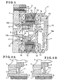
- Fig. 1 is a cross-sectional view illustrating an arrangement of a base member and a housing
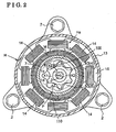
- the outer rotor 5 is rotated around a main axis X1 (a first axis).
- the inner rotor 4 is rotated around a sub axis X2 (a second axis).
- the sub axis X2 is provided at a position displaced at a predetermined distance relative to the main axis X1 so as to be in parallel therewith.
- a hole portion 4a is provided at the inner rotor 4.
- the shaft 3 is inserted into the hole portion 4a so as to rotate relative to the hole portion 4a.
- the shaft 3 and the inner rotor 4 share the sub axis 2.
- Such region is configured to be a negative pressure applied region 100.
- a suction opening portion 1c is provided at a portion of the inner base surface 1a corresponding to the negative pressure applied region 100.
- Positive pressure is applied on a region where the depth of the engagement between the first and second teeth 4G and 5G of the inner and outer rotors 4 and 5 is deepened accompanying the rotation of the inner and outer rotors 4 and 5.
- Such region is configured to be a positive pressure applied region 110.
- a discharge opening portion 1d is provided at a portion of the inner base surface 1a corresponding to the positive pressure applied region 110.
- a second recessed portion 16c is formed at the inner wall surface 16a of the second resin case 16 surrounding the electric power control portion Hb of the housing H.
- the second recessed portion is opened toward the first recessed portion (22) provided at the side plate member (6).
- the second recessed portion 16c is engaged with an outer end of the helical compression spring 24 (outer herein corresponds to toward the right in Fig. 1 ).
- the relief valve R is provided at the side plate member 6. Therefore, oil discharged from the relief valve R sequentially flows from the outer plate surface 6b of the side plate member 6, through the flow space S and the through hole 25 and thereby discharged to the negative pressure applied region 100.
- the relief valve R is arranged by simply processing the side plate member 6, in order to reduce a size of the electric pump. Further, oil flowing through the flow space S contacts the inner wall surface 16a of the electric power control portion Hb of the housing H and thereby cooling the electric power control portion Hb.
Landscapes
- Engineering & Computer Science (AREA)
- Mechanical Engineering (AREA)
- General Engineering & Computer Science (AREA)
- Physics & Mathematics (AREA)
- Fluid Mechanics (AREA)
- Rotary Pumps (AREA)
- Details And Applications Of Rotary Liquid Pumps (AREA)
Applications Claiming Priority (1)
| Application Number | Priority Date | Filing Date | Title |
|---|---|---|---|
| JP2008001482A JP5126588B2 (ja) | 2008-01-08 | 2008-01-08 | 電動ポンプ |
Publications (3)
| Publication Number | Publication Date |
|---|---|
| EP2078859A2 true EP2078859A2 (fr) | 2009-07-15 |
| EP2078859A3 EP2078859A3 (fr) | 2011-08-10 |
| EP2078859B1 EP2078859B1 (fr) | 2012-11-21 |
Family
ID=40551467
Family Applications (1)
| Application Number | Title | Priority Date | Filing Date |
|---|---|---|---|
| EP08022148A Ceased EP2078859B1 (fr) | 2008-01-08 | 2008-12-19 | Pompe électrique |
Country Status (3)
| Country | Link |
|---|---|
| US (1) | US8038423B2 (fr) |
| EP (1) | EP2078859B1 (fr) |
| JP (1) | JP5126588B2 (fr) |
Cited By (7)
| Publication number | Priority date | Publication date | Assignee | Title |
|---|---|---|---|---|
| WO2013037534A1 (fr) * | 2011-09-13 | 2013-03-21 | Robert Bosch Gmbh | Pompe à moteur électrique |
| WO2012071440A3 (fr) * | 2010-11-22 | 2013-06-13 | Micropump, Inc. | Pompes et têtes de pompe ayant une partie qui peut être utilisée sur place et être retirée séparément |
| WO2013167371A3 (fr) * | 2012-05-10 | 2014-04-24 | Robert Bosch Gmbh | Ensemble pompe |
| EP2749737A3 (fr) * | 2012-12-21 | 2016-11-30 | LG Innotek Co., Ltd. | Pompe électrique |
| IT201600130203A1 (it) * | 2016-12-22 | 2018-06-22 | Bosch Gmbh Robert | Pompa elettrica a ingranaggi |
| WO2018130434A1 (fr) * | 2017-01-13 | 2018-07-19 | Continental Automotive Gmbh | Pompe hydraulique, en particulier pour un véhicule automobile |
| EP3708771A1 (fr) * | 2019-03-13 | 2020-09-16 | Jtekt Corporation | Dispositif de pompage |
Families Citing this family (32)
| Publication number | Priority date | Publication date | Assignee | Title |
|---|---|---|---|---|
| DE202009000690U1 (de) * | 2009-01-16 | 2009-04-09 | Gather Industrie Gmbh | Rotationsverdrängerpumpe |
| JP4918936B2 (ja) * | 2009-12-03 | 2012-04-18 | 株式会社デンソー | 電動ポンプ |
| US8376720B2 (en) * | 2010-03-05 | 2013-02-19 | GM Global Technology Operations LLC | Outer ring driven gerotor pump |
| US8821140B2 (en) * | 2010-04-29 | 2014-09-02 | Dan Paval | Gear pump |
| JP5760891B2 (ja) * | 2011-09-17 | 2015-08-12 | 株式会社ジェイテクト | 電動オイルポンプ |
| CN104136779B (zh) * | 2012-02-27 | 2016-10-26 | 麦格纳动力系巴德霍姆堡有限责任公司 | 泵装置 |
| WO2014067545A1 (fr) * | 2012-10-29 | 2014-05-08 | Pierburg Pump Technology Gmbh | Pompe hydraulique électrique d'automobile |
| JP5952723B2 (ja) * | 2012-11-30 | 2016-07-13 | 株式会社日本自動車部品総合研究所 | 回転式ポンプおよびそれを備えたブレーキ装置 |
| AU2013381385B2 (en) * | 2013-03-14 | 2016-08-18 | Allison Transmission, Inc. | Electric pump for a hybrid vehicle |
| CN103244409B (zh) * | 2013-04-24 | 2015-10-07 | 十堰飞骏汽车零部件有限公司 | 无刷电机滚柱泵 |
| DE102014205930A1 (de) * | 2014-03-31 | 2015-10-01 | Continental Automotive Gmbh | Elektrische Maschine |
| US10087927B2 (en) * | 2014-05-01 | 2018-10-02 | Ghsp, Inc. | Electric motor with flux collector |
| US11015585B2 (en) * | 2014-05-01 | 2021-05-25 | Ghsp, Inc. | Submersible pump assembly |
| DE102014226002B4 (de) | 2014-12-16 | 2024-03-14 | Robert Bosch Gmbh | Innenzahnradpumpe |
| ITUB20155909A1 (it) * | 2015-11-25 | 2017-05-25 | Bosch Gmbh Robert | Pompa ad ingranaggi |
| DE102015015863A1 (de) * | 2015-12-09 | 2017-06-14 | Fte Automotive Gmbh | Elektromotorisch angetriebene Flüssigkeitspumpe |
| JP2017166340A (ja) * | 2016-03-14 | 2017-09-21 | 株式会社ミツバ | 電動ポンプ |
| US10514035B2 (en) * | 2016-05-16 | 2019-12-24 | Schaeffler Technologies AG & Co. KG | Integrated eccentric motor and pump |
| US11959481B2 (en) * | 2016-05-27 | 2024-04-16 | Ghsp, Inc. | Thermistor flow path |
| US10914305B2 (en) * | 2016-05-27 | 2021-02-09 | Ghsp, Inc. | Thermistor flow path |
| JP2018096269A (ja) * | 2016-12-13 | 2018-06-21 | 株式会社マーレ フィルターシステムズ | 電動ポンプ |
| US11821420B2 (en) * | 2017-06-30 | 2023-11-21 | Tesla, Inc. | Electric pump system and method |
| DE102017223715A1 (de) * | 2017-12-22 | 2019-06-27 | Magna Powertrain Bad Homburg GmbH | Gerotorpumpe und Verfahren zur Herstellung einer solchen |
| DE102019200560A1 (de) * | 2018-09-14 | 2020-03-19 | Magna Powertrain Bad Homburg GmbH | Gerotorpumpe und Verfahren zur Herstellung eines Druckausgleichs in einer Gerotorpumpe |
| DE102018219354A1 (de) * | 2018-11-13 | 2020-05-14 | Zf Friedrichshafen Ag | Ölpumpenantriebsvorrichtung und Getriebe mit einer solchen Vorrichtung |
| KR102176867B1 (ko) * | 2019-01-29 | 2020-11-10 | 주식회사 디아이씨 | 전동식 오일 펌프 |
| DE102019102745A1 (de) * | 2019-02-04 | 2020-08-06 | Schwäbische Hüttenwerke Automotive GmbH | Innenzahnradpumpe |
| US11168690B2 (en) | 2019-04-11 | 2021-11-09 | Schaeffler Technologies AG & Co. KG | Integrated motor and pump including axially placed coils |
| JP7540262B2 (ja) * | 2020-09-23 | 2024-08-27 | ニデックパワートレインシステムズ株式会社 | 電動ポンプ |
| US11680565B2 (en) * | 2021-02-08 | 2023-06-20 | Schaeffler Technologies AG & Co. KG | Motor-pump system |
| CN114837792A (zh) | 2021-03-10 | 2022-08-02 | 美普盛(上海)汽车零部件有限公司 | 一种带膨胀补偿密封件的电动冷却液泵 |
| JP2022148762A (ja) * | 2021-03-24 | 2022-10-06 | Ntn株式会社 | 電動ポンプ |
Citations (2)
| Publication number | Priority date | Publication date | Assignee | Title |
|---|---|---|---|---|
| JPS60149892A (ja) | 1984-01-13 | 1985-08-07 | Taisei Corp | 蓄熱装置 |
| JP2006336469A (ja) | 2005-05-31 | 2006-12-14 | Hitachi Ltd | モータ一体型内接歯車式ポンプ及びその製造方法並びに電子機器 |
Family Cites Families (18)
| Publication number | Priority date | Publication date | Assignee | Title |
|---|---|---|---|---|
| US2380783A (en) * | 1941-04-07 | 1945-07-31 | Gerotor May Company | Pump structure |
| US2871793A (en) * | 1956-06-29 | 1959-02-03 | Robbins & Myers | Electric motor and pump combination |
| FR1399932A (fr) * | 1964-06-26 | 1965-05-21 | Bosch Gmbh Robert | Machine telle que pompe ou moteur à engrenages |
| US4519755A (en) * | 1980-05-09 | 1985-05-28 | Sargent-Welch Scientific Company | Gerotor vacuum pump |
| JPS5816383U (ja) * | 1981-07-13 | 1983-02-01 | 株式会社不二越 | 内接ギヤポンプ |
| JPS6081489A (ja) * | 1983-10-13 | 1985-05-09 | Honda Motor Co Ltd | ポンプ装置 |
| JPS60149892U (ja) | 1983-11-29 | 1985-10-04 | 本田技研工業株式会社 | 液体圧送用ポンプ装置 |
| JPS6441686A (en) * | 1987-08-06 | 1989-02-13 | Giyuuji Negishi | Trochoid pump |
| DE3900263A1 (de) * | 1989-01-07 | 1990-07-12 | Bosch Gmbh Robert | Aggregat zum foerdern von kraftstoff aus einem vorratstank zur brennkraftmaschine eines kraftfahrzeuges |
| US4971528A (en) * | 1989-03-06 | 1990-11-20 | Stanadyne Automotive Corp. | Lube oil pump with relief valve |
| JPH06200722A (ja) | 1992-12-28 | 1994-07-19 | Suzuki Motor Corp | エンジンのオイルポンプ |
| JPH0942169A (ja) * | 1995-07-31 | 1997-02-10 | Aisin Seiki Co Ltd | ポンプ装置 |
| JPH0968173A (ja) * | 1995-08-29 | 1997-03-11 | Jidosha Kiki Co Ltd | 電動モータ駆動式ポンプ |
| JPH1193862A (ja) * | 1997-09-19 | 1999-04-06 | Jidosha Kiki Co Ltd | 可変容量形ポンプ |
| JP2003129966A (ja) * | 2001-10-24 | 2003-05-08 | Aisin Seiki Co Ltd | 電動オイルポンプ |
| DE10349752B4 (de) * | 2003-10-24 | 2006-04-06 | Voith Turbo Gmbh & Co. Kg | Motorpumpenaggregat |
| JP2005273648A (ja) | 2004-02-23 | 2005-10-06 | Aisin Seiki Co Ltd | 電動ポンプ |
| JP2006233867A (ja) * | 2005-02-24 | 2006-09-07 | Aisin Seiki Co Ltd | 電動ポンプ及び流体供給装置 |
-
2008
- 2008-01-08 JP JP2008001482A patent/JP5126588B2/ja not_active Expired - Fee Related
- 2008-12-19 EP EP08022148A patent/EP2078859B1/fr not_active Ceased
-
2009
- 2009-01-07 US US12/349,651 patent/US8038423B2/en not_active Expired - Fee Related
Patent Citations (2)
| Publication number | Priority date | Publication date | Assignee | Title |
|---|---|---|---|---|
| JPS60149892A (ja) | 1984-01-13 | 1985-08-07 | Taisei Corp | 蓄熱装置 |
| JP2006336469A (ja) | 2005-05-31 | 2006-12-14 | Hitachi Ltd | モータ一体型内接歯車式ポンプ及びその製造方法並びに電子機器 |
Cited By (13)
| Publication number | Priority date | Publication date | Assignee | Title |
|---|---|---|---|---|
| WO2012071440A3 (fr) * | 2010-11-22 | 2013-06-13 | Micropump, Inc. | Pompes et têtes de pompe ayant une partie qui peut être utilisée sur place et être retirée séparément |
| US8876498B2 (en) | 2010-11-22 | 2014-11-04 | Micropump, Inc. | Pumps and pump-heads with separately removable field-serviceable portion |
| WO2013037534A1 (fr) * | 2011-09-13 | 2013-03-21 | Robert Bosch Gmbh | Pompe à moteur électrique |
| WO2013167371A3 (fr) * | 2012-05-10 | 2014-04-24 | Robert Bosch Gmbh | Ensemble pompe |
| CN104271954A (zh) * | 2012-05-10 | 2015-01-07 | 罗伯特·博世有限公司 | 泵单元 |
| US9624929B2 (en) | 2012-12-21 | 2017-04-18 | Lg Innotek Co., Ltd. | Electric pump |
| EP2749737A3 (fr) * | 2012-12-21 | 2016-11-30 | LG Innotek Co., Ltd. | Pompe électrique |
| IT201600130203A1 (it) * | 2016-12-22 | 2018-06-22 | Bosch Gmbh Robert | Pompa elettrica a ingranaggi |
| WO2018114607A1 (fr) * | 2016-12-22 | 2018-06-28 | Robert Bosch Gmbh | Pompe à engrenages électrique |
| CN110100099A (zh) * | 2016-12-22 | 2019-08-06 | 罗伯特·博世有限公司 | 电动齿轮泵 |
| WO2018130434A1 (fr) * | 2017-01-13 | 2018-07-19 | Continental Automotive Gmbh | Pompe hydraulique, en particulier pour un véhicule automobile |
| EP3708771A1 (fr) * | 2019-03-13 | 2020-09-16 | Jtekt Corporation | Dispositif de pompage |
| US11585341B2 (en) | 2019-03-13 | 2023-02-21 | Jtekt Corporation | Pump device |
Also Published As
| Publication number | Publication date |
|---|---|
| US8038423B2 (en) | 2011-10-18 |
| US20090175751A1 (en) | 2009-07-09 |
| JP2009162146A (ja) | 2009-07-23 |
| EP2078859A3 (fr) | 2011-08-10 |
| JP5126588B2 (ja) | 2013-01-23 |
| EP2078859B1 (fr) | 2012-11-21 |
Similar Documents
| Publication | Publication Date | Title |
|---|---|---|
| EP2078859A2 (fr) | Pompe électrique | |
| EP1566545B1 (fr) | Pompe électrique à engrenage intérieur | |
| US8696326B2 (en) | Integrated electrical auxiliary oil pump | |
| JP6369194B2 (ja) | 電動ポンプユニット | |
| US8038417B2 (en) | Electric pump unit and electric oil pump apparatus | |
| US7156623B2 (en) | Electric oil pump apparatus | |
| EP2395631A1 (fr) | Moteur électrique et rotor | |
| EP1600635A2 (fr) | Pompe à engrenage interne à tube d'entrefer | |
| EP2476904A1 (fr) | Unité de pompe électrique | |
| JP5511770B2 (ja) | 電動ポンプ、及び電動ポンプの製造方法 | |
| JP5391016B2 (ja) | 電動ポンプ | |
| CN110836179A (zh) | 电动泵的安装结构 | |
| CN115126692B (zh) | 电动泵 | |
| JP6135225B2 (ja) | ポンプ | |
| CN114251259A (zh) | 电动泵 | |
| JP5803183B2 (ja) | ポンプおよび電動ポンプユニット | |
| JP2015068181A (ja) | 電動ポンプ | |
| JP2012189011A (ja) | ポンプおよび電動ポンプユニット | |
| JP4868851B2 (ja) | 電動モータ | |
| JP5803171B2 (ja) | ポンプ | |
| JP7511438B2 (ja) | 電動オイルポンプ | |
| JP6286656B2 (ja) | トロコイドポンプ | |
| CN212272530U (zh) | 电动油泵 | |
| EP3708771B1 (fr) | Dispositif de pompage | |
| JP2018127978A (ja) | 電動ポンプ |
Legal Events
| Date | Code | Title | Description |
|---|---|---|---|
| PUAI | Public reference made under article 153(3) epc to a published international application that has entered the european phase |
Free format text: ORIGINAL CODE: 0009012 |
|
| AK | Designated contracting states |
Kind code of ref document: A2 Designated state(s): AT BE BG CH CY CZ DE DK EE ES FI FR GB GR HR HU IE IS IT LI LT LU LV MC MT NL NO PL PT RO SE SI SK TR |
|
| AX | Request for extension of the european patent |
Extension state: AL BA MK RS |
|
| PUAL | Search report despatched |
Free format text: ORIGINAL CODE: 0009013 |
|
| AK | Designated contracting states |
Kind code of ref document: A3 Designated state(s): AT BE BG CH CY CZ DE DK EE ES FI FR GB GR HR HU IE IS IT LI LT LU LV MC MT NL NO PL PT RO SE SI SK TR |
|
| AX | Request for extension of the european patent |
Extension state: AL BA MK RS |
|
| RIC1 | Information provided on ipc code assigned before grant |
Ipc: F04C 11/00 20060101ALI20110707BHEP Ipc: F04C 2/10 20060101AFI20110707BHEP |
|
| 17P | Request for examination filed |
Effective date: 20120207 |
|
| AKX | Designation fees paid |
Designated state(s): DE FR |
|
| GRAP | Despatch of communication of intention to grant a patent |
Free format text: ORIGINAL CODE: EPIDOSNIGR1 |
|
| GRAS | Grant fee paid |
Free format text: ORIGINAL CODE: EPIDOSNIGR3 |
|
| GRAA | (expected) grant |
Free format text: ORIGINAL CODE: 0009210 |
|
| AK | Designated contracting states |
Kind code of ref document: B1 Designated state(s): DE FR |
|
| REG | Reference to a national code |
Ref country code: DE Ref legal event code: R096 Ref document number: 602008020190 Country of ref document: DE Effective date: 20130117 |
|
| PLBE | No opposition filed within time limit |
Free format text: ORIGINAL CODE: 0009261 |
|
| STAA | Information on the status of an ep patent application or granted ep patent |
Free format text: STATUS: NO OPPOSITION FILED WITHIN TIME LIMIT |
|
| 26N | No opposition filed |
Effective date: 20130822 |
|
| REG | Reference to a national code |
Ref country code: DE Ref legal event code: R097 Ref document number: 602008020190 Country of ref document: DE Effective date: 20130822 |
|
| REG | Reference to a national code |
Ref country code: FR Ref legal event code: PLFP Year of fee payment: 8 |
|
| PGFP | Annual fee paid to national office [announced via postgrant information from national office to epo] |
Ref country code: DE Payment date: 20151215 Year of fee payment: 8 |
|
| REG | Reference to a national code |
Ref country code: FR Ref legal event code: PLFP Year of fee payment: 9 |
|
| REG | Reference to a national code |
Ref country code: DE Ref legal event code: R119 Ref document number: 602008020190 Country of ref document: DE |
|
| REG | Reference to a national code |
Ref country code: FR Ref legal event code: PLFP Year of fee payment: 10 |
|
| PG25 | Lapsed in a contracting state [announced via postgrant information from national office to epo] |
Ref country code: DE Free format text: LAPSE BECAUSE OF NON-PAYMENT OF DUE FEES Effective date: 20170701 |
|
| PGFP | Annual fee paid to national office [announced via postgrant information from national office to epo] |
Ref country code: FR Payment date: 20191115 Year of fee payment: 12 |
|
| PG25 | Lapsed in a contracting state [announced via postgrant information from national office to epo] |
Ref country code: FR Free format text: LAPSE BECAUSE OF NON-PAYMENT OF DUE FEES Effective date: 20201231 |