EP2077924B1 - Elektrische schere - Google Patents
Elektrische schere Download PDFInfo
- Publication number
- EP2077924B1 EP2077924B1 EP20070820954 EP07820954A EP2077924B1 EP 2077924 B1 EP2077924 B1 EP 2077924B1 EP 20070820954 EP20070820954 EP 20070820954 EP 07820954 A EP07820954 A EP 07820954A EP 2077924 B1 EP2077924 B1 EP 2077924B1
- Authority
- EP
- European Patent Office
- Prior art keywords
- housing
- electric
- gear mechanism
- shears according
- electric motor
- Prior art date
- Legal status (The legal status is an assumption and is not a legal conclusion. Google has not performed a legal analysis and makes no representation as to the accuracy of the status listed.)
- Not-in-force
Links
Images



Classifications
-
- B—PERFORMING OPERATIONS; TRANSPORTING
- B26—HAND CUTTING TOOLS; CUTTING; SEVERING
- B26B—HAND-HELD CUTTING TOOLS NOT OTHERWISE PROVIDED FOR
- B26B29/00—Guards or sheaths or guides for hand cutting tools; Arrangements for guiding hand cutting tools
- B26B29/02—Guards or sheaths for knives
-
- B—PERFORMING OPERATIONS; TRANSPORTING
- B23—MACHINE TOOLS; METAL-WORKING NOT OTHERWISE PROVIDED FOR
- B23D—PLANING; SLOTTING; SHEARING; BROACHING; SAWING; FILING; SCRAPING; LIKE OPERATIONS FOR WORKING METAL BY REMOVING MATERIAL, NOT OTHERWISE PROVIDED FOR
- B23D45/00—Sawing machines or sawing devices with circular saw blades or with friction saw discs
- B23D45/16—Hand-held sawing devices with circular saw blades
-
- B—PERFORMING OPERATIONS; TRANSPORTING
- B25—HAND TOOLS; PORTABLE POWER-DRIVEN TOOLS; MANIPULATORS
- B25B—TOOLS OR BENCH DEVICES NOT OTHERWISE PROVIDED FOR, FOR FASTENING, CONNECTING, DISENGAGING, OR HOLDING
- B25B21/00—Portable power-driven screw or nut setting or loosening tools; Attachments for drilling apparatus serving the same purpose
-
- B—PERFORMING OPERATIONS; TRANSPORTING
- B25—HAND TOOLS; PORTABLE POWER-DRIVEN TOOLS; MANIPULATORS
- B25B—TOOLS OR BENCH DEVICES NOT OTHERWISE PROVIDED FOR, FOR FASTENING, CONNECTING, DISENGAGING, OR HOLDING
- B25B23/00—Details of, or accessories for, spanners, wrenches, screwdrivers
- B25B23/18—Devices for illuminating the head of the screw or the nut
-
- B—PERFORMING OPERATIONS; TRANSPORTING
- B25—HAND TOOLS; PORTABLE POWER-DRIVEN TOOLS; MANIPULATORS
- B25F—COMBINATION OR MULTI-PURPOSE TOOLS NOT OTHERWISE PROVIDED FOR; DETAILS OR COMPONENTS OF PORTABLE POWER-DRIVEN TOOLS NOT PARTICULARLY RELATED TO THE OPERATIONS PERFORMED AND NOT OTHERWISE PROVIDED FOR
- B25F5/00—Details or components of portable power-driven tools not particularly related to the operations performed and not otherwise provided for
- B25F5/02—Construction of casings, bodies or handles
-
- B—PERFORMING OPERATIONS; TRANSPORTING
- B26—HAND CUTTING TOOLS; CUTTING; SEVERING
- B26B—HAND-HELD CUTTING TOOLS NOT OTHERWISE PROVIDED FOR
- B26B25/00—Hand cutting tools involving disc blades, e.g. motor-driven
-
- B—PERFORMING OPERATIONS; TRANSPORTING
- B26—HAND CUTTING TOOLS; CUTTING; SEVERING
- B26B—HAND-HELD CUTTING TOOLS NOT OTHERWISE PROVIDED FOR
- B26B29/00—Guards or sheaths or guides for hand cutting tools; Arrangements for guiding hand cutting tools
-
- H—ELECTRICITY
- H01—ELECTRIC ELEMENTS
- H01M—PROCESSES OR MEANS, e.g. BATTERIES, FOR THE DIRECT CONVERSION OF CHEMICAL ENERGY INTO ELECTRICAL ENERGY
- H01M50/00—Constructional details or processes of manufacture of the non-active parts of electrochemical cells other than fuel cells, e.g. hybrid cells
- H01M50/20—Mountings; Secondary casings or frames; Racks, modules or packs; Suspension devices; Shock absorbers; Transport or carrying devices; Holders
- H01M50/204—Racks, modules or packs for multiple batteries or multiple cells
- H01M50/207—Racks, modules or packs for multiple batteries or multiple cells characterised by their shape
- H01M50/213—Racks, modules or packs for multiple batteries or multiple cells characterised by their shape adapted for cells having curved cross-section, e.g. round or elliptic
-
- Y—GENERAL TAGGING OF NEW TECHNOLOGICAL DEVELOPMENTS; GENERAL TAGGING OF CROSS-SECTIONAL TECHNOLOGIES SPANNING OVER SEVERAL SECTIONS OF THE IPC; TECHNICAL SUBJECTS COVERED BY FORMER USPC CROSS-REFERENCE ART COLLECTIONS [XRACs] AND DIGESTS
- Y02—TECHNOLOGIES OR APPLICATIONS FOR MITIGATION OR ADAPTATION AGAINST CLIMATE CHANGE
- Y02E—REDUCTION OF GREENHOUSE GAS [GHG] EMISSIONS, RELATED TO ENERGY GENERATION, TRANSMISSION OR DISTRIBUTION
- Y02E60/00—Enabling technologies; Technologies with a potential or indirect contribution to GHG emissions mitigation
- Y02E60/10—Energy storage using batteries
-
- Y—GENERAL TAGGING OF NEW TECHNOLOGICAL DEVELOPMENTS; GENERAL TAGGING OF CROSS-SECTIONAL TECHNOLOGIES SPANNING OVER SEVERAL SECTIONS OF THE IPC; TECHNICAL SUBJECTS COVERED BY FORMER USPC CROSS-REFERENCE ART COLLECTIONS [XRACs] AND DIGESTS
- Y10—TECHNICAL SUBJECTS COVERED BY FORMER USPC
- Y10T—TECHNICAL SUBJECTS COVERED BY FORMER US CLASSIFICATION
- Y10T83/00—Cutting
- Y10T83/828—With illuminating or viewing means for work
Definitions
- the invention is based on an electric scissors, according to the preamble of claim 1.
- a known electric scissors for cutting sheet material such as fabrics, paper and board webs and the like.
- ( SU 1 768 384 A1 ) has an elongated housing with a tool head and a handle part.
- a transverse to the housing longitudinal axis aligned drive shaft is mounted, which protrudes laterally from the tool head.
- On the drive shaft a disk-shaped polygonal cutting wheel is taken against rotation, which is covered in working position upwardly facing edge over more than 180 ° circumferential angle of a housing formed on the protective collar.
- On the tool head a downwardly projecting angular knife holder is mounted, which carries a cooperating with the cutting wheel counter blade and on which a lower edge region of the cutting wheel opposite support foot is formed.
- the knife holder is arranged on the housing so that the support surface of the support foot and the longitudinal axis of the housing form an acute angle.
- an electric motor and a gear for driving the cutting wheel bearing drive shaft are arranged in the handle part. The power supply of the electric motor via an electrical device cable.
- a well-known universal cutting device for flat materials such as wallpapers and floor coverings, ( DE 197 04 688 C1 ) has a cooperating with a counter blade, rotating cutting disc, on the periphery of a plurality of straight blades are juxtaposed secant to form a polygon.
- the cutting disc is driven by a battery-powered electric motor, which is accommodated in a two-part, bent, tubular housing, wherein the battery in a designed as a handle part rear housing part and the electric motor in one of them angled, to the rear
- Housing part attached front housing part is housed.
- a projecting blade carrier is arranged, on which the cutting disc is mounted by means of a transverse to the housing axis oriented drive shaft and the counter blade is attached.
- the drive shaft is coupled via a transmission to the output shaft of the electric motor.
- the handle part accessible to the housing actuator for a circuit arranged in the electric motor electrical switch to the on and off switch of the electric motor is present.
- a well-known cordless screwdriver ( DE 10 2004 051 913 A1 or DE 203 21 137 U1 or DE 10 2004 038 788 A1 ) Has a pistol-like housing, which has a motor housing accommodating an electric motor and a handle bent therefrom with an on / off switch for the electric motor and a firmly inserted, designed as a lithium-ion cell battery.
- the housing with motor housing and handle is composed of two adjacent in a central plane shells.
- the battery is arranged on a longitudinal side of the handle extending parallel to the board and contacted with this.
- the on / off switch is contacted by means of contact lugs on the remote from the battery longitudinal side of the board.
- the accessible on the front of the handle on / off switch is a large button.
- a structured handle pad On the side facing away from the front back of the handle a structured handle pad is attached.
- the output shaft of the electric motor is coupled via a gearbox to a coaxial with the output shaft drive spindle, which is configured as a hexagon socket for receiving matching standard bits.
- Gear and drive spindle are accommodated in a gear housing, which is attached as a separate, one-piece component to the remote from the handle front end of the motor housing.
- a well-known cordless impact wrench ( DE 10 2004 032 788 A1 ) has a pistol-shaped housing with a handle, at its pointing in the direction of the front a switch button for switching on and off of a battery powered by an electric motor is arranged.
- the electric motor is received in the angled from the handle housing portion and drives a coaxial with the axis of the housing portion and the output shaft of the electric motor drive spindle, which has a hexagonal socket for inserting a fferbits at its free end.
- the battery is detachably attached to the end of the handle facing away from the housing receiving the electric motor.
- a known rotary shear ( US 3,906,629 ) has a tubular power grip, in which an electric motor is accommodated.
- the electric motor has a coaxial to the handle axis Output shaft, at the end of a worm gear is arranged.
- the worm gear is accommodated in a cutting head attached to the power grip. On the cutting head driven via the worm gear cutting wheel and a cooperating with this rotating plants redesignrad are rotatably held.
- a well-known kebab cutting machine ( DE 10 2005 001 774 A1 ) has a rotating circular blade which sits on a driven by an electric motor via a gear shaft. Electric motor and circular blade are accommodated in a housing from which the circular blade protrudes partially. On the housing a right angle outgoing handle with an on / off switch is attached, wherein the handle relative to the housing by an angle pivotally and in the pivot position can be fixed.
- a well-known hand saw machine ( US 2001/0029819 A1 ) has a lamp for illuminating a part of the workpiece when performing a sawing work.
- the lamp is arranged on a protective blade covering the rotating saw blade so that it is laterally offset from the saw blade.
- the electric scissors according to the invention has the advantage of being compact, compact and lightweight and thereby allow fatigue-free working.
- the housing consists only of the tool head and the integral handle portion and accommodates all necessary components, including the wireless power supply.
- the displacement of the electric motor and the gear in the tool head not only creates space for the energy storage and electronics, but also places the focus of the power tool very far down in the tool head and thus closer to the workpiece, which improves the ergonomics of handling.
- the ergonomics is significantly improved by the fact that the housing is designed banana-like curved, whereby the handle is clearly spaced in an ergonomic position from the surface of the workpiece to be machined, so that the fingers of the hand tool operator at any time of working with the Workpiece surface can come into contact.
- the arrangement of the electrical switch of the on / off switch on an integrated circuit in the handle electronics board and designed as lithium-ion battery, volume-thin energy storage above the electronic board and the recording of the output shaft on the one hand in a pressed into a housing shell Bearings and on the other hand in a sintered bush pressed into the other housing shell contribute to a smaller construction volume and a low weight of the electric scissors and also allow cost-effective production of the scissors to comply with low production costs.
- the electric scissors also called electrical utility knife, shown in the drawing in various views and sections, serves as an exemplary embodiment.
- the disk-shaped rotary tool 11 is a polygonal cutting wheel 12, more precisely a 10-edge cutting wheel.
- the electric scissors has a housing 13, which is composed of two housing shells 131, 132.
- the housing 13 comprises a tool head 14, on which the rotary tool 11 is arranged laterally and an adjoining handle portion 15.
- Tool head 14 and handle portion 15 are integrally formed with each other, so that each housing shell 131, 132 each part of the tool head 14 and the handle part 15 forms.
- a transverse to the housing longitudinal axis aligned drive shaft 16 is rotatably mounted in a flattened area 17 (FIG.
- the in Fig. 1 front housing shell 132 protrudes from the tool head 14 with a protruding and here receives the rotary tool 11.
- the drive shaft 16 is driven by an electric motor 18 via a transmission 19 (FIG. Fig. 2 ) rotationally driven.
- Gear 19 and electric motor 18 are arranged in the tool head 14.
- the electric motor 18 is fed by a rechargeable, volume-thin energy storage 20 with high charging capacity.
- a lithium-ion battery is preferred, so that in the following the energy storage is called short battery 20.
- the battery 20 is integrated together with an electronic board 21 and an on / off switch 22 for the electric scissors in the grip part 15 of the housing 13. In this case, the battery 20 is arranged above the electronic board 21.
- the on / off switch 22 consists of a circuit arranged in the battery 20 and electric motor 18, not shown here, arranged on the electronic board 21, electrical switch and an actuator 23, which is designed as a large button 24, which on the underside of the handle part Protrudes 15 and arranged on a arranged on the underside of the electronic board 21 stamp 25 actuates the electrical switch ( Fig. 3 ).
- the button 24 is pivotally mounted in the handle portion 15 and held by a return spring 26 in a position of the on-off switch 22. Due to the pivotal mounting of the button 24 is advantageous for the electrical switch a short and for the return spring 26, a long stroke.
- the large area of the button 24 allows an ergonomically advantageous operation of the on / off switch 22 by the operator.
- a circuit for charging and monitoring the state of charge of the battery 20 is arranged on the electronic board 21, a circuit for charging and monitoring the state of charge of the battery 20 is arranged.
- a state of charge indicator 28 is arranged, which is also connected to the circuit.
- the state of charge indicator 28 is arranged on the upper side of the handle part 15 facing the end of the tool head 14 ( Fig. 1 to 3 ).
- the battery 20 is contacted by means of terminal lugs 29 and the electric motor 18 by means of terminal lugs 30 on the electronic board 21.
- a grip pad 32 is attached with a golfball-like structure ( Fig. 1 ). The grip pad 32 allows a non-slip, secure holding and guiding the electric scissors.
- the arranged in the tool head 14 gear 19 consists of a reduction gear and a downstream in the power flow deflection gear ( Fig. 3 and 4 ).
- the reduction gear is designed as a multi-stage, in the exemplary embodiment two-stage planetary gear 34 with an input stage and an output stage and the reversing gear as a bevel gear 35, the two intermeshing, with the wheel axes at right angles to each other aligned bevel gears 36, 37 has.
- the input stage of the planetary gear 34 is coupled to the motor shaft 33 of the electric motor 18 and the output stage of the planetary gear 34 to the first bevel gear 36 of the bevel gear 35.
- the two bevel gears 36, 37 have the same number of teeth and are made of brass.
- the first bevel gear 36 is received in a fixed ball bearing 38 in the housing 13 and the second bevel gear 37 is pressed onto the drive shaft 16.
- the drive shaft 16 itself is on the one hand in a ball bearing 39, which exercises a fixed bearing function, and on the other hand in a sintered bushing 40 (FIG. Fig. 4 ) stored.
- the sintered bushing 40 is pressed into the housing shell 131 and the ball bearing 39 into the housing shell 132.
- each gear stage has a sun gear 42, with the sun gear 42 and the ring gear 41 meshing planetary gears 43 (in the embodiment, three planetary gears 43) and a planetary gear carrier 44 carrying the planetary gears 43.
- the sun gear 42 of the input stage is secure with respect to the motor shaft 33 plugged while the sun gear 42 of the output stage is part of the Planetenradlys 44 of the input stage. If the planetary gear 35 has more than two gear stages, the sun gear 42 of the next gear stage is fastened or integrally formed with each planet gear carrier 44.
- the sun gear 42 of the intermediate gear stage would then be combined with the planet carrier 41 of the input stage and the sun gear 42 of the output stage with the planet gear carrier 44 of the middle gear stage.
- the Planentenradley 44 of the output stage is fixed on a pin-like output shaft 58 on which the first bevel gear 36 of the bevel gear 35 is non-rotatably mounted.
- the planet gears 43 of the gear stages are made of sintered steel, and the ring gear 41 is a sintered part, which contributes to weight and cost savings.
- the in the flattened portion 17 of the tool head 14 from the housing 13, more precisely from the housing shell 132, laterally projecting shaft portion of the drive shaft 16 has a support flange 45 (FIG. Fig.
- an angle-shaped blade holding plate 49 is releasably attached ( Fig. 1 and 4 ).
- a support foot 50 is formed, with which the electric scissors can be performed when cutting on a management level.
- a rectangular counter knife 51 is arranged, which with the rotary tool 11 and the polygonal cutting wheel 12, a wedge gap 52 (FIG. Fig. 1
- the counter knife 51 is riveted on a leaf spring 53, which in turn on the in Fig. 1 not visible side of the support foot 50 is attached.
- the blade holding plate 49 is detachably held on the housing shell 132 and can - as not shown here - are exchanged for a sprung guard.
- This protective bar covers the lower edge area of the rotary tool 11 or polygonal cutting wheel 12 released by the knife holding plate 49 and serves to protect against contact when the electric scissors are not in use. With this guard can be performed without counter blade 51 with the electric scissors cutting.
- a protective hood 54 is pivotally mounted ( Fig. 1 ).
- the protective cover 54 covers the upper edge region of the rotary tool 11 facing away from the support foot 50 so that it can not be touched.
- the extension angle of the protective hood 54 is more than 180 °.
- the guard 54 is spring-loaded, and pushes when not in use of the electric scissors on the wedge-shaped gap 52, so that the turning tool 11 is completely covered at the edge of support foot 50 and guard 54.
- the protective cover 54 is coupled to the on / off switch 22 so that upon actuation of the button 24 to turn on the electric motor 18, the protective cover 54 in Fig.
- the protective cover 54 may also be integrally formed on the housing shell 132, wherein its overlap region for the rotary tool 11 ends in front of the wedge gap 52.
- a suspension lug 55 is formed instead of a hanging loop 55 but also a storage bar on the housing 13 may be formed.
- Fig. 2 and 3 show, in the working direction facing front side of the tool head 15 at least one electric lamp is arranged, which is preferably formed as an LED 56.
- the LED 56 is guided via a connecting line 57 to the electronic board 21 and connected there to the circuit.
- the electrical switch of the on / off switch 22 is formed in two stages, with the operation of the button 24, the electrical switch is successively transferred in stage "1" and stage "2".
- the LED 56 can also be connected to a separate, accessible to the housing 13 switches, so that the LED 56 can be switched on and off independently of the commissioning of the electric scissors. In this case, the electric scissors can also be used as a flashlight.
Landscapes
- Engineering & Computer Science (AREA)
- Mechanical Engineering (AREA)
- Life Sciences & Earth Sciences (AREA)
- Forests & Forestry (AREA)
- Chemical & Material Sciences (AREA)
- Chemical Kinetics & Catalysis (AREA)
- Electrochemistry (AREA)
- General Chemical & Material Sciences (AREA)
- Scissors And Nippers (AREA)
- Sawing (AREA)
- Drilling And Boring (AREA)
- Harvester Elements (AREA)
Abstract
Description
- Die Erfindung geht aus von einer elektrischen Schere, nach dem Oberbegriff des Anspruchs 1.
- Eine bekannte elektrische Schere zum Schneiden von Blattmaterial, wie Stoffe, Papier- und Kartonbahnen und dgl., (
SU 1 768 384 A1 - Eine bekannte Universal-Schneidvorrichtung für flächige Materialien, wie Tapeten und Fußbodenbeläge, (
DE 197 04 688 C1 ) weist eine mit einem Gegenmesser zusammenwirkende, rotierende Schneidscheibe auf, auf deren Peripherie eine Vielzahl von geraden Schneiden sekantiell unter Ausbildung eines Vielecks aneinandergereiht sind. Die Schneidscheibe wird von einem akkugespeisten Elektromotor angetrieben, der in einem zweiteiligen, abgeknickten, rohrförmigen Gehäuse aufgenommen ist, wobei der Akku in einem als Griffteil ausgebildeten hinteren Gehäuseteil und der Elektromotor in einem davon abgewinkelten, an das hintere - Gehäuseteil angesetzten vorderen Gehäuseteil untergebracht ist. Am freien Ende des vorderen Gehäuseteils ist ein vorstehender Messerträger angeordnet, an dem die Schneidscheibe mittels einer quer zur Gehäuseachse ausgerichteten Antriebswelle gelagert und das Gegenmesser befestigt ist. Die Antriebswelle ist über ein Getriebe mit der Abtriebswelle des Elektromotors gekoppelt. Im Griffteil ist ein am Gehäuse zugängliches Betätigungselement für einen im Stromkreis des Elektromotors angeordneten elektrischen Schalter zum Ein- und Ausschalter des Elektromotors vorhanden.
- Ein bekannter Akkuschrauber (
DE 10 2004 051 913 A1 oderDE 203 21 137 U1 oderDE 10 2004 038 788 A1 ) weist ein pistolenartiges Gehäuse auf, das ein einen Elektromotor aufnehmendes Motorgehäuse und einen davon abgewinkelten Handgriff mit einem Ein-/Ausschalter für den Elektromotor und einem fest eingesetzten, als Lithium-Ionen-Zelle ausgebildeten Akku aufweist. Das Gehäuse mit Motorgehäuse und Handgriff ist aus zwei in einer Mittenebene aneinanderliegenden Halbschalen zusammengesetzt. Der Akku ist auf einer zur Längsseite des Handgriffs sich parallel erstreckende Platine angeordnet und mit dieser kontaktiert. Der Ein-/Ausschalter ist mittels Kontaktfahnen auf die vom Akku abgekehrte Längsseite der Platine kontaktiert. Der an der Vorderseite des Handgriffs zugängliche Ein-/Ausschalter ist eine großflächige Taste. Auf der von der Vorderseite abgekehrten Rückseite des Handgriffs ist ein strukturierter Handgriffbelag befestigt. Die Abtriebswelle des Elektromotors ist über ein Getriebe auf eine mit der Abtriebswelle koaxiale Antriebsspindel gekoppelt, die stirnseitig als Innensechskant zur Aufnahme passender Standardbits ausgestaltet ist. Getriebe und Antriebsspindel sind in einem Getriebegehäuse aufgenommen, das als separates, einteiliges Bauteil an das vom Handgriff abgekehrte Stirnende des Motorgehäuses angesetzt ist. - Ein bekannter Akku-Schlagschrauber (
DE 10 2004 032 788 A1 ) weist ein pistolenförmiges Gehäuse mit einem Handgriff auf, an dessen in Arbeitsrichtung weisender Vorderseite eine Schalttaste zum Ein- und Ausschalten eines von einem Akku gespeisten Elektromotors angeordnet ist. Der Elektromotor ist in dem vom Handgriff abgewinkelten Gehäusebereich aufgenommen und treibt eine mit der Achse des Gehäusebereichs und der Abtriebswelle des Elektromotors koaxiale Antriebsspindel an, die an ihrem freien Ende eine Sechskantaufnahme zum Einstecken eines Schraubbits besitzt. Der Akku ist an dem von dem den Elektromotor aufnehmenden Gehäusebereich abgekehrten Ende des Handgriffs lösbar angesetzt. - Eine bekannte Rotationsschere (
US 3 906 629 ) weist einen rohrförmigen Powergriff auf, in dem ein Elektromotor aufgenommen ist. Der Elektromotor hat eine zur Griffachse koaxiale Abtriebswelle, an deren Ende ein Schneckengetriebe angeordnet ist. Das Schneckengetriebe ist in einem am Powergriff angesetzten Schneidkopf aufgenommen. Am Schneidkopf sind ein über das Schneckengetriebe angetriebenes Schneidrad und ein mit diesem zusammenwirkendes rotierendes Gegenscheidrad drehbar gehalten. - Eine bekannte Döner-Schneidemaschine (
DE 10 2005 001 774 A1 ) weist ein rotierendes Kreismesser auf, das auf einer von einem Elektromotor über ein Getriebe angetriebenen Messerwelle sitzt. Elektromotor und Kreismesser sind in einem Gehäuse aufgenommen, aus dem das Kreismesser teilweise herausragt. Am Gehäuse ist ein rechtwinklig abgehender Handgriff mit einem Ein-/Ausschalter befestigt, wobei der Handgriff gegenüber dem Gehäuse um einen Winkel schwenkbar und in der Schwenkposition festsetzbar ist. - Eine bekannte Handkreissägemaschine (
US 2001/0029819 A1 ) weist eine Lampe zur Beleuchtung eines Teils des Werkstücks bei Durchführung einer Sägearbeit auf. Die Lampe ist an einer das rotierende Sägeblatt abdeckenden Schutzhaube so angeordnet, dass sie seitlich zum Sägeblatt versetzt ist. - Die erfindungsgemäße elektrische Schere, mit den Merkmalen des Anspruchs 1 hat den Vorteil, kompakt, bauklein und leichtgewichtig zu sein und dadurch ein ermüdungsfreies Arbeiten zu ermöglichen. Das Gehäuse besteht nur aus dem Werkzeugkopf und dem damit einstückigen Griffteil und nimmt alle erforderlichen Komponenten, einschließlich der kabellosen Stromversorgung, auf. Die Verlagerung des Elektromotors und des Getriebes in den Werkzeugkopf schafft nicht nur Platz für den Energiespeicher und die Elektronik, sondern legt auch den Schwerpunkt der Handwerkzeugmaschine sehr weit nach unten in den Werkzeugkopf und damit näher zum Werkstück, was die Ergonomie der Handhabung verbessert. Die Ergonomie ist noch dadurch wesentlich verbessert, dass das Gehäuse bananenähnlich gekrümmt ausgeführt ist, wodurch der Griffteil in einer ergonomisch günstige Stellung von der Oberfläche des zu bearbeitenden Werkstücks deutlich beabstandet ist, so dass die Finger des die Handwerkzeugmaschine Bedienenden zu keinem Zeitpunkt des Arbeitens mit der Werkstückoberfläche in Berührung kommen kann. Die Anordnung des elektrischen Schalters des Ein-/Ausschalters auf einer im Griffteil integrierten Elektronikplatine und des als Lithium-Ionen-Akku ausgebildeten, volumenkleinen Energiespeichers oberhalb der Elektronikplatine sowie die Aufnahme der Abtriebswelle einerseits in einem in die eine Gehäuseschale eingepressten Kugellager und andererseits in einer in die andere Gehäuseschale eingepressten Sinterbuchse tragen zu einem kleineren Bauvolumen und einem geringen Gewicht der elektrischen Schere bei und ermöglichen darüber hinaus eine kostengünstige Herstellung der Schere zur Einhaltung niedriger Gestehungskosten.
- Durch die in den weiteren Ansprüchen aufgeführten Maßnahmen sind vorteilhafte Weiterbildungen und Verbesserungen der im Anspruch 1 angegebenen Handwerkzeugmaschine möglich.
- Die erfindungsgemäße elektrische Schere ist anhand eines in der Zeichnung dargestellten Ausführungsbeispiels in der nachfolgenden Beschreibung näher erläutert. Es zeigen:
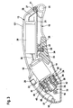
- Fig. 1
- eine Seitenansicht einer elektrischen Schere,
- Fig. 2
- eine perspektivische Seitenansicht der elektrischen Schere in
Fig. 1 nach Entfernen einer Gehäuseschale des Gehäuses und eines Griffbelags, - Fig. 3
- einen Längsschnitt der elektrischen Schere gemäß der in
Fig. 2 mit III - III angedeuteten Schnittebene, - Fig. 3
- einen Längsschnitt der elektrischen Schere gemäß der in
Fig. 2 mit III - III angedeuteten Schnittebene, - Fig. 4
- einen Schnitt längs der Linie IV - IV in
Fig. 3 . - Die in der Zeichnung in verschiedenen Ansichten und Schnitten dargestellte elektrische Schere, auch elektrisches Universalmesser genannt, dient als Ausführungsbeispiel. Im Ausführungsbeispiel der elektrischen Schere ist das scheibenförmige Drehwerkzeug 11 ein Mehrkant-Schneidrad 12, genauer ein 10-Kant-Schneidrad. Die elektrische Schere weist ein Gehäuse 13 auf, das aus zwei Gehäuseschalen 131, 132 zusammengesetzt ist. Das Gehäuse 13 umfasst einen Werkzeugkopf 14, an dem das Drehwerkzeug 11 seitlich angeordnet ist und einen sich daran anschließenden Griffteil 15. Werkzeugkopf 14 und Griffteil 15 sind einstückig miteinander ausgebildet, so dass jede Gehäuseschale 131, 132 jeweils einen Teil des Werkzeugkopfes 14 und des Griffteils 15 bildet. Im Werkzeugkopf 14 ist eine quer zur Gehäuselängsachse ausgerichtete Antriebswelle 16 drehbar gelagert, die in einem abgeflachten Bereich 17 (
Fig. 4 ) der inFig. 1 vorderen Gehäuseschale 132 aus dem Werkzeugkopf 14 mit einem Vorstehende herausragt und hier das Drehwerkzeug 11 aufnimmt. Die Antriebswelle 16 wird von einem Elektromotor 18 über ein Getriebe 19 (Fig. 2 ) rotatorisch angetrieben. Getriebe 19 und Elektromotor 18 sind im Werkzeugkopf 14 angeordnet. Der Elektromotor 18 wird von einem aufladbaren, volumenkleinen Energiespeicher 20 mit hoher Ladekapazität gespeist. Als ein solcher Energiespeicher wird ein Lithium-Ionen-Akku bevorzugt, so dass im folgenden der Energiespeicher kurz Akku 20 genannt wird. Der Akku 20 ist zusammen mit einer Elektronikplatine 21 und einem Ein-/Ausschalter 22 für die elektrische Schere im Griffteil 15 des Gehäuses 13 integriert. Dabei ist der Akku 20 oberhalb der Elektronikplatine 21 angeordnet. Der Ein-/Ausschalter 22 besteht aus einem im Stromkreis von Akku 20 und Elektromotor 18 angeordneten, hier nicht dargestellten, auf der Elektronikplatine 21 angeordneten, elektrischen Schalter und einem Betätigungselement 23, das als großflächige Taste 24 ausgebildet ist, die auf der Unterseite des Griffteils 15 vorsteht und über einen an der Unterseite der Elektronikplatine 21 angeordneten Stempel 25 den elektrischen Schalter betätigt (Fig. 3 ). Die Taste 24 ist schwenkbar im Griffteil 15 gelagert und durch eine Rückstellfeder 26 in einer Ausposition des Ein-Ausschalters 22 gehalten. Durch die Schwenklagerung der Taste 24 ergibt sich vorteilhaft für den elektrischen Schalter ein kurzer und für die Rückstellfeder 26 ein langer Hub. Die Großflächigkeit der Taste 24 ermöglicht ein ergonomisch vorteilhaftes Betätigen des Ein-/Ausschalters 22 durch den Bediener. - Auf der Elektronikplatine 21 ist eine Schaltung zum Laden und Überwachen des Ladezustands des Akkus 20 angeordnet. Eine auf der Elektronikplatine 21 befestigte Ladebuchse 27, die durch eine Aussparung 31 am hinteren Ende des Griffteils 15 für einen Ladestecker eines Ladegeräts zugänglich ist, ist mit der Schaltung verbunden. In einem in der Arbeitsstellung der elektrischen Schere für den Bediener sichtbaren Bereich des Gehäuses 13 ist eine Ladezustandsanzeige 28 angeordnet, die ebenfalls an der Schaltung angeschlossen ist. Im dargestellten Ausführungsbeispiel ist die Ladezustandsanzeige 28 auf der Oberseite des dem Griffteil 15 zugekehrten Endes des Werkzeugskopfes 14 angeordnet (
Fig. 1 bis 3 ). Der Akku 20 ist mittels Anschlussfahnen 29 und der Elektromotor 18 mittels Anschlussfahnen 30 auf die Elektronikplatine 21 kontaktiert. Auf der von der Taste 24 abgekehrten Oberseite des Griffteils 15 ist ein Griffbelag 32 mit einer golfballähnlichen Struktur befestigt (Fig. 1 ). Der Griffbelag 32 ermöglicht ein rutschfestes, sicheres Halten und Führen der elektrischen Schere. - Das im Werkzeugkopf 14 angeordnete Getriebe 19 besteht aus einem Reduziergetriebe und einem im Kraftfluss nachgeordneten Umlenkgetriebe (
Fig. 3 und4 ). Eine solche Getriebezusammensetzung lässt sich recht bauklein ausführen. Das Reduziergetriebe ist als mehrstufiges, im Ausführungsbeispiel zweistufiges Planetengetriebe 34 mit einer Eingangsstufe und einer Ausgangsstufe und das Umlenkgetriebe als Kegelradgetriebe 35 ausgebildet, das zwei miteinander kämmende, mit den Radachsen rechtwinklig zueinander ausgerichtete Kegelräder 36, 37 aufweist. Die Eingangsstufe des Planetengetriebes 34 ist an die Motorwelle 33 des Elektromotors 18 und die Ausgangsstufe des Planentengetriebes 34 an das erste Kegelrad 36 des Kegelradgetriebes 35 angekoppelt. Die beiden Kegelräder 36, 37 weisen eine gleiche Zahnzahl auf und sind aus Messing gefertigt. Das erste Kegelrad 36 ist in einem im Gehäuse 13 festgelegten Kugellager 38 aufgenommen und das zweite Kegelrad 37 ist auf die Antriebswelle 16 aufgepresst. Die Antriebswelle 16 selbst ist einerseits in einem Kugellager 39, das eine Festlagerfunktion ausübt, und andererseits in einer Sinterbuchse 40 (Fig. 4 ) gelagert. Die Sinterbuchse 40 ist in die Gehäuseschale 131 und das Kugellager 39 in die Gehäuseschale 132 eingepresst. - Im Planetengetriebe 34 haben alle Getriebestufen ein gemeinsames, im Gehäuse 13 festgelegtes Hohlrad 41, das sich über die Axiallänge des Planetengetriebes 34 erstreckt. Jede Getriebestufe weist ein Sonnenrad 42, mit dem Sonnenrad 42 und dem Hohlrad 41 kämmende Planetenräder 43 (im Ausführungsbeispiel jeweils drei Planentenräder 43) und einen die Planetenräder 43 tragenden Planetenradträger 44 auf. Das Sonnenrad 42 der Eingangsstufe ist mitnahmesicher auf die Motorwelle 33 aufgesteckt, während das Sonnenrad 42 der Ausgangsstufe Teil des Planetenradträgers 44 der Eingansstufe ist. Hat das Planetengetriebe 35 mehr als zwei Getriebestufen, so ist an jedem Planetenradträger 44 das Sonnenrad 42 der nächsten Getriebestufe befestigt bzw. einstückig mit diesem ausgebildet. Bei drei Getriebestufen wäre dann das Sonnenrad 42 der mittleren Getriebestufe mit dem Planetenradträger 41 der Eingangsstufe und das Sonnenrad 42 der Ausgangsstufe mit dem Planetenradträger 44 der mittleren Getriebestufe vereinigt. Der Planentenradträger 44 der Ausgangsstufe ist auf einer zapfenartigen Abtriebswelle 58 fixiert, auf der das erste Kegelrad 36 des Kegelradgetriebes 35 undrehbar sitzt. Die Planetenräder 43 der Getriebestufen sind aus Sinterstahl gefertigt, und das Hohlrad 41 ist ein Sinterteil, was zur Gewichts- und Kosteneinsparung beiträgt. Der im abgeflachten Bereich 17 des Werkzeugkopfes 14 aus dem Gehäuse 13, genauer aus der Gehäuseschale 132, seitlich herausragende Wellenabschnitt der Antriebswelle 16 weist einen Auflageflansch 45 (
Fig. 2 und4 ) mit einer daran ausgebildeten Drehmitnahme 46 (Fig. 1 ) für das Drehwerkzeug 11 auf. In der Antriebswelle 16 ist ein von ihrem freien Stirnende her eingebrachte, axiale Gewindebohrung 47 vorhanden. In die Gewindebohrung 47 ist eine Flachkopfschraube 48 (Fig. 1 und4 ) eingeschraubt, die das auf dem Auflageflansch 45 drehfest aufliegende, scheibenförmige Drehwerkzeug 11, hier Mehrkant-Schneidrad 12, axial sichert - Am Gehäuse 13, genauer an der Gehäuseschale 132, ist im abgeflachten Bereich 17, der etwas größer ausgebildet ist als der Durchmesser des Drehwerkzeugs 11, ein winkelförmiges Messerhalteblech 49 lösbar befestigt (
Fig. 1 und4 ). Am Messerhalteblech 49 ist ein Auflagefuß 50 ausgebildet, mit dem die elektrische Schere beim Schneiden auf einer Führungsebene geführt werden kann. Etwa parallel zu der Auflagefläche 501 des Auflagefußes 50 ist ein rechteckförmiges Gegenmesser 51 angeordnet, das mit dem Drehwerkzeug 11 bzw. dem Mehrkant-Schneidrad 12 einen Keilspalt 52 (Fig. 1 ) einschließt, dessen Öffnung in Arbeitsrichtung weist Das Gegenmesser 51 ist auf einer Blattfeder 53 aufgenietet, die ihrerseits auf der inFig. 1 nicht zu sehenden Seite des Auflagefußes 50 befestigt ist. - Das Messerhalteblech 49 ist lösbar an der Gehäuseschale 132 gehalten und kann - wie hier nicht dargestellt ist - gegen einen angefederten Schutzbügel ausgetauscht werden. Dieser Schutzbügel überdeckt den vom Messerhalteblech 49 freigegebenen, unteren Randbereich des Drehwerkzeugs 11 bzw. Mehrkant-Schneidrads 12 und dient bei Nichtgebrauch der elektrischen Schere dem Schutz gegen Berühren. Mit diesem Schutzbügel können mit der elektrischen Schere Schneidarbeiten ohne Gegenmesser 51 ausgeführt werden.
- An dem abgeflachten Bereich 17 der Gehäuseschale 132 ist noch eine Schutzhaube 54 schwenkbar angeordnet (
Fig. 1 ). Die Schutzhaube 54 überdeckt den vom Auflagefuß 50 abgekehrten oberen Randbereich des Drehwerkzeugs 11, so dass dieses nicht berührt werden kann. Der Erstreckungswinkel der Schutzhaube 54 beträgt mehr als 180°. Die Schutzhaube 54 ist angefedert, und schiebt sich bei Nichtgebrauch der elektrischen Schere über den Keilspalt 52, so dass das Drehwerkzeug 11 randseitig völlig von Auflagefuß 50 und Schutzhaube 54 abgedeckt ist. Über eine Hebel- oder Seilzugmechanik ist die Schutzhaube 54 mit dem Ein-/Ausschalter 22 so gekoppelt, dass mit Betätigen der Taste 24 zum Einschalten des Elektromotors 18 die Schutzhaube 54 inFig. 1 im Uhrzeigersinn soweit geschwenkt wird, dass der Keilspalt 52 zwischen Drehwerkzeug 11 und Gegenmesser 51 freigegeben ist. Alternativ kann die Schutzhaube 54 auch einstückig an die Gehäuseschale 132 angeformt sein, wobei ihr Überdeckungsbereich für das Drehwerkzeug 11 vor dem Keilspalt 52 endet. - Wie
Fig. 1 und3 zeigen, ist an dem vom Werkzeugkopf 15 abgekehrten hinteren Ende des Gehäuses 13 eine Aufhängeöse 55 angeformt Anstelle einer Aufhängeöse 55 kann aber auch eine Ablageleiste am Gehäuse 13 ausgebildet sein. WieFig. 2 und3 zeigen, ist in der in Arbeitsrichtung weisenden Frontseite des Werkzeugkopfes 15 mindestens eine elektrische Lampe angeordnet, die vorzugsweise als LED 56 ausgebildet ist. Die LED 56 ist über eine Verbindungsleitung 57 zur Elektronikplatte 21 geführt und dort an die Schaltung angeschlossen. Der elektrische Schalter des Ein-/Ausschalters 22 ist zweistufig ausgebildet, wobei mit Betätigen der Taste 24 der elektrische Schalter nacheinander in Stufe "1" und Stufe "2" überführt wird. In Stufe "1" wird dabei die LED 56 eingeschaltet und in Stufe "2" zusätzlich der Stromkreis zwischen Akku 20 und Elektromotor 18 geschlossen. Alternativ kann die LED 56 auch an einen separaten, am Gehäuse 13 zugänglichen Schalter angeschlossen sein, so dass die LED 56 unabhängig von der Inbetriebnahme der elektrischen Schere ein- und ausgeschaltet werden kann. In diesem Fall lässt sich die elektrische Schere auch als Taschenlampe verwenden.
Claims (20)
- Elektrische Schere, mit einem Gehäuse (13), das einen Werkzeugkopf (14) und einen Griffteil (15) aufweist, mit einem im Gehäuse (13) angeordneten Elektromotor (18), mit einem Ein-/Ausschalter (22), der einen im Stromkreis des Elektromotors (18) angeordneten, elektrischen Schalter und ein am Gehäuse (13) zugängliches Betätigungselement (23) für den elektrischen Schalter aufweist, mit einer im Werkzeugkopf (14) gelagerten, quer zur Gehäuseachse ausgerichteten Antriebswelle (16), die vom Elektromotor (18) über ein Getriebe (19) antreibbar ist, mit einem auf der Antriebswelle (16) festsetzbaren Drehwerkzeug (11), mit einem den Elektromotor (18) speisenden, aufladbaren, volumenkleinen Energiespeicher mit hoher Ladekapazität, der zusammen mit einer Elektronikplatine (21) und dem Ein-/Ausschalter (22) im Griffteil (15) integriert ist, dadurch gekennzeichnet, dass das Gehäuse (13) bananenförmig gekrümmt und aus zwei Gehäuseschalen (131, 132) zusammengesetzt ist, dass das Betätigungselement (23) des Ein-/Ausschalters (22) an der Unterseite des Griffteils (15) angeordnet und als aus dem Griffteil (15) vorstehende, großflächige Taste (24) ausgebildet und auf der von dem Betätigungselement (23) abgekehrten Oberseite des Griffteils (15) ein Griffbelag (32) mit einer der Oberflächenstruktur eines Golfballs nachgebildeten Struktur befestigt ist, dass der elektrische Schalter des Ein-/Ausschalters (22), eine durch eine Aussparung (58) im Gehäuse (13) zugängliche Ladebuchse (27) sowie eine Schaltungsanordnung zum Laden und Überwachen des Ladezustands des Energiespeichers (20) auf der Elektronikplatine (21) angeordnet sind und der Energiespeicher (20) als Lithium-Ionen-Akku (20) ausgebildet ist und oberhalb der Elektronikplatine (21) angeordnet und mittels Anschlussfahnen (29) auf die Elektronikplatine (21) kontaktiert ist, dass das Getriebe (19) und zumindest teilweise der Elektromotor (18) im Werkzeugkopf (14) angeordnet sind, dass die Antriebswelle (16) einerseits in einem in der einen Gehäuseschale (132) eingepressten Kugellager (39) aufgenommen und andererseits in einer in der anderen Gehäuseschale (131) eingepressten Sinterbuchse (40) gelagert ist und auf einem am Gehäuse (13) seitlich vorstehenden Wellenendabschnitt einen Auflageflansch (45) mit einer daran ausgebildeten Drehmitnahme (46) für das als Mehrkant-Schneidrad (12) ausgebildete, scheibenförmige Drehwerkzeug (11) aufweist und dass in einem abgeflachten Bereich (17) des Gehäuses (13) ein Messerhalteblech (49) mit einem daran gehaltenen, mit dem Mehrkant-Schneidrad (12) zusammenwirkenden Gegenmesser (51) und einem Auflagefuß (50) lösbar befestigt ist.
- Elektrische Schere nach Anspruch 1, dadurch gekennzeichnet, dass eine am Gehäuse (13) sichtbare Ladezustandsanzeige (28) mit der Elektronikplatine (21) verbunden ist.
- Elektrische Schere nach Anspruch 1 oder 2, dadurch gekennzeichnet, dass die Taste (24) schwenkbar im Griffteil (15) festgelegt und durch eine Rückstellfeder in einer Ausposition des Ein-/Ausschalters (22) gehalten ist.
- Elektrische Schere nach einem der Ansprüche 1 bis 3, dadurch gekennzeichnet, dass das im Werkzeugkopf (14) angeordnete Getriebe (19) ein als mehrstufiges Planetengetriebe (34) mit einer Ein- und Ausgangsstufe ausgebildetes Reduziergetriebe und ein diesem im Kraftfluss nachgeordnetes Umlenkgetriebe umfasst, das als Kegelradgetriebe (35) mit zwei miteinander kämmenden, mit den Radachsen rechtwinklig zueinander ausgerichteten Kegelrädern (36, 37) ausgebildet ist, und dass die Eingangsstufe des Planetengetriebes (34) an den Elektromotor (18) und die Ausgangsstufe des Planetengetriebes (34) an das erste Kegelrad (36) des Kegelradgetriebes (35) angekoppelt und das zweite Kegelrad (37) auf der Antriebswelle (16) befestigt ist.
- Elektrische Schere nach Anspruch 4, dadurch gekennzeichnet, dass die Getriebestufen des Planetengetriebes (34) ein gemeinsames, im Gehäuse (13) festgelegtes Hohlrad (41) aufweisen, das sich über die Axiallänge des Planetengetriebes (34) erstreckt.
- Elektrische Schere nach Anspruch 4 oder 5, dadurch gekennzeichnet, dass jede Getriebestufe des Planetengetriebes (34) ein Sonnenrad (42), mit dem Sonnenrad (42) und dem Hohlrad (41) kämmende Planetenräder (43) und einen die Planetenräder (43) tragenden Planetenradträger (44) aufweist, dass das Sonnenrad (42) der Eingangsstufe auf der Motorwelle (33) des Elektromotors (18) befestigt ist, an jedem Planetenradträger (44) das Sonnenrad (42) der nachfolgenden Getriebestufe befestigt ist und der Planetenradträger (44) der Ausgangsstufe fest mit einer das eine Kegelrad (36) tragenden Abtriebswelle (60) verbunden ist.
- Elektrische Schere nach Anspruch 6, dadurch gekennzeichnet, dass die auf den Planetenradträgern (44) befestigten Sonnenräder (42) mit dem jeweiligen Planetenradträger (44) einstückig ausgebildet sind.
- Elektrische Schere nach einem der Ansprüche 4 bis 7, dadurch gekennzeichnet, dass das Sonnenrad (42) der Eingangsstufe des Planetengetriebes (34) mitnahmesicher auf der Motorwelle (33) aufgesteckt ist.
- Elektrische Schere nach einem der Ansprüche 4 bis 8, dadurch gekennzeichnet, dass die Planetenräder (43) mindestens der Ausgangsstufe des Planetengetriebes (34) aus Sinterstahl sind.
- Elektrische Schere nach einem der Ansprüche 4 bis 9, dadurch gekennzeichnet, dass das Hohlrad (41) ein Sinterteil ist.
- Elektrische Schere nach einem der Ansprüche 4 bis 10, dadurch gekennzeichnet, dass die Kegelräder (36, 37) des Kegelradgetriebes (35) eine gleiche Zähnezahl aufweisen.
- Elektrische Schere nach einem der Ansprüche 4 bis 11, dadurch gekennzeichnet, dass die Kegelräder (36, 37) des Kegelradgetriebes (35) aus Messing sind.
- Elektrische Schere nach einem der Ansprüche 4 bis 12, dadurch gekennzeichnet, dass das erste Kegelrad (36) in einem Kugellager (38) gehalten und das zweite Kegelrad (37) auf der Antriebswelle (16) aufgepresst ist.
- Elektrische Schere nach einem der Ansprüche 1 bis 13, dadurch gekennzeichnet, dass die Antriebswelle (16) eine von ihrem freien Stirnende her eingebrachte Gewindebohrung (47) aufweist und dass das auf dem Auflageflansch (45) aufliegende, scheibenförmige Drehwerkzeug (11) durch eine in die Gewindebohrung (47) eingeschraubte Kopfschraube, vorzugsweise Flachkopfschraube (48), axial gesichert ist.
- Elektrische Schere nach einem der Ansprüche 1 bis 14, dadurch gekennzeichnet, dass das Gehäuse (13) im Bereich des aus dem Gehäuse (13) austretenden Wellenendabschnitts der Antriebswelle (16) abgeflacht ist und die Größe des Abflachungsbereichs (17) an die Flächengröße des scheibenförmigen Drehwerkzeugs (11) angepasst ist und dass am Gehäuse (13) eine Schutzhaube (54) angeordnet ist, die sich mindestens über den in Arbeitsstellung oberen Randbereich des scheibenförmigen Drehwerkzeugs (11) erstreckt.
- Elektrische Schere nach Anspruch 15, dadurch gekennzeichnet, dass die Schutzhaube (54) an die eine Gehäuseschale (132) des Gehäuses (13) angeformt ist.
- Elektrische Schere nach Anspruch 15, dadurch gekennzeichnet, dass die Schutzhaube (54) an der einen Gehäuseschale (132) schwenkbeweglich gehalten ist und sich zusätzlich über den in Arbeitsrichtung vorderen Randbereich des Mehrkant-Schneidrads (12)ausdehnt und zu ihrer Schwenkung mit dem Ein-/Ausschalter (22) für den Elektromotor (18) mechanisch gekoppelt ist.
- Elektrische Schere nach einem der Ansprüche 1 bis 17, dadurch gekennzeichnet, dass in der in Arbeitsrichtung weisenden Frontseite des Werkzeugkopfes (14) mindestens eine, vorzugsweise als LED (56) ausgebildete, elektrische Lampe angeordnet ist.
- Elektrische Schere nach Anspruch 18, dadurch gekennzeichnet, dass die mindestens eine elektrische Lampe mit einem am Gehäuse (13) manuell zugänglichen Schalter ein- und ausschaltbar ist.
- Elektrische Schere nach Anspruch 19, dadurch gekennzeichnet, dass der elektrische Schalter des Ein-Ausschalters (22) zweistufig ausgelegt ist und in seiner ersten Schaltstellung die mindestens eine Lampe einschaltet und in seiner zweiten Schaltstellung den elektrischen Schaltkreis für den Elektromotor (18) schließt.
Applications Claiming Priority (2)
| Application Number | Priority Date | Filing Date | Title |
|---|---|---|---|
| DE200610048315 DE102006048315A1 (de) | 2006-10-12 | 2006-10-12 | Handwerkzeugmaschine, insbesondere elektrische Schere |
| PCT/EP2007/060580 WO2008043709A2 (de) | 2006-10-12 | 2007-10-05 | Handwerkzeugmaschine, insbesondere elektrische schere |
Publications (2)
| Publication Number | Publication Date |
|---|---|
| EP2077924A2 EP2077924A2 (de) | 2009-07-15 |
| EP2077924B1 true EP2077924B1 (de) | 2012-07-11 |
Family
ID=38893283
Family Applications (1)
| Application Number | Title | Priority Date | Filing Date |
|---|---|---|---|
| EP20070820954 Not-in-force EP2077924B1 (de) | 2006-10-12 | 2007-10-05 | Elektrische schere |
Country Status (5)
| Country | Link |
|---|---|
| US (2) | US8069572B2 (de) |
| EP (1) | EP2077924B1 (de) |
| CN (1) | CN101522352B (de) |
| DE (1) | DE102006048315A1 (de) |
| WO (1) | WO2008043709A2 (de) |
Families Citing this family (60)
| Publication number | Priority date | Publication date | Assignee | Title |
|---|---|---|---|---|
| DE602006013863D1 (de) * | 2005-11-04 | 2010-06-02 | Bosch Gmbh Robert | Verfahren und vorrichtung für einen gelenkbohrer |
| DE102008023927A1 (de) * | 2008-05-16 | 2009-11-19 | Andreas Stihl Ag & Co. Kg | Arbeitsgerät |
| US8172642B2 (en) | 2008-08-20 | 2012-05-08 | Black & Decker Inc. | Multi-sander |
| JP5255959B2 (ja) * | 2008-09-03 | 2013-08-07 | 株式会社マキタ | 作業工具 |
| CN201345837Y (zh) * | 2008-12-31 | 2009-11-18 | 南京德朔实业有限公司 | 电动修枝剪 |
| CN102114641B (zh) * | 2010-01-06 | 2013-01-09 | 苏州宝时得电动工具有限公司 | 剪切刀具 |
| EP2470335A1 (de) * | 2009-08-27 | 2012-07-04 | Rayner Design Pty Ltd | Schneidevorrichtung |
| USD633352S1 (en) * | 2009-09-01 | 2011-03-01 | Davison International, Inc. | Cutter |
| DE102009047464A1 (de) | 2009-12-03 | 2011-06-09 | Robert Bosch Gmbh | Schneidrad für eine elektrische Schere |
| JP5570845B2 (ja) * | 2010-03-04 | 2014-08-13 | 株式会社マキタ | 手持ち式切断工具 |
| CN101837578A (zh) * | 2010-05-11 | 2010-09-22 | 南京德朔实业有限公司 | 便携式角冲击工具 |
| CN101856811B (zh) * | 2010-05-11 | 2013-01-30 | 南京德朔实业有限公司 | 便携式角冲击工具 |
| CN102310414B (zh) * | 2010-06-30 | 2014-04-16 | 苏州宝时得电动工具有限公司 | 电动剪刀 |
| US9259832B2 (en) * | 2010-08-25 | 2016-02-16 | Makita Corporation | Handheld electrical power tools |
| CN101961873A (zh) * | 2010-11-16 | 2011-02-02 | 郭士吾 | 非刚性卷材下料充电电池式手动裁割机 |
| CN101992476A (zh) * | 2010-11-16 | 2011-03-30 | 郭士吾 | 非刚性卷材下料手动交流电源裁割机 |
| DE102010063069A1 (de) * | 2010-12-14 | 2012-06-14 | Robert Bosch Gmbh | Handwerkzeugmaschine, insbesondere Bohrmaschine oder Schraubbohrmaschine |
| CN102632483B (zh) * | 2011-02-13 | 2015-11-25 | 南京德朔实业有限公司 | 电动工具 |
| DE102011077622A1 (de) | 2011-06-16 | 2012-12-20 | Robert Bosch Gmbh | Werkzeugmaschinenvorrichtung |
| US9421682B2 (en) | 2011-07-18 | 2016-08-23 | Black & Decker Inc. | Multi-head power tool with reverse lock-out capability |
| WO2013032374A1 (en) * | 2011-08-26 | 2013-03-07 | Husqvarna Ab | Guide and control assembly |
| USD706003S1 (en) * | 2011-10-06 | 2014-05-27 | Heiniger Ag | Cattle clipper |
| DE102011089719A1 (de) * | 2011-12-23 | 2013-06-27 | Robert Bosch Gmbh | Elektrisch betreibbare Werkzeugmaschine |
| US9044869B2 (en) * | 2012-02-06 | 2015-06-02 | Chervon (Hk) Limited | Electric circular saw |
| CN103250653B (zh) * | 2012-02-18 | 2017-04-05 | 上海北元剪毛工具有限公司 | 一种新型直动式剪头 |
| JP5974616B2 (ja) * | 2012-04-30 | 2016-08-23 | 日立工機株式会社 | 電動工具 |
| US9450471B2 (en) | 2012-05-24 | 2016-09-20 | Milwaukee Electric Tool Corporation | Brushless DC motor power tool with combined PCB design |
| US20140008093A1 (en) * | 2012-07-06 | 2014-01-09 | Robert Bosch Gmbh | Cordless power tool with usb charging |
| USD694605S1 (en) | 2012-08-03 | 2013-12-03 | Black & Decker Inc. | Power tool head |
| US10821591B2 (en) | 2012-11-13 | 2020-11-03 | Milwaukee Electric Tool Corporation | High-power cordless, hand-held power tool including a brushless direct current motor |
| US20140259693A1 (en) * | 2013-03-16 | 2014-09-18 | Pacific Handy Cutter, Inc. | Safety Cutter |
| US20140283392A1 (en) * | 2013-03-19 | 2014-09-25 | Hydrogarden Industry Innovations, Inc. | Motorized Shears with Adjustable Blade Separation |
| US9956677B2 (en) | 2013-05-08 | 2018-05-01 | Black & Decker Inc. | Power tool with interchangeable power heads |
| US9787159B2 (en) | 2013-06-06 | 2017-10-10 | Milwaukee Electric Tool Corporation | Brushless DC motor configuration for a power tool |
| US20150151424A1 (en) * | 2013-10-29 | 2015-06-04 | Black & Decker Inc. | Power tool with ergonomic handgrip |
| CN104044177A (zh) * | 2014-05-20 | 2014-09-17 | 朱子勤 | 一种带有蓄电池的切割机 |
| DE102014212158A1 (de) * | 2014-06-25 | 2015-12-31 | Robert Bosch Gmbh | Tragbare Werkzeugmaschine |
| CH710838A1 (de) * | 2015-03-11 | 2016-09-15 | Güngör Ergün | Schneidevorrichtung für Lebensmittel, insbesondere für gebratenes Fleisch am Spiess. |
| JP2017205892A (ja) * | 2016-05-16 | 2017-11-24 | 株式会社マキタ | 携帯用切断機 |
| CN107214736B (zh) * | 2016-05-19 | 2019-11-05 | 泰兴市智谷科技孵化器中心 | 电动剪刀头结构 |
| JP6953136B2 (ja) * | 2017-01-27 | 2021-10-27 | 株式会社マキタ | 切断工具 |
| US11534903B2 (en) * | 2017-08-28 | 2022-12-27 | Apex Brands, Inc. | Power tool two-stage trigger |
| US12251848B2 (en) | 2019-01-29 | 2025-03-18 | Jonathan Stauffer | Self-propelled drive and cutter using same |
| US11453139B1 (en) * | 2019-01-29 | 2022-09-27 | Jonathan Stauffer | Self-propelled drive and cutter using same |
| JP6751808B1 (ja) * | 2019-09-13 | 2020-09-09 | アルスコーポレーション株式会社 | 剪定用電動切断装置 |
| CN113245621B (zh) * | 2020-02-11 | 2023-04-07 | 南京泉峰科技有限公司 | 往复锯 |
| WO2021173431A1 (en) | 2020-02-24 | 2021-09-02 | Milwaukee Electric Tool Corporation | Impact tool |
| WO2022009495A1 (ja) * | 2020-07-10 | 2022-01-13 | 株式会社マキタ | 作業工具及び電動工具 |
| AU2021104983A4 (en) | 2020-09-10 | 2021-09-30 | Techtronic Cordless Gp | Blade replacement mechanism of electric instrument |
| US12202155B2 (en) | 2020-09-10 | 2025-01-21 | Techtronic Cordless Gp | Blade change mechanism for power tool |
| GB2602659A (en) * | 2021-01-11 | 2022-07-13 | Black & Decker Inc | Crank shaft |
| CN112917247B (zh) * | 2021-01-29 | 2022-06-21 | 浙江德创智能科技有限公司 | 一种多功能切割工具 |
| US20220323796A1 (en) * | 2021-04-07 | 2022-10-13 | Aaron Richard William Blackwell | Emergency evacuation tool |
| KR102551817B1 (ko) * | 2021-07-13 | 2023-07-05 | 이주헌 | 칼집 형성기구 |
| CN118434523A (zh) | 2021-10-22 | 2024-08-02 | 环救援有限公司 | 用于安全地横切被困在附肢上的环状物的环状物切割器 |
| DE102021214100A1 (de) * | 2021-12-10 | 2023-06-15 | Robert Bosch Gesellschaft mit beschränkter Haftung | Griffeinheit, Werkzeugmaschine und Werkzeugmaschinensystem |
| DE102022209846B4 (de) * | 2022-09-19 | 2026-05-07 | Hegla Gmbh & Co. Kg | Trennverfahren und Trennvorrichtung zum Trennen von Glasscheiben einer Isolierverglasung von dem Abstandhalterrahmen, Verfahren und Vorrichtung zum Zerlegen einer Isolierverglasung und Aufbereitungsverfahren sowie Aufbereitungsvorrichtung zur Aufbereitung von Isolierverglasungen |
| WO2024072372A1 (en) * | 2022-09-26 | 2024-04-04 | Jonathan Stauffer | Self-propelled drive and cutter using same |
| DE102022210257A1 (de) * | 2022-09-28 | 2024-03-28 | Robert Bosch Gesellschaft mit beschränkter Haftung | Handwerkzeugmaschine mit einer Aktivierungseinheit |
| USD1089340S1 (en) | 2023-06-22 | 2025-08-19 | Ring Rescue Inc. | Ring cutter |
Family Cites Families (35)
| Publication number | Priority date | Publication date | Assignee | Title |
|---|---|---|---|---|
| US1395150A (en) * | 1920-06-21 | 1921-10-25 | Frank A Scalfaro | Electric cloth-cutter |
| BE355922A (de) * | 1927-11-25 | 1900-01-01 | ||
| US3670412A (en) * | 1970-09-28 | 1972-06-20 | Frank W Cunningham | Power cutter |
| US3906629A (en) * | 1974-11-11 | 1975-09-23 | Jr Francis Joseph Fuchs | Rotary shear |
| SE419306B (sv) * | 1977-12-30 | 1981-07-27 | Ake Idsund | Med roterande kniv forsedd skermaskin avsedd for i forsta hand textila helteckningsmattor |
| CH654773A5 (en) * | 1980-11-21 | 1986-03-14 | Fein C & E | Electric tool with oscillating tool drive |
| FR2533474B1 (fr) * | 1982-09-23 | 1985-11-15 | Black & Decker Inc | Instrument motorise portatif a deux vitesses |
| NL188766C (nl) | 1983-10-12 | 1992-09-16 | Unilever Nv | Peristaltische rollenpomp. |
| US4976034A (en) * | 1989-07-11 | 1990-12-11 | Whitman Anthony T | Device for removing rings from fingers |
| US4974475A (en) * | 1989-07-19 | 1990-12-04 | Skil Corporation | Cordless powered ratchet wrench |
| RU1768384C (ru) | 1990-10-29 | 1992-10-15 | Научно-исследовательский институт технологии машиностроения | Электроножницы дл раскро листового плотного материала |
| US5903815A (en) * | 1992-02-12 | 1999-05-11 | Icm/Krebsoge | Composite powdered metal component |
| US5303688A (en) * | 1992-04-03 | 1994-04-19 | Chiuminatta Edward R | Mounting arbor for saw cutting blades |
| DE9208407U1 (de) | 1992-06-24 | 1993-10-21 | Robert Bosch Gmbh, 70469 Stuttgart | Elektrische Handwerkzeugmaschine |
| DE29501974U1 (de) * | 1995-02-08 | 1996-06-05 | Robert Bosch Gmbh, 70469 Stuttgart | Elektrohandwerkzeugmaschine |
| DE29605033U1 (de) * | 1996-03-07 | 1996-08-14 | Wünschmann, Detlef, 14913 Jüterbog | Akkuschälmesser |
| DE19704688C1 (de) | 1997-02-07 | 1998-08-06 | Elias Lebessis | Universal-Schneidvorrichtung |
| US6012350A (en) * | 1997-04-08 | 2000-01-11 | Jatco Corporation | Internal gear |
| DE19737239A1 (de) * | 1997-08-27 | 1999-03-11 | Bosch Gmbh Robert | Elektromotor |
| FR2768355B1 (fr) * | 1997-09-18 | 1999-12-03 | Daniel Jean Marie Toujas | Perceuse/visseuse/devisseuse d'angle sans fil a source d'eclairage integree et a double possibilite d'alimentation electrique |
| US6308424B1 (en) * | 1998-07-21 | 2001-10-30 | Black & Decker Inc. | Circular saw |
| DE19844501B4 (de) * | 1998-09-29 | 2007-10-31 | A & M Electric Tools Gmbh | Handgeführte Bohrmaschine |
| JP3874990B2 (ja) | 2000-04-18 | 2007-01-31 | 株式会社マキタ | 切断機の照明装置 |
| US6732606B1 (en) * | 2000-06-30 | 2004-05-11 | Eaton Corporation | Polished gear surfaces |
| DE10061559A1 (de) * | 2000-12-07 | 2002-06-13 | C & E Fein Gmbh & Co Kg | Aufnahme zur Befestigung eines Werkzeuges an einer Antriebswelle und Adapter hierzu |
| DE20102020U1 (de) * | 2001-02-06 | 2001-08-02 | Karakas GmbH, 50968 Köln | Hand-Elektromesser, insbesondere Fleisch-, Döner- oder Gyrosmesser |
| DE10131326A1 (de) * | 2001-06-28 | 2003-01-16 | Bosch Gmbh Robert | Einsatzwerkzeug für Schleifmaschinen |
| US6722046B2 (en) * | 2001-09-04 | 2004-04-20 | Ben L Evenson | Portable forward cutting power saw |
| DE10330180A1 (de) * | 2003-07-04 | 2005-01-27 | Robert Bosch Gmbh | Handwerkzeugmaschine |
| DE20321137U1 (de) | 2003-09-29 | 2006-01-12 | Robert Bosch Gmbh | Akkuschrauber |
| CA2471616C (en) * | 2004-06-21 | 2009-12-22 | Dan Provost | Torque tool |
| DE102004032788A1 (de) | 2004-07-06 | 2006-02-16 | Robert Bosch Gmbh | Handwerkzeugmaschine, insbesondere Akku-Schlagschrauber |
| DE202004020791U1 (de) | 2004-08-09 | 2006-01-12 | Robert Bosch Gmbh | Akkuschrauber |
| DE102004051913A1 (de) | 2004-08-09 | 2006-02-23 | Robert Bosch Gmbh | Akkuschrauber |
| DE202005021640U1 (de) | 2005-01-13 | 2009-03-19 | Ceylan Gmbh | Döner-Schneidemaschine |
-
2006
- 2006-10-12 DE DE200610048315 patent/DE102006048315A1/de not_active Withdrawn
-
2007
- 2007-10-05 EP EP20070820954 patent/EP2077924B1/de not_active Not-in-force
- 2007-10-05 US US12/161,196 patent/US8069572B2/en not_active Expired - Fee Related
- 2007-10-05 CN CN2007800382697A patent/CN101522352B/zh active Active
- 2007-10-05 WO PCT/EP2007/060580 patent/WO2008043709A2/de not_active Ceased
-
2011
- 2011-09-14 US US13/232,539 patent/US8316548B2/en not_active Expired - Fee Related
Also Published As
| Publication number | Publication date |
|---|---|
| CN101522352A (zh) | 2009-09-02 |
| US20120017448A1 (en) | 2012-01-26 |
| WO2008043709A3 (de) | 2008-09-18 |
| WO2008043709A2 (de) | 2008-04-17 |
| DE102006048315A1 (de) | 2008-04-17 |
| EP2077924A2 (de) | 2009-07-15 |
| US20100146797A1 (en) | 2010-06-17 |
| US8316548B2 (en) | 2012-11-27 |
| CN101522352B (zh) | 2012-05-30 |
| US8069572B2 (en) | 2011-12-06 |
Similar Documents
| Publication | Publication Date | Title |
|---|---|---|
| EP2077924B1 (de) | Elektrische schere | |
| EP2040868B2 (de) | Handwerkzeugmaschine, insbesondere handsäge | |
| EP2223781B1 (de) | Akkubetriebenes, handgeführtes Arbeitsgerät | |
| EP1670618B1 (de) | Akkuschrauber | |
| EP1778440B2 (de) | Akkuschrauber | |
| DE69833574T2 (de) | Kraftwerkzeug mit auswechselbarem Werkzeugkopf | |
| CN108380965A (zh) | 电动工具 | |
| DE7714455U1 (de) | Tragbares geraet fuer die nagelpflege | |
| EP2172305B1 (de) | Akkubetriebene Winkelschleifmaschine | |
| DE112013006571T5 (de) | Wiederaufladbares Schneidwerkzeug | |
| DE19931368A1 (de) | Batteriebetriebene Tischsäge | |
| EP0986448A1 (de) | Elektrische handwerkzeugmaschine | |
| DE602004007591T2 (de) | Führungseinheit für Handwerkszeugmaschine | |
| EP3898048A1 (de) | Werkzeugmaschine | |
| EP1567308B1 (de) | Elektrohandwerkzeugmaschine | |
| EP2007557B1 (de) | Akku-handwerkzeugmaschine | |
| EP2998073B1 (de) | Batteriebetriebene handwerkzeugmaschine mit mindestens einem motorgehäuseteil | |
| DE10353737B4 (de) | Kettenspannvorrichtung für eine Motorkettensäge | |
| EP1788597A1 (de) | Elektrowerkzeug, insbesondere Akku-Elektrowerkzeug | |
| DE202006004934U1 (de) | Handwerkzeugmaschine | |
| DE102020118519A1 (de) | Dickenhobel | |
| DE112011105074T5 (de) | Optimierte Form eines Batterieblocks | |
| DE20220433U1 (de) | Handwerkzeugmaschine mit einer Haltevorrichtung | |
| DE102024137150A1 (de) | Kreissäge | |
| DE102023212477A1 (de) | Handwerkzeugmaschine |
Legal Events
| Date | Code | Title | Description |
|---|---|---|---|
| PUAI | Public reference made under article 153(3) epc to a published international application that has entered the european phase |
Free format text: ORIGINAL CODE: 0009012 |
|
| 17P | Request for examination filed |
Effective date: 20090512 |
|
| AK | Designated contracting states |
Kind code of ref document: A2 Designated state(s): AT BE BG CH CY CZ DE DK EE ES FI FR GB GR HU IE IS IT LI LT LU LV MC MT NL PL PT RO SE SI SK TR |
|
| DAX | Request for extension of the european patent (deleted) | ||
| 17Q | First examination report despatched |
Effective date: 20110110 |
|
| REG | Reference to a national code |
Ref country code: DE Ref legal event code: R079 Ref document number: 502007010219 Country of ref document: DE Free format text: PREVIOUS MAIN CLASS: B23D0045160000 Ipc: B25F0005000000 |
|
| RIC1 | Information provided on ipc code assigned before grant |
Ipc: B27G 19/04 20060101ALN20120229BHEP Ipc: B23Q 11/06 20060101ALN20120229BHEP Ipc: B26B 25/00 20060101ALI20120229BHEP Ipc: B25F 5/02 20060101ALI20120229BHEP Ipc: B25F 5/00 20060101AFI20120229BHEP Ipc: F16H 55/06 20060101ALI20120229BHEP Ipc: H01M 2/10 20060101ALI20120229BHEP Ipc: B26B 29/00 20060101ALI20120229BHEP Ipc: B25B 21/00 20060101ALN20120229BHEP Ipc: B23D 45/16 20060101ALN20120229BHEP Ipc: B26B 29/02 20060101ALN20120229BHEP Ipc: B24B 23/02 20060101ALN20120229BHEP Ipc: F16H 1/46 20060101ALI20120229BHEP Ipc: B25B 23/18 20060101ALN20120229BHEP Ipc: B24B 55/05 20060101ALN20120229BHEP |
|
| RTI1 | Title (correction) |
Free format text: ELECTRICAL SHEARS |
|
| GRAP | Despatch of communication of intention to grant a patent |
Free format text: ORIGINAL CODE: EPIDOSNIGR1 |
|
| RIC1 | Information provided on ipc code assigned before grant |
Ipc: B26B 29/02 20060101ALN20120319BHEP Ipc: B25B 23/18 20060101ALN20120319BHEP Ipc: B27G 19/04 20060101ALN20120319BHEP Ipc: B25B 21/00 20060101ALN20120319BHEP Ipc: B24B 55/05 20060101ALN20120319BHEP Ipc: B24B 23/02 20060101ALN20120319BHEP Ipc: B23Q 11/06 20060101ALN20120319BHEP Ipc: B23D 45/16 20060101ALN20120319BHEP Ipc: H01M 2/10 20060101ALI20120319BHEP Ipc: F16H 55/06 20060101ALI20120319BHEP Ipc: B25F 5/02 20060101ALI20120319BHEP Ipc: B25F 5/00 20060101AFI20120319BHEP Ipc: B26B 29/00 20060101ALI20120319BHEP Ipc: B26B 25/00 20060101ALI20120319BHEP Ipc: F16H 1/46 20060101ALI20120319BHEP |
|
| GRAS | Grant fee paid |
Free format text: ORIGINAL CODE: EPIDOSNIGR3 |
|
| GRAA | (expected) grant |
Free format text: ORIGINAL CODE: 0009210 |
|
| AK | Designated contracting states |
Kind code of ref document: B1 Designated state(s): AT BE BG CH CY CZ DE DK EE ES FI FR GB GR HU IE IS IT LI LT LU LV MC MT NL PL PT RO SE SI SK TR |
|
| REG | Reference to a national code |
Ref country code: GB Ref legal event code: FG4D Free format text: NOT ENGLISH |
|
| REG | Reference to a national code |
Ref country code: CH Ref legal event code: EP |
|
| REG | Reference to a national code |
Ref country code: AT Ref legal event code: REF Ref document number: 565847 Country of ref document: AT Kind code of ref document: T Effective date: 20120715 |
|
| REG | Reference to a national code |
Ref country code: IE Ref legal event code: FG4D Free format text: LANGUAGE OF EP DOCUMENT: GERMAN |
|
| REG | Reference to a national code |
Ref country code: DE Ref legal event code: R096 Ref document number: 502007010219 Country of ref document: DE Effective date: 20120906 |
|
| REG | Reference to a national code |
Ref country code: NL Ref legal event code: VDEP Effective date: 20120711 |
|
| REG | Reference to a national code |
Ref country code: LT Ref legal event code: MG4D Effective date: 20120725 |
|
| PG25 | Lapsed in a contracting state [announced via postgrant information from national office to epo] |
Ref country code: LT Free format text: LAPSE BECAUSE OF FAILURE TO SUBMIT A TRANSLATION OF THE DESCRIPTION OR TO PAY THE FEE WITHIN THE PRESCRIBED TIME-LIMIT Effective date: 20120711 Ref country code: FI Free format text: LAPSE BECAUSE OF FAILURE TO SUBMIT A TRANSLATION OF THE DESCRIPTION OR TO PAY THE FEE WITHIN THE PRESCRIBED TIME-LIMIT Effective date: 20120711 Ref country code: IS Free format text: LAPSE BECAUSE OF FAILURE TO SUBMIT A TRANSLATION OF THE DESCRIPTION OR TO PAY THE FEE WITHIN THE PRESCRIBED TIME-LIMIT Effective date: 20121111 Ref country code: CY Free format text: LAPSE BECAUSE OF FAILURE TO SUBMIT A TRANSLATION OF THE DESCRIPTION OR TO PAY THE FEE WITHIN THE PRESCRIBED TIME-LIMIT Effective date: 20120711 |
|
| PG25 | Lapsed in a contracting state [announced via postgrant information from national office to epo] |
Ref country code: LV Free format text: LAPSE BECAUSE OF FAILURE TO SUBMIT A TRANSLATION OF THE DESCRIPTION OR TO PAY THE FEE WITHIN THE PRESCRIBED TIME-LIMIT Effective date: 20120711 Ref country code: SE Free format text: LAPSE BECAUSE OF FAILURE TO SUBMIT A TRANSLATION OF THE DESCRIPTION OR TO PAY THE FEE WITHIN THE PRESCRIBED TIME-LIMIT Effective date: 20120711 Ref country code: GR Free format text: LAPSE BECAUSE OF FAILURE TO SUBMIT A TRANSLATION OF THE DESCRIPTION OR TO PAY THE FEE WITHIN THE PRESCRIBED TIME-LIMIT Effective date: 20121012 Ref country code: SI Free format text: LAPSE BECAUSE OF FAILURE TO SUBMIT A TRANSLATION OF THE DESCRIPTION OR TO PAY THE FEE WITHIN THE PRESCRIBED TIME-LIMIT Effective date: 20120711 Ref country code: PT Free format text: LAPSE BECAUSE OF FAILURE TO SUBMIT A TRANSLATION OF THE DESCRIPTION OR TO PAY THE FEE WITHIN THE PRESCRIBED TIME-LIMIT Effective date: 20121112 Ref country code: PL Free format text: LAPSE BECAUSE OF FAILURE TO SUBMIT A TRANSLATION OF THE DESCRIPTION OR TO PAY THE FEE WITHIN THE PRESCRIBED TIME-LIMIT Effective date: 20120711 |
|
| PG25 | Lapsed in a contracting state [announced via postgrant information from national office to epo] |
Ref country code: NL Free format text: LAPSE BECAUSE OF FAILURE TO SUBMIT A TRANSLATION OF THE DESCRIPTION OR TO PAY THE FEE WITHIN THE PRESCRIBED TIME-LIMIT Effective date: 20120711 |
|
| BERE | Be: lapsed |
Owner name: ROBERT BOSCH G.M.B.H. Effective date: 20121031 |
|
| PG25 | Lapsed in a contracting state [announced via postgrant information from national office to epo] |
Ref country code: ES Free format text: LAPSE BECAUSE OF FAILURE TO SUBMIT A TRANSLATION OF THE DESCRIPTION OR TO PAY THE FEE WITHIN THE PRESCRIBED TIME-LIMIT Effective date: 20121022 Ref country code: RO Free format text: LAPSE BECAUSE OF FAILURE TO SUBMIT A TRANSLATION OF THE DESCRIPTION OR TO PAY THE FEE WITHIN THE PRESCRIBED TIME-LIMIT Effective date: 20120711 Ref country code: DK Free format text: LAPSE BECAUSE OF FAILURE TO SUBMIT A TRANSLATION OF THE DESCRIPTION OR TO PAY THE FEE WITHIN THE PRESCRIBED TIME-LIMIT Effective date: 20120711 Ref country code: CZ Free format text: LAPSE BECAUSE OF FAILURE TO SUBMIT A TRANSLATION OF THE DESCRIPTION OR TO PAY THE FEE WITHIN THE PRESCRIBED TIME-LIMIT Effective date: 20120711 Ref country code: EE Free format text: LAPSE BECAUSE OF FAILURE TO SUBMIT A TRANSLATION OF THE DESCRIPTION OR TO PAY THE FEE WITHIN THE PRESCRIBED TIME-LIMIT Effective date: 20120711 |
|
| PLBE | No opposition filed within time limit |
Free format text: ORIGINAL CODE: 0009261 |
|
| STAA | Information on the status of an ep patent application or granted ep patent |
Free format text: STATUS: NO OPPOSITION FILED WITHIN TIME LIMIT |
|
| PG25 | Lapsed in a contracting state [announced via postgrant information from national office to epo] |
Ref country code: SK Free format text: LAPSE BECAUSE OF FAILURE TO SUBMIT A TRANSLATION OF THE DESCRIPTION OR TO PAY THE FEE WITHIN THE PRESCRIBED TIME-LIMIT Effective date: 20120711 Ref country code: IT Free format text: LAPSE BECAUSE OF FAILURE TO SUBMIT A TRANSLATION OF THE DESCRIPTION OR TO PAY THE FEE WITHIN THE PRESCRIBED TIME-LIMIT Effective date: 20120711 Ref country code: MC Free format text: LAPSE BECAUSE OF NON-PAYMENT OF DUE FEES Effective date: 20121031 |
|
| REG | Reference to a national code |
Ref country code: CH Ref legal event code: PL |
|
| 26N | No opposition filed |
Effective date: 20130412 |
|
| REG | Reference to a national code |
Ref country code: IE Ref legal event code: MM4A |
|
| PG25 | Lapsed in a contracting state [announced via postgrant information from national office to epo] |
Ref country code: BG Free format text: LAPSE BECAUSE OF FAILURE TO SUBMIT A TRANSLATION OF THE DESCRIPTION OR TO PAY THE FEE WITHIN THE PRESCRIBED TIME-LIMIT Effective date: 20121011 Ref country code: BE Free format text: LAPSE BECAUSE OF NON-PAYMENT OF DUE FEES Effective date: 20121031 Ref country code: CH Free format text: LAPSE BECAUSE OF NON-PAYMENT OF DUE FEES Effective date: 20121031 Ref country code: IE Free format text: LAPSE BECAUSE OF NON-PAYMENT OF DUE FEES Effective date: 20121005 Ref country code: LI Free format text: LAPSE BECAUSE OF NON-PAYMENT OF DUE FEES Effective date: 20121031 |
|
| REG | Reference to a national code |
Ref country code: DE Ref legal event code: R097 Ref document number: 502007010219 Country of ref document: DE Effective date: 20130412 |
|
| PG25 | Lapsed in a contracting state [announced via postgrant information from national office to epo] |
Ref country code: MT Free format text: LAPSE BECAUSE OF FAILURE TO SUBMIT A TRANSLATION OF THE DESCRIPTION OR TO PAY THE FEE WITHIN THE PRESCRIBED TIME-LIMIT Effective date: 20120711 |
|
| REG | Reference to a national code |
Ref country code: AT Ref legal event code: MM01 Ref document number: 565847 Country of ref document: AT Kind code of ref document: T Effective date: 20121031 |
|
| PG25 | Lapsed in a contracting state [announced via postgrant information from national office to epo] |
Ref country code: AT Free format text: LAPSE BECAUSE OF NON-PAYMENT OF DUE FEES Effective date: 20121031 |
|
| PGFP | Annual fee paid to national office [announced via postgrant information from national office to epo] |
Ref country code: FR Payment date: 20131018 Year of fee payment: 7 Ref country code: GB Payment date: 20131022 Year of fee payment: 7 |
|
| PG25 | Lapsed in a contracting state [announced via postgrant information from national office to epo] |
Ref country code: TR Free format text: LAPSE BECAUSE OF FAILURE TO SUBMIT A TRANSLATION OF THE DESCRIPTION OR TO PAY THE FEE WITHIN THE PRESCRIBED TIME-LIMIT Effective date: 20120711 |
|
| PG25 | Lapsed in a contracting state [announced via postgrant information from national office to epo] |
Ref country code: LU Free format text: LAPSE BECAUSE OF NON-PAYMENT OF DUE FEES Effective date: 20121005 |
|
| PG25 | Lapsed in a contracting state [announced via postgrant information from national office to epo] |
Ref country code: HU Free format text: LAPSE BECAUSE OF FAILURE TO SUBMIT A TRANSLATION OF THE DESCRIPTION OR TO PAY THE FEE WITHIN THE PRESCRIBED TIME-LIMIT Effective date: 20071005 |
|
| GBPC | Gb: european patent ceased through non-payment of renewal fee |
Effective date: 20141005 |
|
| PG25 | Lapsed in a contracting state [announced via postgrant information from national office to epo] |
Ref country code: GB Free format text: LAPSE BECAUSE OF NON-PAYMENT OF DUE FEES Effective date: 20141005 |
|
| REG | Reference to a national code |
Ref country code: FR Ref legal event code: ST Effective date: 20150630 |
|
| PG25 | Lapsed in a contracting state [announced via postgrant information from national office to epo] |
Ref country code: FR Free format text: LAPSE BECAUSE OF NON-PAYMENT OF DUE FEES Effective date: 20141031 |
|
| PGFP | Annual fee paid to national office [announced via postgrant information from national office to epo] |
Ref country code: DE Payment date: 20221215 Year of fee payment: 16 |
|
| REG | Reference to a national code |
Ref country code: DE Ref legal event code: R119 Ref document number: 502007010219 Country of ref document: DE |
|
| PG25 | Lapsed in a contracting state [announced via postgrant information from national office to epo] |
Ref country code: DE Free format text: LAPSE BECAUSE OF NON-PAYMENT OF DUE FEES Effective date: 20240501 |