EP2076688B1 - Verfahren zum kalibrieren einer elastomerfeder eines lagers - Google Patents
Verfahren zum kalibrieren einer elastomerfeder eines lagers Download PDFInfo
- Publication number
- EP2076688B1 EP2076688B1 EP07820866A EP07820866A EP2076688B1 EP 2076688 B1 EP2076688 B1 EP 2076688B1 EP 07820866 A EP07820866 A EP 07820866A EP 07820866 A EP07820866 A EP 07820866A EP 2076688 B1 EP2076688 B1 EP 2076688B1
- Authority
- EP
- European Patent Office
- Prior art keywords
- core
- mount
- receiving part
- elastomer spring
- bearing
- Prior art date
- Legal status (The legal status is an assumption and is not a legal conclusion. Google has not performed a legal analysis and makes no representation as to the accuracy of the status listed.)
- Not-in-force
Links
Images


Classifications
-
- F—MECHANICAL ENGINEERING; LIGHTING; HEATING; WEAPONS; BLASTING
- F16—ENGINEERING ELEMENTS AND UNITS; GENERAL MEASURES FOR PRODUCING AND MAINTAINING EFFECTIVE FUNCTIONING OF MACHINES OR INSTALLATIONS; THERMAL INSULATION IN GENERAL
- F16F—SPRINGS; SHOCK-ABSORBERS; MEANS FOR DAMPING VIBRATION
- F16F1/00—Springs
- F16F1/36—Springs made of rubber or other material having high internal friction, e.g. thermoplastic elastomers
- F16F1/38—Springs made of rubber or other material having high internal friction, e.g. thermoplastic elastomers with a sleeve of elastic material between a rigid outer sleeve and a rigid inner sleeve or pin, i.e. bushing-type
- F16F1/3842—Method of assembly, production or treatment; Mounting thereof
-
- F—MECHANICAL ENGINEERING; LIGHTING; HEATING; WEAPONS; BLASTING
- F16—ENGINEERING ELEMENTS AND UNITS; GENERAL MEASURES FOR PRODUCING AND MAINTAINING EFFECTIVE FUNCTIONING OF MACHINES OR INSTALLATIONS; THERMAL INSULATION IN GENERAL
- F16F—SPRINGS; SHOCK-ABSORBERS; MEANS FOR DAMPING VIBRATION
- F16F1/00—Springs
- F16F1/36—Springs made of rubber or other material having high internal friction, e.g. thermoplastic elastomers
- F16F1/42—Springs made of rubber or other material having high internal friction, e.g. thermoplastic elastomers characterised by the mode of stressing
- F16F1/52—Springs made of rubber or other material having high internal friction, e.g. thermoplastic elastomers characterised by the mode of stressing loaded in combined stresses
-
- Y—GENERAL TAGGING OF NEW TECHNOLOGICAL DEVELOPMENTS; GENERAL TAGGING OF CROSS-SECTIONAL TECHNOLOGIES SPANNING OVER SEVERAL SECTIONS OF THE IPC; TECHNICAL SUBJECTS COVERED BY FORMER USPC CROSS-REFERENCE ART COLLECTIONS [XRACs] AND DIGESTS
- Y10—TECHNICAL SUBJECTS COVERED BY FORMER USPC
- Y10T—TECHNICAL SUBJECTS COVERED BY FORMER US CLASSIFICATION
- Y10T29/00—Metal working
- Y10T29/49—Method of mechanical manufacture
- Y10T29/49609—Spring making
- Y10T29/49615—Resilient shock or vibration absorber utility
Definitions
- the present invention relates to a method for calibrating an elastomeric spring of a bearing, in particular a gearbox bearing of a motor vehicle.
- the bearing has a housing and a bearing core, wherein the elastomer spring supports the bearing core on the housing.
- a receiving part which has a receiving opening for the bearing core, is vulcanized into the elastomer spring. When inserting the bearing core, a bias is applied to the elastomeric spring.
- Such bearings are used in the automotive industry to support aggregates, such as transmissions or motors. Your task is, for example, to attach a gearbox to the vehicle body. Furthermore, it is an object of such a bearing to provide a vibration isolation, which prevents the transmission of disturbing vibrations, which may represent an acoustic nuisance, to the vehicle body.
- the elastomeric spring of such a bearing is produced by means of a vulcanization process.
- shrinkage processes occur which cause internal tensile stresses in the elastomer which can shorten the life of the bearing.
- a vibration damping device intended to absorb vibrations of a motor.
- the device comprises an outer cylindrical housing, an elastomeric spring and two metal clips vulcanised into the elastomeric spring.
- the metal clips have an approximately T-shaped cross-section, the respective inner base surfaces of the T lying opposite the center of the cylinder. The ends of the inner base surfaces are bent towards the center of the cylinder, so that there are guides for an inner cylinder. When the inner cylinder is inserted, the clips are pushed outward, biasing the elastomeric spring.
- WO 2005/001305 A2 discloses a method according to the preamble of claim 1.
- the receiving part has at least a first core guide and a second core guide, between which the bearing core is held.
- the core guides in connects to a first state and which is removed prior to or at the onset of the bearing core.
- the first core guide and the second core guide of the receiving part are arranged opposite one another and the bearing core is inserted between the core guides.
- a further advantageous embodiment of the method is that the receiving opening between the first core guide and the second core guide at the onset of the bearing core is first widened, after which the web is removed.
- the length of the web advantageously determines the distance of the first core guide from the second core guide.
- bearing 30 consists of a housing 24 which is fastened with fastening means 32 to a vehicle body.
- an elastomer spring 22 is fixed, in which a receiving part 10 is vulcanized for a bearing core 20.
- Fig. 3 shows that in the bearing core 20 mounting holes 21 for attachment of a gear support 36, are provided. To further influence the dynamic properties of the bearing, a buffer 34 is provided, which is connected in parallel by means of the gear support 36 with the elastomer spring 22.
- the receiving part 10 is in the 4 and 5 shown.
- the receiving part 10, which consists of plastic, has a first core guide 14 and a second core guide 16, which is spaced by webs 12, on.
- the core guides 14, 16 each have guide rails 18, which serve to attach the bearing core 20, which has corresponding guide grooves 19.
- the webs 12 connect the core guides 14, 16 in the region of the guide rails 18.
- the length of the webs 12, the distance between the core guides 14, 16 is set from each other.
- the receiving opening 15 (see FIG 4 and 5 ) widened with a tool (not shown).
- the webs 12 tear off preferably at the constrictions 13 on one side.
- the lands 12 may be removed with a shearing tool (not shown) before the bearing core 20 is inserted. It is also possible to remove the webs 12 by inserting the bearing core 20.
- guide rails 18 are provided, which engage in guide grooves 19 of the bearing core 20 and thus set. Further, chamfers 17 are provided on the core guides 14, 16 which facilitate the insertion of the bearing core 20 between the core guides 14, 16.
- the core guides 14, 16 of the receiving part 10 are separated, whereby the elastomeric spring 22 is biased.
- the degree of bias depends on the width of the bearing core 20 to be used.
- the bearing core 20 is selected to be wider, the bias of the elastomer spring 22 increases. On the other hand, if the width of the bearing core 20 is smaller, the bias of the elastomer spring 22 is reduced.
- bulges of the elastomer spring 22 are provided as limit stops 23, which prevent excessive deflection of the bearing core 20 in the direction of its short sides and thus destruction of the elastomer spring 22.
- the housing 24 and the receiving part 10 are inserted into the vulcanization mold. Subsequently, the elastomer body is injected and vulcanized. After removal from the vulcanization mold, the receiving opening 15 is widened. As a result, the webs 12 tear off on one side. The webs 12 are then removed by a shearing tool. Thereafter, the bearing core 20 is inserted between the core guides 14, 16.
- the method described here for producing the bearing advantageously makes it possible to set the dynamic properties, in particular the vibration isolation of the bearing, by simple and cost-effective production steps. Instead of having to construct a new shape of the elastomer spring 22 for each installation situation, which is very cost-intensive due to the also to be changed Vulkanisationstechnikmaschines, only the width of the bearing core 20 must be adjusted. This is relatively easy to perform with known methods of metalworking.
Landscapes
- Engineering & Computer Science (AREA)
- General Engineering & Computer Science (AREA)
- Mechanical Engineering (AREA)
- Health & Medical Sciences (AREA)
- Child & Adolescent Psychology (AREA)
- Manufacturing & Machinery (AREA)
- Vibration Prevention Devices (AREA)
- Springs (AREA)
- Support Of The Bearing (AREA)
Description
- Die vorliegende Erfindung betrifft ein Verfahren zum Kalibrieren einer Elastomerfeder eines Lagers, insbesondere eines Getriebelagers eines Kraftfahrzeugs. Das Lager weist ein Gehäuse und einen Lagerkern auf, wobei die Elastomerfeder den Lagerkern am Gehäuse abstützt. Ein Aufnahmeteil, das eine Aufnahmeöffnung für den Lagerkern aufweist, wird in die Elastomerfeder einvulkanisiert. Beim Einführen des Lagerkerns wird eine Vorspannung auf die Elastomerfeder aufgebracht.
- Derartige Lager werden im Kraftfahrzeugbau zur Abstützung von Aggregaten, beispielsweise von Getrieben oder Motoren, eingesetzt. Ihre Aufgabe ist es, beispielsweise ein Getriebe an der Fahrzeugkarosserie zu befestigen. Weiterhin ist es Aufgabe eines solchen Lagers, eine Schwingungsisolation bereitzustellen, die die Übertragung störender Schwingungen, die eine akustische Belästigung darstellen können, an die Fahrzeugkarosserie verhindert.
- Die Elastomerfeder eines solchen Lagers wird mittels eines Vulkanisationsverfahrens hergestellt. Bei der Vulkanisation treten Schrumpfungsvorgänge auf, die in dem Elastomer innere Zugspannungen bewirken, die die Lebensdauer des Lagers verkürzen können.
- Da Druckspannungen die Lebensdauer von Elastomeren kaum beeinflussen, Zugspannungen die Lebensdauer jedoch stark verkürzen, wird auf die Elastomerfeder eine Vorspannung aufgebracht, die den inneren Zugspannungen entgegenwirkt und im Betrieb dafür sorgt, dass bei normaler Nutzung keine Zugspannungen auftreten.
- Derartige Lager sind im Stand der Technik bekannt. So ist in der
EP 0 384 007 B1 eine Hülsengummifeder gezeigt, bei der in die Elastomerfeder Halbschalen und einvulkanisiert sind. Durch das Einbringen eines inneren Federkörpers und eines inneren Anschlussteils wird die Elastomerfeder vorgespannt. - In der
EP 0 499 996 A1 wird eine Vibrationsdämpfungsvorrichtung gezeigt, die Vibrationen eines Motors absorbieren soll. Die Vorrichtung umfasst ein äußeres zylindrisches Gehäuse, eine Elastomerfeder und zwei in die Elastomerfeder einvulkanisierte Metallclips. Die Metallclips haben einen näherungsweise T-förmigen Querschnittt, wobei die jeweils inneren Grundflächen des T sich um den Mittelpunkt des Zylinders gegenüberliegen. Die Enden der inneren Grundflächen sind zum Mittelpunkt des Zylinders hin umgebogen, so dass sich Führungen für einen inneren Zylinder ergeben. Wenn der innere Zylinder eingesetzt wird, werden die Clips nach außen gedrückt und so die Elastomerfeder vorgespannt. - Das Dokument
WO 2005/001305 A2 offenbart ein verfahren gemäß Oberbegriff des Anspruchs 1. - Es ist Aufgabe der vorliegenden Erfindung, ein Verfahren zur Herstellung eines Lagers vorzuschlagen, bei dem sich die Vorspannung der Elastomerfeder und damit auch die dynamischen Eigenschaften des Lagers auf einfache und kostengünstige Weise einstellen lassen.
- Zur Lösung dieser Aufgabe wird ein Verfahren nach Patentanspruch 1 vorgeschlagen.
- Erfindungsgemäß weist das Aufnahmeteil zumindest eine erste Kernführung und eine zweite Kernführung auf, zwischen denen der Lagerkern gehalten wird. Weiter weist das Aufnahmeteil einen Steg auf, der die Kernführungen in einem ersten Zustand miteinander verbindet und der vor oder bei dem Einsetzen des Lagerkerns entfernt wird.
- Hierdurch ergibt sich der Vorteil, dass es möglich ist, die Form und Größe der Aufnahmeöffnung für den Lagerkern sehr präzise festzulegen. Weiterhin ist die Beabstandung der Kernführungen voneinander mittels eines dazwischenliegenden Stegs einfacher zu realisieren als im Stand der Technik, da die Kernführungen bei der Herstellung der Elastomerfeder nicht mehr einzeln positioniert werden müssen.
- Vorteilhafte Ausgestaltungen des erfindungsgemäßen Verfahrens sind Gegenstand der Unteransprüche.
- Vorteilhaft werden bei dem erfindungsgemäßen Verfahren die erste Kernführung und die zweite Kernführung des Aufnahmeteils einander gegenüberliegend angeordnet und der Lagerkern zwischen den Kernführungen eingesetzt. Dies hat den Vorteil, dass keine weiteren Produktionsmittel dazu vorgesehen werden müssen, den Lagerkern bei Bewegung in Richtung der Kernführungen weiter abzustützen.
- Eine weitere vorteilhafte Ausgestaltung des Verfahrens besteht darin, dass die Aufnahmeöffnung zwischen der ersten Kernführung und der zweiten Kernführung beim Einsetzen des Lagerkerns zunächst aufgeweitet wird, woraufhin der Steg entfernt wird.
- Die Länge des Stegs legt vorteilhaft den Abstand der ersten Kernführung von der zweiten Kernführung fest.
- Besonders vorteilhaft ist es, die gewünschte Vorspannung der Elastomerfeder dadurch zu verändern, dass die Maße des zwischen die Kernführungen einzusetzenden Lagerkerns verändert werden. Die Veränderung der Maße des Lagerkerns ist durch einfache Metallbearbeitung zu erreichen, während für eine Veränderung der Form der Elastomerfeder das zu ihrer Herstellung verwendete Werkzeug verändert werden muss, was aufwendig und teuer ist. Nachfolgend wird die Erfindung anhand eines Ausführungsbeispiels näher erläutert, das in den Zeichnungen schematisch dargestellt ist. Dabei zeigen:
- Fig. 1
- eine perspektivische Ansicht einer Ausführungsform eines mit dem erfindungsgemäßen Verfahren erhältlichen Lagers;
- Fig. 2
- eine schematische Draufsicht auf das Lager aus
Fig. 1 ; - Fig. 3
- eine Querschnittsansicht durch das Lager aus
Fig. 2 entlang der Linie III-III, wobei zusätzlich eine Getriebestütze zu sehen ist; - Fig. 4
- eine perspektivische Querschnittsansicht einer bevorzugten Ausführungsform eines Aufnahmeteils zur Durchführung des erfindungsgemäßen Verfahrens;
- Fig. 5
- eine Draufsicht auf das Aufnahmeteil in
Fig. 4 . - Das in den
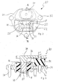
Fig. 1 und2 dargestellte Lager 30 besteht aus einem Gehäuse 24, das mit Befestigungsmitteln 32 an einer Fahrzeugkarosserie, befestigt ist. An dem Gehäuse 24 ist eine Elastomerfeder 22 festgelegt, in die ein Aufnahmeteil 10 für einen Lagerkern 20 einvulkanisiert ist. -
Fig. 3 zeigt, dass in dem Lagerkern 20 Befestigungsöffnungen 21 zur Anbringung einer Getriebestütze 36, vorgesehen sind. Zur weiteren Beeinflussung der dynamischen Eigenschaften des Lagers ist ein Puffer 34 vorgesehen, der mittels der Getriebestütze 36 mit der Elastomerfeder 22 parallel geschaltet ist. - Das Aufnahmeteil 10 ist in den
Fig. 4 und 5 gezeigt. Das Aufnahmeteil 10, das aus Kunststoff besteht, weist eine erste Kernführung 14 und eine zweite Kernführung 16, die durch Stege 12 beabstandet wird, auf. - Die Kernführungen 14, 16 weisen jeweils Führungsschienen 18 auf, die der Anbringung des Lagerkerns 20 dienen, der korrespondierende Führungsnuten 19 aufweist.
- Die Stege 12 verbinden die Kernführungen 14, 16 im Bereich der Führungsschienen 18. Durch die Länge der Stege 12 wird der Abstand der Kernführungen 14, 16 voneinander festgelegt.
- Um die Stege 12 einfacher entfernen zu können sind an den Übergangsstellen zu den Kernführungen 14, 16 Einschnürungen 13 in der Art von Sollbruchstellen vorgesehen.
- Wird der Lagerkern 20 eingesetzt, so wird zunächst die Aufnahmeöffnung 15 (siehe
Fig. 4 und 5 ) mit einem Werkzeug (nicht gezeigt) aufgeweitet. Dabei reißen die Stege 12 bevorzugt an den Einschnürungen 13 auf einer Seite ab. - Alternativ können die Stege 12 mit einem Abscherwerkzeug (nicht gezeigt) entfernt werden, bevor der Lagerkern 20 eingesetzt wird. Ebenso ist es möglich, die Stege 12 durch das Einsetzen des Lagerkerns 20 zu entfernen.
- An den Kernführungen 14, 16 sind Führungsschienen 18 vorgesehen, die in Führungsnuten 19 des Lagerkerns 20 eingreifen und damit festlegen. Weiter sind Einführschrägen 17 an den Kernführungen 14, 16 vorgesehen, die das Einführen des Lagerkerns 20 zwischen den Kernführungen 14, 16 erleichtern.
- Durch das Einführen des Lagerkerns 20 zwischen den Kernführungen 14, 16 werden die Kernführungen 14, 16 des Aufnahmeteils 10 auseinandergeführt, wodurch die Elastomerfeder 22 vorgespannt wird. Dabei ist der Grad der Vorspannung von der Breite des einzusetzenden Lagerkerns 20 abhängig.
- Wird der Lagerkern 20 breiter gewählt, so erhöht sich die Vorspannung der Elastomerfeder 22. Ist andererseits die Breite des Lagerkerns 20 geringer, so ist die Vorspannung der Elastomerfeder 22 reduziert.
- Weiterhin sind in einer bevorzugten Ausführungsform Wölbungen der Elastomerfeder 22 als Begrenzungsanschläge 23 vorgesehen, die eine übermäßige Auslenkung des Lagerkerns 20 in Richtung seiner Kurzseiten und damit eine Zerstörung der Elastomerfeder 22 verhindern.
- Zur erfindungsgemäßen Herstellung des Lagers wird das Gehäuse 24 und das Aufnahmeteil 10 in die Vulkanisationsform eingelegt. Nachfolgend wird der Elastomerkörper eingespritzt und ausvulkanisiert. Nach der Entnahme aus der Vulkanisationsform wird die Aufnahmeöffnung 15 aufgeweitet. Dadurch reißen die Stege 12 einseitig ab. Die Stege 12 werden dann durch ein Abscherwerkzeug entfernt. Danach wird der Lagerkern 20 zwischen die Kernführungen 14, 16 eingesetzt.
- Das hier beschriebene Verfahren zur Herstellung des Lagers erlaubt es vorteilhaft, durch einfache und kostengünstig durchzuführende Produktionsschritte die dynamischen Eigenschaften, insbesondere die Schwingungsisolation des Lagers, einzustellen. Anstatt für jede Einbausituation eine neue Form der Elastomerfeder 22 konstruieren zu müssen, was aufgrund des damit ebenfalls zu ändernden Vulkanisationswerkzeugs sehr kostenintensiv ist, muss nur die Breite des Lagerkerns 20 angepasst werden. Dies ist mit bekannten Verfahren der Metallbearbeitung vergleichsweise einfach durchzuführen.
-
- 10
- Aufnahmeteil
- 12
- Steg
- 13
- Einschnürung
- 14
- Erste Kernführung
- 15
- Aufnahmeöffnung
- 16
- Zweite Kernführung
- 17
- Einführschräge
- 18
- Führungsschiene
- 19
- Führungsnut
- 20
- Lagerkern
- 21
- Befestigungsöffnung
- 22
- Elastomerfeder
- 23
- Begrenzungsanschlag
- 24
- Gehäuse
- 30
- Getriebelager
- 32
- Befestigungsmittel
- 34
- Puffer
- 36
- Getriebestütze
Claims (5)
- Verfahren zum Kalibrieren einer Elastomerfeder (22) eines Lagers, insbesondere eines Getriebelagers (30) eines Kraftfahrzeugs, wobei das Lager ein Gehäuse (24) und einen Lagerkern (20) aufweist, wobei die Elastomerfeder (22) den Lagerkern (20) am Gehäuse (24) abstützt, wobei ein Aufnahmeteil (10) in die Elastomerfeder (22) einvulkanisiert wird, das eine Aufnahmeöffnung (15) für den Lagerkern (20) aufweist und wobei beim Einführen des Lagerkerns (20) eine Vorspannung auf die Elastomerfeder (22) aufgebracht wird, wobei das Aufnahmeteil (10) zumindest eine erste Kernführung (14) und eine zweite Kernführung (16) aufweist, zwischen denen der Lagerkern (20) gehalten wird, dadurch gekennzeichnet, dass das Aufnahmeteil (10) einen Steg (12) aufweist, der die Kernführungen (14, 16) in einem ersten Zustand miteinander verbindet und der vor oder bei dem Einsetzen des Lagerkerns (20) entfernt wird.
- Verfahren nach Anspruch 1, dadurch gekennzeichnet, dass die erste Kernführung (14) und die zweite Kernführung (16) des Aufnahmeteils (10) einander gegenüberliegend angeordnet sind und dass der Lagerkern (20) zwischen den Kernführungen (14, 16) eingesetzt wird.
- Verfahren nach Anspruch 2, dadurch gekennzeichnet, dass die Aufnahmeöffnung (15) zwischen der ersten Kernführung (14) und der zweiten Kernführung (16) zunächst aufgeweitet wird und dann der Steg (12) entfernt wird.
- Verfahren nach einem Ansprüche 2 oder 3, dadurch gekennzeichnet, dass die Länge des Stegs (12) den Abstand der ersten Kernführung (14) von der zweiten Kernführung (16) festlegt.
- Verfahren nach einem der voranstehenden Ansprüche, dadurch gekennzeichnet, dass abhängig von der gewünschten Vorspannung der Elastomerfeder (22) die Maße des einzusetzenden Lagerkerns (20) verändert werden.
Applications Claiming Priority (2)
| Application Number | Priority Date | Filing Date | Title |
|---|---|---|---|
| DE102006047993 | 2006-10-10 | ||
| PCT/EP2007/060486 WO2008043695A1 (de) | 2006-10-10 | 2007-10-02 | Verfahren zum kalibrieren einer elastomerfeder eines lagers sowie nach diesem verfahren hergestelltes lager |
Publications (2)
| Publication Number | Publication Date |
|---|---|
| EP2076688A1 EP2076688A1 (de) | 2009-07-08 |
| EP2076688B1 true EP2076688B1 (de) | 2012-01-25 |
Family
ID=38720169
Family Applications (1)
| Application Number | Title | Priority Date | Filing Date |
|---|---|---|---|
| EP07820866A Not-in-force EP2076688B1 (de) | 2006-10-10 | 2007-10-02 | Verfahren zum kalibrieren einer elastomerfeder eines lagers |
Country Status (6)
| Country | Link |
|---|---|
| US (1) | US8262067B2 (de) |
| EP (1) | EP2076688B1 (de) |
| CN (1) | CN101501360B (de) |
| AT (1) | ATE543025T1 (de) |
| ES (1) | ES2381646T3 (de) |
| WO (1) | WO2008043695A1 (de) |
Families Citing this family (4)
| Publication number | Priority date | Publication date | Assignee | Title |
|---|---|---|---|---|
| US8579510B2 (en) * | 2010-03-12 | 2013-11-12 | Hendrickson Usa, L.L.C. | Rotatable bar pin bushing assembly |
| KR101542796B1 (ko) | 2014-04-16 | 2015-08-10 | (주)디티알 | 차량용 마운트 및 그 제조방법 |
| DE102017211700A1 (de) * | 2017-07-07 | 2019-01-10 | Bayerische Motoren Werke Aktiengesellschaft | Motor- oder Getriebelager für ein Kraftfahrzeug |
| JP7536707B2 (ja) * | 2021-05-11 | 2024-08-20 | 株式会社プロスパイラ | 防振装置 |
Family Cites Families (11)
| Publication number | Priority date | Publication date | Assignee | Title |
|---|---|---|---|---|
| DE3905686C1 (de) | 1989-02-24 | 1990-06-07 | Fa. Carl Freudenberg, 6940 Weinheim, De | |
| JPH04266644A (ja) * | 1991-02-19 | 1992-09-22 | Bridgestone Corp | 防振装置 |
| US5645075A (en) | 1992-02-18 | 1997-07-08 | Symbiosis Corporation | Jaw assembly for an endoscopic instrument |
| FR2730537B1 (fr) * | 1995-02-13 | 1997-04-25 | Hutchinson | Manchon antivibratoire hydraulique et son procede de fabrication |
| JP4025410B2 (ja) * | 1998-02-19 | 2007-12-19 | 東海ゴム工業株式会社 | 防振装置の製造方法 |
| JP2001280420A (ja) * | 2000-03-30 | 2001-10-10 | Tokai Rubber Ind Ltd | 筒型ダイナミックダンパおよびその製造方法 |
| DE60131978T2 (de) * | 2000-08-04 | 2008-12-04 | Honda Giken Kogyo K.K. | Elastische buchse und methode zu druckseinbringen einer elastischen buchse |
| JP3770170B2 (ja) * | 2001-12-10 | 2006-04-26 | 東海ゴム工業株式会社 | 防振ブッシュ |
| CA2520739A1 (en) * | 2003-06-10 | 2005-01-06 | Cooper-Standard Automotive Inc. | A vibration isolator assembly having altered stress characteristics and method of altering stress characteristics of same |
| US7204479B2 (en) * | 2003-06-10 | 2007-04-17 | Cooper-Standard Automotive Inc. | Vibration isolator assembly having altered stress characteristics, and method of altering stress characteristics of same |
| US20060061023A1 (en) * | 2004-09-17 | 2006-03-23 | Cooper Technology Services, Llc | Dual window preloaded engine bushing |
-
2007
- 2007-10-02 WO PCT/EP2007/060486 patent/WO2008043695A1/de not_active Ceased
- 2007-10-02 ES ES07820866T patent/ES2381646T3/es active Active
- 2007-10-02 CN CN200780029398.XA patent/CN101501360B/zh not_active Expired - Fee Related
- 2007-10-02 AT AT07820866T patent/ATE543025T1/de active
- 2007-10-02 EP EP07820866A patent/EP2076688B1/de not_active Not-in-force
-
2009
- 2009-02-20 US US12/389,406 patent/US8262067B2/en active Active
Also Published As
| Publication number | Publication date |
|---|---|
| ES2381646T3 (es) | 2012-05-30 |
| EP2076688A1 (de) | 2009-07-08 |
| CN101501360A (zh) | 2009-08-05 |
| WO2008043695A1 (de) | 2008-04-17 |
| ATE543025T1 (de) | 2012-02-15 |
| CN101501360B (zh) | 2011-03-23 |
| US20090152780A1 (en) | 2009-06-18 |
| US8262067B2 (en) | 2012-09-11 |
Similar Documents
| Publication | Publication Date | Title |
|---|---|---|
| DE102005043234B4 (de) | Verfahren zur Herstellung eines elastomeren Buchsenlagers | |
| DE4025284C2 (de) | ||
| DE7737712U1 (de) | Vorspannbares Lagerelement | |
| DE102012024653A1 (de) | Entkopplungselement | |
| EP3006765A1 (de) | Elastomerlager als buchsenlager | |
| EP1287273A1 (de) | Hydraulisch dämpfendes buchsenlager | |
| EP1409887A1 (de) | Gummilager mit versteifungselement | |
| EP3586028B1 (de) | Elastisches lager | |
| DE102019134083A1 (de) | Zahnrad | |
| DE102005003945B4 (de) | Buchsenlager mit in Umfangsrichtung wechselnder radialer Steifigkeit | |
| WO2008043695A1 (de) | Verfahren zum kalibrieren einer elastomerfeder eines lagers sowie nach diesem verfahren hergestelltes lager | |
| DE102018121219B4 (de) | Lagerbuchse für ein Sackloch und Lenkgetriebeaufhängung für ein Fahrzeug | |
| EP1181465B1 (de) | Gummilager mit abgestuftem dämpfungsverhalten | |
| EP3110680B1 (de) | Lenkwelle für ein kraftfahrzeug | |
| DE102006055127B4 (de) | Verfahren zum Kalibrieren einer Elastomerfeder eines Lagers sowie nach diesem Verfahren hergestelltes Lager | |
| DE102012017319A1 (de) | Befestigungsanordnung zwischen einem Radiallager und einem Stützarm sowie Fahrzeug mit einer derartigen Befestigungsanordnung | |
| EP1479930B1 (de) | Lageraufnahme und Verfahren zum Herstellen einer Lageraufnahme | |
| EP1908987A2 (de) | Elastische Lagerbuchse mit hydraulischer Dämpfung | |
| DE102006050070B4 (de) | Elastisches Lager für ein Kraftfahrzeugaggregat, Verfahren zur Herstellung eines elastischen Lagers, Anordnung zum Einstellen der Lagerungscharakteristik eines elastischen Lagers | |
| DE102005035478B4 (de) | Verfahren und Werkzeug zur Herstellung eines Flansches an einem Buchsenlager | |
| DE102004054618A1 (de) | Verfahren zur Herstellung eines elastomeren Lagers, danach hergestelltes Buchsenlager und Vorrichtung zur Herstellung | |
| EP2990689A1 (de) | Riemenscheibe sowie riementrieb mit derartiger riemenscheibe | |
| DE19910308B4 (de) | Hydraulisch dämpfendes Gummilager mit Axialanschlägen sowie ein Verfahren zur Herstellung eines solchen hydraulisch dämpfenden Gummilagers mit integrierten Axialanschlägen | |
| DE102018220654A1 (de) | Dämpfventilanordnung, insbesondere für einen Schwingungsdämpfer | |
| DE102015211365A1 (de) | Gleitschiene mit hydrostatischer Lagerung |
Legal Events
| Date | Code | Title | Description |
|---|---|---|---|
| PUAI | Public reference made under article 153(3) epc to a published international application that has entered the european phase |
Free format text: ORIGINAL CODE: 0009012 |
|
| 17P | Request for examination filed |
Effective date: 20080722 |
|
| AK | Designated contracting states |
Kind code of ref document: A1 Designated state(s): AT BE BG CH CY CZ DE DK EE ES FI FR GB GR HU IE IS IT LI LT LU LV MC MT NL PL PT RO SE SI SK TR |
|
| RAP1 | Party data changed (applicant data changed or rights of an application transferred) |
Owner name: TRELLEBORG AUTOMOTIVE GERMANY GMBH |
|
| 17Q | First examination report despatched |
Effective date: 20110121 |
|
| GRAP | Despatch of communication of intention to grant a patent |
Free format text: ORIGINAL CODE: EPIDOSNIGR1 |
|
| RTI1 | Title (correction) |
Free format text: METHOD FOR CALIBRATING AN ELASTOMER SPRING OF A MOUNT |
|
| RAP1 | Party data changed (applicant data changed or rights of an application transferred) |
Owner name: TRELLEBORG AUTOMOTIVE GERMANY GMBH |
|
| DAX | Request for extension of the european patent (deleted) | ||
| GRAS | Grant fee paid |
Free format text: ORIGINAL CODE: EPIDOSNIGR3 |
|
| GRAA | (expected) grant |
Free format text: ORIGINAL CODE: 0009210 |
|
| AK | Designated contracting states |
Kind code of ref document: B1 Designated state(s): AT BE BG CH CY CZ DE DK EE ES FI FR GB GR HU IE IS IT LI LT LU LV MC MT NL PL PT RO SE SI SK TR |
|
| REG | Reference to a national code |
Ref country code: GB Ref legal event code: FG4D Free format text: NOT ENGLISH |
|
| REG | Reference to a national code |
Ref country code: CH Ref legal event code: EP |
|
| REG | Reference to a national code |
Ref country code: AT Ref legal event code: REF Ref document number: 543025 Country of ref document: AT Kind code of ref document: T Effective date: 20120215 |
|
| REG | Reference to a national code |
Ref country code: IE Ref legal event code: FG4D |
|
| REG | Reference to a national code |
Ref country code: DE Ref legal event code: R096 Ref document number: 502007009175 Country of ref document: DE Effective date: 20120322 |
|
| REG | Reference to a national code |
Ref country code: RO Ref legal event code: EPE |
|
| REG | Reference to a national code |
Ref country code: NL Ref legal event code: VDEP Effective date: 20120125 |
|
| REG | Reference to a national code |
Ref country code: ES Ref legal event code: FG2A Ref document number: 2381646 Country of ref document: ES Kind code of ref document: T3 Effective date: 20120530 |
|
| LTIE | Lt: invalidation of european patent or patent extension |
Effective date: 20120125 |
|
| PG25 | Lapsed in a contracting state [announced via postgrant information from national office to epo] |
Ref country code: NL Free format text: LAPSE BECAUSE OF FAILURE TO SUBMIT A TRANSLATION OF THE DESCRIPTION OR TO PAY THE FEE WITHIN THE PRESCRIBED TIME-LIMIT Effective date: 20120125 Ref country code: BG Free format text: LAPSE BECAUSE OF FAILURE TO SUBMIT A TRANSLATION OF THE DESCRIPTION OR TO PAY THE FEE WITHIN THE PRESCRIBED TIME-LIMIT Effective date: 20120425 Ref country code: IS Free format text: LAPSE BECAUSE OF FAILURE TO SUBMIT A TRANSLATION OF THE DESCRIPTION OR TO PAY THE FEE WITHIN THE PRESCRIBED TIME-LIMIT Effective date: 20120525 Ref country code: LT Free format text: LAPSE BECAUSE OF FAILURE TO SUBMIT A TRANSLATION OF THE DESCRIPTION OR TO PAY THE FEE WITHIN THE PRESCRIBED TIME-LIMIT Effective date: 20120125 |
|
| REG | Reference to a national code |
Ref country code: IE Ref legal event code: FD4D |
|
| PG25 | Lapsed in a contracting state [announced via postgrant information from national office to epo] |
Ref country code: LV Free format text: LAPSE BECAUSE OF FAILURE TO SUBMIT A TRANSLATION OF THE DESCRIPTION OR TO PAY THE FEE WITHIN THE PRESCRIBED TIME-LIMIT Effective date: 20120125 Ref country code: PL Free format text: LAPSE BECAUSE OF FAILURE TO SUBMIT A TRANSLATION OF THE DESCRIPTION OR TO PAY THE FEE WITHIN THE PRESCRIBED TIME-LIMIT Effective date: 20120125 Ref country code: GR Free format text: LAPSE BECAUSE OF FAILURE TO SUBMIT A TRANSLATION OF THE DESCRIPTION OR TO PAY THE FEE WITHIN THE PRESCRIBED TIME-LIMIT Effective date: 20120426 Ref country code: PT Free format text: LAPSE BECAUSE OF FAILURE TO SUBMIT A TRANSLATION OF THE DESCRIPTION OR TO PAY THE FEE WITHIN THE PRESCRIBED TIME-LIMIT Effective date: 20120525 Ref country code: FI Free format text: LAPSE BECAUSE OF FAILURE TO SUBMIT A TRANSLATION OF THE DESCRIPTION OR TO PAY THE FEE WITHIN THE PRESCRIBED TIME-LIMIT Effective date: 20120125 |
|
| PG25 | Lapsed in a contracting state [announced via postgrant information from national office to epo] |
Ref country code: CY Free format text: LAPSE BECAUSE OF FAILURE TO SUBMIT A TRANSLATION OF THE DESCRIPTION OR TO PAY THE FEE WITHIN THE PRESCRIBED TIME-LIMIT Effective date: 20120125 |
|
| PG25 | Lapsed in a contracting state [announced via postgrant information from national office to epo] |
Ref country code: EE Free format text: LAPSE BECAUSE OF FAILURE TO SUBMIT A TRANSLATION OF THE DESCRIPTION OR TO PAY THE FEE WITHIN THE PRESCRIBED TIME-LIMIT Effective date: 20120125 Ref country code: SI Free format text: LAPSE BECAUSE OF FAILURE TO SUBMIT A TRANSLATION OF THE DESCRIPTION OR TO PAY THE FEE WITHIN THE PRESCRIBED TIME-LIMIT Effective date: 20120125 Ref country code: CZ Free format text: LAPSE BECAUSE OF FAILURE TO SUBMIT A TRANSLATION OF THE DESCRIPTION OR TO PAY THE FEE WITHIN THE PRESCRIBED TIME-LIMIT Effective date: 20120125 Ref country code: IE Free format text: LAPSE BECAUSE OF FAILURE TO SUBMIT A TRANSLATION OF THE DESCRIPTION OR TO PAY THE FEE WITHIN THE PRESCRIBED TIME-LIMIT Effective date: 20120125 Ref country code: DK Free format text: LAPSE BECAUSE OF FAILURE TO SUBMIT A TRANSLATION OF THE DESCRIPTION OR TO PAY THE FEE WITHIN THE PRESCRIBED TIME-LIMIT Effective date: 20120125 Ref country code: SE Free format text: LAPSE BECAUSE OF FAILURE TO SUBMIT A TRANSLATION OF THE DESCRIPTION OR TO PAY THE FEE WITHIN THE PRESCRIBED TIME-LIMIT Effective date: 20120125 |
|
| PG25 | Lapsed in a contracting state [announced via postgrant information from national office to epo] |
Ref country code: SK Free format text: LAPSE BECAUSE OF FAILURE TO SUBMIT A TRANSLATION OF THE DESCRIPTION OR TO PAY THE FEE WITHIN THE PRESCRIBED TIME-LIMIT Effective date: 20120125 Ref country code: IT Free format text: LAPSE BECAUSE OF FAILURE TO SUBMIT A TRANSLATION OF THE DESCRIPTION OR TO PAY THE FEE WITHIN THE PRESCRIBED TIME-LIMIT Effective date: 20120125 |
|
| PLBE | No opposition filed within time limit |
Free format text: ORIGINAL CODE: 0009261 |
|
| STAA | Information on the status of an ep patent application or granted ep patent |
Free format text: STATUS: NO OPPOSITION FILED WITHIN TIME LIMIT |
|
| 26N | No opposition filed |
Effective date: 20121026 |
|
| REG | Reference to a national code |
Ref country code: DE Ref legal event code: R097 Ref document number: 502007009175 Country of ref document: DE Effective date: 20121026 |
|
| BERE | Be: lapsed |
Owner name: TRELLEBORG AUTOMOTIVE GERMANY G.M.B.H. Effective date: 20121031 |
|
| PG25 | Lapsed in a contracting state [announced via postgrant information from national office to epo] |
Ref country code: MC Free format text: LAPSE BECAUSE OF NON-PAYMENT OF DUE FEES Effective date: 20121031 |
|
| REG | Reference to a national code |
Ref country code: CH Ref legal event code: PL |
|
| GBPC | Gb: european patent ceased through non-payment of renewal fee |
Effective date: 20121002 |
|
| PG25 | Lapsed in a contracting state [announced via postgrant information from national office to epo] |
Ref country code: LI Free format text: LAPSE BECAUSE OF NON-PAYMENT OF DUE FEES Effective date: 20121031 Ref country code: CH Free format text: LAPSE BECAUSE OF NON-PAYMENT OF DUE FEES Effective date: 20121031 Ref country code: GB Free format text: LAPSE BECAUSE OF NON-PAYMENT OF DUE FEES Effective date: 20121002 Ref country code: BE Free format text: LAPSE BECAUSE OF NON-PAYMENT OF DUE FEES Effective date: 20121031 |
|
| PG25 | Lapsed in a contracting state [announced via postgrant information from national office to epo] |
Ref country code: MT Free format text: LAPSE BECAUSE OF FAILURE TO SUBMIT A TRANSLATION OF THE DESCRIPTION OR TO PAY THE FEE WITHIN THE PRESCRIBED TIME-LIMIT Effective date: 20120125 |
|
| REG | Reference to a national code |
Ref country code: AT Ref legal event code: MM01 Ref document number: 543025 Country of ref document: AT Kind code of ref document: T Effective date: 20121031 |
|
| PG25 | Lapsed in a contracting state [announced via postgrant information from national office to epo] |
Ref country code: AT Free format text: LAPSE BECAUSE OF NON-PAYMENT OF DUE FEES Effective date: 20121031 |
|
| PG25 | Lapsed in a contracting state [announced via postgrant information from national office to epo] |
Ref country code: LU Free format text: LAPSE BECAUSE OF NON-PAYMENT OF DUE FEES Effective date: 20121002 |
|
| PG25 | Lapsed in a contracting state [announced via postgrant information from national office to epo] |
Ref country code: HU Free format text: LAPSE BECAUSE OF FAILURE TO SUBMIT A TRANSLATION OF THE DESCRIPTION OR TO PAY THE FEE WITHIN THE PRESCRIBED TIME-LIMIT Effective date: 20071002 |
|
| REG | Reference to a national code |
Ref country code: FR Ref legal event code: PLFP Year of fee payment: 9 |
|
| REG | Reference to a national code |
Ref country code: FR Ref legal event code: PLFP Year of fee payment: 10 |
|
| REG | Reference to a national code |
Ref country code: FR Ref legal event code: PLFP Year of fee payment: 11 |
|
| PGFP | Annual fee paid to national office [announced via postgrant information from national office to epo] |
Ref country code: TR Payment date: 20170921 Year of fee payment: 11 |
|
| REG | Reference to a national code |
Ref country code: FR Ref legal event code: PLFP Year of fee payment: 12 |
|
| PGFP | Annual fee paid to national office [announced via postgrant information from national office to epo] |
Ref country code: RO Payment date: 20180925 Year of fee payment: 12 |
|
| REG | Reference to a national code |
Ref country code: DE Ref legal event code: R082 Ref document number: 502007009175 Country of ref document: DE Representative=s name: PATENTANWAELTE OLBRICHT, BUCHHOLD, KEULERTZ PA, DE |
|
| PG25 | Lapsed in a contracting state [announced via postgrant information from national office to epo] |
Ref country code: RO Free format text: LAPSE BECAUSE OF NON-PAYMENT OF DUE FEES Effective date: 20191002 |
|
| PG25 | Lapsed in a contracting state [announced via postgrant information from national office to epo] |
Ref country code: TR Free format text: LAPSE BECAUSE OF NON-PAYMENT OF DUE FEES Effective date: 20191002 |
|
| PGFP | Annual fee paid to national office [announced via postgrant information from national office to epo] |
Ref country code: FR Payment date: 20221028 Year of fee payment: 16 |
|
| PGFP | Annual fee paid to national office [announced via postgrant information from national office to epo] |
Ref country code: ES Payment date: 20221222 Year of fee payment: 16 Ref country code: DE Payment date: 20221031 Year of fee payment: 16 |
|
| REG | Reference to a national code |
Ref country code: DE Ref legal event code: R119 Ref document number: 502007009175 Country of ref document: DE |
|
| PG25 | Lapsed in a contracting state [announced via postgrant information from national office to epo] |
Ref country code: FR Free format text: LAPSE BECAUSE OF NON-PAYMENT OF DUE FEES Effective date: 20231031 Ref country code: DE Free format text: LAPSE BECAUSE OF NON-PAYMENT OF DUE FEES Effective date: 20240501 |
|
| REG | Reference to a national code |
Ref country code: ES Ref legal event code: FD2A Effective date: 20241126 |
|
| PG25 | Lapsed in a contracting state [announced via postgrant information from national office to epo] |
Ref country code: ES Free format text: LAPSE BECAUSE OF NON-PAYMENT OF DUE FEES Effective date: 20231003 |
|
| PG25 | Lapsed in a contracting state [announced via postgrant information from national office to epo] |
Ref country code: ES Free format text: LAPSE BECAUSE OF NON-PAYMENT OF DUE FEES Effective date: 20231003 |