EP2075614B1 - Zoom lens system - Google Patents
Zoom lens system Download PDFInfo
- Publication number
- EP2075614B1 EP2075614B1 EP08171775.3A EP08171775A EP2075614B1 EP 2075614 B1 EP2075614 B1 EP 2075614B1 EP 08171775 A EP08171775 A EP 08171775A EP 2075614 B1 EP2075614 B1 EP 2075614B1
- Authority
- EP
- European Patent Office
- Prior art keywords
- lens
- lens group
- zoom lens
- lens system
- denotes
- Prior art date
- Legal status (The legal status is an assumption and is not a legal conclusion. Google has not performed a legal analysis and makes no representation as to the accuracy of the status listed.)
- Expired - Fee Related
Links
Images


Classifications
-
- G—PHYSICS
- G02—OPTICS
- G02B—OPTICAL ELEMENTS, SYSTEMS OR APPARATUS
- G02B15/00—Optical objectives with means for varying the magnification
- G02B15/14—Optical objectives with means for varying the magnification by axial movement of one or more lenses or groups of lenses relative to the image plane for continuously varying the equivalent focal length of the objective
- G02B15/143—Optical objectives with means for varying the magnification by axial movement of one or more lenses or groups of lenses relative to the image plane for continuously varying the equivalent focal length of the objective having three groups only
- G02B15/1435—Optical objectives with means for varying the magnification by axial movement of one or more lenses or groups of lenses relative to the image plane for continuously varying the equivalent focal length of the objective having three groups only the first group being negative
- G02B15/143507—Optical objectives with means for varying the magnification by axial movement of one or more lenses or groups of lenses relative to the image plane for continuously varying the equivalent focal length of the objective having three groups only the first group being negative arranged -++
Definitions
- the present invention relates to a zoom lens system and an optical device equipped with the zoom lens.
- imaging apparatus such as digital still cameras and digital video cameras using solid-state imaging devices have rapidly been attaining higher performances and more compact sizes.
- these imaging apparatus employ zoom lens systems as their imaging lenses.
- the zoom lens systems allow photographers to easily take a picture with an optimal angle of view for a shooting condition.
- there have currently been strong demands for these zoom lens systems to achieve wider angle and higher variable power only very few examples of zoom lens systems have been proposed which enable sufficiently telephoto shooting while having an angle of view of 70 to 80 degrees or greater in the wide-angle end state.
- Known as an example achieving wider angle and higher variable power ratio at the same time is the lens system of Example 2 in Japanese Patent Application Laid-Open No. 2006-084829 .
- the conventional zoom lens systems have a problem that aberrations may not fully be corrected in the wide-angle end state, thus failing to achieve favorable imaging performances.
- the zoom lens system in accordance with the present invention comprises, in order from an object along an optical axis, a first lens group having a negative refractive power, a second lens group having a positive refractive power, and a third lens group having a positive refractive power.
- the zoom lens system is constructed such as to satisfy the following conditional expression: 0.6 ⁇ Ymax ⁇ ft / f 1 2 ⁇ 1.0 where Ymax denotes the maximum image height of the zoom lens system, ft denotes a focal length of the zoom lens system in a telephoto end state, and fl denotes a focal length of the first lens group.
- the zoom lens system satisfies the following conditional expression: 0.51 ⁇ N 2 nav ⁇ 0.8 ft ⁇ tan ⁇ w / TLw ⁇ 0.95
- N2nav denotes an average refractive index value of materials of all the negative lenses included in the second lens group at d-line
- ⁇ w denotes a half angle of view of the zoom lens system in a wide-angle end state
- TLw denotes a total length of the zoom lens system in the wide-angle end state
- ft denotes the focal length of the zoom lens system in the telephoto end state.
- the zoom lens system satisfies the following conditional expression: 0.3 ⁇ ft ⁇ L 12 t / f 1 ⁇ 2.0
- L12t denotes a distance along the optical axis between the lens surface closest to an image in the first lens group and the lens surface closest to the object in the second lens group in the telephoto end state
- ft denotes the focal length of the zoom lens system in the telephoto end state
- fl denotes the focal length of the first lens group.
- the zoom lens system satisfies the following conditional expression: 0.36 ⁇ Nn ⁇ Np ⁇ 0.80 where Nn denotes the highest refractive index of materials of negative lenses included in the second lens group at d-line, and Np denotes the lowest refractive index of materials of positive lenses included in the second lens group at d-line.
- the zoom lens system satisfies the following conditional expression: 3.0 ⁇ Nn + 0.05 ⁇ ⁇ n
- Nn denotes the highest refractive index of materials of negative lenses included in the second lens group at d-line
- vn denotes Abbe number of a material of a lens having the highest refractive index in materials of negative lenses included in the second lens group at d-line.
- the second lens group has an F-number determining member and at least one positive lens positioned on the object side of the F-number determining member.
- the second lens group in the zoom lens system has, in order from the object along the optical axis, two positive lenses and one negative lens.
- the first lens group in the zoom lens system has, in order from the object along the optical axis, at least one negative meniscus lens and one positive lens.
- the negative meniscus lens constituting the first lens group is arranged closest to the object in the first lens group.
- At least the image-side lens surface in lens surfaces of the negative meniscus lens constituting the first lens group is formed aspherical.
- At least the first and second lens groups move so as to decrease a distance between the first lens group and the second lens group and increase a distance between the second lens group and the third lens group.
- the optical device in accordance with the present invention is constructed such as to include any of the zoom lens systems mentioned above.
- the present invention can provide a compact zoom lens system, suitable for solid-state imaging devices, having excellent performances while achieving a wide angle and a high variable power ratio, and an optical device equipped with the zoom lens system.
- This zoom lens system ZL is a zoom lens system of negative preceding type comprising, in order from an object along an optical axis, a first lens group G1 having a negative refractive power as a whole, a second lens group G2 having a positive refractive power as a whole, and a third lens group G3 having a positive refractive power as a whole.
- the second lens group G2 acts as a variable power part and master lens group
- the first lens group G1 acts as a compensator group.
- the third lens group G3 is constructed such as to optimize the exit pupil position of the whole zoom lens system ZL with respect to an imaging device (depicted as an image surface I in Figs. 1A to 1C ) and correct the aberrations left after the correction by the first and second lens groups G1, G2.
- the zoom lens system ZL corresponds to Example 1 which will be explained later.
- Ymax be the maximum image height of the zoom lens system
- ft be a focal length of the zoom lens system in a telephoto end state
- fl be a focal length of the first lens group
- the conditional expression (1) defines an appropriate range for the maximum image height of the zoom lens system ZL, its focal length in the telephoto end state, and the focal length of the first lens group G 1.
- the first lens group G1 acts to initially form an image of an object, while the position and size of the image is determined by the focal length f1 of the first lens group G1.
- Its subsequent lens group variably magnifies the image formed by the first lens group G1, so as to form an image having a finally desirable size onto an imaging device surface (image surface I). Therefore, for determining the whole structure of the zoom lens system ZL, it is very important to appropriately set the focal length f1 of the first lens group G1.
- the focal length fl of the first lens group G1 is inappropriate, it becomes very hard to attain desirable variable power ratio, total size of the zoom lens system ZL, aberration correction state, and the like.
- the present invention can exhibit its effects more favorably.
- the lower limit of the conditional expression (1) is 0.63 and/or its upper limit is 0.9, the present invention can exhibit its effects at a maximum.
- N2nav be an average refractive index value of materials of all the negative lenses included in the second lens group G2 at d-line
- ⁇ w be a half angle of view of the zoom lens system in a wide-angle end state
- TLw be a total length of the zoom lens system in the wide-angle end state
- ft be the focal length of the zoom lens system in the telephoto end state
- the conditional expression (2) is a condition for favorably correcting the curvature of a sagittal image surface that becomes problematic in particular when attaining a wider angle and a smaller size in the zoom lens system ZL.
- the curvature of the sagittal image surface becomes greater as the half angle of view ⁇ w increases. This tendency becomes more remarkable as the zoom lens system ZL is made smaller.
- negative lenses also perform important actions in terms of aberration correction, e.g., reduce the Petzval sum to an appropriate value.
- the conditional expression (2) defines an appropriate range with respect to the refractive index of negative lenses having such roles contradictory to each other.
- the present invention can exhibit its effects more favorably.
- the lower limit of the conditional expression (2) is 0.51 and/or its upper limit is 0.85, the present invention can exhibit its effects at a maximum.
- the average value N2nav of refractive index of materials of all the negative lenses included in the second lens group G2 at d-line is greater than 1.90.
- L12t be the distance along the optical axis between the lens surface (e.g., surface No. 6 in Figs. 1A to 1C ) closest to the image in the first lens group G1 and the lens surface (e.g., surface No. 7 in Figs. 1A to 1C ) closest to the object in the second lens group G2 in the telephoto end state
- ft be the focal length of the zoom lens system in the telephoto end state
- fl be the focal length of the first lens group G1
- the conditional expression (3) defines an appropriate range for the distance between the lens surface closest to the image in the first lens group G1 and the lens surface closest to the object in the second lens group G2 in the telephoto end state.
- is less than the lower limit of the conditional expression (3), it is unfavorable in that the lens surface closest to the image in the first lens group G1 and the lens surface closest to the object in the second lens group G2 may approach each other so as to come into contact with each other in the telephoto end state because of manufacturing errors. It is also unfavorable in that the Petzval sum increases, whereby field curvature and astigmatism are hard to correct at the same time in the intermediate focal length state.
- exceeds the upper limit of the conditional expression (3), on the other hand, it is unfavorable in that upper coma is hard to correct in the intermediate focal length state.
- the present invention can exhibit its effects more favorably.
- the lower limit of the conditional expression (3) is 0.4 and/or its upper limit is 1.8
- the present invention can exhibit its effects at a maximum.
- Nn be the highest refractive index of materials of negative lenses included in the second lens group G2 at d-line
- Np be the lowest refractive index of materials of positive lenses included in the second lens group G2 at d-line
- the conditional expression (4) is a condition for favorably correcting the curvature of the sagittal image surface in the wide-angle end state.
- an optical system improved over that of triplet or telephoto type having a positive refractive power as a whole is often used for the second lens group G2. It is necessary for this kind of optical system to appropriately select materials for negative and positive lenses in order to favorably correct off-axis aberrations in particular, and arrange the negative and positive lenses such that their aberrations cancel each other out.
- the conditional expression (4) defines an optimal range for the material selection.
- Nn - Np is less than the lower limit of the conditional expression (4), it is unfavorable in that the curvature of the sagittal image surface increases in the wide-angle end state, thereby lowering the image quality in marginal parts of pictures.
- Nn - Np exceeds the upper limit of the conditional expression (4), on the other hand, it is unfavorable in that the Petzval sum increases remarkably, so that field curvature and astigmatism are hard to correct at the same time in the telephoto end state.
- the present invention can exhibit its effects more favorably.
- the lower limit of the conditional expression (4) is 0.4 and/or its upper limit is 0.7, the present invention can exhibit its effects at a maximum.
- Nn be the highest refractive index of materials of negative lenses included in the second lens group G2 at d-line
- vn Abbe number of a material of a lens having the highest refractive index in materials of negative lenses included in the second lens group G2 at d-line
- the conditional expression (5) defines an appropriate range for the refractive index and Abbe number of a negative lens constituting the second lens group G2.
- the zoom lens system ZL has a higher variable power ratio, so as to attain a longer focal length in the telephoto end state, axial chromatic aberration is hard to correct in the telephoto end state in particular. Therefore, an appropriate material must be selected in the second lens group G2 in the zoom lens system ZL having such a high variable power ratio shown here..
- Nn + 0.05 ⁇ vn is less than the lower limit of the conditional expression (5), it is unfavorable in that axial chromatic aberration and differences in spherical aberration dependent on wavelength are hard to correct in the telephoto end state.
- the present invention can exhibit its effects more favorably.
- the lower limit of the conditional expression (5) is 3.2, the present invention can exhibit its effects at a maximum.
- the value of the right-hand side in the conditional expression (5) tends to become greater as the refractive index at d-line increases, materials of lenses can be selected within a range in which the zoom lens system ZL does not lose its performances.
- zoom lens system ZL having a wide angle and a high variable power ratio has an F-number determining member S in the second lens group G2 and at least one positive lens positioned on the object side of the F-number determining member.
- the F-number determining member S is a member, such as an aperture stop, for example, which determines the f number by limiting the diameter of a light beam passing through the whole zoom lens system ZL. Therefore, the F-number determining member S is not restricted to the aperture stop, but may be a lens frame which holds the zoom lens system ZL.
- a luminous flux diverged by the first lens group G1 is incident on the second lens group G2 in a zoom lens system of negative preceding type, such as the zoom lens system ZL shown here, in general, it is necessary for the second lens group G2 to use an optical system which is resistant to brightness.
- the power variable ratio of the zoom lens system ZL is enhanced, it is necessary for the second lens group G2 to yield a high telephoto ratio, so as to shift the principal point of the second lens group G2 to the object side, in order to secure a distance along the optical axis between the first lens group G1 and the second lens group G2 in the telephoto end state.
- the second lens group G2 it is necessary for the second lens group G2 to arrange the F-number determining member at such a position as to minimize the fluctuation in off-axis aberration caused by varying power. From such a viewpoint, it will be desirable if the F-number determining member S is arranged as close to the image as possible.
- a positive lens e.g., positive meniscus lens L21 in Figs. 1A to 1C
- Such a structure can suppress the fluctuation in off-axis aberration caused by varying power, while a sufficient telephoto ratio is imparted by the second lens group G2.
- the second lens group G2 has, in order from the object along the optical axis, two positive lenses and one negative lens (e.g., the first positive lens, second positive lens, and one negative lens correspond to the positive meniscus lens L21, positive lens L22, and negative lens L23, respectively, in Figs. 1A to 1C in order from the object).
- Arranging two positive lenses in series in order from the object and placing a negative lens on their image side is nothing but causing the three lenses to achieve a refractive power arrangement of telephoto type.
- the second lens group G2 can favorably correct spherical aberration, and prevent the first and second lens groups G1, G2 from coming into contact with each other in the telephoto end state even when the variable power ratio is further enhanced.
- the second lens group G2 includes one or two negative lenses.
- the first lens group G1 is arranged such as to have, in order from the object along the optical axis, at least one negative meniscus lens and one positive lens.
- the first lens group G1 can favorably correct distortion in the wide-angle end state.
- at least the image-side lens surface (e.g., surface No. 2 in Figs. 1A to 1C ) of the negative meniscus lens has an aspherical form.
- the distortion in the wide-angle end state can be corrected more favorably.
- the zoom lens system ZL having such a wide angle and high variable power
- focusing from an object at infinity to an object at a very close distance can be performed by moving the first lens group G1 or third lens group G3 toward the object.
- the focusing lens groups are employable for autofocusing and suitable for driving a motor (such as ultrasonic motor) for autofocusing.
- moving the first lens group G1 tends to lower the image quality in marginal parts of pictures in close-up shots, moving the third lens group G3 toward the object is more desirable.
- any of its lens surfaces may be a diffractive surface.
- Any lens may be a gradient-index lens (GRIN lens) or plastic lens. Additional lens groups may be provided on the image side of the third lens group G3 (though not depicted in Figs. 1A to 1C ).
- the zoom lens system ZL having a three-group structure
- the following structural conditions and the like are also applicable to other group structures such as those composed of four and five groups.
- additional lens groups may be inserted between the existing lens groups or arranged adjacent thereto on the image side or object side.
- the lens groups refers to parts, separated from each other by an air space which varies at the time of varying power, each having at least one lens.
- the present invention can combine a shake detection system for detecting shakes of the lens system and driving means with the lens system and drive the whole or part of one of the lens groups constituting the lens system as a vibration reduction lens with the driving means such that the vibration reduction lens group is decentered so as to correct image blurs (fluctuations in the image surface position) due to shakes of the lens system detected by the shake detection system, thus shifting the image, thereby correcting the image blurs.
- the second lens group G2 is the vibration reduction lens group.
- the zoom lens system ZL in accordance with this embodiment can function as a so-called vibration reduction optical system.
- the variable power optical system ZL may have aspherical lens surfaces.
- the aspherical surfaces may be any of those made by grinding, glass-molded aspherical surfaces in which glass is formed aspherical with molds, and composite aspherical surfaces in which a resin is formed aspherical on a surface of glass.
- the spherical or planar lens surfaces are favorable in that processing of lenses and adjustment of their assembling are easy, so as to prevent optical performances from deteriorating because of errors in the processing and adjustment of assembling. They are also favorable in that depicting performances deteriorate less even when the image surface is sifted.
- the first lens group G1, second lens group G2, and third lens group G3 of this embodiment are built into a cylindrical lens barrel.
- the lens groups may be built into the lens barrel one by one in their order along the optical axis, or a part or all of the lens groups may be integrally held with a holding member and then assembled with a lens barrel member.
- a lens barrel member Preferably, after the lens groups are built into the lens barrel, whether or not an image of an object is formed in the state where the lens groups are built into the lens barrel is determined.
- the zoom lens system After the zoom lens system is assembled as mentioned above, its various actions are verified.
- the actions include a varying power action in which at least a part of lens groups moves along the optical axis when varying power, a focusing action in which a lens group for focusing from an object at infinity to an object at a close distance moves along the optical axis, and a camera shake correcting action in which at least a part of lenses moves so as to have a component orthogonal to the optical axis.
- At least the first and second lens groups G1, G2 move such as to decrease the distance between the first lens group G1 and the second lens group G2 and increase the distance between the second lens group G2 and the third lens groups G3.
- the various actions can be verified in any order.
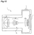
- Figs. 11A, 11B and 12 show the structure of an electronic still camera (hereinafter simply referred to as camera) 1 as an optical device equipped with the above-mentioned zoom lens system ZL.
- camera an electronic still camera
- an undepicted power button is pressed in this camera 1
- an undepicted shutter of its shooting lens system zoom lens system ZL
- the object image formed on the imaging device C is displayed on a liquid crystal monitor 2 arranged behind the camera 1.
- a photographer pushes down a release button, so as to capture the object image with the imaging device C and record it into an undepicted memory for storage.
- an auxiliary light emitting part 4 for emitting auxiliary light when the object is dark
- a wide (W) - telephoto (T) button 5 for zooming the zoom lens system ZL from the wide-angle end state (W) to the telephoto end state (T)
- a function button 6 used for setting various conditions and the like of the camera 1, and the like.
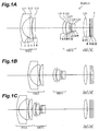
- FIGs. 1A to 1C show the refractive power distribution of the zoom lens system ZL and how its lens groups move when the focal length state changes from the wide-angle end state ( Fig. 1A ) to the telephoto end state ( Fig. 1C ) by way of the intermediate focal length state (Fig. IB). As shown in Figs.
- the depicted zoom lens system ZL has, in order from the object, the first lens group G1 having a negative refractive power as a whole, the second lens group G2 having a positive refractive power as a whole, and the third lens group G3 having a positive refractive power as a whole, and is constructed such that, when varying power from the wide-angle end state to the telephoto end state, the first and second lens groups G1, G2 move so as to decrease the distance between the first lens group G1 and the second lens group G2 and increase the distance between the second lens group G2 and the third lens group G3 in the state where the third lens group G3 is stationary.
- Figs. 1A to 1C show the structure of the zoom lens system ZL1 in accordance with Example 1 of the present invention.
- the first lens group G1 is composed of, in order from the object along the optical axis, a negative meniscus lens L11. having a convex surface facing the object, a double concave negative lens L12, and a positive meniscus lens L13 having a convex surface facing the object, while the image-side lens surface of the negative meniscus lens L11 (surface No. 2) is formed aspherical.
- the second lens group G2 is composed of, in order from the object along the optical axis, a positive meniscus lens L21 having a convex surface facing the object, a cemented lens constructed by cementing a double convex positive lens L22 and a double concave negative lens L23 together, and a cemented lens constructed by cementing a negative meniscus lens L24 having a convex surface facing the object and a double convex positive lens L25 together, while the object-side lens surface of the positive meniscus lens L21 (surface No. 7) is formed aspherical.
- the third lens group G3 is constructed by a double convex positive lens L31 alone.
- the F-number determining member S is arranged on the image side of the vertex on the optical axis of the positive lens L22 in the second lens group G2 and moves together with the second lens group G2 when varying power from the wide-angle end state to the telephoto end state.
- a filter group FL is constructed by a low-pass filter, an infrared cut filter, and the like.
- Table 1 lists values of data in Example 1.
- f, FNO, 2 ⁇ , and Ymax in “Specifications” denote the focal length, F-number, angle of view, and maximum image height, respectively.
- the asterisk on the left side in the first column indicates that the lens surface is an aspherical surface.
- BT refers to back focus.
- y the height perpendicular to the optical axis
- x the distance (sag amount) along the optical axis from the tangent plane at the vertex of the aspherical surface to the aspherical surface at the height y
- R the radius of paraxial curvature (radius of curvature of a reference aspherical surface)
- ⁇ the conical constant
- An the nth-order aspherical coefficient, the aspherical surface is represented by the following expression (a):
- S y y 2 / R / 1 + 1 ⁇ ⁇ y 2 / R 2 1 / 2 + A 4 y 4 + A 6 y 6 + A 8 y 8 + A 10 y 10
- Variable Distance Data lists values of focal lengths and variable distances in the wide-angle end, intermediate focal length, and telephoto end states
- Group Focal Lengths lists the respective focal lengths of the lens groups.
- Values for Conditional Expressions lists values of parameters in the conditional expressions.
- TL, f1, f2, and f3 denote the total length of the zoom lens system ZL, the focal length of the first lens group G1, the focal length of the second lens group G2, and the focal length of the third lens group G3, respectively. The same symbols as those of this example will be used in data of all the following examples.
- mm is generally used for the unit of lengths such as focal length, radius of curvature, and surface distance in the data tables, the unit is not limited thereto, since optical systems can attain similar optical performances even after being proportionally enlarged or reduced.
- the refractive index of air which is 1.000, is omitted in the tables.
- ⁇ denotes a plane.
- E - n (where n is an integer) denotes " ⁇ 10 -n ".
- W, IFL, and T denote the Wide-angle end, Intermediate focal length, and Telephoto end, respectively.
- s, r, d, n, and ⁇ denote the Surface No., Radius of curvature, Surface distance, Refractive index, and Abbe number, respectively, in the following tables.
- the zoom lens system ZL1 in accordance with Example 1 is found to satisfy all the above-mentioned conditional expressions (1) to (5).
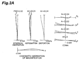
- Figs. 2A to 2C are aberration charts showing various aberrations in the zoom lens system ZL1 in accordance with Example 1 in the infinity in-focus state in the wide-angle end, intermediate focal length, and telephoto end states, respectively.
- FNO and A denote the F-number and the half angle of view, respectively.
- solid and broken lines indicate sagittal and meridional image surfaces, respectively. The same symbols as those of this example will be used in various aberration charts of the following examples.
- the aberration charts show that various aberrations are favorably corrected in each focal length state from the wide-angle end state to the telephoto end state, so that the zoom lens system ZL1 in accordance with Example 1 has excellent optical performances.
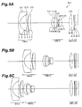
- Figs. 3A to 3C show the structure of the zoom lens system ZL2 in accordance with Example 2 of the present invention.
- the first lens group G1 is composed of, in order from the object along the optical axis, a negative meniscus lens L11 having a convex surface facing the object, a double concave negative lens L12, and a positive meniscus lens L13 having a convex surface facing the object, while the image-side lens surface of the negative meniscus lens L11 (surface No. 2) is formed aspherical.
- the second lens group G2 is composed of, in order from the object along the optical axis, a positive meniscus lens L21 having a convex surface facing the object, a cemented lens constructed by cementing a positive meniscus lens L22 having a convex surface facing the object and a negative meniscus lens L23 having a convex surface facing the object together, and a positive meniscus lens L24 having a convex surface facing the object, while the object-side lens surface of the positive meniscus lens L21 (surface No. 7) and both surfaces of the positive meniscus lens L24 (surface Nos. 13 and 14) are formed aspherical.
- the third lens group G3 is constructed by a double convex positive lens L31 alone.
- the F-number determining member S is arranged on the image side of the vertex on the optical axis of the positive lens L22 in the second lens group G2 and moves together with the second lens group G2 when varying power from the wide-angle end state to the telephoto end state.
- the filter group FL is constructed by a low-pass filter, an infrared cut filter, and the like.
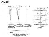
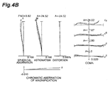
- Figs. 4A to 4C are aberration charts showing various aberrations in the zoom lens system ZL2 in accordance with Example 2 in the infinity in-focus state in the wide-angle end, intermediate focal length, and telephoto end states, respectively.
- the aberration charts show that various aberrations are favorably corrected in each focal length state from the wide-angle end state to the telephoto end state, so that the zoom lens system ZL2 in accordance with Example 2 has excellent optical performances.
- Figs. 5A to 5C show the structure of the zoom lens system ZL3 in accordance with Example 3 of the present invention.
- the first lens group G1 is composed of, in order from the object along the optical axis, a negative meniscus lens L11 having a convex surface facing the object, a double concave negative lens L12, and a positive meniscus lens L13 having a convex surface facing the object, while the image-side lens surface of the negative meniscus lens L11 (surface No. 2) is formed aspherical.
- the second lens group G2 is composed of, in order from the object along the optical axis, a positive meniscus lens L21 having a convex surface facing the object, a cemented lens constructed by cementing a positive meniscus lens L22 having a convex surface facing the object and a negative meniscus lens L23 having a convex surface facing the object together, and a cemented lens constructed by cementing a negative meniscus lens L24 having a convex surface facing the object and a double convex positive lens L25 together, while the object-side lens surface of the positive meniscus lens L21 (surface No. 7) is formed aspherical.
- the third lens group G3 is constructed by a double convex positive lens L31 alone.
- the F-number determining member S is arranged on the image side of the vertex on the optical axis of the positive lens L22 in the second lens group G2 and moves together with the second lens group G2 when varying power from the wide-angle end state to the telephoto end state.
- the filter group FL is constructed by a low-pass filter, an infrared cut filter, and the like.
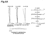
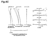
- Figs. 6A to 6C are aberration charts showing various aberrations in the zoom lens system ZL3 in accordance with Example 3 in the infinity in-focus state in the wide-angle end, intermediate focal length, and telephoto end states, respectively.
- the aberration charts show that various aberrations are favorably corrected in each focal length state from the wide-angle end state to the telephoto end state, so that the zoom lens system ZL3 in accordance with Example 3 has excellent optical performances.
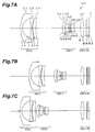
- Figs. 7A to 7C show the structure of the zoom lens system ZL4 in accordance with Example 4 of the present invention.
- the first lens group G1 is composed of, in order from the object along the optical axis, a negative meniscus lens L11 having a convex surface facing the object, a double concave negative lens L12, and a positive meniscus lens L13 having a convex surface facing the object, while the image-side lens surface of the negative meniscus lens L11 (surface No. 2) is formed aspherical.
- the second lens group G2 is composed of, in order from the object along the optical axis, a double convex positive lens L21, a cemented lens constructed by cementing a positive meniscus lens L22 having a convex surface facing the object and a negative meniscus lens L23 having a convex surface facing the object together, and a cemented lens constructed by cementing a negative meniscus lens L24 having a convex surface facing the object and a positive meniscus lens L25 having a convex surface facing the object together, while the object-side lens surface of the positive meniscus lens L21 (surface No. 7) is formed aspherical.
- the third lens group G3 is constructed by a double convex positive lens L31 alone.
- the F-number determining member S is arranged on the image side of the vertex on the optical axis of the positive lens L22 in the second lens group G2 and moves together with the second lens group G2 when varying power from the wide-angle end state to the telephoto end state.
- the filter group FL is constructed by a low-pass filter, an infrared cut filter, and the like.
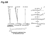
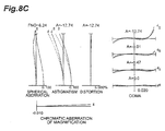
- Figs. 8A to 8C are aberration charts showing various aberrations in the zoom lens system ZL4 in accordance with Example 4 in the infinity in-focus state in the wide-angle end, intermediate focal length, and telephoto end states, respectively.
- the aberration charts show that various aberrations are favorably corrected in each focal length state from the wide-angle end state to the telephoto end state, so that the zoom lens system ZL4 in accordance with Example 4 has excellent optical performances.
- Figs. 9A to 9C show the structure of the zoom lens system ZL5 in accordance with Example 5 of the present invention.
- the first lens group G1 is composed of, in order from the object along the optical axis, a negative meniscus lens L11 having a convex surface facing the object, a double concave negative lens L12, and a positive meniscus lens L13 having a convex surface facing the object, while the image-side lens surface of the negative meniscus lens L11 (surface No. 2) is formed aspherical.
- the second lens group G2 is composed of, in order from the object along the optical axis, a positive meniscus lens L21 having a convex surface facing the object, a cemented lens constructed by cementing a double convex positive lens L22 and a double concave negative lens L23 together, and a cemented lens constructed by cementing a negative meniscus lens L24 having a convex surface facing the object and a double convex positive lens L25 together, while the object-side lens surface of the positive meniscus lens L21 (surface No. 7) is formed aspherical.
- the third lens group G3 is constructed by a double convex positive lens L31 alone.
- the F-number determining member S is arranged on the image side of the vertex on the optical axis of the positive lens L22 in the second lens group G2 and moves together with the second lens group G2 when varying power from the wide-angle end state to the telephoto end state.
- the filter group FL is constructed by a low-pass filter, an infrared cut filter, and the like.
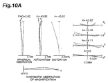
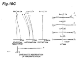
- Figs. 10A to 10C are aberration charts showing various aberrations in the zoom lens system ZL5 in accordance with Example 5 in the infinity in-focus state in the wide-angle end, intermediate focal length, and telephoto end states, respectively.
- the aberration charts show that various aberrations are favorably corrected in each focal length state from the wide-angle end state to the telephoto end state, so that the zoom lens system ZL5 in accordance with Example 5 has excellent optical performances.
- each of the above-mentioned Examples can provide a compact zoom lens system ZL, suitable for solid-state imaging devices, having excellent performances while achieving a wide angle and a high variable power ratio.
Landscapes
- Physics & Mathematics (AREA)
- General Physics & Mathematics (AREA)
- Optics & Photonics (AREA)
- Lenses (AREA)
- Studio Devices (AREA)
Applications Claiming Priority (1)
| Application Number | Priority Date | Filing Date | Title |
|---|---|---|---|
| JP2007331793A JP5309553B2 (ja) | 2007-12-25 | 2007-12-25 | ズームレンズ、及び、このズームレンズを備えた光学機器 |
Publications (3)
| Publication Number | Publication Date |
|---|---|
| EP2075614A2 EP2075614A2 (en) | 2009-07-01 |
| EP2075614A3 EP2075614A3 (en) | 2009-08-05 |
| EP2075614B1 true EP2075614B1 (en) | 2016-10-26 |
Family
ID=40512469
Family Applications (1)
| Application Number | Title | Priority Date | Filing Date |
|---|---|---|---|
| EP08171775.3A Expired - Fee Related EP2075614B1 (en) | 2007-12-25 | 2008-12-16 | Zoom lens system |
Country Status (4)
| Country | Link |
|---|---|
| US (1) | US7675688B2 (zh) |
| EP (1) | EP2075614B1 (zh) |
| JP (1) | JP5309553B2 (zh) |
| CN (1) | CN101470254B (zh) |
Families Citing this family (11)
| Publication number | Priority date | Publication date | Assignee | Title |
|---|---|---|---|---|
| JP5168638B2 (ja) * | 2008-04-22 | 2013-03-21 | 株式会社ニコン | レンズ系及びこれを搭載する光学機器 |
| US8587875B2 (en) | 2008-07-14 | 2013-11-19 | Nikon Corporation | Zoom lens, optical apparatus and method for manufacturing zoom lens |
| JP5298878B2 (ja) * | 2009-01-22 | 2013-09-25 | 株式会社リコー | 結像レンズおよびカメラ装置および携帯情報端末装置 |
| JP5825109B2 (ja) * | 2011-01-26 | 2015-12-02 | 株式会社ニコン | ズームレンズおよび光学機器 |
| JP5676505B2 (ja) | 2011-04-07 | 2015-02-25 | パナソニックIpマネジメント株式会社 | ズームレンズ系、撮像装置及びカメラ |
| CN203909389U (zh) | 2011-12-09 | 2014-10-29 | 富士胶片株式会社 | 变焦透镜和摄像装置 |
| WO2013084494A1 (ja) * | 2011-12-09 | 2013-06-13 | 富士フイルム株式会社 | ズームレンズおよび撮像装置 |
| WO2013128882A1 (ja) * | 2012-02-28 | 2013-09-06 | 株式会社ニコン | 光学系、光学機器及び光学系の製造方法 |
| JP5987543B2 (ja) * | 2012-08-08 | 2016-09-07 | 株式会社ニコン | ズームレンズ、光学装置 |
| US9971132B2 (en) * | 2016-04-25 | 2018-05-15 | Young Optics Inc. | Zoom lens |
| US10935783B1 (en) * | 2019-09-17 | 2021-03-02 | Aquabyte, Inc. | Optical system for capturing digital images in an aquaculture environment in situ |
Family Cites Families (20)
| Publication number | Priority date | Publication date | Assignee | Title |
|---|---|---|---|---|
| JPS6287925A (ja) * | 1985-10-14 | 1987-04-22 | Canon Inc | ズ−ムレンズ |
| US4828372A (en) * | 1987-10-09 | 1989-05-09 | Eastman Kodak Company | Wide-angle zoom lens |
| JP3486532B2 (ja) * | 1997-08-04 | 2004-01-13 | キヤノン株式会社 | 振動補償機能を有したズームレンズ及びそれを有するカメラ |
| JP2002072091A (ja) * | 2000-08-29 | 2002-03-12 | Minolta Co Ltd | ズームレンズ |
| JP2002072093A (ja) * | 2000-08-31 | 2002-03-12 | Minolta Co Ltd | ズームレンズ |
| JP3698134B2 (ja) * | 2002-08-30 | 2005-09-21 | 株式会社ニコン | ズームレンズ |
| CN1977205A (zh) * | 2004-06-29 | 2007-06-06 | 松下电器产业株式会社 | 变焦透镜系统、成像装置和拍摄设备 |
| JP2006078581A (ja) * | 2004-09-07 | 2006-03-23 | Sony Corp | ズームレンズ及び撮像装置 |
| JP4892892B2 (ja) * | 2004-09-15 | 2012-03-07 | 株式会社ニコン | 広角ズームレンズ |
| JP4612823B2 (ja) * | 2004-09-16 | 2011-01-12 | キヤノン株式会社 | ズームレンズ及びそれを有する撮像装置 |
| JP4947990B2 (ja) | 2005-02-21 | 2012-06-06 | オリンパス株式会社 | 撮像装置及びそれを備えた電子機器 |
| JP4882263B2 (ja) * | 2005-03-31 | 2012-02-22 | 株式会社ニコン | ズームレンズ |
| US7336428B2 (en) * | 2005-04-19 | 2008-02-26 | Olympus Imaging Corp. | Zoom lens system and electronic image pickup apparatus using the same |
| JP4914136B2 (ja) * | 2005-09-06 | 2012-04-11 | キヤノン株式会社 | ズームレンズ及びそれを有する撮像装置 |
| JP2007072263A (ja) * | 2005-09-08 | 2007-03-22 | Konica Minolta Photo Imaging Inc | 変倍光学系 |
| JP4902179B2 (ja) * | 2005-11-29 | 2012-03-21 | キヤノン株式会社 | ズームレンズ及びそれを有する撮像装置 |
| JP4884783B2 (ja) * | 2006-01-19 | 2012-02-29 | 富士フイルム株式会社 | 結像変倍光学系およびこれを用いた撮像装置 |
| US7310191B2 (en) * | 2006-03-09 | 2007-12-18 | Matsushita Electric Industrial Co., Ltd. | Zoom lens system, imaging device and camera |
| JP4916198B2 (ja) * | 2006-03-20 | 2012-04-11 | 株式会社リコー | ズームレンズ、ズームレンズを有する撮像装置、カメラ装置および携帯情報端末装置 |
| JP4923764B2 (ja) * | 2006-06-12 | 2012-04-25 | 株式会社ニコン | ズームレンズとこれを有する光学装置 |
-
2007
- 2007-12-25 JP JP2007331793A patent/JP5309553B2/ja not_active Expired - Fee Related
-
2008
- 2008-12-15 US US12/335,222 patent/US7675688B2/en not_active Expired - Fee Related
- 2008-12-16 EP EP08171775.3A patent/EP2075614B1/en not_active Expired - Fee Related
- 2008-12-25 CN CN2008101885882A patent/CN101470254B/zh not_active Expired - Fee Related
Also Published As
| Publication number | Publication date |
|---|---|
| CN101470254B (zh) | 2012-11-14 |
| US20090161229A1 (en) | 2009-06-25 |
| JP2009156905A (ja) | 2009-07-16 |
| JP5309553B2 (ja) | 2013-10-09 |
| US7675688B2 (en) | 2010-03-09 |
| EP2075614A3 (en) | 2009-08-05 |
| CN101470254A (zh) | 2009-07-01 |
| EP2075614A2 (en) | 2009-07-01 |
Similar Documents
| Publication | Publication Date | Title |
|---|---|---|
| EP2075614B1 (en) | Zoom lens system | |
| US7872808B2 (en) | Zoom lens system and camera including the same | |
| US8144403B2 (en) | Zoom lens system, optical apparatus, and method for zooming | |
| JP4923764B2 (ja) | ズームレンズとこれを有する光学装置 | |
| EP2075613B1 (en) | Zoom optical system, optical instrument incorporating the zoom optical system, and method of manufacturing the zoom optical system | |
| US8339501B2 (en) | Zoom lens system, imaging device and camera | |
| US7688520B2 (en) | Zoom lens system and camera including the same | |
| EP1881357A1 (en) | Vibration-proof telephoto zoom lens having four lens groups | |
| US8446520B2 (en) | Zoom lens system, imaging device and camera | |
| JP5110451B2 (ja) | ズームレンズ、光学機器及びズームレンズの製造方法 | |
| EP3252519B1 (en) | Zoom lens, optical apparatus, and zoom lens production method | |
| US8199415B2 (en) | Zoom lens system, optical device with zoom lens system, and method of manufacturing zoom lens system | |
| US7457047B2 (en) | Zoom optical system and imaging apparatus using the same | |
| EP2098899B1 (en) | Zoom lense and optical apparatus equipped with this zoom lens | |
| JP5403316B2 (ja) | ズームレンズ系、及び、このズームレンズ系を備えた光学機器 | |
| US8379319B2 (en) | Zoom lens, optical apparatus and method for manufacturing zoom lens | |
| US9140882B2 (en) | Zoom lens, optical apparatus, and method for manufacturing the zoom lens | |
| US8064144B2 (en) | Zoom lens system, imaging device and camera | |
| JP5505770B2 (ja) | ズームレンズ、光学機器 | |
| US8432618B2 (en) | Zoom lens system, imaging device and camera | |
| JP5115871B2 (ja) | ズームレンズ、光学機器及びズームレンズの製造方法 | |
| EP1967883B1 (en) | Zoom lens of the telephoto type and having four lens groups | |
| JP5115870B2 (ja) | ズームレンズ、光学機器及びズームレンズの製造方法 |
Legal Events
| Date | Code | Title | Description |
|---|---|---|---|
| PUAI | Public reference made under article 153(3) epc to a published international application that has entered the european phase |
Free format text: ORIGINAL CODE: 0009012 |
|
| AK | Designated contracting states |
Kind code of ref document: A2 Designated state(s): AT BE BG CH CY CZ DE DK EE ES FI FR GB GR HR HU IE IS IT LI LT LU LV MC MT NL NO PL PT RO SE SI SK TR |
|
| AX | Request for extension of the european patent |
Extension state: AL BA MK RS |
|
| PUAL | Search report despatched |
Free format text: ORIGINAL CODE: 0009013 |
|
| AK | Designated contracting states |
Kind code of ref document: A3 Designated state(s): AT BE BG CH CY CZ DE DK EE ES FI FR GB GR HR HU IE IS IT LI LT LU LV MC MT NL NO PL PT RO SE SI SK TR |
|
| AX | Request for extension of the european patent |
Extension state: AL BA MK RS |
|
| 17P | Request for examination filed |
Effective date: 20100204 |
|
| AKX | Designation fees paid |
Designated state(s): DE FR GB |
|
| RAP1 | Party data changed (applicant data changed or rights of an application transferred) |
Owner name: NIKON CORPORATION |
|
| 17Q | First examination report despatched |
Effective date: 20121012 |
|
| RAP1 | Party data changed (applicant data changed or rights of an application transferred) |
Owner name: NIKON CORPORATION |
|
| GRAP | Despatch of communication of intention to grant a patent |
Free format text: ORIGINAL CODE: EPIDOSNIGR1 |
|
| INTG | Intention to grant announced |
Effective date: 20160512 |
|
| RIN1 | Information on inventor provided before grant (corrected) |
Inventor name: SHIMADA, TOSHIYUKI |
|
| GRAS | Grant fee paid |
Free format text: ORIGINAL CODE: EPIDOSNIGR3 |
|
| GRAA | (expected) grant |
Free format text: ORIGINAL CODE: 0009210 |
|
| AK | Designated contracting states |
Kind code of ref document: B1 Designated state(s): DE FR GB |
|
| REG | Reference to a national code |
Ref country code: GB Ref legal event code: FG4D |
|
| REG | Reference to a national code |
Ref country code: DE Ref legal event code: R096 Ref document number: 602008047005 Country of ref document: DE |
|
| REG | Reference to a national code |
Ref country code: FR Ref legal event code: PLFP Year of fee payment: 9 |
|
| REG | Reference to a national code |
Ref country code: DE Ref legal event code: R097 Ref document number: 602008047005 Country of ref document: DE |
|
| PLBE | No opposition filed within time limit |
Free format text: ORIGINAL CODE: 0009261 |
|
| STAA | Information on the status of an ep patent application or granted ep patent |
Free format text: STATUS: NO OPPOSITION FILED WITHIN TIME LIMIT |
|
| 26N | No opposition filed |
Effective date: 20170727 |
|
| REG | Reference to a national code |
Ref country code: FR Ref legal event code: PLFP Year of fee payment: 10 |
|
| PGFP | Annual fee paid to national office [announced via postgrant information from national office to epo] |
Ref country code: GB Payment date: 20201210 Year of fee payment: 13 Ref country code: DE Payment date: 20201201 Year of fee payment: 13 Ref country code: FR Payment date: 20201112 Year of fee payment: 13 |
|
| REG | Reference to a national code |
Ref country code: DE Ref legal event code: R119 Ref document number: 602008047005 Country of ref document: DE |
|
| GBPC | Gb: european patent ceased through non-payment of renewal fee |
Effective date: 20211216 |
|
| PG25 | Lapsed in a contracting state [announced via postgrant information from national office to epo] |
Ref country code: GB Free format text: LAPSE BECAUSE OF NON-PAYMENT OF DUE FEES Effective date: 20211216 Ref country code: DE Free format text: LAPSE BECAUSE OF NON-PAYMENT OF DUE FEES Effective date: 20220701 |
|
| PG25 | Lapsed in a contracting state [announced via postgrant information from national office to epo] |
Ref country code: FR Free format text: LAPSE BECAUSE OF NON-PAYMENT OF DUE FEES Effective date: 20211231 |