EP2075192B1 - Aussenbordmotor - Google Patents
Aussenbordmotor Download PDFInfo
- Publication number
- EP2075192B1 EP2075192B1 EP08022405A EP08022405A EP2075192B1 EP 2075192 B1 EP2075192 B1 EP 2075192B1 EP 08022405 A EP08022405 A EP 08022405A EP 08022405 A EP08022405 A EP 08022405A EP 2075192 B1 EP2075192 B1 EP 2075192B1
- Authority
- EP
- European Patent Office
- Prior art keywords
- upper casing
- outboard motor
- mounting plate
- disposed
- transmission
- Prior art date
- Legal status (The legal status is an assumption and is not a legal conclusion. Google has not performed a legal analysis and makes no representation as to the accuracy of the status listed.)
- Active
Links
Images
Classifications
-
- B—PERFORMING OPERATIONS; TRANSPORTING
- B63—SHIPS OR OTHER WATERBORNE VESSELS; RELATED EQUIPMENT
- B63H—MARINE PROPULSION OR STEERING
- B63H20/00—Outboard propulsion units, e.g. outboard motors or Z-drives; Arrangements thereof on vessels
- B63H20/14—Transmission between propulsion power unit and propulsion element
- B63H20/22—Transmission between propulsion power unit and propulsion element allowing movement of the propulsion element about at least a horizontal axis without disconnection of the drive, e.g. using universal joints
-
- B—PERFORMING OPERATIONS; TRANSPORTING
- B63—SHIPS OR OTHER WATERBORNE VESSELS; RELATED EQUIPMENT
- B63H—MARINE PROPULSION OR STEERING
- B63H20/00—Outboard propulsion units, e.g. outboard motors or Z-drives; Arrangements thereof on vessels
- B63H20/02—Mounting of propulsion units
-
- B—PERFORMING OPERATIONS; TRANSPORTING
- B63—SHIPS OR OTHER WATERBORNE VESSELS; RELATED EQUIPMENT
- B63H—MARINE PROPULSION OR STEERING
- B63H20/00—Outboard propulsion units, e.g. outboard motors or Z-drives; Arrangements thereof on vessels
- B63H20/14—Transmission between propulsion power unit and propulsion element
- B63H20/20—Transmission between propulsion power unit and propulsion element with provision for reverse drive
-
- B—PERFORMING OPERATIONS; TRANSPORTING
- B63—SHIPS OR OTHER WATERBORNE VESSELS; RELATED EQUIPMENT
- B63H—MARINE PROPULSION OR STEERING
- B63H20/00—Outboard propulsion units, e.g. outboard motors or Z-drives; Arrangements thereof on vessels
- B63H20/32—Housings
Definitions
- the present invention relates to an outboard motor according to the preamble part of claim 1.
- the present invention relates to an outboard motor having a mechanism for transmitting engine power to a propeller through a shaft, and especially relates to an outboard motor equipped with a transmission for changing the rotational speed of a shaft.
- engine power is transmitted to a crankshaft, a drive shaft, and a propeller shaft, and then is transmitted to a propeller from the propeller shaft.
- the engine power is transmitted to the propeller through each of the aforementioned shafts.
- the engine power is adjusted to change the rotational speed of each shaft, so that the rotational speed of the propeller is changed subsequently to cause the speed change in the watercraft.
- a conventional outboard motor has a plurality of mounts for supporting the outboard motor to a hull, and especially has two upper mounts and two lower mounts.
- the two upper mounts are often disposed on a mounting plate provided above an upper casing that supports a drive shaft therein while having a short distance therebetween.
- the two upper mounts of the outboard motor are disposed on the mounting plate provided above the upper casing while having the short distance therebetween, the mounting plate as well as an upper section of the upper casing that is joined to the mounting plate become narrow in width. Meanwhile, a transmission that is mounted on the drive shaft and disposed in the upper casing has a considerable width. Thus, if the upper section of the upper casing is narrowed, the transmission cannot be inserted from above the upper casing during disposition of the transmission in the upper casing. Consequently, problems arise such as a complicated structure of the upper casing and a troublesome assembly work. The transmission has to be inserted from another insertion opening such as one separately provided for the transmission in order to dispose the transmission in the upper casing. In addition, there is a case that the transmission has to be mounted on the drive shaft after being inserted in the upper casing.
- the outboard motor in which the upper mounts and the lower mounts are disposed on different members such that the upper mounts are disposed on the mounting plate and that the lower mounts are disposed on the upper casing, first, the outboard motor has to be detached from the hull along with the mounting plate and the upper casing in order to take out the transmission from the outboard motor during maintenance of the transmission. Then, after the outboard motor is detached from the hull, the transmission is taken out for the maintenance. This causes a problem to complicate the maintenance work.
- the engine, the mounting plate, and the upper casing are jointly secured by a through bolt from the upper casing side. Still further, the mounting plate and the upper casing are secured by another bolt.
- the conventional outboard motors there are ones that are supported to the hull by the upper mounts disposed on the mounting plate and by the lower mounts disposed on a lower section of the upper casing.
- the engine when only the engine is disassembled for maintenance, the engine can be removed by unscrewing the through bolts while the outboard motor remains supported to the hull by each of the mounts.
- the positions of the through bolts are determined according to the exterior shape of the engine. Therefore, it was difficult to enlarge only the upper casing, for example.
- the present invention has been made in view of the foregoing circumstances.
- an outboard motor comprising: an upper casing; a lower casing by which a propeller shaft is pivotally supported, the lower casing being positioned below the upper casing; a mounting plate to which an engine is mounted, the mounting plate being disposed on a top surface of the upper casing; and at least one upper mount and at least one lower mount being configured to mount the outboard motor to a hull, wherein at least the upper mount is disposed on a lateral outer surface of the upper casing.
- the upper mount is disposed on an upper lateral surface of the upper casing
- the lower mount is disposed on a lower lateral surface of the upper casing.
- two upper mounts are disposed on two substantially opposite, lateral surfaces of the upper casing, and/or two lower mounts are disposed on two substantially opposite, lateral surfaces of the upper casing.
- the lower mount is disposed on a lateral outer surface of the upper casing.
- a transmission is arranged between the engine and the propeller shaft, said transmission being preferably located in the upper casing.
- the engine which is mounted on the mounting plate, has a vertically arranged crankshaft whose rotation is transmittable to a drive shaft pivotally supported in the upper casing.
- the transmission is mounted on the drive shaft to change a rotation speed thereof and to transmit the rotation to the propeller shaft pivotally supported in the lower casing.
- a top surface of the upper casing is formed with a top surface opening which is covered by the mounting plate.
- the transmission is insertable from above through the top surface opening.
- the mounting plate is disposed on the upper casing such that the transmission is attached to a bottom surface of the mounting plate and the engine is attached to a top surface of the mounting plate.
- the upper casing is provided with a divider dividing an inside of the upper casing into a front chamber and a rear chamber, and, preferably, the transmission is disposed in the front chamber.
- a boat comprising a hull to which an outboard motor according to one of the above embodiments is pivotally mounted.
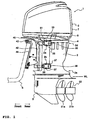
- FIG. 1 is a left side view showing an outboard motor according to an embodiment.
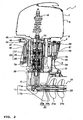
- FIG. 2 is a longitudinal sectional view showing the outboard motor of FIG. 1 according to the embodiment where the outboard motor is cut by a vertical plane that is parallel with a traveling direction of a watercraft.
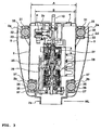
- FIG. 3 is a longitudinal sectional view showing the outboard motor of FIG. 1 according to the embodiment where a front chamber of an upper casing is cut by a vertical plane that is perpendicular to the traveling direction of the watercraft.
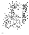
- FIG. 4 is an exploded perspective view of the upper casing and its surrounding members of the outboard motor of FIG 1 according to the embodiment.
- a lower casing 3 is provided below an upper casing 2, and an engine 5 is mounted above the upper casing 2 via a generally flat mounting plate 4.
- the engine 5 is, for example, a water-cooled V6 engine and is mounted on the mounting plate 4 in a manner that a crankshaft 6 thereof is in a vertical position.
- the engine 5 is covered by a detachable upper cover 7 and a detachable lower cover 8. As shown in FIG. 3 , a right side surface and a left side surface of the upper casing 2 are covered by a side cover 9, which is also detachable.
- the engine 5 is fixed to the mounting plate 4 in a manner that a plurality of fixing bolts (not shown) are inserted and fastened in a plurality of engine-side bolt holes (not shown) formed in the engine 5 and in a plurality of engine fastening bolt holes 4a (bolted positions) formed in the mounting plate 4. Then, the crankshaft 6 is disposed on the inside of the plurality of engine fastening bolt holes (bolted positions) 4a, that is, on the inside of an area surrounded by the plurality of engine fastening bolt holes 4a.
- the upper casing 2 is a box body made of metal such as aluminum alloy, and the mounting plate 4 is disposed on a top surface thereof.
- the mounting plate 4 and the upper casing 2 are securely fastened in a manner that a plurality of fixing bolts (not shown) is inserted in a plurality of upper-case fastening bolt holes 4b arranged on the edge, which is located outside the plurality of engine fastening bolt holes (bolted positions) 4a formed in the mounting plate 4, and in a plurality of upper-casing side bolt holes 2i located on the edge of the top surface of the upper casing 2.
- the lower casing 3 is fixed to a bottom surface of the upper casing 2 by fixing bolts, which are not shown.
- the width of a front chamber 2g in an upper section 2d of the upper casing 2 (a width A of an upper surface opening 2c, which will be described later) can be set large (thick) by disposing upper mounts 31, which will be described later, on upper lateral surfaces 2a on the right and the left of the upper casing 2.
- the front chamber 2g is formed large in width according to the size and shape of a transmission 25 so that the transmission 25, which will be described later, can be inserted therein from above.
- a lower section 2e of the upper casing 2 is formed small (thin) in width in accordance with a joined surface of the lower casing 3 to which the lower section 2e is joined.
- the upper casing 2 is divided by a divider 2f into a front chamber and a rear chamber (the front and rear in the traveling direction of the watercraft indicated by the arrow in FIG. 1 ).
- the front chamber 2g forward chamber is a space in which a drive shaft 10, the transmission 25, and the like are disposed.
- a rear chamber 2h (rearward chamber) is a space to dispose therein an oil pan 51 for housing lubricating oil, an oil pan cover 52 to lid the oil pan 51, an exhaust pipe 53 that is mounted to communicate with an exhaust hole 51 a formed in the oil pan 51 and that lets exhaust gases discharged from the engine pass through, an exhaust expansion chamber 54 for expanding the exhaust gases passed through the exhaust pipe 53, an exhaust chamber cover 55 disposed between the exhaust expansion chamber 54 and the exhaust pipe 53, a drain pipe (not shown) through which cooling water drawn by a water pump P, which will be described later, and supplied to the engine 5 is discharged, and the like.
- the engine is lubricated with the oil housed in the oil pan 51.
- the exhaust gases discharged from the engine flow to an exhaust passage 23, which will be described later, via the exhaust pipe 53 and the expansion chamber 54, is mixed with cooling water to be discharged, and is discharged together in the water.
- the divider 2f of the upper casing 2 is formed in a structure with material and thickness suited to prevent the front chamber 2g from receiving influences of the rear chamber 2h with possible danger of oil or water leakage at a high temperature.
- the divider 2f divides the upper casing 2 into the front and the rear, it serves to increase the rigidity of the upper casing 2 against twists and the like.
- the vertical drive shaft 10 is pivotally supported in the front chamber 2g of the upper casing 2.
- the upper end of the drive shaft 10 is coupled to the lower end of the crankshaft 6 of the engine 5 by spline-fitting.
- the drive shaft 10 extends downward in the upper casing 2, reaches the inside of the lower casing 3, and links to a propeller shaft 20 pivotally supported in the lower casing 3 in a horizontal manner via a bevel gear mechanism 11.
- the transmission 25 is provided in the front chamber 2g of the upper casing 2.
- the transmission 25 is mounted on the drive shaft 10 and is constituted to house a speed-changing planetary gear mechanism 27 and a forward/reverse switch 28 in a transmission case 26 that makes up an outer shell of the transmission 25.
- a final deceleration device 29 that utilizes a planetary gear mechanism is provided right under the transmission 25.
- the propeller shaft 20 is a double-rotary shaft that coaxially combines an outer shaft 20a with an inner shaft 20b.
- a drive bevel gear 11 a of the bevel gear mechanism 11 rotates as a unit with the drive shaft 10
- a driven bevel gear 11 b thereof rotates as a unit with the outer shaft 20a
- a driven bevel gear 11c thereof rotates as a unit with an inner shaft 20b.
- a first propeller 21 a is fixed to the outer shaft 20a
- a second propeller 21 b is fixed to the inner shaft 20b.
- These propellers make up a contra-rotating propeller mechanism 22.
- An exhaust passage 23 is formed in the axes of the first propeller 21 a and the second propeller 21 b.
- the water pump P to draw cooling water for the engine 5 is disposed in the upper casing 2, for example, in the right side thereof in the traveling direction of the watercraft.
- An installation position of the water pump P is higher than that of the transmission 25 and is also sufficiently higher than a waterline WL during operation of the outboard motor 1 of a boat (see FIGs. 1 and 3 ).
- the outboard motor 1 constituted as described above, when the engine 5 is activated, the rotation of the crankshaft 6 is transmitted to the drive shaft 10, and the rotation of the drive shaft 10 is changed its speed and switched to the forward/reverse direction in the transmission 25. Furthermore, the rotation of the drive shaft 10 is decelerated by the final deceleration device 29 and is transmitted to the propeller shaft 20. Then, a pair of the outer shaft 20a of the propeller shaft 20 and the first propeller 21 a and a pair of the inner shaft 20b and the second propeller 21 b rotate in opposite directions to produce high propulsive force.
- the outboard motor 1 is supported to a hull S of the boat via the upper mount 31 disposed in the upper casing 2 and a lower mount 35 also disposed in the upper casing 2.
- the two upper mounts 31 are included, and the two upper mounts 31 are disposed on the upper lateral (outer) surfaces 2a in the right and the left of the upper section 2d of the upper casing 2. Then, the upper mounts 31 are held against the upper lateral surfaces 2a from the right and left outside with upper-mount holding members 32 and are fixed by upper-mount mounting bolts 33.
- the two lower mounts 35 are included in this embodiment, and the two lower mounts 35 are disposed on lower lateral (outer) surfaces 2b in the right and left of the lower section 2e of the upper casing 2. Then, the lower mounts 35 are held against the lower lateral surfaces 2b from the right and left outside with lower-mount holding members 36 and are fixed by lower-mount mounting bolts 37.
- a steering bracket 45 is fixedly coupled to a front section of the outboard motor 1 via the upper mounts 31 and the lower mounts 35. Then, the steering bracket 45 is coupled to a swivel bracket 42 by a vertical steering shaft 41 shown in FIG. 2 .
- the swivel bracket 42 is coupled to a clamp bracket 44 via a horizontal tilt shaft 43 and a lock mechanism, which is not shown.
- the clamp bracket 44 is fixed to a transom of the hull S.
- the outboard motor 1 can steer the hull S by pivoting to the right and the left about the steering shaft 41, and can also be tilted up above the water surface by pivoting vertically about the tilt shaft 43.
- a pair of the right and left upper mounts 31 and a pair of the right and left lower mounts 35 in this embodiment support the weight of the outboard motor 1, and increase a spring constant by increasing hardness of elastic members such as rubber disposed in the upper mounts 31 and the lower mounts 35 in order to facilitate the transmission of the propulsive force obtained by the outboard motor 1 to the hull S.
- the two upper mounts 31 are disposed on the upper lateral surfaces 2a of the upper casing 2.
- a distance between the two upper mounts 31 is widened.
- the width A (length perpendicular to the traveling direction of the watercraft) of the top surface opening 2c that opens in the top surface of the upper casing 2 can be set wider (longer) than a width B (length perpendicular to the traveling direction of the watercraft) of the transmission 25.
- the transmission 25 can be inserted in the upper casing 2 from above during assembly of the outboard motor 1. Consequently, the installation work of the transmission 25 can be facilitated.
- the transmission 25 can be inserted and disposed in the upper casing 2 from above the upper casing 2 through the top surface opening 2c.
- the upper casing 2 can simply be constituted.
- the transmission 25 is attached in advance to the bottom surface of the mounting plate 4, and the transmission 25 and the mounting plate 4 in the above condition are inserted in the upper casing 2 from above through the top surface opening 2c. Accordingly, the number of works to be performed after the insertion of the transmission in the upper casing 2 can be reduced. Therefore, it is possible to further simplify works related to the insertion and disposition of the transmission 25 during the assembly of the outboard motor 1.
- the transmission 25 is attached to the bottom surface of the mounting plate 4, the engine 5 is attached to the top surface of the mounting plate 4. Then, these components are integrally disposed in the upper casing 2. Consequently, the number of works to be performed after the insertion of the transmission 25 in the upper casing 2 can further be reduced. Therefore, it is possible to further simplify the works related to the insertion and disposition of the transmission 25 during the assembly of the outboard motor 1.
- the two upper mounts 31 and the two lower mounts 35 are all disposed on the upper casing 2. Accordingly, when the engine 5 or the transmission 25 has to be removed from the outboard motor 1 for maintenance and the like, the engine 5, the mounting plate 4, the transmission 25, and the like can be removed from the outboard motor 1 while the upper case 2 remains supported to the hull S. Consequently, the maintenance works can be simplified, and thus, the maintenance can be performed effectively.
- the transmission 25 when the transmission 25 is inserted and disposed in the upper casing 2 while being attached to the bottom surface of the mounting plate 4, the transmission 25 can further easily be removed from the outboard motor 1. Therefore, the maintenance can be performed further effectively.
- the two upper mounts 31 and the two lower mounts 35 are included to support the outboard motor 1 to the hull S, and the upper mounts 31 are disposed on the upper lateral surfaces 2a of the upper casing 2.
- the upper mounts 31 are disposed on the upper lateral surfaces 2a of the upper casing 2.
- the lower mounts 35 are disposed on the lower lateral surfaces 2b of the upper casing 2
- the upper mounts 31 and the lower mounts 35 are both disposed on the upper casing 2. Accordingly, during the maintenance, it is possible to take out the mounting plate 4, the engine 5, and the transmission 25 while the upper casing 2 remains supported to the hull S. Consequently, the upper casing 2 for disposing the transmission 25 therein can have a simple structure. It is also possible to simplify the assembly and maintenance works.
- the top surface of the upper casing 2 is formed with the top surface opening 2c through which the transmission 25 can be inserted from above and which is covered with the mounting plate 4. Therefore, the transmission 25 can be inserted and disposed in the upper casing 2 from the top surface opening 2c while the transmission 25 is attached to the mounting plate 4. Consequently, it is possible to further simplify the insertion and disposition of the transmission 25 in the upper casing 2.
- the mounting plate 4 is disposed on the upper casing 2 while the transmission 25 is attached to the bottom surface of the mounting plate 4, and the engine 5 is attached to the top surface of the mounting plate 4.
- the assembly work can further be simplified by simultaneously disposing the engine 5 and the transmission 25.
- the divider 2f to divide the inside of the upper casing 2 into the front chamber and the rear chamber is provided, and the transmission 25 is disposed in the front chamber 2g. Therefore, it can facilitate the disposition of the transmission 25 in a given position in the upper casing 2 and can suppress influences of the components disposed in the rear chamber 2h (heat, oil content, and moisture, for example) to the transmission 25.
- the engine 5 is bolted on the mounting plate 4, and the crankshaft 6 is disposed on the inside of the bolted positions 4a.
- the mounting plate 4 and the upper casing 2 are bolted on the outside of the bolted positions 4a. This facilitates the setting of the fastening force.
- since the number of members to be fastened is reduced, it is possible to suppress weakening of the fastening force due to change over time. Furthermore, it produces an effect of more freedom in design of the upper casing 2.
- a mating surface between the engine 5 and the mounting plate 4 is formed with the cooling water passage (not shown) for cooling water to be supplied from the water pump P to the engine 5, an oil passage (not shown) for the lubricating oil supplied from the oil pan 51 to the engine 5, an exhaust passage (not shown) through which exhaust gases discharged from the engine 5 pass, and the like. Therefore, it is desirable to increase the fastening force between the two components and to minimize change in the fastening force over time.
- the upper mounts 31 are disposed in the upper section of the upper casing 2
- the lower mounts 35 are disposed in the lower section of the upper casing 2
- the engine 5 is bolted on the mounting plate 4
- the mounting plate 4 is secured to the upper casing 2 by other bolts. Therefore, the engine 5 and the upper casing 2 are independently secured to the mounting plate 4.
- the mounting plate 4 and the engine 5 can be removed while the outboard motor 1 remains supported by mounts. Furthermore, the exterior shape of the upper casing 2 can be designed without consideration of that of the engine 5. Therefore, it can produce the effect of further freedom in design. Accordingly, it becomes possible to set the top surface opening 2c of the upper casing 2 so large that the transmission 25 and the like can be mounted in the upper casing 2 from above the upper casing 2.
- the transmission 25 disposed in the upper casing 2 is not limited to one described in this embodiment, and one with broader width or one in a different shape may be disposed, for example.
- the upper casing 2 with the upper section 2d in further broader width, or the upper casing 2 with the upper section 2d that is formed to conform to the transmission 25 may be prepared.
- the outboard motor 1 comprises the upper casing 2, and the lower casing 3, by which the propeller shaft 20 is pivotally supported, is positioned below the upper casing 2.
- the mounting plate 4, to which the engine 5 is mounted, is positioned above the upper casing 2.
- At least one upper mount 31 and at least one lower mount 35 are configured to mount the outboard motor 1 to the hull 5, wherein at least the upper mount 31 is disposed on a lateral outer surface of the upper casing zoo 21.
- the upper mount 31 is disposed on an upper lateral surface of the upper casing 2
- the lower mount 35 is disposed on a lower lateral surface of the upper casing 2.
- two upper mounts 31 are disposed on two substantially opposite, lateral surfaces of the upper casing 2, and/or two lower mounts 35 are disposed on two substantially opposite, lateral surfaces of the upper casing 2.
- the lower mount 35 is disposed on a lateral outer surface of the upper casing 2.
- the transmission 25 is arranged between the engine 5 and the propeller shaft 20, and said transmission 25 is preferably located in the upper casing 2.
- an outboard motor constituted in which a lower casing is provided below an upper casing, a mounting plate is provided above the upper casing, an engine with a vertically-arranged crankshaft is mounted on the mounting plate, and rotation of the crankshaft is transmitted to a drive shaft pivotally supported in the upper casing, is changed its speed in a transmission mounted on the drive shaft, and is transmitted to a propeller shaft pivotally supported in the lower casing, wherein the outboard motor has an upper mount and a lower mount for supporting the outboard motor to a hull, the upper mount is disposed on an upper lateral surface of the upper casing, and the lower mount is disposed on a lower lateral surface of the upper casing.
- the outboard motor has the upper mount and the lower mount for supporting the outboard motor to the hull, and the upper mount is disposed on the upper lateral surface of the upper casing.
- the upper mount is disposed on the upper lateral surface of the upper casing.
- both the upper mount and the lower mount are disposed on the upper casing. Accordingly, during maintenance, it is possible to take out the mounting plate, the engine, and the transmission while the upper casing remains supported to the hull. Consequently, the upper casing that disposes the transmission therein can have a simple constitution. It is also possible to simplify assembly and maintenance works.
- a top surface of the upper casing is formed with a top surface opening through which the transmission can be inserted from above and which is covered by the mounting plate.
- the transmission can be inserted and disposed in the upper casing from the top surface opening while being mounted on the mounting plate. Consequently, the insertion and the disposition of the transmission in the upper casing can further be simplified.
- the mounting plate is disposed on the upper casing in a state that the transmission is attached to a bottom surface of the mounting plate and that the engine is attached to a top surface of the mounting plate.
- the mounting plate is disposed on the upper casing in the state where the engine is attached to the top surface of the mounting plate, and the transmission is attached to the bottom surface of the mounting plate, the simultaneous disposition of the engine and the transmission can further simplify the assembly work.
- the upper casing is provided with a divider for dividing the inside of the upper casing into a front chamber and a rear chamber, and the transmission is disposed in the front chamber.
- the transmission can easily be placed in a given position in the upper casing, and can be prevented from influences of components disposed in the rear chamber (heat, oil content, and moisture, for example).
Landscapes
- Chemical & Material Sciences (AREA)
- Engineering & Computer Science (AREA)
- Combustion & Propulsion (AREA)
- Mechanical Engineering (AREA)
- Ocean & Marine Engineering (AREA)
- General Details Of Gearings (AREA)
- Vibration Prevention Devices (AREA)
- Transition And Organic Metals Composition Catalysts For Addition Polymerization (AREA)
- Permanent Magnet Type Synchronous Machine (AREA)
Claims (15)
- Außenbordmotor, aufweisend:ein oberes Gehäuse (2);ein unteres Gehäuse (3), durch das eine Propellerwelle (20) schwenkbar gelagert ist,wobei das untere Gehäuse (3) unter dem oberen Gehäuse (2) positioniert ist;eine Montageplatte (4), an der eine Brennkraftmaschine (5) montiert ist, wobei die Montageplatte (4) auf einer obersten Oberfläche oder dem oberen Gehäuse (2) angeordnet ist; undzumindest eine obere Halterung (31) und zumindest eine untere Halterung (35) konfiguriert sind, den Außenbordmotor (1) an einem Bootskörper (S) zu montieren,dadurch gekennzeichnet, dasszumindest die obere Halterung (31) an einer seitlichen Außenoberfläche des oberen Gehäuses (2) angeordnet ist.
- Außenbordmotor nach Anspruch 1, dadurch gekennzeichnet, dass die obere Halterung (31) an einer oberen seitlichen Oberfläche des oberen Gehäuses (2) angeordnet ist und die untere Halterung (35) an einer unteren seitlichen Oberfläche des oberen Gehäuses (2) angeordnet ist.
- Außenbordmotor nach Anspruch 1 oder 2, dadurch gekennzeichnet, dass zwei obere Halterungen (31) an zwei im Wesentlichen gegenüberliegenden, seitlichen Oberflächen des oberen Gehäuses (2) angeordnet sind und / oder zwei untere Halterungen (35) an zwei im Wesentlichen gegenüberliegenden seitlichen Oberflächen des oberen Gehäuses (2) angeordnet sind.
- Außenbordmotor nach einem der Ansprüche 1 bis 3, dadurch gekennzeichnet, dass die obere Halterung (31) und / oder die untere Halterung (35) an einer seitlichen Außenoberfläche des oberen Gehäuses (2) angeordnet ist / sind.
- Außenbordmotor nach einem der Ansprüche 1 bis 4, dadurch gekennzeichnet, dass ein Getriebe (25) zwischen der Brennkraftmaschine (5) und der Propellerwelle (20) angeordnet sind, wobei das Getriebe (25) vorzugsweise in dem oberen Gehäuse (2) angeordnet ist.
- Außenbordmotor nach einem der Ansprüche 1 bis 5, dadurch gekennzeichnet, dass die Brennkraftmaschine (5), die an der Montageplatte (4) montiert ist, eine vertikal angeordnete Kurbelwelle (6) hat, deren Drehung auf eine Antriebswelle (10), schwenkbar gelagert in dem oberen Gehäuse (2), übertragbar ist.
- Außenbordmotor nach Anspruch 6, wenn abhängend von Anspruch 5, dadurch gekennzeichnet, dass das Getriebe (25) an der Antriebswelle (10) montiert ist, um eine Drehzahl derselben zu verändern und die Rotation zu der Propellerwelle (20), schwenkbar gelagert in dem unteren Gehäuse (3), zu übertragen.
- Außenbordmotor nach einem der Ansprüche 1 bis 7, dadurch gekennzeichnet, dass eine Spitzenoberfläche des oberen Gehäuses (2) mit einer Spitzenoberflächenöffnung (2c) gebildet ist, die durch die Montageplatte (4) abgedeckt ist.
- Außenbordmotor nach einem der Anspruch 8, wenn abhängend von Anspruch 5,
dadurch gekennzeichnet, dass das Getriebe (25) von oben durch die Spitzenoberflächenöffnung (2c) einsetzbar ist. - Außenbordmotor nach einem der Anspruch 9, wenn abhängend von Anspruch 5,
dadurch gekennzeichnet, dass die Montageplatte (4) an dem oberen Gehäuse (2) derart angeordnet ist, dass das Getriebe (25) mit einer Bodenoberfläche der Montageplatte (4) verbunden ist und die Brennkraftmaschine (5) mit einer Spitzenoberfläche der Montageplatte (4) verbunden ist. - Außenbordmotor nach einem der Ansprüche 1 bis 10, dadurch gekennzeichnet, dass das obere Gehäuse (2) mit einer Trennwand (2f) versehen ist, die ein Inneres des oberen Gehäuses (2) in eine vordere Kammer (2g) und eine hintere Kammer (2h) teilt.
- Außenbordmotor nach einem der Anspruch 11, wenn abhängend von Anspruch 5, dadurch gekennzeichnet, dass das Getriebe (25) in der vorderen Kammer (2g) angeordnet ist.
- Außenbordmotor nach Anspruch 6, oder einem von den Ansprüchen 7 bis 12, wenn abhängend von Anspruch 6, dadurch gekennzeichnet, dass die Brennkraftmaschine (5) an der Montageplatte (4), die eine Mehrzahl von Brennkraftmaschinen- Befestigungsschraubenbohrungen (4a) hat, verschraubt ist und die Kurbelwelle auf einer Innenseite eines Bereiches angeordnet ist, umgeben von der Mehrzahl der Motorbefestigungsschraubenbohrungen
- Außenbordmotor nach Anspruch 13, dadurch gekennzeichnet, dass die Montageplatte (4) eine Mehrzahl von oberes- Gehäuse- Befestigungsschraubenbohrungen (4b) hat, angeordnet an der Kante, die außerhalb der Mehrzahl der Brennkraftmaschinen- Befestigungsschraubenbohrungen (4a) angeordnet ist, und die Montageplatte (4) und das obere Gehäuse (2) an der Außenseite verschraubt sind.
- Boot, aufweisend einen Bootskörper (S), an dem ein Außenbordmotor nach einem der Ansprüche 1 bis 14 schwenkbar montiert ist.
Applications Claiming Priority (1)
| Application Number | Priority Date | Filing Date | Title |
|---|---|---|---|
| JP2007340005A JP2009160970A (ja) | 2007-12-28 | 2007-12-28 | 船外機 |
Publications (3)
| Publication Number | Publication Date |
|---|---|
| EP2075192A2 EP2075192A2 (de) | 2009-07-01 |
| EP2075192A3 EP2075192A3 (de) | 2009-08-05 |
| EP2075192B1 true EP2075192B1 (de) | 2010-10-27 |
Family
ID=40566243
Family Applications (1)
| Application Number | Title | Priority Date | Filing Date |
|---|---|---|---|
| EP08022405A Active EP2075192B1 (de) | 2007-12-28 | 2008-12-23 | Aussenbordmotor |
Country Status (5)
| Country | Link |
|---|---|
| US (1) | US7798874B2 (de) |
| EP (1) | EP2075192B1 (de) |
| JP (1) | JP2009160970A (de) |
| AT (1) | ATE486007T1 (de) |
| DE (1) | DE602008003185D1 (de) |
Families Citing this family (7)
| Publication number | Priority date | Publication date | Assignee | Title |
|---|---|---|---|---|
| JP2009185972A (ja) * | 2008-02-08 | 2009-08-20 | Yamaha Motor Co Ltd | 船外機 |
| US8337354B2 (en) * | 2009-03-30 | 2012-12-25 | Yamaha Hatsudoki Kabushiki Kaisha | Lubricator in power transmission system of marine propulsion unit |
| JP2014024483A (ja) * | 2012-07-27 | 2014-02-06 | Yamaha Motor Co Ltd | 船舶推進装置 |
| US9133910B1 (en) | 2013-03-15 | 2015-09-15 | Brunswick Corporation | Marine transmission with synchronizer to shift into high speed gear |
| US9718529B2 (en) | 2013-03-15 | 2017-08-01 | Brunswick Corporation | Transmission for marine propulsion |
| JP2016014330A (ja) | 2014-07-01 | 2016-01-28 | ヤマハ発動機株式会社 | 船外機 |
| JP2022098622A (ja) | 2020-12-22 | 2022-07-04 | ヤマハ発動機株式会社 | 船外機 |
Family Cites Families (6)
| Publication number | Priority date | Publication date | Assignee | Title |
|---|---|---|---|---|
| US4802871A (en) * | 1986-02-17 | 1989-02-07 | Honda Giken Kogyo Kabushiki Kaisha | Outboard engine arrangement |
| JP2905257B2 (ja) | 1990-04-25 | 1999-06-14 | 本田技研工業株式会社 | 船外機の弾性マウントを介した連結構造 |
| US5421755A (en) * | 1992-10-23 | 1995-06-06 | Sanshin Kogyo Kabushiki Kaisha | Steering handle |
| US5881991A (en) | 1997-08-07 | 1999-03-16 | Bonin; Nelson J. | Mount assembly for outboard motor frame |
| WO2007007707A1 (ja) | 2005-07-14 | 2007-01-18 | Yamaha Marine Kabushiki Kaisha | 船外機 |
| US7878874B2 (en) * | 2007-02-13 | 2011-02-01 | Brooks Stevens Design Associates, Inc. | Marine vessel propulsion drive module |
-
2007
- 2007-12-28 JP JP2007340005A patent/JP2009160970A/ja active Pending
-
2008
- 2008-12-22 US US12/340,819 patent/US7798874B2/en not_active Expired - Fee Related
- 2008-12-23 AT AT08022405T patent/ATE486007T1/de not_active IP Right Cessation
- 2008-12-23 EP EP08022405A patent/EP2075192B1/de active Active
- 2008-12-23 DE DE602008003185T patent/DE602008003185D1/de active Active
Also Published As
| Publication number | Publication date |
|---|---|
| US20090170385A1 (en) | 2009-07-02 |
| JP2009160970A (ja) | 2009-07-23 |
| ATE486007T1 (de) | 2010-11-15 |
| EP2075192A3 (de) | 2009-08-05 |
| DE602008003185D1 (de) | 2010-12-09 |
| US7798874B2 (en) | 2010-09-21 |
| EP2075192A2 (de) | 2009-07-01 |
Similar Documents
| Publication | Publication Date | Title |
|---|---|---|
| EP2075192B1 (de) | Aussenbordmotor | |
| US9937989B2 (en) | Outboard motor | |
| EP2075191A2 (de) | Aussenbordmotor | |
| JP2023044489A (ja) | ハイブリッド船舶推進機 | |
| JP5160905B2 (ja) | 船外機 | |
| EP2077228A2 (de) | Aussenbordmotor | |
| JP2017213949A (ja) | 船外機 | |
| US8142244B2 (en) | Outboard motor | |
| JPH11229871A (ja) | 船外機 | |
| EP3786054A1 (de) | Aussenbordmotor | |
| US7052340B1 (en) | Method and apparatus for air cooled outboad motor for small marine craft | |
| US5967865A (en) | Outboard splash plate arrangement | |
| JP5617413B2 (ja) | 船外機のマウント冷却構造 | |
| JP2024157675A (ja) | 船外機および船舶 | |
| JP2019123271A (ja) | 船外機および船外機のシフト切替装置 | |
| EP4454994A1 (de) | Aussenbordmotor und boot | |
| JP2023044488A (ja) | ハイブリッド船舶推進機 | |
| US20230318395A1 (en) | Outboard engine | |
| US6336835B1 (en) | Steering system of outboard motor | |
| US20240208628A1 (en) | Outboard motor | |
| US11767094B2 (en) | Outboard motor | |
| EP4566937B1 (de) | Aussenbordmotor und boot | |
| US20240359783A1 (en) | Outboard motor and boat | |
| EP4390077B1 (de) | Aussenbordmotor | |
| JP2025156029A (ja) | 電動船外機 |
Legal Events
| Date | Code | Title | Description |
|---|---|---|---|
| PUAI | Public reference made under article 153(3) epc to a published international application that has entered the european phase |
Free format text: ORIGINAL CODE: 0009012 |
|
| AK | Designated contracting states |
Kind code of ref document: A2 Designated state(s): AT BE BG CH CY CZ DE DK EE ES FI FR GB GR HR HU IE IS IT LI LT LU LV MC MT NL NO PL PT RO SE SI SK TR |
|
| AX | Request for extension of the european patent |
Extension state: AL BA MK RS |
|
| PUAL | Search report despatched |
Free format text: ORIGINAL CODE: 0009013 |
|
| AK | Designated contracting states |
Kind code of ref document: A3 Designated state(s): AT BE BG CH CY CZ DE DK EE ES FI FR GB GR HR HU IE IS IT LI LT LU LV MC MT NL NO PL PT RO SE SI SK TR |
|
| AX | Request for extension of the european patent |
Extension state: AL BA MK RS |
|
| RIC1 | Information provided on ipc code assigned before grant |
Ipc: B63H 20/22 20060101ALI20090626BHEP Ipc: B63H 20/20 20060101AFI20090428BHEP Ipc: B63H 20/02 20060101ALI20090626BHEP |
|
| 17Q | First examination report despatched |
Effective date: 20090925 |
|
| 17P | Request for examination filed |
Effective date: 20090826 |
|
| GRAP | Despatch of communication of intention to grant a patent |
Free format text: ORIGINAL CODE: EPIDOSNIGR1 |
|
| AKX | Designation fees paid |
Designated state(s): AT BE BG CH CY CZ DE DK EE ES FI FR GB GR HR HU IE IS IT LI LT LU LV MC MT NL NO PL PT RO SE SI SK TR |
|
| RAP1 | Party data changed (applicant data changed or rights of an application transferred) |
Owner name: YAMAHA HATSUDOKI KABUSHIKI KAISHA |
|
| GRAS | Grant fee paid |
Free format text: ORIGINAL CODE: EPIDOSNIGR3 |
|
| GRAA | (expected) grant |
Free format text: ORIGINAL CODE: 0009210 |
|
| AK | Designated contracting states |
Kind code of ref document: B1 Designated state(s): AT BE BG CH CY CZ DE DK EE ES FI FR GB GR HR HU IE IS IT LI LT LU LV MC MT NL NO PL PT RO SE SI SK TR |
|
| REG | Reference to a national code |
Ref country code: GB Ref legal event code: FG4D |
|
| REG | Reference to a national code |
Ref country code: CH Ref legal event code: EP |
|
| REG | Reference to a national code |
Ref country code: IE Ref legal event code: FG4D |
|
| REF | Corresponds to: |
Ref document number: 602008003185 Country of ref document: DE Date of ref document: 20101209 Kind code of ref document: P |
|
| REG | Reference to a national code |
Ref country code: NL Ref legal event code: VDEP Effective date: 20101027 |
|
| LTIE | Lt: invalidation of european patent or patent extension |
Effective date: 20101027 |
|
| PG25 | Lapsed in a contracting state [announced via postgrant information from national office to epo] |
Ref country code: NO Free format text: LAPSE BECAUSE OF FAILURE TO SUBMIT A TRANSLATION OF THE DESCRIPTION OR TO PAY THE FEE WITHIN THE PRESCRIBED TIME-LIMIT Effective date: 20110127 Ref country code: LT Free format text: LAPSE BECAUSE OF FAILURE TO SUBMIT A TRANSLATION OF THE DESCRIPTION OR TO PAY THE FEE WITHIN THE PRESCRIBED TIME-LIMIT Effective date: 20101027 |
|
| PG25 | Lapsed in a contracting state [announced via postgrant information from national office to epo] |
Ref country code: SI Free format text: LAPSE BECAUSE OF FAILURE TO SUBMIT A TRANSLATION OF THE DESCRIPTION OR TO PAY THE FEE WITHIN THE PRESCRIBED TIME-LIMIT Effective date: 20101027 Ref country code: SE Free format text: LAPSE BECAUSE OF FAILURE TO SUBMIT A TRANSLATION OF THE DESCRIPTION OR TO PAY THE FEE WITHIN THE PRESCRIBED TIME-LIMIT Effective date: 20101027 Ref country code: LV Free format text: LAPSE BECAUSE OF FAILURE TO SUBMIT A TRANSLATION OF THE DESCRIPTION OR TO PAY THE FEE WITHIN THE PRESCRIBED TIME-LIMIT Effective date: 20101027 Ref country code: HR Free format text: LAPSE BECAUSE OF FAILURE TO SUBMIT A TRANSLATION OF THE DESCRIPTION OR TO PAY THE FEE WITHIN THE PRESCRIBED TIME-LIMIT Effective date: 20101027 Ref country code: IS Free format text: LAPSE BECAUSE OF FAILURE TO SUBMIT A TRANSLATION OF THE DESCRIPTION OR TO PAY THE FEE WITHIN THE PRESCRIBED TIME-LIMIT Effective date: 20110227 Ref country code: NL Free format text: LAPSE BECAUSE OF FAILURE TO SUBMIT A TRANSLATION OF THE DESCRIPTION OR TO PAY THE FEE WITHIN THE PRESCRIBED TIME-LIMIT Effective date: 20101027 Ref country code: BG Free format text: LAPSE BECAUSE OF FAILURE TO SUBMIT A TRANSLATION OF THE DESCRIPTION OR TO PAY THE FEE WITHIN THE PRESCRIBED TIME-LIMIT Effective date: 20110127 Ref country code: FI Free format text: LAPSE BECAUSE OF FAILURE TO SUBMIT A TRANSLATION OF THE DESCRIPTION OR TO PAY THE FEE WITHIN THE PRESCRIBED TIME-LIMIT Effective date: 20101027 Ref country code: AT Free format text: LAPSE BECAUSE OF FAILURE TO SUBMIT A TRANSLATION OF THE DESCRIPTION OR TO PAY THE FEE WITHIN THE PRESCRIBED TIME-LIMIT Effective date: 20101027 Ref country code: PT Free format text: LAPSE BECAUSE OF FAILURE TO SUBMIT A TRANSLATION OF THE DESCRIPTION OR TO PAY THE FEE WITHIN THE PRESCRIBED TIME-LIMIT Effective date: 20110228 |
|
| PG25 | Lapsed in a contracting state [announced via postgrant information from national office to epo] |
Ref country code: GR Free format text: LAPSE BECAUSE OF FAILURE TO SUBMIT A TRANSLATION OF THE DESCRIPTION OR TO PAY THE FEE WITHIN THE PRESCRIBED TIME-LIMIT Effective date: 20110128 Ref country code: BE Free format text: LAPSE BECAUSE OF FAILURE TO SUBMIT A TRANSLATION OF THE DESCRIPTION OR TO PAY THE FEE WITHIN THE PRESCRIBED TIME-LIMIT Effective date: 20101027 |
|
| PG25 | Lapsed in a contracting state [announced via postgrant information from national office to epo] |
Ref country code: MC Free format text: LAPSE BECAUSE OF NON-PAYMENT OF DUE FEES Effective date: 20101231 Ref country code: ES Free format text: LAPSE BECAUSE OF FAILURE TO SUBMIT A TRANSLATION OF THE DESCRIPTION OR TO PAY THE FEE WITHIN THE PRESCRIBED TIME-LIMIT Effective date: 20110207 Ref country code: CZ Free format text: LAPSE BECAUSE OF FAILURE TO SUBMIT A TRANSLATION OF THE DESCRIPTION OR TO PAY THE FEE WITHIN THE PRESCRIBED TIME-LIMIT Effective date: 20101027 Ref country code: EE Free format text: LAPSE BECAUSE OF FAILURE TO SUBMIT A TRANSLATION OF THE DESCRIPTION OR TO PAY THE FEE WITHIN THE PRESCRIBED TIME-LIMIT Effective date: 20101027 |
|
| PG25 | Lapsed in a contracting state [announced via postgrant information from national office to epo] |
Ref country code: DK Free format text: LAPSE BECAUSE OF FAILURE TO SUBMIT A TRANSLATION OF THE DESCRIPTION OR TO PAY THE FEE WITHIN THE PRESCRIBED TIME-LIMIT Effective date: 20101027 Ref country code: PL Free format text: LAPSE BECAUSE OF FAILURE TO SUBMIT A TRANSLATION OF THE DESCRIPTION OR TO PAY THE FEE WITHIN THE PRESCRIBED TIME-LIMIT Effective date: 20101027 Ref country code: SK Free format text: LAPSE BECAUSE OF FAILURE TO SUBMIT A TRANSLATION OF THE DESCRIPTION OR TO PAY THE FEE WITHIN THE PRESCRIBED TIME-LIMIT Effective date: 20101027 Ref country code: RO Free format text: LAPSE BECAUSE OF FAILURE TO SUBMIT A TRANSLATION OF THE DESCRIPTION OR TO PAY THE FEE WITHIN THE PRESCRIBED TIME-LIMIT Effective date: 20101027 |
|
| PLBE | No opposition filed within time limit |
Free format text: ORIGINAL CODE: 0009261 |
|
| STAA | Information on the status of an ep patent application or granted ep patent |
Free format text: STATUS: NO OPPOSITION FILED WITHIN TIME LIMIT |
|
| 26N | No opposition filed |
Effective date: 20110728 |
|
| PG25 | Lapsed in a contracting state [announced via postgrant information from national office to epo] |
Ref country code: IE Free format text: LAPSE BECAUSE OF NON-PAYMENT OF DUE FEES Effective date: 20101223 |
|
| REG | Reference to a national code |
Ref country code: DE Ref legal event code: R119 Ref document number: 602008003185 Country of ref document: DE Effective date: 20110701 |
|
| PG25 | Lapsed in a contracting state [announced via postgrant information from national office to epo] |
Ref country code: DE Free format text: LAPSE BECAUSE OF NON-PAYMENT OF DUE FEES Effective date: 20110701 |
|
| PG25 | Lapsed in a contracting state [announced via postgrant information from national office to epo] |
Ref country code: MT Free format text: LAPSE BECAUSE OF FAILURE TO SUBMIT A TRANSLATION OF THE DESCRIPTION OR TO PAY THE FEE WITHIN THE PRESCRIBED TIME-LIMIT Effective date: 20101027 |
|
| PG25 | Lapsed in a contracting state [announced via postgrant information from national office to epo] |
Ref country code: CY Free format text: LAPSE BECAUSE OF FAILURE TO SUBMIT A TRANSLATION OF THE DESCRIPTION OR TO PAY THE FEE WITHIN THE PRESCRIBED TIME-LIMIT Effective date: 20101027 |
|
| PG25 | Lapsed in a contracting state [announced via postgrant information from national office to epo] |
Ref country code: LU Free format text: LAPSE BECAUSE OF NON-PAYMENT OF DUE FEES Effective date: 20101223 Ref country code: HU Free format text: LAPSE BECAUSE OF FAILURE TO SUBMIT A TRANSLATION OF THE DESCRIPTION OR TO PAY THE FEE WITHIN THE PRESCRIBED TIME-LIMIT Effective date: 20110428 |
|
| PG25 | Lapsed in a contracting state [announced via postgrant information from national office to epo] |
Ref country code: TR Free format text: LAPSE BECAUSE OF FAILURE TO SUBMIT A TRANSLATION OF THE DESCRIPTION OR TO PAY THE FEE WITHIN THE PRESCRIBED TIME-LIMIT Effective date: 20101027 |
|
| REG | Reference to a national code |
Ref country code: CH Ref legal event code: PL |
|
| GBPC | Gb: european patent ceased through non-payment of renewal fee |
Effective date: 20121223 |
|
| PG25 | Lapsed in a contracting state [announced via postgrant information from national office to epo] |
Ref country code: CH Free format text: LAPSE BECAUSE OF NON-PAYMENT OF DUE FEES Effective date: 20121231 Ref country code: LI Free format text: LAPSE BECAUSE OF NON-PAYMENT OF DUE FEES Effective date: 20121231 |
|
| PG25 | Lapsed in a contracting state [announced via postgrant information from national office to epo] |
Ref country code: GB Free format text: LAPSE BECAUSE OF NON-PAYMENT OF DUE FEES Effective date: 20121223 |
|
| REG | Reference to a national code |
Ref country code: FR Ref legal event code: PLFP Year of fee payment: 8 |
|
| REG | Reference to a national code |
Ref country code: FR Ref legal event code: PLFP Year of fee payment: 9 |
|
| REG | Reference to a national code |
Ref country code: FR Ref legal event code: PLFP Year of fee payment: 10 |
|
| PGFP | Annual fee paid to national office [announced via postgrant information from national office to epo] |
Ref country code: IT Payment date: 20191230 Year of fee payment: 12 |
|
| PG25 | Lapsed in a contracting state [announced via postgrant information from national office to epo] |
Ref country code: IT Free format text: LAPSE BECAUSE OF NON-PAYMENT OF DUE FEES Effective date: 20201223 |
|
| P01 | Opt-out of the competence of the unified patent court (upc) registered |
Effective date: 20230527 |
|
| PGFP | Annual fee paid to national office [announced via postgrant information from national office to epo] |
Ref country code: FR Payment date: 20251222 Year of fee payment: 18 |