EP2075191A2 - Aussenbordmotor - Google Patents
Aussenbordmotor Download PDFInfo
- Publication number
- EP2075191A2 EP2075191A2 EP08022400A EP08022400A EP2075191A2 EP 2075191 A2 EP2075191 A2 EP 2075191A2 EP 08022400 A EP08022400 A EP 08022400A EP 08022400 A EP08022400 A EP 08022400A EP 2075191 A2 EP2075191 A2 EP 2075191A2
- Authority
- EP
- European Patent Office
- Prior art keywords
- casing
- outboard motor
- transmission
- divider
- upper casing
- Prior art date
- Legal status (The legal status is an assumption and is not a legal conclusion. Google has not performed a legal analysis and makes no representation as to the accuracy of the status listed.)
- Withdrawn
Links
- 230000005540 biological transmission Effects 0.000 claims abstract description 70
- 230000013011 mating Effects 0.000 claims abstract description 45
- 239000003921 oil Substances 0.000 description 12
- XLYOFNOQVPJJNP-UHFFFAOYSA-N water Substances O XLYOFNOQVPJJNP-UHFFFAOYSA-N 0.000 description 10
- 238000009434 installation Methods 0.000 description 5
- 239000007789 gas Substances 0.000 description 4
- 230000004048 modification Effects 0.000 description 4
- 238000012986 modification Methods 0.000 description 4
- 238000003780 insertion Methods 0.000 description 2
- 230000037431 insertion Effects 0.000 description 2
- 230000001141 propulsive effect Effects 0.000 description 2
- 238000010276 construction Methods 0.000 description 1
- 239000000498 cooling water Substances 0.000 description 1
- 230000007423 decrease Effects 0.000 description 1
- 239000010687 lubricating oil Substances 0.000 description 1
- 239000000463 material Substances 0.000 description 1
Images


Classifications
-
- B—PERFORMING OPERATIONS; TRANSPORTING
- B63—SHIPS OR OTHER WATERBORNE VESSELS; RELATED EQUIPMENT
- B63H—MARINE PROPULSION OR STEERING
- B63H20/00—Outboard propulsion units, e.g. outboard motors or Z-drives; Arrangements thereof on vessels
- B63H20/14—Transmission between propulsion power unit and propulsion element
- B63H20/22—Transmission between propulsion power unit and propulsion element allowing movement of the propulsion element about at least a horizontal axis without disconnection of the drive, e.g. using universal joints
-
- B—PERFORMING OPERATIONS; TRANSPORTING
- B63—SHIPS OR OTHER WATERBORNE VESSELS; RELATED EQUIPMENT
- B63H—MARINE PROPULSION OR STEERING
- B63H20/00—Outboard propulsion units, e.g. outboard motors or Z-drives; Arrangements thereof on vessels
- B63H20/14—Transmission between propulsion power unit and propulsion element
- B63H20/20—Transmission between propulsion power unit and propulsion element with provision for reverse drive
-
- B—PERFORMING OPERATIONS; TRANSPORTING
- B63—SHIPS OR OTHER WATERBORNE VESSELS; RELATED EQUIPMENT
- B63H—MARINE PROPULSION OR STEERING
- B63H20/00—Outboard propulsion units, e.g. outboard motors or Z-drives; Arrangements thereof on vessels
- B63H20/32—Housings
-
- B—PERFORMING OPERATIONS; TRANSPORTING
- B63—SHIPS OR OTHER WATERBORNE VESSELS; RELATED EQUIPMENT
- B63H—MARINE PROPULSION OR STEERING
- B63H20/00—Outboard propulsion units, e.g. outboard motors or Z-drives; Arrangements thereof on vessels
- B63H20/02—Mounting of propulsion units
Definitions
- the present invention relates to an outboard motor having a mechanism for transmitting engine power to a propeller through a shaft, and especially relates to an outboard motor equipped with a transmission for changing the rotational speed of a shaft.
- engine power is transmitted to a crankshaft, a drive shaft, and a propeller shaft, and then is transmitted to a propeller from the propeller shaft.
- the engine power is transmitted as is to the propeller through each of the aforementioned shafts.
- the engine power is adjusted to change the rotational speed of each shaft, so that the rotational speed of the propeller is changed subsequently to cause the speed change in the watercraft.
- the upper casing in which the drive shaft is inserted does not have enough width for the insertion of the transmission.
- the wide upper casing is utilized so that the drive shaft and the transmission can be inserted therein.
- other members such as a mounting plate attached above the upper casing and a lower casing attached below the upper casing need to be modified in accordance with the configuration of the upper casing. This causes a problem of increased cost.
- an outboard motor comprising: an upper casing; a lower casing provided below the upper casing; an engine mounted above the upper casing and configured to transmit its rotation to a drive shaft pivotally supported in the upper casing; a transmission mounted on the drive shaft and configured to change rotation speed; and a propeller shaft pivotally supported in the lower casing and configured to receive rotation of the transmission, wherein the upper casing comprises an upper-side casing and a lower-side casing, and a mating surface portion between the upper-side casing and the lower-side casing is laterally wider than an upper section and a lower section of the upper casing.
- the upper casing is constituted by the upper-side casing and the lower-side casing, and the mating surface between the upper-side casing and the lower-side casing is laterally wider than the upper section and the lower section of the upper casing.
- the configuration of the upper casing can correspond to that of the transmission by widening only a portion in which the transmission is disposed while portions joined to other members such as the mounting plate and the lower casing remain unchanged. Therefore, various types of transmissions can be installed in the outboard motor without replacing members such as the mounting plate and the lower casing but by simply replacing the upper casing. Consequently, it is possible to hold down the cost for installation of the transmission in the outboard motor.
- the engine has a vertically arranged crankshaft (6) connected to the drive shaft of the transmission.
- the transmission is located in the upper casing, and, preferably, extends in the upper-side casing and the lower-side casing.
- At least one upper mount and at least one lower mount are included in the outboard motor and are configured to support the outboard motor to a hull of a boat.
- a pair of upper mounts is provided, said upper mounts being located on a right and left side of the outboard motor, and, preferably, a width between the upper mounts is narrower than the lateral width of the mating surface portion in the upper casing.
- the width between the upper mounts, which are provided as a right and left pair to support the outboard motor to a hull is narrower than the lateral width of the mating surface portion in the upper casing. Therefore, it is possible to suppress vibration of the hull by absorbing rotational vibration of the outboard motor.
- a pair of lower mounts is provided, said lower mounts being located on a right and left side of the outboard motor, and, preferably, a width between the lower mounts is wider than the width between the upper mounts.
- a divider divides an inside of the upper casing into a front chamber and a rear chamber, and, preferably, the divider is formed by joining a divider of the upper-side casing to a divider of the lower-side casing.
- a divider for dividing the inside of the upper casing into a front chamber and a rear chamber is provided by joining a divider of a upper-side casing and a divider of a lower-side casing, and the transmission is disposed in the front chamber.
- the transmission can easily be placed in a given position in the upper casing and can be, preferably, prevented from influences of components disposed in the rear chamber (heat, oil content, and moisture, for example).
- the transmission is located in the front chamber.
- At least one bolt seat is provided in the mating surface portion of the divider so as to join the divider of the upper-side casing to the divider of the lower-side casing by means of a bolt inserted therein, and, preferably, a joined surface of the divider is sealed.
- a bolt seat for joining is formed preferably in the mating surface portion of the divider, and the mating surface of the divider is sealed.
- an upper-side and a lower-side divider can be rigidly joined together by bolting the mating surfaces of the dividers. It is also possible to completely separate the front chamber, which disposes the transmission therein, from the rear chamber in which an exhaust pipe and the like are disposed. Accordingly, the transmission can further be prevented from receiving the influences of the components disposed in the rear chamber (heat, oil content, and moisture, for example).
- a boat has an outboard motor according to one of the above embodiments.
- FIG. 1 is a right side view showing an outboard motor according to an embodiment.
- FIG. 2 is an enlarged view of a section II of FIG. 1 according to the embodiment.
- FIG. 3 is a longitudinal sectional view taken along the line III-III in FIG. 2 according to the embodiment.
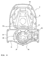
- FIG. 4 is a transverse sectional view taken along the line IV-IV in FIG. 1 according to the embodiment.
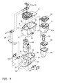
- FIG. 5 is an exploded perspective view showing an upper casing and its surrounding members of the outboard motor according to the embodiment.
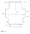
- FIG. 6 is a front view showing the upper casing of the outboard motor according to the embodiment.
- FIG. 2 shows a state that a side cover 15, which will be described later, is removed.
- a lower casing 3 is provided below an upper casing 2, and an engine 5 is mounted above the upper casing 2 via a generally flat mounting plate 4.
- the engine 5 is, for example, a water-cooled V6 engine and is mounted on the mounting plate 4 in a manner that a crankshaft 6 thereof is in a vertical position.
- the engine 5 is covered by a detachable upper cover 13 and a detachable lower cover 14. As shown in FIG. 3 , a right side surface and a left side surface of the upper casing 2 are covered by a side cover 15, which is also detachable.
- the upper casing 2 is divided by dividers 2g, 2h into a front chamber and a rear chamber (the front and rear in a traveling direction of a watercraft indicated by the arrow in FIG. 1 ).
- a front chamber 2i forward chamber is a space in which a drive shaft 18, a transmission 26, and the like are disposed.
- a rear chamber 2j (rearward chamber) is a space to dispose therein an oil pan 51 for housing lubricating oil, an oil pan cover 52 to lid the oil pan 51, an exhaust pipe 53 that is mounted to communicate with an exhaust hole 51 a formed in the oil pan 51 and that lets exhaust gases discharged from the engine pass through, an exhaust expansion chamber 54 for expanding the exhaust gases passed through the exhaust pipe 53, an exhaust chamber cover 55 disposed between the exhaust expansion chamber 54 and the exhaust pipe 53, and the like.
- the engine is lubricated with the oil housed in the oil pan 51.
- the exhaust gases discharged from the engine flow to an exhaust passage 23, which will be described later, through the exhaust pipe 53 and the expansion chamber 54, and is discharged in the water.
- the dividers 2g, 2h of the upper casing 2 are formed in a structure with material and thickness to prevent influences of the rear chamber 2j, which can reach a high temperature, from affecting the front chamber 2i.
- the vertical drive shaft 18 is pivotally supported in the front chamber 2i of the upper casing 2.
- the upper end of the drive shaft 18 is coupled to the lower end of the crankshaft 6 of the engine 5 by spline-fitting.
- the drive shaft 18 extends downward in the upper casing 2, reaches the inside of the lower casing 3, and links to a propeller shaft 20 pivotally supported in the lower casing 3 in a horizontal manner via a bevel gear mechanism 19.
- the transmission 26 is provided in the front chamber 2i of the upper casing 2.
- the transmission 26 is mounted on the drive shaft 18 and is constituted to house a speed-changing planetary gear mechanism 28 and a forward/reverse switch 29 in a transmission case 27 that makes up an outer shell of the transmission 26.
- a final deceleration device 30 that utilizes a planetary gear mechanism is provided right under the transmission 26.
- the propeller shaft 20 is a double-rotary shaft that coaxially combines an outer shaft 20a with an inner shaft 20b.
- a drive bevel gear 19a of the bevel gear mechanism 19 rotates as a unit with the drive shaft 18, a driven bevel gear 19b thereof rotates as a unit with the outer shaft 20a, and a driven bevel gear 19c thereof rotates as a unit with an inner shaft 20b.
- a first propeller 21 a is fixed to the outer shaft 20a.
- a second propeller 21 b is fixed to the inner shaft 20b.
- These members constructs a counter-rotating propeller mechanism 22.
- An exhaust path 23 is formed in the axial part of the first propeller 21 a and the second propeller 21 b.
- a water pump 41 to draw cooling water for the engine 5 is disposed on an outer surface of the upper casing 2, for example, on a right side surface thereof in the traveling direction of the watercraft.
- An elevation at which the water pump 41 is disposed is above the transmission device 26, and this position is sufficiently higher than the waterline WL (see FIG. 1 ) in operation of the outboard motor 1.
- the rotation of the crankshaft 6 is transmitted to the drive shaft 18, and the rotation of the drive shaft 18 is changed its speed and switched to the forward/reverse direction in the transmission 26. Furthermore, the rotation of the drive shaft 18 is decelerated by the final deceleration device 30 and is transmitted to the propeller shaft 20.
- the outer shaft 20a and the first propeller 21 a, and the inner shaft 20b and the second propeller 21 b of the propeller shaft 20 rotate in directions opposite to each other, thereby generating large propulsive force.
- the upper casing 2 has an upper-side casing 2a and a lower-side casing 2b, and adopts a horizontally split construction in which the upper-side casing 2a and the lower-side casing 2b are engaged with each other on a mating surface 2c located generally in a midsection of the upper casing 2 in the vertical direction and are fastened by a plurality of fixing bolts 9.
- the mounting plate 4 is fixed to a top surface of the upper-side casing 2a with a plurality of fixing bolts 10 and through bolts 11, and the lower casing 3 is fixed to a bottom surface of the lower-side casing 2b with fixing bolts, which are not shown.
- the through bolts 11 are inserted from below an upper flange of the upper-side casing 2a, pass through the mounting plate 4, and are tightened to the engine 5 so as to jointly fasten the three members 2a, 4, 5.
- the upper-side casing 2a has the upper-side divider 2g (the divider of the upper-side casing) that divides the inside of the upper-side casing 2a into the front chamber 2i and the rear chamber 2j.
- the lower-side casing 2b has a lower-side divider 2h (the divider of the lower-side casing) that divides the inside of the lower-side casing 2b into the front chamber 2i and the rear chamber 2j.
- the upper-side divider 2g and the lower-side divider 2h are configured to be coplanar with and joined to each other in a position where the upper-side casing 2a engages with the lower-side casing 2b on the mating surface 2c. In this way, the front chamber 2i and the rear chamber 2j of the upper casing 2 are separated (divided) from each other.
- a plurality of upper-side bolt seats (bolt seats) for joining is formed on a mating surface portion 2f of the upper-side divider 2g.
- a plurality of lower-side bolt seats (bolt seats) 2m for joining is formed in positions corresponding to the upper-side bolt seats of the upper-side divider 2g in the mating surface portion 2f.
- the upper-side bolt seats of the upper-side divider 2g are positioned with the lower-side bolt seats 2m of the lower-side divider 2h, and bolts are inserted in the seats to join the joined surfaces (mating surfaces) 2c of the dividers 2g, 2h.
- the joined surfaces (mating surfaces) 2c of the upper-side and the lower-side divider 2g, 2h are further rigidly joined and sealed so as to reliably separate (divide) the front chamber 2i from the rear chamber 2j of the upper casing 2.
- an upper section 2d of the upper casing 2 that is, the lateral width of the upper section 2d of the upper-side casing 2a (the width in the right and left direction of FIGs. 3 and 6 ) is arranged narrow (thin) in accordance with a joined surface of the mounting plate 4, which is to be joined.
- a lower section 2e of the upper casing 2 that is, the lateral width of the lower section 2e of the lower-side casing 2b (the width in the right and left direction of FIGs. 3 and 6 ) is arranged narrow (thin) in accordance with a joined surface of the lower casing 3, which is to be joined.
- the mating surface portion 2f that holds the mating surface 2c of the upper casing 2 therebetween that is, the lateral widths of the front chamber 2i in a portion lower than the upper section 2d of the upper-side casing 2a and in a portion higher than the lower section 2e of the lower-side casing 2b (lateral widths in FIGs. 3 and 6 ) are arranged wider than the upper section 2d and the lower section 2e in accordance with the size and configuration of the transmission 26, which is disposed in the front chamber 2i.
- the upper casing 2 is constituted by the upper-side casing 2a and the lower-side casing 2b which hold the mating surface 2c therebetween. Therefore, during assembly of the outboard motor 1, the transmission 26 can be inserted from the mating surface 2c and disposed in the front chamber 2i of the upper casing 2.
- a lateral width of the transmission 26 to be disposed is larger than the lateral width of the joined surface between the mounting plate 4 and the upper section 2d of the upper casing 2 and also larger than the lateral width of the joined surface between the lower casing 3 and the lower section 2e of the upper casing 2, the transmission 26 cannot be inserted in an upper casing of a conventional single unit type. Consequently, at least either one of the upper section or the lower section of the upper casing has to be configured larger in the lateral width so that the transmission 26 can be inserted in the upper casing.
- the mounting plate or the lower case that joins to the upper section or the lower section of the upper case need to be remade to fit the upper casing, and contribute partly to the increased cost for assembly of the outboard motor having the transmission.
- the upper casing 2 is constituted by the upper-side casing 2a and the lower-side casing 2b, which hold the mating surface 2c therebetween. Therefore, even when the lateral widths of the upper section 2d and the lower section 2e of the upper casing are narrow, the transmission 26 can be inserted from the mating surface 2c in the widely-configured mating surface portion 2f. Accordingly, the transmission 26 can be inserted in the upper casing 2 without any modification to the joined surface of the upper section 2d with the lower section 2e.
- the assembly of the outboard motor 1 having the transmission 26 as long as the upper casing 2 is configured in a manner that the upper section 2d and the lower section 2e are respectively formed to fit the mounting plate 4 and the lower casing 3 of the current condition and that the mating surface portion 2f is formed to fit the transmission 26 to be disposed, the assembly can be performed without making any modifications to the other components. As a result, it is possible to hold down the cost for the assembly of the outboard motor 1. In addition, since there is no need to extend the lateral width from the lower section 2e of the upper casing 2 through the lower casing 3, it is possible to prevent an increase in resistance to water.
- a steering bracket 39 is fixedly coupled to a front section of the outboard motor 1 via a right and left pair of upper mounts 33, which is installed in the mounting plate 4 and placed to hold the drive shaft 18 therebetween, and via a right and left pair of lower mounts 34 provided on right and left side surfaces of the lower-side casing 2b of the upper casing 2.
- the steering bracket 39 is coupled to a swivel bracket 36 by a vertical steering shaft 35, which is shown in FIG. 1 .
- the swivel bracket 36 is coupled to a clamp bracket 38 via a horizontal tilt shaft 37 and a lock mechanism, which is not shown.
- the clamp bracket 38 is fixed to a transom of a hull S of a boat.
- the outboard motor 1 can steer the hull S by pivoting to the right and the left about the steering shaft 35, and can also be tilted up above the water surface by pivoting vertically about the tilt shaft 37.
- the right and left pair of upper mounts 33 and the right and left pair of lower mounts 34 in this embodiment support the weight of the outboard motor 1, and increase a spring constant by increasing hardness of elastic members such as rubber disposed in the upper mounts 33 and the lower mounts 34 so that the propulsive force obtained by the outboard motor 1 can easily be transmitted to the hull S.
- the right and left pair of upper mounts 33 in the present embodiment is disposed with a short distance therebetween, thereby absorbing the rotational vibration by lowering the spring constant in a rotational direction.
- a width between the lower mounts 34 is wider than the width between the upper mounts 33.
- the right and left pair of upper mounts 33 is disposed in a manner that the lateral width thereof (a distance between outer ends of the two upper mounts 33) becomes narrower than the lateral width of the mating surface portion 2f of the upper casing 2 from which the transmission 26 is disposed.
- the above constitution cannot be realized in the upper casing of a single unit type to which the transmission is inserted from above, and can only be achieved with the outboard motor 1 of the present teaching adopting the constitution in which the transmission 26 is inserted from the mating surface 2c of the upper-side casing 2a with the lower-side casing 2b.
- the upper casing 2 is constituted by the upper-side casing 2a and the lower-side casing 2b.
- the mating surface portion 2f between the upper-side casing 2a and the lower-side casing 2b is larger in the lateral width than the upper section 2d and the lower section 2e of the upper casing 2. Therefore, the transmission 26 can be inserted from the mating surface 2c between the upper-side casing 2a and the lower-side casing 2b and disposed in the front chamber 2i of the upper casing 2.
- a distance between the upper mounts 33, which are provided as the right and left pair to support the outboard motor 1 to the hull S, is narrower than the lateral width of the mating surface portion 2f in the upper casing 2. Therefore, the upper mounts 33 can suppress the vibration of the hull S by absorbing the rotational vibration of the outboard motor 1.
- the dividers 2g, 2h are provided in a manner that the upper-side divider (the divider of the upper-side casing) 2g and the lower-side divider (the divider of the lower-side casing) 2h are joined to each other to divide the inside of the upper casing 2 into the front chamber 2i and the rear chamber 2j.
- the transmission 26 is disposed in the front chamber 2i.
- the transmission 26 can easily be placed in a given position in the upper casing 2 and can be prevented from the influences of the components disposed in the rear chamber 2j (heat, oil content, and moisture, for example).
- the upper-side bolt seat (bolt seat) and the lower-side bolt seat (bolt seat) 2m for joining are formed in the mating surface portions 2f of the dividers 2g, 2h.
- the mating surfaces (joined surfaces) 2c of the dividers 2g, 2h are sealed.
- the transmission 26 disposed in the upper casing 2 is not limited to one described in this embodiment.
- a transmission with large width or one in a different configuration may be disposed.
- the upper casing 2 may be prepared with the mating surface portion 2f that is wider in the lateral width or in a configuration to fit the transmission 26.
- the position of the mating surface 2c between the upper-side casing 2a and the lower-side casing 2b in the vertical direction is generally in the midsection of the upper casing 2 in the vertical direction.
- the position of the mating surface C is not limited to the above.
- a position deviated upward in the upper casing 2 may be set as the mating surface 2c, or a position deviated downward in the upper casing 2 may be set as the mating surface 2c.
- an outboard motor constituted in which a lower casing is provided below an upper casing, an engine with a vertically-arranged crankshaft is mounted above the upper casing, and rotation of the crankshaft is transmitted to a drive shaft pivotally supported in the upper casing, is changed its speed in a transmission mounted on the drive shaft, and is transmitted to a propeller shaft pivotally supported in the lower casing, wherein the upper casing is constituted by an upper-side casing and a lower-side casing, and a mating surface portion between the upper-side casing and the lower-side casing is laterally wider than an upper section and a lower section of the upper casing.
- an upper mount and a lower mount are included to support the outboard motor to a hull, the upper mounts are provided as a right and left pair, and width between the upper mounts is narrower than the lateral width of the mating surface portion in the upper casing.
- a divider is provided to divide the inside of the upper casing into a front chamber and a rear chamber, and the divider is formed by joining a divider of the upper-side casing to a divider of the lower-side casing.
- a bolt seat for joining is provided in the mating surface portion of the divider, and a joined surface of the divider is sealed.
- a lower casing 3 is provided below an upper casing 2
- an engine 5 with a vertically-arranged crankshaft 6 is mounted above the upper casing.
- the rotation of the crankshaft is transmitted to a drive shaft 18 pivotally supported in the upper casing, is changed its speed in a transmission 26 mounted on the drive shaft, and is transmitted to a propeller shaft 20 pivotally supported in the lower casing.
- the upper casing is constituted by an upper-side casing 2a and a lower-side casing 2b, and is characterized by that mating surface portions 2f of the upper-side casing and the lower-side casing are laterally wider than an upper section 2d and a lower section 2e of the upper casing.
Landscapes
- Chemical & Material Sciences (AREA)
- Engineering & Computer Science (AREA)
- Combustion & Propulsion (AREA)
- Mechanical Engineering (AREA)
- Ocean & Marine Engineering (AREA)
- General Details Of Gearings (AREA)
- Exhaust Silencers (AREA)
Applications Claiming Priority (1)
| Application Number | Priority Date | Filing Date | Title |
|---|---|---|---|
| JP2007340004A JP2009160969A (ja) | 2007-12-28 | 2007-12-28 | 船外機 |
Publications (2)
| Publication Number | Publication Date |
|---|---|
| EP2075191A2 true EP2075191A2 (de) | 2009-07-01 |
| EP2075191A3 EP2075191A3 (de) | 2009-07-15 |
Family
ID=40566239
Family Applications (1)
| Application Number | Title | Priority Date | Filing Date |
|---|---|---|---|
| EP08022400A Withdrawn EP2075191A3 (de) | 2007-12-28 | 2008-12-23 | Aussenbordmotor |
Country Status (3)
| Country | Link |
|---|---|
| US (1) | US7934964B2 (de) |
| EP (1) | EP2075191A3 (de) |
| JP (1) | JP2009160969A (de) |
Families Citing this family (6)
| Publication number | Priority date | Publication date | Assignee | Title |
|---|---|---|---|---|
| EP2489868B1 (de) * | 2011-02-17 | 2015-01-14 | Suzuki Motor Corporation | Außenbordmotor |
| US9133910B1 (en) | 2013-03-15 | 2015-09-15 | Brunswick Corporation | Marine transmission with synchronizer to shift into high speed gear |
| US9718529B2 (en) | 2013-03-15 | 2017-08-01 | Brunswick Corporation | Transmission for marine propulsion |
| JP6156106B2 (ja) * | 2013-12-03 | 2017-07-05 | スズキ株式会社 | 船外機 |
| JP6597255B2 (ja) * | 2015-12-08 | 2019-10-30 | スズキ株式会社 | 船外機の遠隔操舵機構 |
| EP3590821B1 (de) * | 2018-07-05 | 2021-02-24 | OXE Marine AB | Aussenbordmotor |
Citations (1)
| Publication number | Priority date | Publication date | Assignee | Title |
|---|---|---|---|---|
| WO2007007707A1 (ja) | 2005-07-14 | 2007-01-18 | Yamaha Marine Kabushiki Kaisha | 船外機 |
Family Cites Families (6)
| Publication number | Priority date | Publication date | Assignee | Title |
|---|---|---|---|---|
| JPS62191297A (ja) * | 1986-02-17 | 1987-08-21 | Honda Motor Co Ltd | 船外機 |
| JP3881790B2 (ja) * | 1998-09-28 | 2007-02-14 | 本田技研工業株式会社 | 船外機における冷却装置 |
| JP2001213395A (ja) | 2000-02-07 | 2001-08-07 | Honda Motor Co Ltd | 船外機 |
| US7244152B1 (en) * | 2006-02-09 | 2007-07-17 | Brunswick Corporation | Support system for an outboard motor |
| JP4608460B2 (ja) * | 2006-05-25 | 2011-01-12 | 本田技研工業株式会社 | 船外機 |
| US7494392B1 (en) * | 2007-01-12 | 2009-02-24 | Latham Robert P | Outboard motor shaft support |
-
2007
- 2007-12-28 JP JP2007340004A patent/JP2009160969A/ja active Pending
-
2008
- 2008-12-22 US US12/340,822 patent/US7934964B2/en active Active
- 2008-12-23 EP EP08022400A patent/EP2075191A3/de not_active Withdrawn
Patent Citations (1)
| Publication number | Priority date | Publication date | Assignee | Title |
|---|---|---|---|---|
| WO2007007707A1 (ja) | 2005-07-14 | 2007-01-18 | Yamaha Marine Kabushiki Kaisha | 船外機 |
Also Published As
| Publication number | Publication date |
|---|---|
| US7934964B2 (en) | 2011-05-03 |
| JP2009160969A (ja) | 2009-07-23 |
| EP2075191A3 (de) | 2009-07-15 |
| US20090170386A1 (en) | 2009-07-02 |
Similar Documents
| Publication | Publication Date | Title |
|---|---|---|
| EP2075191A2 (de) | Aussenbordmotor | |
| EP2075192B1 (de) | Aussenbordmotor | |
| JP2023044489A (ja) | ハイブリッド船舶推進機 | |
| US8142244B2 (en) | Outboard motor | |
| EP3786054A1 (de) | Aussenbordmotor | |
| US5820425A (en) | Outboard drive lower unit | |
| EP3168135B1 (de) | Aussenbordmotor | |
| US9868500B1 (en) | Outboard motor | |
| JP2024157675A (ja) | 船外機および船舶 | |
| US20240208628A1 (en) | Outboard motor | |
| JP4416642B2 (ja) | 船外機 | |
| JP2019123271A (ja) | 船外機および船外機のシフト切替装置 | |
| EP4454994A1 (de) | Aussenbordmotor und boot | |
| EP4390077B1 (de) | Aussenbordmotor | |
| US20240359783A1 (en) | Outboard motor and boat | |
| JP2023044488A (ja) | ハイブリッド船舶推進機 | |
| EP4566937A1 (de) | Aussenbordmotor und boot | |
| US11767094B2 (en) | Outboard motor | |
| US12384502B2 (en) | Outboard motor and boat | |
| EP4454993A1 (de) | Aussenbordmotor und boot | |
| US20240343371A1 (en) | Outboard motor and boat | |
| US20230318395A1 (en) | Outboard engine | |
| EP4563459A1 (de) | Aussenbordmotor und boot | |
| JP2026052166A (ja) | 船舶推進機および船舶 | |
| JP2012017033A (ja) | 船外機のマウント装置 |
Legal Events
| Date | Code | Title | Description |
|---|---|---|---|
| PUAI | Public reference made under article 153(3) epc to a published international application that has entered the european phase |
Free format text: ORIGINAL CODE: 0009012 |
|
| PUAL | Search report despatched |
Free format text: ORIGINAL CODE: 0009013 |
|
| AK | Designated contracting states |
Kind code of ref document: A2 Designated state(s): AT BE BG CH CY CZ DE DK EE ES FI FR GB GR HR HU IE IS IT LI LT LU LV MC MT NL NO PL PT RO SE SI SK TR |
|
| AX | Request for extension of the european patent |
Extension state: AL BA MK RS |
|
| AK | Designated contracting states |
Kind code of ref document: A3 Designated state(s): AT BE BG CH CY CZ DE DK EE ES FI FR GB GR HR HU IE IS IT LI LT LU LV MC MT NL NO PL PT RO SE SI SK TR |
|
| AX | Request for extension of the european patent |
Extension state: AL BA MK RS |
|
| AKX | Designation fees paid | ||
| STAA | Information on the status of an ep patent application or granted ep patent |
Free format text: STATUS: THE APPLICATION IS DEEMED TO BE WITHDRAWN |
|
| 18D | Application deemed to be withdrawn |
Effective date: 20100116 |
|
| REG | Reference to a national code |
Ref country code: DE Ref legal event code: 8566 |