EP4454993A1 - Aussenbordmotor und boot - Google Patents
Aussenbordmotor und boot Download PDFInfo
- Publication number
- EP4454993A1 EP4454993A1 EP24153178.9A EP24153178A EP4454993A1 EP 4454993 A1 EP4454993 A1 EP 4454993A1 EP 24153178 A EP24153178 A EP 24153178A EP 4454993 A1 EP4454993 A1 EP 4454993A1
- Authority
- EP
- European Patent Office
- Prior art keywords
- gear
- bearing
- shaft
- case
- gear shaft
- Prior art date
- Legal status (The legal status is an assumption and is not a legal conclusion. Google has not performed a legal analysis and makes no representation as to the accuracy of the status listed.)
- Pending
Links
Images


Classifications
-
- B—PERFORMING OPERATIONS; TRANSPORTING
- B63—SHIPS OR OTHER WATERBORNE VESSELS; RELATED EQUIPMENT
- B63H—MARINE PROPULSION OR STEERING
- B63H20/00—Outboard propulsion units, e.g. outboard motors or Z-drives; Arrangements thereof on vessels
- B63H20/14—Transmission between propulsion power unit and propulsion element
-
- B—PERFORMING OPERATIONS; TRANSPORTING
- B63—SHIPS OR OTHER WATERBORNE VESSELS; RELATED EQUIPMENT
- B63H—MARINE PROPULSION OR STEERING
- B63H20/00—Outboard propulsion units, e.g. outboard motors or Z-drives; Arrangements thereof on vessels
- B63H20/32—Housings
-
- B—PERFORMING OPERATIONS; TRANSPORTING
- B63—SHIPS OR OTHER WATERBORNE VESSELS; RELATED EQUIPMENT
- B63H—MARINE PROPULSION OR STEERING
- B63H20/00—Outboard propulsion units, e.g. outboard motors or Z-drives; Arrangements thereof on vessels
- B63H20/08—Means enabling movement of the position of the propulsion element, e.g. for trim, tilt or steering; Control of trim or tilt
- B63H20/12—Means enabling steering
-
- B—PERFORMING OPERATIONS; TRANSPORTING
- B63—SHIPS OR OTHER WATERBORNE VESSELS; RELATED EQUIPMENT
- B63H—MARINE PROPULSION OR STEERING
- B63H21/00—Use of propulsion power plant or units on vessels
- B63H21/12—Use of propulsion power plant or units on vessels the vessels being motor-driven
- B63H21/17—Use of propulsion power plant or units on vessels the vessels being motor-driven by electric motor
-
- B—PERFORMING OPERATIONS; TRANSPORTING
- B63—SHIPS OR OTHER WATERBORNE VESSELS; RELATED EQUIPMENT
- B63H—MARINE PROPULSION OR STEERING
- B63H20/00—Outboard propulsion units, e.g. outboard motors or Z-drives; Arrangements thereof on vessels
- B63H20/32—Housings
- B63H2020/323—Gear cases
Definitions
- the present invention relates to an outboard motor and a boat that comprises an outboard motor.
- a boat is provided with a hull and an outboard motor mounted to a rear portion of the hull.
- the outboard motor is a device that generates thrust to propel the boat.
- the outboard motor has a drive source, a propeller, and a transmission mechanism that has a propeller shaft and transmits the drive power of the drive source to the propeller.
- an outboard motor including an electric motor having an output shaft arranged along an upper-lower direction, a gear mechanism connected to the output shaft of the electric motor, and a case having a housing chamber accommodating the gear mechanism and oil.
- the gear mechanism has two gears that rotate around a rotation shaft along an upper-lower direction and mesh with each other (hereinafter referred to as "vertical shaft rotation gears"), and the gear shaft of one of the vertical shaft rotation gears is connected to the output shaft of the electric motor (see, e.g. JP 2016-37256 A ).
- This issue is not limited to electric motors but is common to outboard motors in which a transmission mechanism with gears connected to the output shaft of an engine or other drive source is accommodated in a housing chamber of a case.
- said object is solved by an outboard motor having the features of independent claim 1. Moreover, according to the present invention said object is solved by a boat according to claim 10. Preferred embodiments are laid down in the dependent claims.
- the technology disclosed herein can be implemented in various aspects, including, e.g., an outboard motor, a boat provided with an outboard motor and a hull, among other forms.
- FIG. 1 is a perspective view schematically illustrating a configuration of a boat 10 in the first embodiment.
- FIG. 1 and other drawings described below show arrows representing each direction with respect to the position of the boat 10. More specifically, each drawing shows arrows representing the front direction (FRONT), rear direction (REAR), left direction (LEFT), right direction (RIGHT), upper direction (UPPER), and lower direction (LOWER), respectively.
- the front-rear direction, left-right direction, and upper-lower (vertical) direction (first direction) are orthogonal to each other.
- the boat 10 includes a hull 200 and an outboard motor 100.
- the boat 10 has only one outboard motor 100, but the boat 10 may have multiple outboard motors 100.
- the hull 200 is a part of the boat 10 for occupants to ride.
- the hull 200 includes a hull main body 202 including a living space 204, a pilot seat 240 installed in the living space 204, and an operating device 250 installed near the pilot seat 240.
- the operating device 250 is a device for steering the boat and includes, e.g., a steering wheel 252, a shift/throttle lever 254, a joystick 255, a monitor 256, and an input device 258.
- the hull 200 includes a partition wall 220 to partition the rear end of the living space 204 and a transom 210 positioned at the rear end of the hull 200. In the front-rear direction, a space 206 is provided between the transom 210 and the partition wall 220.
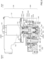
- FIG. 2 is a side view schematically illustrating a configuration of an outboard motor 100 in this embodiment.
- the outboard motor 100 in the reference attitude will be described below unless otherwise specified.
- the reference attitude is an attitude in which the rotation axis Ac of the output shaft 123 of the electric motor 122, which will be described later, extends in the (first) upper-lower direction and the rotation axis Ap of the propeller shaft 137, which will be described later, extends in the front-rear direction.
- the front-rear direction, the left-right direction, and the upper-lower direction are respectively defined based on the outboard motor 100 in the reference attitude.
- the outboard motor 100 is a device that generates thrust to propel the boat 10.
- the outboard motor 100 is attached to the transom 210 at a rear portion of the hull 200.
- the outboard motor 100 includes an outboard motor main body 110 and a suspension device 150.
- the outboard motor main body 110 includes a motor assembly 120, a transmission mechanism 130, a propeller 112, a cowl 114, a casing 116, a water pump 140, and a pump shaft 134.
- the cowl 114 is a housing located on top of the outboard motor main body 110.
- the cowl 114 includes an upper cowl 114a constituting the upper part of the cowl 114 and a lower cowl 114b constituting the lower part of the cowl 114.
- the upper cowl 114a is detachably attached to the lower cowl 114b.
- the casing 116 is a housing located below the cowl 114 and provided in the lower part of the outboard motor main body 110.
- the casing 116 includes a lower case 116b and an upper case 116a.
- the lower case 116b accommodates at least a portion of the drive shaft 133 and the propeller shaft 137 described below.
- the lower case 116b is connected to the upper case 116a so as to be pivotable around the drive shaft 133.
- the upper case 116a is located above the lower case 116b and accommodates a gearbox assembly 300 described below.
- a motor assembly 120 is accommodated within the cowl 114.
- the motor assembly 120 has an electric motor 122.
- the electric motor 122 is an example of the drive source in the claims.
- the electric motor 122 has an output shaft 123 that outputs the drive power generated by the electric motor 122.
- the transmission mechanism 130 is a mechanism that transmits the driving force of the electric motor 122 to the propeller 112. At least a portion of the transmission mechanism 130 is accommodated in the casing 116.
- the transmission mechanism 130 has a gearbox assembly 300, a drive shaft 133, and a propeller shaft 137.
- the propeller shaft 137 is a rod-shaped member and is positioned in a forward and backward extending orientation relatively below the outboard motor main body 110.
- the propeller shaft 137 rotates with the propeller 112.
- the front end of the propeller shaft 137 is accommodated in the lower case 116b, and the rear end of the propeller shaft 137 protrudes rearward from the lower case 116b.
- the front end of the propeller shaft 137 has a gear 138.
- the gearbox assembly 300 is connected to the output shaft 123 of the electric motor 122 and the drive shaft 133.
- the gearbox assembly 300 reduces the driving force of the electric motor 122 and transmits the reduced driving force to the propeller shaft 137. This allows the electric motor 122 to rotate at a desired torque.
- the configuration of the gearbox assembly 300 will be described in detail later.
- the propeller 112 is a rotor with multiple blades and is attached to the rear end of the propeller shaft 137.
- the propeller 112 rotates along with the rotation of the propeller shaft 137 around the rotation axis Ap.
- the propeller 112 generates thrust by rotating.
- the propeller 112 since the lower case 116b is pivotable, the propeller 112 pivots about the drive shaft 133 along with the lower case 116b. Therefore, the boat 10 is steered by pivoting the lower case 116b.
- the water pump 140 pumps water from outside the outboard motor 100, e.g., to cool the electric motor 122.
- the pump shaft 134 extends in an upper-lower direction.
- the pump shaft 134 is driven by the drive power of the electric motor 122 and transmits power to the water pump 140.
- the water pump 140 is driven by the driving force of the electric motor 122 transmitted by the pump shaft 134.
- the suspension device 150 is a device to suspend the outboard motor main body 110 to the hull 200.
- the suspension device 150 includes a pair of left and right clamp brackets 152, a tilt shaft 160, and a swivel bracket 156.
- the pair of left and right clamp brackets 152 are disposed behind the hull 200 in a state separated from each other in the left-right direction and are fixed to the transom 210 of the hull 200 by using, e.g., bolts.
- Each clamp bracket 152 has a cylindrical supporting portion 152a provided with a through-hole extending in the left-right direction.
- the tilt shaft 160 is a rod-shaped member and is rotatably supported within the through-hole in the supporting portion 152a of the clamp bracket 152.
- the tilt axis At which is the centerline of the tilt shaft 160, constitutes the horizontal (left-right) axis in the tilting operation of the outboard motor 100.
- the swivel bracket 156 is positioned so as to be sandwiched between the pair of clamp brackets 152 and is supported by the supporting portion 152a of the clamp brackets 152 via the tilt shaft 160 so as to be rotatable around the tilt axis At.
- the swivel bracket 156 is driven to rotate about the tilt axis At with respect to the clamp bracket 152 by a tilt device (not shown) that includes an actuator, such as a hydraulic cylinder, for example.
- the outboard motor main body 110 supported by the swivel bracket 156 also rotates about the tilt axis At. This achieves the tilting operation of rotating the outboard motor main body 110 in the upper-lower direction with respect to the hull 200.
- the outboard motor 100 can change the angle of the outboard motor main body 110 around the tilt axis At in the range from the tilt-down state in which the propeller 112 is located under the water (the state in which the outboard motor 100 is in the reference attitude) to the tilt-up state in which the propeller 112 is located above the water surface. Trimming operation for adjusting the attitude of the boat 10 during travel can also be performed by adjusting the angle around the tilt axis At of the outboard motor main body 110.
- FIG. 3 is an explanatory view schematically illustrating an internal configuration of a motor assembly 120 and a gearbox assembly 300. As shown in FIG. 3 , the motor assembly 120 and the gearbox assembly 300 are separated from each other and are each accommodated in an individual case.
- the motor assembly 120 includes the electric motor 122 as described above and a motor case 121 that supports the electric motor 122.
- the electric motor 122 is placed vertically in the motor case 121.
- Vertical placement means that the output shaft 123 (rotation axis Ac) of the electric motor 122 is arranged in an attitude in which it extends in the upper-lower direction.
- the upper and lower ends of the output shaft 123 are rotatably supported by a motor bearing 125 fixed to the motor case 121, respectively.
- the gearbox assembly 300 has a primary reduction gear mechanism 310 and a gear case 302.
- the gear case 302 is an example of the case in the claims.
- the gear case 302 has a housing chamber R1 that accommodates the primary reduction gear mechanism 310 and oil S.
- the gear case 302 has an upper gear case 302a and a lower gear case 302b combined in the upper-lower direction to form the housing chamber R1.
- the housing chamber R1 includes an input side region R11 and an output side region R12.
- the input side region R11 is the region of the housing chamber R1 that is located directly below the electric motor 122.
- the output side region R12 is a region of the housing chamber R1 that is located forward of the input side region R11.
- the gear case 302 is provided with an input through-hole H1 opening upward from the input side region R11, a through-hole H2 opening downward from the input side region R11, and an output through-hole H3 opening downward from the output side region R12.
- the primary reduction gear mechanism 310 includes an input gear 320, an upper input bearing 326, a lower input bearing 350, an output gear 330, an upper output bearing 336, and a lower output bearing 337.
- the input gear 320, the upper input bearing 326, and the lower input bearing 350 are accommodated in the input side region R11 of the gear case 302.
- the output gear 330, the upper output bearing 336, and the lower output bearing 337 are accommodated in the output side region R12 of the gear case 302.
- the input gear 320 has an input gear shaft 324 along the upper-lower direction, and the upper end of the input gear shaft 324 is connected to the output shaft 123 of the electric motor 122.
- the input gear 320 is a helical gear.
- the input gear 320 is an example of the first helical gear in the claims
- the input gear shaft 324 is an example of the first gear shaft in the claims.
- the input gear 320 includes an input gear shaft 324 and an input gear body 322 fixed to the input gear shaft 324.
- the input gear body 322 and the input gear shaft 324 may be separated from each other or may be integrally formed.
- the input gear shaft 324 is arranged in an attitude in which it extends along the upper-lower direction.
- An insertion hole 325 is formed in the upper end of the input gear shaft 324.
- the output shaft 123 of the electric motor 122 protrudes into the input side region R11 through the above-mentioned input through-hole H1 of the gear case 302 and is inserted into and fixed to the insertion hole 325 of the input gear shaft 324.
- the input gear 320 rotates integrally with the output shaft 123 around the rotation axis Ac.
- the upper input bearing 326 is located on the upper side of the input gear body 322, is fixed to the gear case 302 (upper gear case 302a), and rotatably supports the upper end of the input gear shaft 324.
- the lower input bearing 350 is located on the lower side of the input gear body 322, is fixed to the gear case 302 (lower gear case 302b), and rotatably supports the lower end of the input gear shaft 324.
- the through-hole H2 of the gear case 302 is sealed by a cap 303.
- the upper input bearing 326 is an example of the first bearing in the claims
- the lower input bearing 350 is an example of the second bearing in the claims.
- the output gear 330 has an output gear shaft 334 along the upper-lower direction and meshes with the input gear 320.
- the output gear 330 is a helical gear.
- the output gear 330 is an example of the second helical gear in the claims, and the output gear shaft 334 is an example of the second gear shaft in the claims.
- the output gear 330 has an output gear shaft 334 and an output gear body 332 fixed to the output gear shaft 334.
- the output gear body 332 and the output gear shaft 334 may be separated from each other or may be integrally formed.
- the output gear shaft 334 is arranged in an attitude in which it extends along the upper-lower direction.
- An insertion hole 345 is formed in the lower end of the output gear shaft 334.
- the drive shaft 133 protrudes into the output side region R12 through the above-mentioned output through-hole H3 of the gear case 302 and is inserted into and fixed to the insertion hole 345 of the output gear shaft 334.
- the output gear 330 rotates integrally with the drive shaft 133.
- the upper output bearing 336 is located on the upper side of the output gear body 332, is fixed to the gear case 302 (upper gear case 302a), and rotatably supports the upper end of the output gear shaft 334.
- the lower output bearing 337 is located on the lower side of the output gear body 332, is fixed to the gear case 302 (lower gear case 302b), and rotatably supports the lower end of the output gear shaft 334.
- the input gear 320 rotates by receiving driving force from the output shaft 123 of the electric motor 122.
- the output gear 330 rotates in conjunction with the input gear 320, and the drive shaft 133 rotates as the output gear 330 rotates.
- the number of teeth of the input gear 320 is greater than that of the output gear 330. Therefore, the drive shaft 133 rotates at a reduced speed relative to the rotational speed of the output shaft 123 by the ratio of the number of teeth of the input gear 320 to the number of teeth of the output gear 330 (reduction ratio).
- the primary reduction gear mechanism 310 transmits the driving force of the electric motor 122 to the drive shaft 133 while reducing the rotational speed of the electric motor 122.
- the boat 10 has a fixing mechanism 340 that fixes the input gear shaft 324 of the input gear 320 at a predetermined position in the upper-lower direction with respect to the gear case 302.
- the fixing mechanism 340 is configured by fixing the lower input bearing 350 to the gear case 302 and the lower end of the input gear shaft 324 in the upper-lower direction.
- the lower input bearing 350 is a double row angular bearing.
- the doublerow angular bearing has a structure in which the inner and outer rings are integrated by combining a pair of single-row angular bearings 352, 354 that can receive thrust loads in mutually opposite directions.
- Angular bearings are non-separating bearings, in which the straight line connecting the contact points between the balls and the inner and outer rings has a certain angle (contact angle) to the radial direction.
- the lower gear case 302b has a contact surface 323 that contacts the upper surface 356 of the lower input bearing 350.
- a protrusion that protrudes inward in the radial direction is formed all around the inner circumference of the through-hole H2, and the lower surface of this protrusion is the above contact surface 323.
- the lower end of the input gear shaft 324 has a large diameter portion 324a, a medium diameter portion 324b, and a small diameter portion 324c.
- the medium diameter portion 324b is located below the large diameter portion 324a
- the small diameter portion 324c is located below the medium diameter portion 324b.
- the outer diameter of the medium diameter portion 324b is smaller than the outer diameter of the large diameter portion 324a, and a first stepped surface D1 is formed between the medium diameter portion 324b and the large diameter portion 324a.
- the lower input bearing 350 is fitted into the medium diameter portion 324b, and the upper surface 356 of the lower input bearing 350 is in contact with the first stepped surface D1 in the upper-lower direction together with the contact surface 323 of the gear case 302.
- the outer diameter of the small diameter portion 324c of the input gear shaft 324 is smaller than the outer diameter of the medium diameter portion 324b, and a second stepped surface D2 is formed between the small diameter portion 324c and the medium diameter portion 324b.
- a washer 362 as an annular member is fitted into the small diameter portion 324c.
- the upper surface of the washer 362 is in contact with the lower surface 358 of the lower input bearing 350 in the upper-lower direction.
- the washer 362 is fixed to the input gear shaft 324 (small diameter portion 324c) by a fastening mechanism. Specifically, a male thread is formed on the outer circumference of the small diameter portion 324c, and a nut 364 is screwed onto the small diameter portion 324c.
- the washer 362 is sandwiched in the upper-lower direction between the lower surface 358 of the lower input bearing 350 and the second stepped surface D2 of the input gear shaft 324 and the upper surface of the nut 364.
- the input gear shaft 324, the gear case 302, and the lower input bearing 350 are fastened together by the fastening mechanism.
- the portion of the washer 362 protruding radially outward from the medium diameter portion 324b is an example of the protruding portion in the claims.
- the input gear shaft 324 is immovably fixed to the lower input bearing 350 in the upper-lower direction, and this lower input bearing 350 is immovably fixed to the electric motor 122 side by the contact surface 323 of the gear case 302.
- the lower input bearing 350 supporting the input gear shaft 324 is a double row angular bearing and thus absorbs thrust loads in both upper and lower directions generated on the input gear shaft 324 as the input gear 320 and output gear 330 rotate. Therefore, the fixing mechanism 340 can fix the input gear shaft 324 of the input gear 320 at a predetermined position in the upper-lower direction with respect to the gear case 302. Therefore, thrust loads are restrained from being applied to the output shaft 123 of the electric motor 122.
- the motor bearing 125 supporting, e.g., the electric motor 122 does not need to be a large bearing that can withstand a relatively large load, and an increase in the size of the motor case 121 can be suppressed.
- axes, members, and the like extending in the front-rear direction need not necessarily be parallel to the front-rear direction.
- Axes and members extending in the front-rear direction include axes and members that are inclined in the range of ⁇ 45° to the front-rear direction.
- axes and members extending in the upper-lower direction include axes and members inclined within a range of ⁇ 45° to the upper-lower direction
- axes and members extending in the left-right direction include axes and members inclined within a range of ⁇ 45° to the left-right direction.
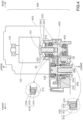
- FIG. 4 is an explanatory view schematically illustrating an internal configuration of a motor-gear integrated assembly 400 in the second embodiment.
- the description of the configuration of the boat 10 of the second embodiment which is identical to that of the boat 10 of the first embodiment described above, will be omitted as appropriate.
- This second embodiment differs from the first embodiment above in that it has a motor-gear integrated assembly 400 instead of a motor assembly 120 and a gearbox assembly 300.
- the motor-gear integrated assembly 400 includes an electric motor 122 and a primary reduction gear mechanism 405 accommodated in an integral case 402.
- the integral case 402 is an example of the case in the claims.
- the upper portion of the integral case 402 accommodates the electric motor 122 and a motor bearing 125 that supports the upper end of the output shaft 123 of the electric motor 122.
- the lower end of the output shaft 123 is supported by the first tapered roller bearing 410 described below, which is provided in the primary reduction gear mechanism 405.
- the primary reduction gear mechanism 405 is accommodated in the lower portion of the integral case 402.
- the primary reduction gear mechanism 405 differs from the primary reduction gear mechanism 310 of the first embodiment in the configuration of the bearing supporting the input gear 320.
- the primary reduction gear mechanism 405 has a first tapered roller bearing 410 and a second tapered roller bearing 420 instead of the upper input bearing 326 and the lower input bearing 350.
- the first tapered roller bearing 410 and the second tapered roller bearing 420 constitute the fixing mechanism.
- the first tapered roller bearing 410 is fixed within the input through-hole H1 of the integral case 402 and supports the upper end of the input gear shaft 324 of the input gear 320.
- the first tapered roller bearing 410 has tapered roller 412, an inner ring 414, and an outer ring 416 and is designed so that the raceways of the inner ring 414 and outer ring 416 and the apex of the tapered roller 412 intersect at a point on the centerline of the first tapered roller bearing 410 (the center axis of the input gear shaft 324).
- the second tapered roller bearing 420 is fixed in the input through-hole H1 of the integral case 402 and supports the lower end of the input gear shaft 324 of the input gear 320.
- the second tapered roller bearing 420 has the same configuration as the first tapered roller bearing 410. However, the first tapered roller bearing 410 and the second tapered roller bearing 420 are inclined such that the closer they are, the greater the distance between the rotation axis 415 of the tapered roller 412 and the input gear shaft 324.
- the first tapered roller bearing 410 and the second tapered roller bearing 420 absorb the thrust load generated on the input gear shaft 324 in the upper-lower direction while immovably supporting the input gear shaft 324 in the upper-lower direction. Therefore, the input gear shaft 324 of the input gear 320 can be fixed to the integral case 402 at a predetermined position in the upper-lower direction.
- the configuration of the boat 10 and outboard motor 100 of the preferred embodiment is only an example and is variously deformable.
- the drive shaft 133 is positioned in front of the output shaft 123, but the drive shaft 133 may be positioned behind the output shaft 123.
- an electric motor 122 with the output shaft 123 disposed along the upper-lower direction is shown as the drive source, but the drive source may be an electric motor with the output shaft 123 disposed along a direction other than the upper-lower direction (e.g., horizontal direction) or an engine such as internal combustion engine.
- a primary reduction gear mechanism 310 is illustrated as the transmission mechanism, but the transmission mechanism may be any other gear mechanism (such as a speed change mechanism).
- the gear mechanism may consist of two or more helical gears that rotate around a rotation shaft along the upper-lower direction and mesh with each other.
- the electric motor 122 is placed horizontally in the motor case 121. Horizontal placement means that the electric motor 122 is placed in an attitude in which the output shaft 123 (rotation axis Ac) of the electric motor 122 extends in the horizontal direction.
- the first and second gears are not limited to helical gears but may also be bevel gears. Furthermore, the first gear and the second gear may rotate around a rotation shaft along the horizontal direction.
- the lower input bearing 350 is a double row angular bearing, but it may be a pair of single-row angular bearings that can receive thrust loads in mutually opposite directions.
- the lower input bearing 350 may also be a deep groove bearing.
- the protruding portion of the washer 362 is illustrated as the protruding portion of the second end of the first gear shaft, but it may be, e.g., a protruding portion protruding radially outward from the outer circumference of the input gear shaft 324 and integrally formed with the input gear shaft 324.
- the fixing mechanism of the second embodiment above may have a configuration in which the first tapered roller bearing 410 and the second tapered roller bearing 420 are inclined such that the closer they are, the greater the distance between the rotation axis 415 of the tapered roller bearing 412 and the input gear shaft 324.
- a fixing mechanism 340 that fixes the input gear shaft 324 of the input gear 320 at a predetermined position in the upper-lower direction with respect to the gear case 302 or the integral case 402 is illustrated as the fixing mechanism, but the fixing mechanism may fix the output gear shaft 334 of the output gear 330 at a predetermined position in the upper-lower direction with respect to the gear case 302 or the integral case 402.
- This configuration can suppress the thrust load on the connecting member (e.g., drive shaft 133) connected to the output gear shaft 334.
- the lower case 116b is rotatably connected to the upper case 116a, but the lower case 116b does not necessarily have to be rotatable.
- the casing 116 need not have an upper case 116a and a lower case 116b but may be composed of a single member.
- the outboard motor 100 is provided with the water pump 140 as a driven device, but it may not be provided with the water pump 140 or may be provided with another driven device instead of the water pump 140.
Landscapes
- Chemical & Material Sciences (AREA)
- Engineering & Computer Science (AREA)
- Combustion & Propulsion (AREA)
- Mechanical Engineering (AREA)
- Ocean & Marine Engineering (AREA)
- General Details Of Gearings (AREA)
- Gear Transmission (AREA)
- Connection Of Motors, Electrical Generators, Mechanical Devices, And The Like (AREA)
Applications Claiming Priority (1)
| Application Number | Priority Date | Filing Date | Title |
|---|---|---|---|
| JP2023072161A JP2024157674A (ja) | 2023-04-26 | 2023-04-26 | 船外機および船舶 |
Publications (1)
| Publication Number | Publication Date |
|---|---|
| EP4454993A1 true EP4454993A1 (de) | 2024-10-30 |
Family
ID=89663329
Family Applications (1)
| Application Number | Title | Priority Date | Filing Date |
|---|---|---|---|
| EP24153178.9A Pending EP4454993A1 (de) | 2023-04-26 | 2024-01-22 | Aussenbordmotor und boot |
Country Status (3)
| Country | Link |
|---|---|
| US (1) | US20240359787A1 (de) |
| EP (1) | EP4454993A1 (de) |
| JP (1) | JP2024157674A (de) |
Citations (4)
| Publication number | Priority date | Publication date | Assignee | Title |
|---|---|---|---|---|
| US4595371A (en) * | 1983-12-30 | 1986-06-17 | Scott Heston | Power take-off system for marine engines |
| JPS6440745A (en) * | 1987-08-03 | 1989-02-13 | Kawasaki Heavy Ind Ltd | Automatic transmission for ship |
| JP2015107678A (ja) * | 2013-12-03 | 2015-06-11 | スズキ株式会社 | 船外機 |
| JP2016037256A (ja) | 2014-08-11 | 2016-03-22 | スズキ株式会社 | 電動船外機 |
Family Cites Families (11)
| Publication number | Priority date | Publication date | Assignee | Title |
|---|---|---|---|---|
| JPH0243722U (de) * | 1988-09-21 | 1990-03-26 | ||
| US6709243B1 (en) * | 2000-10-25 | 2004-03-23 | Capstone Turbine Corporation | Rotary machine with reduced axial thrust loads |
| CN101970150A (zh) * | 2008-03-13 | 2011-02-09 | Ntn株式会社 | 外圈制造方法、多排角接触轴承用外圈、多排角接触轴承及车轮用轴承装置 |
| JP5620941B2 (ja) * | 2012-04-26 | 2014-11-05 | Thk株式会社 | 垂直軸型流体発電装置の回転軸装置及び垂直軸型流体発電装置 |
| US9885282B2 (en) * | 2013-03-15 | 2018-02-06 | United Technologies Corporation | Turbofan engine bearing and gearbox arrangement |
| US9611023B2 (en) * | 2015-06-26 | 2017-04-04 | Honda Motor Co., Ltd. | Outboard motor for a watercraft and methods of use and manufacture thereof |
| US11346408B2 (en) * | 2019-04-04 | 2022-05-31 | Eaton Cummins Automated Transmission Tech., Llc | Virtual clutch temperature gauge |
| US11358697B1 (en) * | 2020-01-08 | 2022-06-14 | Brunswick Corporation | Systems and methods for rotatably supporting counter-rotating propeller shafts in a marine propulsion device |
| US20230019353A1 (en) * | 2020-01-10 | 2023-01-19 | Sandcraft Llc | Double row tapered bearing with press fit preloading elements |
| JP7447920B2 (ja) * | 2022-01-12 | 2024-03-12 | トヨタ自動車株式会社 | 車両用駆動装置 |
| CN118511017A (zh) * | 2022-03-25 | 2024-08-16 | 株式会社爱信 | 车用驱动装置 |
-
2023
- 2023-04-26 JP JP2023072161A patent/JP2024157674A/ja active Pending
-
2024
- 2024-01-22 EP EP24153178.9A patent/EP4454993A1/de active Pending
- 2024-02-12 US US18/438,607 patent/US20240359787A1/en active Pending
Patent Citations (4)
| Publication number | Priority date | Publication date | Assignee | Title |
|---|---|---|---|---|
| US4595371A (en) * | 1983-12-30 | 1986-06-17 | Scott Heston | Power take-off system for marine engines |
| JPS6440745A (en) * | 1987-08-03 | 1989-02-13 | Kawasaki Heavy Ind Ltd | Automatic transmission for ship |
| JP2015107678A (ja) * | 2013-12-03 | 2015-06-11 | スズキ株式会社 | 船外機 |
| JP2016037256A (ja) | 2014-08-11 | 2016-03-22 | スズキ株式会社 | 電動船外機 |
Also Published As
| Publication number | Publication date |
|---|---|
| JP2024157674A (ja) | 2024-11-08 |
| US20240359787A1 (en) | 2024-10-31 |
Similar Documents
| Publication | Publication Date | Title |
|---|---|---|
| US6702631B2 (en) | Transmission for driving, counter-rotating propellers, lubrication system, and associated methods | |
| EP1792826B1 (de) | Mittel zur Lagerung eines Antriebssystems und Antriebssystem für ein Wasserfahrzeug | |
| EP4454993A1 (de) | Aussenbordmotor und boot | |
| US8821335B2 (en) | Vessel propulsion apparatus | |
| US7934964B2 (en) | Outboard motor | |
| US5890938A (en) | Marine counter-rotational propulsion system | |
| US11459079B2 (en) | Ship propulsion machine | |
| EP4454992A1 (de) | Aussenbordmotor und boot | |
| US8926466B2 (en) | Vessel propulsion apparatus | |
| EP4454995A1 (de) | Aussenbordmotor und boot | |
| US12145705B2 (en) | Outboard motor | |
| US20240208628A1 (en) | Outboard motor | |
| US20260070640A1 (en) | Boat propulsion device and boat | |
| JP7797861B2 (ja) | 船外機 | |
| US20260054812A1 (en) | Outboard motor | |
| US12384502B2 (en) | Outboard motor and boat | |
| US20240208630A1 (en) | Outboard motor | |
| JP6757630B2 (ja) | インホイールモータ駆動装置 | |
| US20240343371A1 (en) | Outboard motor and boat | |
| JP2026052166A (ja) | 船舶推進機および船舶 | |
| JP2025141494A (ja) | 水上移動体用推進装置 | |
| KR20260045540A (ko) | 선박용 추진 장치 및 선박용 추진 장치의 설치 방법 |
Legal Events
| Date | Code | Title | Description |
|---|---|---|---|
| PUAI | Public reference made under article 153(3) epc to a published international application that has entered the european phase |
Free format text: ORIGINAL CODE: 0009012 |
|
| STAA | Information on the status of an ep patent application or granted ep patent |
Free format text: STATUS: THE APPLICATION HAS BEEN PUBLISHED |
|
| AK | Designated contracting states |
Kind code of ref document: A1 Designated state(s): AL AT BE BG CH CY CZ DE DK EE ES FI FR GB GR HR HU IE IS IT LI LT LU LV MC ME MK MT NL NO PL PT RO RS SE SI SK SM TR |
|
| P01 | Opt-out of the competence of the unified patent court (upc) registered |
Free format text: CASE NUMBER: APP_64550/2024 Effective date: 20241205 |
|
| STAA | Information on the status of an ep patent application or granted ep patent |
Free format text: STATUS: REQUEST FOR EXAMINATION WAS MADE |
|
| 17P | Request for examination filed |
Effective date: 20250425 |