EP2072829B2 - Pompe submersible - Google Patents
Pompe submersible Download PDFInfo
- Publication number
- EP2072829B2 EP2072829B2 EP07024940.4A EP07024940A EP2072829B2 EP 2072829 B2 EP2072829 B2 EP 2072829B2 EP 07024940 A EP07024940 A EP 07024940A EP 2072829 B2 EP2072829 B2 EP 2072829B2
- Authority
- EP
- European Patent Office
- Prior art keywords
- pump
- housing
- sensor
- sensor housing
- motor
- Prior art date
- Legal status (The legal status is an assumption and is not a legal conclusion. Google has not performed a legal analysis and makes no representation as to the accuracy of the status listed.)
- Not-in-force
Links
Images


Classifications
-
- F—MECHANICAL ENGINEERING; LIGHTING; HEATING; WEAPONS; BLASTING
- F04—POSITIVE - DISPLACEMENT MACHINES FOR LIQUIDS; PUMPS FOR LIQUIDS OR ELASTIC FLUIDS
- F04D—NON-POSITIVE-DISPLACEMENT PUMPS
- F04D13/00—Pumping installations or systems
- F04D13/02—Units comprising pumps and their driving means
- F04D13/06—Units comprising pumps and their driving means the pump being electrically driven
- F04D13/08—Units comprising pumps and their driving means the pump being electrically driven for submerged use
- F04D13/10—Units comprising pumps and their driving means the pump being electrically driven for submerged use adapted for use in mining bore holes
-
- E—FIXED CONSTRUCTIONS
- E21—EARTH OR ROCK DRILLING; MINING
- E21B—EARTH OR ROCK DRILLING; OBTAINING OIL, GAS, WATER, SOLUBLE OR MELTABLE MATERIALS OR A SLURRY OF MINERALS FROM WELLS
- E21B43/00—Methods or apparatus for obtaining oil, gas, water, soluble or meltable materials or a slurry of minerals from wells
- E21B43/12—Methods or apparatus for controlling the flow of the obtained fluid to or in wells
- E21B43/121—Lifting well fluids
- E21B43/128—Adaptation of pump systems with down-hole electric drives
-
- E—FIXED CONSTRUCTIONS
- E21—EARTH OR ROCK DRILLING; MINING
- E21B—EARTH OR ROCK DRILLING; OBTAINING OIL, GAS, WATER, SOLUBLE OR MELTABLE MATERIALS OR A SLURRY OF MINERALS FROM WELLS
- E21B47/00—Survey of boreholes or wells
- E21B47/008—Monitoring of down-hole pump systems, e.g. for the detection of "pumped-off" conditions
-
- F—MECHANICAL ENGINEERING; LIGHTING; HEATING; WEAPONS; BLASTING
- F04—POSITIVE - DISPLACEMENT MACHINES FOR LIQUIDS; PUMPS FOR LIQUIDS OR ELASTIC FLUIDS
- F04D—NON-POSITIVE-DISPLACEMENT PUMPS
- F04D13/00—Pumping installations or systems
- F04D13/02—Units comprising pumps and their driving means
- F04D13/06—Units comprising pumps and their driving means the pump being electrically driven
- F04D13/08—Units comprising pumps and their driving means the pump being electrically driven for submerged use
Definitions
- the invention relates to a borehole pump according to the features specified in the preamble of claim 1.
- the invention has the object, a generic borehole pump in such a way that one or more sensors can be arranged inexpensively at a suitable location and corresponding signal or data connected.
- the borehole pump according to the invention has an electric drive motor and a single-stage or multi-stage centrifugal pump driven by it.
- one or more sensors of the pump are arranged in a sensor housing, which, liquid flows through and liquid surrounds.
- the sensor housing is located between the motor and the pump, at the end of the pump or inside the pump.
- the sensor housing can either be arranged as a separate housing at the end of the pump or form part of the pump housing, so be formed integrally with this.
- the basic idea of the present invention is, if possible, to accommodate the complete sensor system, but at least one or more sensors in a separate sensor housing, which at the end the pump, within the pump or between the motor and the pump, that is arranged at the other end of the pump.
- This sensor housing may have a modular design, so that it can optionally be retrofitted to existing pumps or at least pumps of the same series can be equipped with or without sensor housing, so can be shipped with and without sensors. Since the sensor housing is arranged between the motor and pump, within the pump or at the end of the pump, the borehole pump is thereby not changed in its outer contour, but only in their length, which is particularly important for borehole pumps.
- the sensor housing according to the invention is designed and arranged in such a way that liquid flows through it and liquid is surrounded on the one hand. For example, temperatures and / or pressure can be detected by both the surrounding and the delivered fluid. Since, if possible, the entire sensor system or at least a large part is arranged inside the sensor housing, only that sensor housing needs to be provided with an outwardly directed cable, which is an advantage in borehole pumps when the sensor housing is arranged at the upper end of the pump on which anyway only the power cable runs next to the conveyor line. In the arrangement between the motor and pump, there is the advantage that the wiring can be done via the motor, which anyway requires a cable to the outside to the electrical power supply and possibly also to the control electronics.
- the sensor housing is divided into a liquid-conducting housing part and a liquid-free housing part, which are separated by a preferably formed by stainless steel sheet housing wall.
- a housing wall may be formed in the manner of a split tube comparatively thin but absolutely liquid-tight, so that, with the exception of the pressure and / or differential pressure sensors, if necessary, it is also possible to measure through the housing wall, for example temperature, vibration and the like.
- the entire flow of the pump is passed through the liquid-carrying housing part, wherein the housing part is formed so that it is almost a further pump stage or a pipe extension, that provides as little flow resistance.
- the sensors located in the sensor housing and possibly electronics requires comparatively little space, so that a small circumferential free space is usually sufficient to accommodate these components.
- the electrical energy required to operate the sensors arranged in the sensor housing and, if necessary, reprocess the electrical signals emanating therefrom, process them and convert them into digital data can be generated directly within the sensor housing in order to be present completely dispense with a line for powering the sensor housing.
- an induction arrangement is provided in the sensor housing, with which electrical energy is generated during operation of the pump.
- the induction arrangement has at least one magnet rotatably arranged in the liquid-conducting housing part and at least one arranged in the liquid-free housing part induction coil, such that a current in the coil is induced by the magnet moving past the coil, which is usable for the aforementioned purposes .
- two or more magnets are arranged, which cooperate with possibly a plurality of induction coils and thus form a kind of electrical generator.
- a drive for the magnets In order to form a drive for the magnets is provided according to a development of the invention, rotatably support a pump impeller within the liquid-conducting housing part and to be arranged so that it is rotated by the flow rate of the pump in rotation.
- the sensor housing is quasi designed as a further passive pump stage, the flow passing through it drives the impeller mounted thereon with the magnets attached thereto, thereby inducing a voltage in the one or more coils or generate a current and thus the sensor within the housing Supply electricity.
- such a passive pump impeller which is arranged freely rotatable within the sensor housing, and on which at least one magnet is arranged, also form part of a flow meter, wherein then within the liquid-free housing part, an inductive pickup, such as a coil is arranged , so that the speed of the pump impeller can be detected and above the flow rate can be determined.
- an inductive pickup such as a coil is arranged , so that the speed of the pump impeller can be detected and above the flow rate can be determined.
- It does not necessarily have a pump impeller rotatably arranged, it can be arranged rotatably a kind of wing, at the end of a magnet sits, which rotates faster or slower depending on the flow rate.
- the pump can be structurally adapted thereto, then instead of a passive impeller advantageously the drive shaft can be extended into the sensor housing inside and there are provided with a holder, which or the Magnets and is rotated by the drive shaft itself, also an active pump impeller may be provided which carries magnets.
- any desired pump stage can be designed as a sensor housing by appropriate modification. So it is also conceivable, not just one, but to provide a plurality of sensor housing to monitor, for example, the pressure of each pump stage.
- the motor is anyway an electrical supply cable, this can be used by appropriate design in a simple manner for data transmission, either by modulating the signal or by providing a further conductor. It is then expedient to transmit the electrical signals of the sensors or the data derived therefrom from the sensor housing into the motor housing.
- This is done according to the invention mechanically via the common shaft.
- an electroacoustic transducer can be provided, which converts the electrical signal into a sound signal, typically an ultrasonic signal, and transmits it directly or indirectly to the shaft.
- an acoustoelectric transducer is then provided, which converts this signal back into an electrical signal, which is then led out in a suitable manner.
- sensors may be arranged, typically one or more temperature sensors for detecting the temperature of the flow and / or the surrounding medium, a vibration sensor for detecting mechanical vibrations, a pressure or differential pressure sensor for detecting the ambient pressure and / or the delivery pressure. This list is only an example and can be supplemented by any other sensors.
- At least the sensors which need not necessarily be in communication with the surrounding or conveyed liquid, such.
- Fig. 1 illustrated well pump 1 is lowered in a borehole 2. It consists of a lower engine part 3, of which in Fig. 1 only the motor housing is visible, this is followed up to a multi-stage centrifugal pump 4, the pump stages in Fig. 1 are indicated. Between engine 3 and pump 4 there are suction openings 5 through which the liquid located in the borehole 2 is sucked, conveyed upwards by the multistage centrifugal pump 4 and finally conveyed via a pressure line 6 to the point of consumption.
- the motor 3 is supplied via a cable 7, which is guided long in the area of the centrifugal pump 4 on the outside and next to the pressure line 6 extends to a supply and control housing 8, via which the motor is supplied with power.
- a frequency converter may be provided, as well as all means for controlling and monitoring the pump.
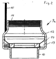
- a sensor housing 9 is arranged, the structure of which is explained below by way of example.
- sensor housing 9a is constructed rotationally symmetrical, adapted in the outer periphery to the outer periphery of the pump stages and has on its underside a threaded connector 10 which is provided for incorporation into the end-side thread of the centrifugal pump 4. From the threaded connector 10, the housing wall projects radially outward, so that it is aligned with the circumferential housing wall of the underlying pump stages 4. Towards the upper end, the housing wall is retracted and on the inside with an internal thread 11 provided, which corresponds in pitch and diameter to the internal thread at the upper end of the pump, so that the pressure line 6 can be connected either directly to the upper end of the pump or under inclusion of the sensor housing 9a.
- the sensor housing 9a has a liquid-conducting inner housing part 12 and a liquid-free outer housing part 13, which are separated from one another by a gap-like wall 14.
- the liquid-carrying housing part 12 is substantially tubular and continues to expand the cross section of the pressure line 6, in order then again to pass into the threaded neck 10.
- In the extended area of the liquid-free housing part 13 is arranged, which forms a circumferential annular space in which sensors, namely a temperature sensor on the wall 14 adjacent to detecting the temperature of the fluid, a pressure sensor, the wall 14 penetrating to detect the pressure of the pumped liquid , a pressure sensor, the outer wall penetrating to detect the ambient pressure and a vibration sensor are arranged.
- the electronics required for conditioning of the electrical signals emitted by the sensors are provided within this liquid-free housing part 13.
- the cable 15 may be merged with the cable 7 or run parallel thereto.
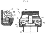
- sensor housing 9b has the same outer contour as the sensor housing 9a, but stored in the inner liquid-conducting part 12, a passive, ie non-driven pump impeller 16 which is driven by the flowing through liquid, ie rotated.
- magnets 17 are arranged, which run at a small distance from the wall 1.
- coils 18 are provided, in which when passing the magnets 16, a current is generated, which is used for the electrical power supply of the sensor housing 9b sensors and electronics.
- the sensor signals or the data determined therefrom are either inductively fed into the cable 7 guided there on the housing 9b via a data cable or else inductively.
- a two-armed wing 19 is provided, which carries at its ends magnet 17, in the same manner as with reference to Fig. 3 previously described serve to generate electricity.
- the wings 19 are inclined with their end faces, so that they are also set in flow in rotation, but have a relation to the impeller 16 significantly lower flow resistance.
- the sensor housing is an integral part of the pump housing or is inextricably connected to the pump housing.
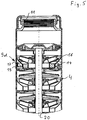
- the drive shaft for the impellers of the centrifugal pump 4 is extended upward and carries at the upper end of a pump impeller 16, which is an active impeller due to the drive through the shaft 20.
- a sensor housing 9d whose wall 14 separates the liquid-free housing part 13 from the rest of the pump housing.
- magnets are arranged at the bottom, in the same way as with reference to Fig. 3 previously described cooperate with corresponding coils 18 in the liquid-free housing part 13 and provide for the power supply within the sensor housing 9d.
- the sensor housing 9d may also be formed by modifying any pumping stage. It can therefore be provided 9d also a plurality of sensor housing, if z. B. several pump stages to be monitored.
- the sensor housing 9e is also firmly connected to the last stage of the centrifugal pump 4, but there is the pump impeller 16 mounted within the sensor housing 9e freely rotatable, ie as a passive pump impeller similar to the arrangement according to Fig. 3 educated. Again, the power supply of the sensor via magnets 17 on the underside of the pump impeller 16, which cooperate with arranged within the liquid-free housing part 13 coils.
- a multi-stage centrifugal pump 4 In the illustration according to Fig. 7 the upper end of a multi-stage centrifugal pump 4 is shown on the left, the lower end connects to the engine part 3, which is shown on the right. Through the housing part performs a common shaft 20, which continues in the engine part 3.
- the attached at the upper end of the pump 4 sensor housing 9 f corresponds substantially to the basis of Fig. 3 provided and explained. However, here is a signal transmission from the liquid-free housing part 13 out through the liquid through to the shaft 20 by mechanical waves.
- an electroacoustic transducer is provided within the liquid-free housing part 13 of the sensor housing 9f, which converts the sensor signals into ultrasonic signals, which are transmitted via the liquid to the shaft 20.
- an acoustoelectric transducer 21 At the motor end of the shaft 20, an acoustoelectric transducer 21 is provided, which converts these mechanical vibrations back into an electrical signal, which is then passed through the supply cable 7 of the motor to the supply and control housing
- the shaft 20 is guided into the sensor housing 9 g, on which a pump impeller 16th the above-described training according to Fig. 3 .rius.
- This pump impeller 16 is thus actively driven by the shaft 20.
Landscapes
- Engineering & Computer Science (AREA)
- Mining & Mineral Resources (AREA)
- Geology (AREA)
- Life Sciences & Earth Sciences (AREA)
- Physics & Mathematics (AREA)
- Environmental & Geological Engineering (AREA)
- Fluid Mechanics (AREA)
- General Life Sciences & Earth Sciences (AREA)
- Geochemistry & Mineralogy (AREA)
- Mechanical Engineering (AREA)
- General Engineering & Computer Science (AREA)
- Geophysics (AREA)
- Structures Of Non-Positive Displacement Pumps (AREA)
- Control Of Non-Positive-Displacement Pumps (AREA)
Claims (2)
- Pompe de forage (1) comprenant un moteur d'entraînement électrique (3) et une pompe centrifuge (4) à un ou plusieurs étages entraînée par ce moteur et équipée d'un ou de plusieurs capteur(s), qui est ou sont disposé(s) dans un carter de capteur (9) traversé par le liquide et entouré par le liquide, qui présente une partie de carter (12) qui conduit le liquide et une partie de carter libre de liquide (13), lesquelles sont séparées l'une de l'autre par une paroi (14) du carter, lequel carter est disposé entre le moteur (3) et la pompe (4), à l'extrémité de la pompe (4) ou à l'intérieur de la pompe (4), un dispositif à induction (17, 18) étant prévu dans le carter de capteur (9) au moyen duquel de l'énergie électrique est produite pendant le fonctionnement de la pompe (4), caractérisée en ce que le dispositif à induction (17, 18) présente au moins un aimant (17) disposé de façon rotative dans la partie de carter (12) qui conduit le liquide, et en ce qu'au moins une bobine d'induction (18) est disposée dans la partie de carter libre de liquid et en ce qu'il est prévu des moyens (20, 21) pour transmettre des signaux et/ou des données du carter de capteur (9) au carter de moteur, la transmission de signaux et/ou de données s'effectuant par voie mécanique à travers l'arbre (20) et qu'il est prévu à cet effet, sur le côté carter de capteur, un convertisseur électroacoustique qui agit sur l'arbre (20) et, sur le côté moteur, un convertisseur acoustico-électrique (21).
- Pompe de forage (1) selon l'une des revendecations précédentes, caractérisée en ce que le carter de capteur (9) comporte un capteur de température, un capteur de vibration, un débitmètre et/ou un capteur de pression ou de pression différentielle.
Priority Applications (3)
| Application Number | Priority Date | Filing Date | Title |
|---|---|---|---|
| EP07024940.4A EP2072829B2 (fr) | 2007-12-21 | 2007-12-21 | Pompe submersible |
| US12/339,201 US8454330B2 (en) | 2007-12-21 | 2008-12-19 | Submersible pump |
| CN2008101853538A CN101487473B (zh) | 2007-12-21 | 2008-12-22 | 深井泵 |
Applications Claiming Priority (1)
| Application Number | Priority Date | Filing Date | Title |
|---|---|---|---|
| EP07024940.4A EP2072829B2 (fr) | 2007-12-21 | 2007-12-21 | Pompe submersible |
Publications (3)
| Publication Number | Publication Date |
|---|---|
| EP2072829A1 EP2072829A1 (fr) | 2009-06-24 |
| EP2072829B1 EP2072829B1 (fr) | 2014-12-17 |
| EP2072829B2 true EP2072829B2 (fr) | 2017-12-20 |
Family
ID=39477558
Family Applications (1)
| Application Number | Title | Priority Date | Filing Date |
|---|---|---|---|
| EP07024940.4A Not-in-force EP2072829B2 (fr) | 2007-12-21 | 2007-12-21 | Pompe submersible |
Country Status (3)
| Country | Link |
|---|---|
| US (1) | US8454330B2 (fr) |
| EP (1) | EP2072829B2 (fr) |
| CN (1) | CN101487473B (fr) |
Families Citing this family (19)
| Publication number | Priority date | Publication date | Assignee | Title |
|---|---|---|---|---|
| EP2309133B1 (fr) * | 2009-10-05 | 2015-07-15 | Grundfos Management A/S | Agrégat de pompes submersibles |
| US8347953B1 (en) * | 2009-12-11 | 2013-01-08 | Ge Oil & Gas Esp, Inc. | Inline monitoring package for electrical submersible pump |
| CN101915243B (zh) * | 2010-07-09 | 2012-07-11 | 美的集团有限公司 | 冷风扇潜水泵的排空装置及控制方法 |
| US8727737B2 (en) * | 2010-10-22 | 2014-05-20 | Grundfos Pumps Corporation | Submersible pump system |
| US9121270B2 (en) | 2011-05-26 | 2015-09-01 | Grundfos Pumps Corporation | Pump system |
| DE102012200806B4 (de) * | 2012-01-20 | 2014-07-31 | Yasa Motors Poland Sp. z.o.o. | Nassläuferpumpe mit Leistungselektronik |
| GB2515263B (en) * | 2013-04-26 | 2015-09-09 | Rotech Group Ltd | Improved turbine |
| CA2944635A1 (fr) | 2014-04-03 | 2015-10-08 | Schlumberger Canada Limited | Estimation d'etat et prediction de la duree de vie de fonctionnement de systeme de pompage |
| CN104165135B (zh) * | 2014-07-08 | 2016-03-09 | 中国石油天然气集团公司 | 潜油电泵传感器免注油快速连接装置 |
| DK3184823T3 (da) * | 2015-12-21 | 2019-07-08 | Grundfos Holding As | Centrifugalpumpe |
| WO2018022198A1 (fr) * | 2016-07-26 | 2018-02-01 | Schlumberger Technology Corporation | Système de pompage électrique submersible intégré avec impulseur à entraînement électromagnétique |
| CN110121598B (zh) * | 2016-12-30 | 2021-08-03 | 格兰富控股联合股份公司 | 传感器组件、泵中的故障检测方法、及包括该传感器组件的泵组件 |
| US10876534B2 (en) * | 2017-08-01 | 2020-12-29 | Baker Hughes, A Ge Company, Llc | Combined pump and motor with a stator forming a cavity which houses an impeller between upper and lower diffusers with the impeller having a circumferential magnet array extending upward and downward into diffuser annular clearances |
| ES2827500T3 (es) * | 2018-03-26 | 2021-05-21 | Xylem Europe Gmbh | Máquina eléctrica sumergible |
| WO2020198446A1 (fr) | 2019-03-26 | 2020-10-01 | Schlumberger Technology Corporation | Systèmes de pompage submersibles électriques |
| EP3744981B1 (fr) * | 2019-05-28 | 2024-08-07 | Grundfos Holding A/S | Ensemble de pompe submersible et procédé de fonctionnement de l'ensemble de pompe submersible |
| DE102019004263A1 (de) * | 2019-06-18 | 2020-12-24 | KSB SE & Co. KGaA | Kreiselpumpe und Verfahren zur Zustandserkennung einer Kreiselpumpe |
| ES3036218T3 (en) * | 2021-05-12 | 2025-09-16 | Grundfos Holding As | Centrifugal pump |
| CN115788919A (zh) | 2021-09-09 | 2023-03-14 | 创科无线普通合伙 | 潜水泵 |
Citations (7)
| Publication number | Priority date | Publication date | Assignee | Title |
|---|---|---|---|---|
| EP0033192A1 (fr) † | 1980-01-21 | 1981-08-05 | Sperry Corporation | Système pour la propagation acoustique de données le long d'une tige de forage dans un puits de forage |
| DE4013978A1 (de) † | 1990-05-01 | 1991-11-07 | Innotech Microelectronik Gmbh | Datenuebertragung mittels ultraschall ueber sich bewegende maschinenelemente |
| US5148408A (en) † | 1990-11-05 | 1992-09-15 | Teleco Oilfield Services Inc. | Acoustic data transmission method |
| DE19728392A1 (de) † | 1997-07-03 | 1999-01-07 | Mantel Juval | Fluidströmungsmesser |
| JP2006170903A (ja) † | 2004-12-17 | 2006-06-29 | Shin Nippon Air Technol Co Ltd | 発電機付流量計 |
| RU2285155C1 (ru) † | 2005-09-16 | 2006-10-10 | Михаил Яковлевич Либкин | Скважинная насосная установка |
| US20070114040A1 (en) † | 2005-11-22 | 2007-05-24 | Schlumberger Technology Corporation | System and Method for Sensing Parameters in a Wellbore |
Family Cites Families (11)
| Publication number | Priority date | Publication date | Assignee | Title |
|---|---|---|---|---|
| US2550667A (en) * | 1944-08-01 | 1951-05-01 | Byron Jackson Co | Seal structure |
| US3021788A (en) | 1957-05-02 | 1962-02-20 | American Crucible Products Com | Submersible pump |
| US2969740A (en) | 1957-05-27 | 1961-01-31 | American Crucible Products Com | Pump control |
| US3867655A (en) * | 1973-11-21 | 1975-02-18 | Entropy Ltd | Shaftless energy conversion device |
| US6811382B2 (en) * | 2000-10-18 | 2004-11-02 | Schlumberger Technology Corporation | Integrated pumping system for use in pumping a variety of fluids |
| US6612188B2 (en) * | 2001-01-03 | 2003-09-02 | Neptune Technology Group Inc. | Self-powered fluid meter |
| SE0104317L (sv) | 2001-12-20 | 2002-11-26 | Itt Mfg Enterprises Inc | Avkänningsanordning för vätskeflödet i ett pumputlopp avsedd att styra strömtillförseln till den elektriskt drivan pumpmotorn |
| US6695052B2 (en) * | 2002-01-08 | 2004-02-24 | Schlumberger Technology Corporation | Technique for sensing flow related parameters when using an electric submersible pumping system to produce a desired fluid |
| FI20041480A0 (fi) * | 2004-11-17 | 2004-11-17 | Pom Technology Oy Ab | Anturilla varustettu kaasua erottava keskipakoislaite |
| US7571770B2 (en) * | 2005-03-23 | 2009-08-11 | Baker Hughes Incorporated | Downhole cooling based on thermo-tunneling of electrons |
| US7277026B2 (en) * | 2005-05-21 | 2007-10-02 | Hall David R | Downhole component with multiple transmission elements |
-
2007
- 2007-12-21 EP EP07024940.4A patent/EP2072829B2/fr not_active Not-in-force
-
2008
- 2008-12-19 US US12/339,201 patent/US8454330B2/en not_active Expired - Fee Related
- 2008-12-22 CN CN2008101853538A patent/CN101487473B/zh not_active Expired - Fee Related
Patent Citations (7)
| Publication number | Priority date | Publication date | Assignee | Title |
|---|---|---|---|---|
| EP0033192A1 (fr) † | 1980-01-21 | 1981-08-05 | Sperry Corporation | Système pour la propagation acoustique de données le long d'une tige de forage dans un puits de forage |
| DE4013978A1 (de) † | 1990-05-01 | 1991-11-07 | Innotech Microelectronik Gmbh | Datenuebertragung mittels ultraschall ueber sich bewegende maschinenelemente |
| US5148408A (en) † | 1990-11-05 | 1992-09-15 | Teleco Oilfield Services Inc. | Acoustic data transmission method |
| DE19728392A1 (de) † | 1997-07-03 | 1999-01-07 | Mantel Juval | Fluidströmungsmesser |
| JP2006170903A (ja) † | 2004-12-17 | 2006-06-29 | Shin Nippon Air Technol Co Ltd | 発電機付流量計 |
| RU2285155C1 (ru) † | 2005-09-16 | 2006-10-10 | Михаил Яковлевич Либкин | Скважинная насосная установка |
| US20070114040A1 (en) † | 2005-11-22 | 2007-05-24 | Schlumberger Technology Corporation | System and Method for Sensing Parameters in a Wellbore |
Also Published As
| Publication number | Publication date |
|---|---|
| CN101487473B (zh) | 2011-12-07 |
| US20090162223A1 (en) | 2009-06-25 |
| EP2072829B1 (fr) | 2014-12-17 |
| EP2072829A1 (fr) | 2009-06-24 |
| CN101487473A (zh) | 2009-07-22 |
| US8454330B2 (en) | 2013-06-04 |
Similar Documents
| Publication | Publication Date | Title |
|---|---|---|
| EP2072829B2 (fr) | Pompe submersible | |
| EP1564411A1 (fr) | Procédé de detection des erreurs de fonctionnement d'une unité de pompage | |
| EP3138791B1 (fr) | Moteur a tambour et cartouche de capteur pour un moteur a tambour | |
| DE69106120T2 (de) | Vorrichtung zum messen der positionsänderung eines rotors. | |
| EP2258949B1 (fr) | Procédé de détermination de valeurs caractéristiques, notamment de valeurs, notamment de paramètres, d'un agrégat de pompe centrifuge entraîné par moteur électrique intégré dans une installation | |
| EP0232891A2 (fr) | Outil de forage pour puits profonds | |
| DE102009022107A1 (de) | Verfahren und Vorrichtung zur Betriebspunktbestimmung einer Arbeitsmaschine | |
| DE102010037379A1 (de) | Pumpenanordnung mit integrierter Vibrationsmessung | |
| DE3820003A1 (de) | Tauchpumpenaggregat | |
| EP3315784A1 (fr) | Tauchpumpenaggregat und verfahren zum betreiben eines tauchpumpenaggregates | |
| EP3293495A1 (fr) | Machine comprenant un arbre creux refroidi et capteur rotatif concentrique | |
| EP3527829B1 (fr) | Système de pompe et procédé de commande de pompe | |
| DE102009001353A1 (de) | Elektromaschine mit Rotorlagesensor | |
| WO2016166114A1 (fr) | Pompe et procédé pour faire fonctionner une pompe pour liquides | |
| EP3973185B1 (fr) | Pompe à cavité progressive | |
| EP3184823B1 (fr) | Pompe centrifuge | |
| DE102017001429A1 (de) | Elektromaschine mit einer Vorrichtung zur Kühlluftführung | |
| EP2154376A2 (fr) | Réduction du bruit d'une pompe électrique | |
| EP1597483A1 (fr) | Pompe tubulaire optimisee en oscillations | |
| EP2721301A1 (fr) | Pompe submersible et procédé d'assemblage d'une pompe submersible | |
| DE102011082270B4 (de) | Lagervorrichtung mit einer Energieerzeugungseinheit | |
| DE102005042776A1 (de) | Sensoranordnung | |
| EP4386150A1 (fr) | Procédé d'obtention d'informations dans un groupe motopompe d'eaux usées et/ou un système de pompe d'eaux usées | |
| EP2246580A1 (fr) | Commande de l'alimentation de lubrifiant d'un palier lisse et dispositif correspondant | |
| EP2060793B1 (fr) | Pompe à vide |
Legal Events
| Date | Code | Title | Description |
|---|---|---|---|
| PUAI | Public reference made under article 153(3) epc to a published international application that has entered the european phase |
Free format text: ORIGINAL CODE: 0009012 |
|
| AK | Designated contracting states |
Kind code of ref document: A1 Designated state(s): AT BE BG CH CY CZ DE DK EE ES FI FR GB GR HU IE IS IT LI LT LU LV MC MT NL PL PT RO SE SI SK TR |
|
| AX | Request for extension of the european patent |
Extension state: AL BA HR MK RS |
|
| 17P | Request for examination filed |
Effective date: 20091028 |
|
| 17Q | First examination report despatched |
Effective date: 20091125 |
|
| AKX | Designation fees paid |
Designated state(s): AT BE BG CH CY CZ DE DK EE ES FI FR GB GR HU IE IS IT LI LT LU LV MC MT NL PL PT RO SE SI SK TR |
|
| GRAP | Despatch of communication of intention to grant a patent |
Free format text: ORIGINAL CODE: EPIDOSNIGR1 |
|
| INTG | Intention to grant announced |
Effective date: 20140716 |
|
| GRAS | Grant fee paid |
Free format text: ORIGINAL CODE: EPIDOSNIGR3 |
|
| GRAA | (expected) grant |
Free format text: ORIGINAL CODE: 0009210 |
|
| AK | Designated contracting states |
Kind code of ref document: B1 Designated state(s): AT BE BG CH CY CZ DE DK EE ES FI FR GB GR HU IE IS IT LI LT LU LV MC MT NL PL PT RO SE SI SK TR |
|
| REG | Reference to a national code |
Ref country code: GB Ref legal event code: FG4D Free format text: NOT ENGLISH |
|
| REG | Reference to a national code |
Ref country code: CH Ref legal event code: EP |
|
| REG | Reference to a national code |
Ref country code: IE Ref legal event code: FG4D Free format text: LANGUAGE OF EP DOCUMENT: GERMAN |
|
| REG | Reference to a national code |
Ref country code: AT Ref legal event code: REF Ref document number: 702148 Country of ref document: AT Kind code of ref document: T Effective date: 20150115 |
|
| REG | Reference to a national code |
Ref country code: DE Ref legal event code: R096 Ref document number: 502007013627 Country of ref document: DE Effective date: 20150129 |
|
| PG25 | Lapsed in a contracting state [announced via postgrant information from national office to epo] |
Ref country code: LT Free format text: LAPSE BECAUSE OF FAILURE TO SUBMIT A TRANSLATION OF THE DESCRIPTION OR TO PAY THE FEE WITHIN THE PRESCRIBED TIME-LIMIT Effective date: 20141217 Ref country code: FI Free format text: LAPSE BECAUSE OF FAILURE TO SUBMIT A TRANSLATION OF THE DESCRIPTION OR TO PAY THE FEE WITHIN THE PRESCRIBED TIME-LIMIT Effective date: 20141217 |
|
| REG | Reference to a national code |
Ref country code: LT Ref legal event code: MG4D |
|
| PG25 | Lapsed in a contracting state [announced via postgrant information from national office to epo] |
Ref country code: LV Free format text: LAPSE BECAUSE OF FAILURE TO SUBMIT A TRANSLATION OF THE DESCRIPTION OR TO PAY THE FEE WITHIN THE PRESCRIBED TIME-LIMIT Effective date: 20141217 Ref country code: SE Free format text: LAPSE BECAUSE OF FAILURE TO SUBMIT A TRANSLATION OF THE DESCRIPTION OR TO PAY THE FEE WITHIN THE PRESCRIBED TIME-LIMIT Effective date: 20141217 Ref country code: GR Free format text: LAPSE BECAUSE OF FAILURE TO SUBMIT A TRANSLATION OF THE DESCRIPTION OR TO PAY THE FEE WITHIN THE PRESCRIBED TIME-LIMIT Effective date: 20150318 |
|
| PG25 | Lapsed in a contracting state [announced via postgrant information from national office to epo] |
Ref country code: BE Free format text: LAPSE BECAUSE OF NON-PAYMENT OF DUE FEES Effective date: 20141231 Ref country code: NL Free format text: LAPSE BECAUSE OF FAILURE TO SUBMIT A TRANSLATION OF THE DESCRIPTION OR TO PAY THE FEE WITHIN THE PRESCRIBED TIME-LIMIT Effective date: 20141217 |
|
| PG25 | Lapsed in a contracting state [announced via postgrant information from national office to epo] |
Ref country code: CZ Free format text: LAPSE BECAUSE OF FAILURE TO SUBMIT A TRANSLATION OF THE DESCRIPTION OR TO PAY THE FEE WITHIN THE PRESCRIBED TIME-LIMIT Effective date: 20141217 Ref country code: EE Free format text: LAPSE BECAUSE OF FAILURE TO SUBMIT A TRANSLATION OF THE DESCRIPTION OR TO PAY THE FEE WITHIN THE PRESCRIBED TIME-LIMIT Effective date: 20141217 Ref country code: SK Free format text: LAPSE BECAUSE OF FAILURE TO SUBMIT A TRANSLATION OF THE DESCRIPTION OR TO PAY THE FEE WITHIN THE PRESCRIBED TIME-LIMIT Effective date: 20141217 Ref country code: ES Free format text: LAPSE BECAUSE OF FAILURE TO SUBMIT A TRANSLATION OF THE DESCRIPTION OR TO PAY THE FEE WITHIN THE PRESCRIBED TIME-LIMIT Effective date: 20141217 Ref country code: RO Free format text: LAPSE BECAUSE OF FAILURE TO SUBMIT A TRANSLATION OF THE DESCRIPTION OR TO PAY THE FEE WITHIN THE PRESCRIBED TIME-LIMIT Effective date: 20141217 |
|
| REG | Reference to a national code |
Ref country code: CH Ref legal event code: PL |
|
| PG25 | Lapsed in a contracting state [announced via postgrant information from national office to epo] |
Ref country code: PL Free format text: LAPSE BECAUSE OF FAILURE TO SUBMIT A TRANSLATION OF THE DESCRIPTION OR TO PAY THE FEE WITHIN THE PRESCRIBED TIME-LIMIT Effective date: 20141217 Ref country code: IS Free format text: LAPSE BECAUSE OF FAILURE TO SUBMIT A TRANSLATION OF THE DESCRIPTION OR TO PAY THE FEE WITHIN THE PRESCRIBED TIME-LIMIT Effective date: 20150417 |
|
| REG | Reference to a national code |
Ref country code: DE Ref legal event code: R026 Ref document number: 502007013627 Country of ref document: DE |
|
| REG | Reference to a national code |
Ref country code: IE Ref legal event code: MM4A |
|
| PLBI | Opposition filed |
Free format text: ORIGINAL CODE: 0009260 |
|
| PG25 | Lapsed in a contracting state [announced via postgrant information from national office to epo] |
Ref country code: MC Free format text: LAPSE BECAUSE OF FAILURE TO SUBMIT A TRANSLATION OF THE DESCRIPTION OR TO PAY THE FEE WITHIN THE PRESCRIBED TIME-LIMIT Effective date: 20141217 |
|
| REG | Reference to a national code |
Ref country code: FR Ref legal event code: PLFP Year of fee payment: 9 |
|
| PLAX | Notice of opposition and request to file observation + time limit sent |
Free format text: ORIGINAL CODE: EPIDOSNOBS2 |
|
| 26 | Opposition filed |
Opponent name: KSB AKTIENGESELLSCHAFT Effective date: 20150916 |
|
| PG25 | Lapsed in a contracting state [announced via postgrant information from national office to epo] |
Ref country code: CH Free format text: LAPSE BECAUSE OF NON-PAYMENT OF DUE FEES Effective date: 20141231 Ref country code: IE Free format text: LAPSE BECAUSE OF NON-PAYMENT OF DUE FEES Effective date: 20141221 Ref country code: DK Free format text: LAPSE BECAUSE OF FAILURE TO SUBMIT A TRANSLATION OF THE DESCRIPTION OR TO PAY THE FEE WITHIN THE PRESCRIBED TIME-LIMIT Effective date: 20141217 Ref country code: LI Free format text: LAPSE BECAUSE OF NON-PAYMENT OF DUE FEES Effective date: 20141231 |
|
| REG | Reference to a national code |
Ref country code: AT Ref legal event code: MM01 Ref document number: 702148 Country of ref document: AT Kind code of ref document: T Effective date: 20141221 |
|
| PLBB | Reply of patent proprietor to notice(s) of opposition received |
Free format text: ORIGINAL CODE: EPIDOSNOBS3 |
|
| PG25 | Lapsed in a contracting state [announced via postgrant information from national office to epo] |
Ref country code: SI Free format text: LAPSE BECAUSE OF FAILURE TO SUBMIT A TRANSLATION OF THE DESCRIPTION OR TO PAY THE FEE WITHIN THE PRESCRIBED TIME-LIMIT Effective date: 20141217 |
|
| PG25 | Lapsed in a contracting state [announced via postgrant information from national office to epo] |
Ref country code: BG Free format text: LAPSE BECAUSE OF FAILURE TO SUBMIT A TRANSLATION OF THE DESCRIPTION OR TO PAY THE FEE WITHIN THE PRESCRIBED TIME-LIMIT Effective date: 20141217 Ref country code: AT Free format text: LAPSE BECAUSE OF NON-PAYMENT OF DUE FEES Effective date: 20141221 |
|
| PG25 | Lapsed in a contracting state [announced via postgrant information from national office to epo] |
Ref country code: PT Free format text: LAPSE BECAUSE OF FAILURE TO SUBMIT A TRANSLATION OF THE DESCRIPTION OR TO PAY THE FEE WITHIN THE PRESCRIBED TIME-LIMIT Effective date: 20141217 Ref country code: CY Free format text: LAPSE BECAUSE OF FAILURE TO SUBMIT A TRANSLATION OF THE DESCRIPTION OR TO PAY THE FEE WITHIN THE PRESCRIBED TIME-LIMIT Effective date: 20141217 |
|
| PG25 | Lapsed in a contracting state [announced via postgrant information from national office to epo] |
Ref country code: MT Free format text: LAPSE BECAUSE OF FAILURE TO SUBMIT A TRANSLATION OF THE DESCRIPTION OR TO PAY THE FEE WITHIN THE PRESCRIBED TIME-LIMIT Effective date: 20141217 Ref country code: HU Free format text: LAPSE BECAUSE OF FAILURE TO SUBMIT A TRANSLATION OF THE DESCRIPTION OR TO PAY THE FEE WITHIN THE PRESCRIBED TIME-LIMIT; INVALID AB INITIO Effective date: 20071221 Ref country code: LU Free format text: LAPSE BECAUSE OF NON-PAYMENT OF DUE FEES Effective date: 20141221 Ref country code: TR Free format text: LAPSE BECAUSE OF FAILURE TO SUBMIT A TRANSLATION OF THE DESCRIPTION OR TO PAY THE FEE WITHIN THE PRESCRIBED TIME-LIMIT Effective date: 20141217 |
|
| REG | Reference to a national code |
Ref country code: FR Ref legal event code: PLFP Year of fee payment: 10 |
|
| REG | Reference to a national code |
Ref country code: FR Ref legal event code: PLFP Year of fee payment: 11 |
|
| PUAH | Patent maintained in amended form |
Free format text: ORIGINAL CODE: 0009272 |
|
| STAA | Information on the status of an ep patent application or granted ep patent |
Free format text: STATUS: PATENT MAINTAINED AS AMENDED |
|
| 27A | Patent maintained in amended form |
Effective date: 20171220 |
|
| AK | Designated contracting states |
Kind code of ref document: B2 Designated state(s): AT BE BG CH CY CZ DE DK EE ES FI FR GB GR HU IE IS IT LI LT LU LV MC MT NL PL PT RO SE SI SK TR |
|
| REG | Reference to a national code |
Ref country code: DE Ref legal event code: R102 Ref document number: 502007013627 Country of ref document: DE |
|
| PG25 | Lapsed in a contracting state [announced via postgrant information from national office to epo] |
Ref country code: LV Free format text: LAPSE BECAUSE OF FAILURE TO SUBMIT A TRANSLATION OF THE DESCRIPTION OR TO PAY THE FEE WITHIN THE PRESCRIBED TIME-LIMIT Effective date: 20141217 |
|
| REG | Reference to a national code |
Ref country code: DE Ref legal event code: R082 Ref document number: 502007013627 Country of ref document: DE |
|
| PGFP | Annual fee paid to national office [announced via postgrant information from national office to epo] |
Ref country code: GB Payment date: 20231220 Year of fee payment: 17 |
|
| PGFP | Annual fee paid to national office [announced via postgrant information from national office to epo] |
Ref country code: IT Payment date: 20231228 Year of fee payment: 17 Ref country code: FR Payment date: 20231221 Year of fee payment: 17 Ref country code: DE Payment date: 20231214 Year of fee payment: 17 |
|
| REG | Reference to a national code |
Ref country code: DE Ref legal event code: R119 Ref document number: 502007013627 Country of ref document: DE |
|
| GBPC | Gb: european patent ceased through non-payment of renewal fee |
Effective date: 20241221 |
|
| PG25 | Lapsed in a contracting state [announced via postgrant information from national office to epo] |
Ref country code: DE Free format text: LAPSE BECAUSE OF NON-PAYMENT OF DUE FEES Effective date: 20250701 |
|
| PG25 | Lapsed in a contracting state [announced via postgrant information from national office to epo] |
Ref country code: IT Free format text: LAPSE BECAUSE OF NON-PAYMENT OF DUE FEES Effective date: 20241221 |
|
| PG25 | Lapsed in a contracting state [announced via postgrant information from national office to epo] |
Ref country code: GB Free format text: LAPSE BECAUSE OF NON-PAYMENT OF DUE FEES Effective date: 20241221 |
|
| PG25 | Lapsed in a contracting state [announced via postgrant information from national office to epo] |
Ref country code: FR Free format text: LAPSE BECAUSE OF NON-PAYMENT OF DUE FEES Effective date: 20241231 |