EP2072829B2 - Immersion pump - Google Patents
Immersion pump Download PDFInfo
- Publication number
- EP2072829B2 EP2072829B2 EP07024940.4A EP07024940A EP2072829B2 EP 2072829 B2 EP2072829 B2 EP 2072829B2 EP 07024940 A EP07024940 A EP 07024940A EP 2072829 B2 EP2072829 B2 EP 2072829B2
- Authority
- EP
- European Patent Office
- Prior art keywords
- pump
- housing
- sensor
- sensor housing
- motor
- Prior art date
- Legal status (The legal status is an assumption and is not a legal conclusion. Google has not performed a legal analysis and makes no representation as to the accuracy of the status listed.)
- Not-in-force
Links
Images


Classifications
-
- F—MECHANICAL ENGINEERING; LIGHTING; HEATING; WEAPONS; BLASTING
- F04—POSITIVE - DISPLACEMENT MACHINES FOR LIQUIDS; PUMPS FOR LIQUIDS OR ELASTIC FLUIDS
- F04D—NON-POSITIVE-DISPLACEMENT PUMPS
- F04D13/00—Pumping installations or systems
- F04D13/02—Units comprising pumps and their driving means
- F04D13/06—Units comprising pumps and their driving means the pump being electrically driven
- F04D13/08—Units comprising pumps and their driving means the pump being electrically driven for submerged use
- F04D13/10—Units comprising pumps and their driving means the pump being electrically driven for submerged use adapted for use in mining bore holes
-
- E—FIXED CONSTRUCTIONS
- E21—EARTH OR ROCK DRILLING; MINING
- E21B—EARTH OR ROCK DRILLING; OBTAINING OIL, GAS, WATER, SOLUBLE OR MELTABLE MATERIALS OR A SLURRY OF MINERALS FROM WELLS
- E21B43/00—Methods or apparatus for obtaining oil, gas, water, soluble or meltable materials or a slurry of minerals from wells
- E21B43/12—Methods or apparatus for controlling the flow of the obtained fluid to or in wells
- E21B43/121—Lifting well fluids
- E21B43/128—Adaptation of pump systems with down-hole electric drives
-
- E—FIXED CONSTRUCTIONS
- E21—EARTH OR ROCK DRILLING; MINING
- E21B—EARTH OR ROCK DRILLING; OBTAINING OIL, GAS, WATER, SOLUBLE OR MELTABLE MATERIALS OR A SLURRY OF MINERALS FROM WELLS
- E21B47/00—Survey of boreholes or wells
- E21B47/008—Monitoring of down-hole pump systems, e.g. for the detection of "pumped-off" conditions
-
- F—MECHANICAL ENGINEERING; LIGHTING; HEATING; WEAPONS; BLASTING
- F04—POSITIVE - DISPLACEMENT MACHINES FOR LIQUIDS; PUMPS FOR LIQUIDS OR ELASTIC FLUIDS
- F04D—NON-POSITIVE-DISPLACEMENT PUMPS
- F04D13/00—Pumping installations or systems
- F04D13/02—Units comprising pumps and their driving means
- F04D13/06—Units comprising pumps and their driving means the pump being electrically driven
- F04D13/08—Units comprising pumps and their driving means the pump being electrically driven for submerged use
Definitions
- the invention relates to a borehole pump according to the features specified in the preamble of claim 1.
- the invention has the object, a generic borehole pump in such a way that one or more sensors can be arranged inexpensively at a suitable location and corresponding signal or data connected.
- the borehole pump according to the invention has an electric drive motor and a single-stage or multi-stage centrifugal pump driven by it.
- one or more sensors of the pump are arranged in a sensor housing, which, liquid flows through and liquid surrounds.
- the sensor housing is located between the motor and the pump, at the end of the pump or inside the pump.
- the sensor housing can either be arranged as a separate housing at the end of the pump or form part of the pump housing, so be formed integrally with this.
- the basic idea of the present invention is, if possible, to accommodate the complete sensor system, but at least one or more sensors in a separate sensor housing, which at the end the pump, within the pump or between the motor and the pump, that is arranged at the other end of the pump.
- This sensor housing may have a modular design, so that it can optionally be retrofitted to existing pumps or at least pumps of the same series can be equipped with or without sensor housing, so can be shipped with and without sensors. Since the sensor housing is arranged between the motor and pump, within the pump or at the end of the pump, the borehole pump is thereby not changed in its outer contour, but only in their length, which is particularly important for borehole pumps.
- the sensor housing according to the invention is designed and arranged in such a way that liquid flows through it and liquid is surrounded on the one hand. For example, temperatures and / or pressure can be detected by both the surrounding and the delivered fluid. Since, if possible, the entire sensor system or at least a large part is arranged inside the sensor housing, only that sensor housing needs to be provided with an outwardly directed cable, which is an advantage in borehole pumps when the sensor housing is arranged at the upper end of the pump on which anyway only the power cable runs next to the conveyor line. In the arrangement between the motor and pump, there is the advantage that the wiring can be done via the motor, which anyway requires a cable to the outside to the electrical power supply and possibly also to the control electronics.
- the sensor housing is divided into a liquid-conducting housing part and a liquid-free housing part, which are separated by a preferably formed by stainless steel sheet housing wall.
- a housing wall may be formed in the manner of a split tube comparatively thin but absolutely liquid-tight, so that, with the exception of the pressure and / or differential pressure sensors, if necessary, it is also possible to measure through the housing wall, for example temperature, vibration and the like.
- the entire flow of the pump is passed through the liquid-carrying housing part, wherein the housing part is formed so that it is almost a further pump stage or a pipe extension, that provides as little flow resistance.
- the sensors located in the sensor housing and possibly electronics requires comparatively little space, so that a small circumferential free space is usually sufficient to accommodate these components.
- the electrical energy required to operate the sensors arranged in the sensor housing and, if necessary, reprocess the electrical signals emanating therefrom, process them and convert them into digital data can be generated directly within the sensor housing in order to be present completely dispense with a line for powering the sensor housing.
- an induction arrangement is provided in the sensor housing, with which electrical energy is generated during operation of the pump.
- the induction arrangement has at least one magnet rotatably arranged in the liquid-conducting housing part and at least one arranged in the liquid-free housing part induction coil, such that a current in the coil is induced by the magnet moving past the coil, which is usable for the aforementioned purposes .
- two or more magnets are arranged, which cooperate with possibly a plurality of induction coils and thus form a kind of electrical generator.
- a drive for the magnets In order to form a drive for the magnets is provided according to a development of the invention, rotatably support a pump impeller within the liquid-conducting housing part and to be arranged so that it is rotated by the flow rate of the pump in rotation.
- the sensor housing is quasi designed as a further passive pump stage, the flow passing through it drives the impeller mounted thereon with the magnets attached thereto, thereby inducing a voltage in the one or more coils or generate a current and thus the sensor within the housing Supply electricity.
- such a passive pump impeller which is arranged freely rotatable within the sensor housing, and on which at least one magnet is arranged, also form part of a flow meter, wherein then within the liquid-free housing part, an inductive pickup, such as a coil is arranged , so that the speed of the pump impeller can be detected and above the flow rate can be determined.
- an inductive pickup such as a coil is arranged , so that the speed of the pump impeller can be detected and above the flow rate can be determined.
- It does not necessarily have a pump impeller rotatably arranged, it can be arranged rotatably a kind of wing, at the end of a magnet sits, which rotates faster or slower depending on the flow rate.
- the pump can be structurally adapted thereto, then instead of a passive impeller advantageously the drive shaft can be extended into the sensor housing inside and there are provided with a holder, which or the Magnets and is rotated by the drive shaft itself, also an active pump impeller may be provided which carries magnets.
- any desired pump stage can be designed as a sensor housing by appropriate modification. So it is also conceivable, not just one, but to provide a plurality of sensor housing to monitor, for example, the pressure of each pump stage.
- the motor is anyway an electrical supply cable, this can be used by appropriate design in a simple manner for data transmission, either by modulating the signal or by providing a further conductor. It is then expedient to transmit the electrical signals of the sensors or the data derived therefrom from the sensor housing into the motor housing.
- This is done according to the invention mechanically via the common shaft.
- an electroacoustic transducer can be provided, which converts the electrical signal into a sound signal, typically an ultrasonic signal, and transmits it directly or indirectly to the shaft.
- an acoustoelectric transducer is then provided, which converts this signal back into an electrical signal, which is then led out in a suitable manner.
- sensors may be arranged, typically one or more temperature sensors for detecting the temperature of the flow and / or the surrounding medium, a vibration sensor for detecting mechanical vibrations, a pressure or differential pressure sensor for detecting the ambient pressure and / or the delivery pressure. This list is only an example and can be supplemented by any other sensors.
- At least the sensors which need not necessarily be in communication with the surrounding or conveyed liquid, such.
- Fig. 1 illustrated well pump 1 is lowered in a borehole 2. It consists of a lower engine part 3, of which in Fig. 1 only the motor housing is visible, this is followed up to a multi-stage centrifugal pump 4, the pump stages in Fig. 1 are indicated. Between engine 3 and pump 4 there are suction openings 5 through which the liquid located in the borehole 2 is sucked, conveyed upwards by the multistage centrifugal pump 4 and finally conveyed via a pressure line 6 to the point of consumption.
- the motor 3 is supplied via a cable 7, which is guided long in the area of the centrifugal pump 4 on the outside and next to the pressure line 6 extends to a supply and control housing 8, via which the motor is supplied with power.
- a frequency converter may be provided, as well as all means for controlling and monitoring the pump.
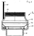
- a sensor housing 9 is arranged, the structure of which is explained below by way of example.
- sensor housing 9a is constructed rotationally symmetrical, adapted in the outer periphery to the outer periphery of the pump stages and has on its underside a threaded connector 10 which is provided for incorporation into the end-side thread of the centrifugal pump 4. From the threaded connector 10, the housing wall projects radially outward, so that it is aligned with the circumferential housing wall of the underlying pump stages 4. Towards the upper end, the housing wall is retracted and on the inside with an internal thread 11 provided, which corresponds in pitch and diameter to the internal thread at the upper end of the pump, so that the pressure line 6 can be connected either directly to the upper end of the pump or under inclusion of the sensor housing 9a.
- the sensor housing 9a has a liquid-conducting inner housing part 12 and a liquid-free outer housing part 13, which are separated from one another by a gap-like wall 14.
- the liquid-carrying housing part 12 is substantially tubular and continues to expand the cross section of the pressure line 6, in order then again to pass into the threaded neck 10.
- In the extended area of the liquid-free housing part 13 is arranged, which forms a circumferential annular space in which sensors, namely a temperature sensor on the wall 14 adjacent to detecting the temperature of the fluid, a pressure sensor, the wall 14 penetrating to detect the pressure of the pumped liquid , a pressure sensor, the outer wall penetrating to detect the ambient pressure and a vibration sensor are arranged.
- the electronics required for conditioning of the electrical signals emitted by the sensors are provided within this liquid-free housing part 13.
- the cable 15 may be merged with the cable 7 or run parallel thereto.
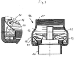
- sensor housing 9b has the same outer contour as the sensor housing 9a, but stored in the inner liquid-conducting part 12, a passive, ie non-driven pump impeller 16 which is driven by the flowing through liquid, ie rotated.
- magnets 17 are arranged, which run at a small distance from the wall 1.
- coils 18 are provided, in which when passing the magnets 16, a current is generated, which is used for the electrical power supply of the sensor housing 9b sensors and electronics.
- the sensor signals or the data determined therefrom are either inductively fed into the cable 7 guided there on the housing 9b via a data cable or else inductively.
- a two-armed wing 19 is provided, which carries at its ends magnet 17, in the same manner as with reference to Fig. 3 previously described serve to generate electricity.
- the wings 19 are inclined with their end faces, so that they are also set in flow in rotation, but have a relation to the impeller 16 significantly lower flow resistance.
- the sensor housing is an integral part of the pump housing or is inextricably connected to the pump housing.
- the drive shaft for the impellers of the centrifugal pump 4 is extended upward and carries at the upper end of a pump impeller 16, which is an active impeller due to the drive through the shaft 20.
- a sensor housing 9d whose wall 14 separates the liquid-free housing part 13 from the rest of the pump housing.
- magnets are arranged at the bottom, in the same way as with reference to Fig. 3 previously described cooperate with corresponding coils 18 in the liquid-free housing part 13 and provide for the power supply within the sensor housing 9d.
- the sensor housing 9d may also be formed by modifying any pumping stage. It can therefore be provided 9d also a plurality of sensor housing, if z. B. several pump stages to be monitored.
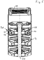
- the sensor housing 9e is also firmly connected to the last stage of the centrifugal pump 4, but there is the pump impeller 16 mounted within the sensor housing 9e freely rotatable, ie as a passive pump impeller similar to the arrangement according to Fig. 3 educated. Again, the power supply of the sensor via magnets 17 on the underside of the pump impeller 16, which cooperate with arranged within the liquid-free housing part 13 coils.
- a multi-stage centrifugal pump 4 In the illustration according to Fig. 7 the upper end of a multi-stage centrifugal pump 4 is shown on the left, the lower end connects to the engine part 3, which is shown on the right. Through the housing part performs a common shaft 20, which continues in the engine part 3.
- the attached at the upper end of the pump 4 sensor housing 9 f corresponds substantially to the basis of Fig. 3 provided and explained. However, here is a signal transmission from the liquid-free housing part 13 out through the liquid through to the shaft 20 by mechanical waves.
- an electroacoustic transducer is provided within the liquid-free housing part 13 of the sensor housing 9f, which converts the sensor signals into ultrasonic signals, which are transmitted via the liquid to the shaft 20.
- an acoustoelectric transducer 21 At the motor end of the shaft 20, an acoustoelectric transducer 21 is provided, which converts these mechanical vibrations back into an electrical signal, which is then passed through the supply cable 7 of the motor to the supply and control housing
- the shaft 20 is guided into the sensor housing 9 g, on which a pump impeller 16th the above-described training according to Fig. 3 .rius.
- This pump impeller 16 is thus actively driven by the shaft 20.
Landscapes
- Engineering & Computer Science (AREA)
- Mining & Mineral Resources (AREA)
- Geology (AREA)
- Life Sciences & Earth Sciences (AREA)
- Physics & Mathematics (AREA)
- Environmental & Geological Engineering (AREA)
- Fluid Mechanics (AREA)
- General Life Sciences & Earth Sciences (AREA)
- Geochemistry & Mineralogy (AREA)
- Mechanical Engineering (AREA)
- General Engineering & Computer Science (AREA)
- Geophysics (AREA)
- Structures Of Non-Positive Displacement Pumps (AREA)
- Control Of Non-Positive-Displacement Pumps (AREA)
Description
Die Erfindung betrifft eine Bohrlochpume gemäß den im Oberbegriff des Anspruchs 1 angegebenen Merkmalen.The invention relates to a borehole pump according to the features specified in the preamble of
Bei Tauchpumpen zählt es heutzutage zum Stand der Technik, diese mit einem Frequenzumrichter anzusteuern, sie weisen somit in der Regel eine Motorelektronik auf, die es erforderlich oder zumindest zweckmä-ßig erscheinen lässt, wesentliche Betriebsgrößen der Pumpe zu erfassen und bei der Ansteuerung zu berücksichtigen und ggf. zu verarbeiten. Hierzu zählen beispielsweise die Wicklungstemperatur des Motors, die Temperatur des zu fördernden Mediums, der Förderdruck, der Umgebungsdruck und dergleichen. Zur Erfassung dieser Größen wird entsprechende Sensorik in die Tauchpumpen integriert. Aus
Aus
Die Anordnung derartiger Sensoren in Tauchpumpen ist aufwendig, da einerseits eine Datenverbindung zu der Steuer- und Regelelektronik des Motors bestehen muss, andererseits eine elektrische Versorgung erforderlich ist und schließlich eine zuverlässige Abdichtung gegenüber dem Fördermedium gewährleistet sein muss. Allerdings bereitet bei Tauchpumpen der vorgenannten Art (Schmutzwasserpumpen) die Sensoranordnung konstruktiv weniger Probleme, da der Bauraum der Pumpe vergleichsweise groß ist und die Sensorik in der Regel an geeigneter Stelle innerhalb des Pumpengehäuses eingegliedert werden kann, ohne dass hierzu wesentliche konstruktive Änderungen des Pumpenaggregats selbst erforderlich sind. Anders ist dies hingegen bei Bohrlochpumpen, bei denen der Bauraum insbesondere in radialer Richtung eng begrenzt ist und bei denen nach Möglichkeit ein modulartiger Aufbau zum Vorsehen verschiedener Anzahl von Pumpenstufen gegeben sein sollte. Bei Bohrlochpumpen stellt dies also ein räumliches Problem dar, weshalb man bisher auf den Einbau solcher Sensorik entweder verzichtet hat oder einen enormen Bauaufwand kalkulieren musste.The arrangement of such sensors in submersible pumps is expensive because on the one hand must be a data connection to the control electronics of the engine, on the other hand an electrical supply is required and finally a reliable seal against the fluid must be guaranteed. However, prepares for submersible pumps the aforementioned type (dirty water pumps) the sensor assembly constructively fewer problems, since the space of the pump is comparatively large and the sensor can be incorporated usually at a suitable location within the pump housing, without that this essential structural changes of the pump unit itself are required. By contrast, this is different in borehole pumps, in which the space is particularly limited, especially in the radial direction and in which, if possible, a modular design should be given to provide different number of pump stages. In the case of borehole pumps, this therefore represents a spatial problem, which is why it has hitherto either dispensed with the installation of such sensors or had to calculate an enormous amount of construction work.
Vor diesem Hintergrund liegt der Erfindung die Aufgabe zugrunde, eine gattungsgemäße Bohrlochpumpe so auszubilden, dass ein oder mehrere Sensoren kostengünstig an geeigneter Stelle angeordnet und entsprechend signal- bzw. datenverbunden werden können.Against this background, the invention has the object, a generic borehole pump in such a way that one or more sensors can be arranged inexpensively at a suitable location and corresponding signal or data connected.
Diese Aufgabe wird gemäß der Erfindung durch die in Anspruch 1 angegebenen Merkmale gelöst. Vorteilhafte Ausgestaltungen der Erfindung ergeben sich aus den Unteransprüchen, der nachfolgenden Beschreibung und der Zeichnung.This object is achieved according to the invention by the features specified in
Die erfindungsgemäße Bohrlochpumpe weist einen elektrischen Antriebsmotor und eine davon angetriebene ein- oder mehrstufige Kreiselpumpe auf. Gemäß der Erfindung sind ein oder mehrere Sensoren der Pumpe in einem Sensorgehäuse angeordnet, welches, flüssigkeitsdurchströmt ist und flüssigkeitsumgeben ist. Das Sensorgehäuse ist zwischen Motor und Pumpe, am Ende der Pumpe oder innerhalb der Pumpe angeordnet. Dabei kann das Sensorgehäuse entweder als gesondertes Gehäuse am Ende Pumpe angeordnet sein oder auch Teil des Pumpengehäuses bilden, also integral mit diesem ausgebildet sein.The borehole pump according to the invention has an electric drive motor and a single-stage or multi-stage centrifugal pump driven by it. According to the invention, one or more sensors of the pump are arranged in a sensor housing, which, liquid flows through and liquid surrounds. The sensor housing is located between the motor and the pump, at the end of the pump or inside the pump. In this case, the sensor housing can either be arranged as a separate housing at the end of the pump or form part of the pump housing, so be formed integrally with this.
Grundgedanke der vorliegenden Erfindung ist es, nach Möglichkeit die komplette Sensorik, zumindest jedoch einen oder mehrere Sensoren in einem gesonderten Sensorgehäuse unterzubringen, welches am Ende der Pumpe, innerhalb der Pumpe oder zwischen Motor und Pumpe, also am anderen Ende der Pumpe angeordnet ist. Dieses Sensorgehäuse kann modulartig ausgebildet sein, sodass es ggf. auch bei vorhandenen Pumpen nachgerüstet werden kann oder zumindest Pumpen der gleichen Serie mit oder ohne Sensorgehäuse ausgestattet werden können, also mit und ohne Sensorik ausgeliefert können. Da das Sensorgehäuse zwischen Motor und Pumpe, innerhalb der Pumpe oder am Ende der Pumpe angeordnet ist, wird die Bohrlochpumpe hierdurch in ihrer Außenkontur nicht verändert, sondern lediglich in ihrer Länge, was für Bohrlochpumpen besonders wichtig ist. Da die Sensorik typischerweise mit dem Förderstrom der Pumpe einerseits und dem umgebenden Medium andererseits in Verbindung steht, ist das erfindungsgemä-ße Sensorgehäuse so ausgebildet und angeordnet, dass es einerseits flüssigkeitsdurchströmt und andererseits von Flüssigkeit umgeben ist. So können beispielsweise Temperaturen und/oder Druck sowohl vom umgebenden als auch vom geförderten Fluid erfasst werden. Da nach Möglichkeit die gesamte Sensorik oder zumindest ein Großteil innerhalb des Sensorgehäuses angeordnet ist, braucht wenn überhaupt, nur dieses Sensorgehäuse mit einem nach außen geführten Kabel versehen zu sein, was bei Bohrlochpumpen von Vorteil ist, wenn das Sensorgehäuse am oberen Ende der Pumpe angeordnet ist, an welchem ohnehin nur das Netzkabel neben der Förderleitung verläuft. Bei der Anordnung zwischen Motor und Pumpe ergibt sich der Vorteil, dass die Verkabelung über den Motor erfolgen kann, der ohnehin eine Kabelführung nach außen zur elektrischen Stromversorgung und ggf. auch zur Steuer- und Regelelektronik benötigt.The basic idea of the present invention is, if possible, to accommodate the complete sensor system, but at least one or more sensors in a separate sensor housing, which at the end the pump, within the pump or between the motor and the pump, that is arranged at the other end of the pump. This sensor housing may have a modular design, so that it can optionally be retrofitted to existing pumps or at least pumps of the same series can be equipped with or without sensor housing, so can be shipped with and without sensors. Since the sensor housing is arranged between the motor and pump, within the pump or at the end of the pump, the borehole pump is thereby not changed in its outer contour, but only in their length, which is particularly important for borehole pumps. Since the sensor typically communicates with the flow of the pump on the one hand and the surrounding medium on the other hand, the sensor housing according to the invention is designed and arranged in such a way that liquid flows through it and liquid is surrounded on the one hand. For example, temperatures and / or pressure can be detected by both the surrounding and the delivered fluid. Since, if possible, the entire sensor system or at least a large part is arranged inside the sensor housing, only that sensor housing needs to be provided with an outwardly directed cable, which is an advantage in borehole pumps when the sensor housing is arranged at the upper end of the pump on which anyway only the power cable runs next to the conveyor line. In the arrangement between the motor and pump, there is the advantage that the wiring can be done via the motor, which anyway requires a cable to the outside to the electrical power supply and possibly also to the control electronics.
Dabei ist das Sensorgehäuse in einen flüssigkeitsführenden Gehäuseteil und einen flüssigkeitsfreien Gehäuseteil aufgeteilt, die durch eine vorzugsweise durch Edelstahlblech gebildete Gehäusewand voneinander getrennt sind. Eine solche Gehäusewand kann nach Art eines Spaltrohres vergleichsweise dünn aber absolut flüssigkeitsdicht ausgebildet sein, sodass mit Ausnahme der Druck- und/oder Differenzdrucksensoren ggf. auch durch die Gehäusewand hindurch gemessen werden kann, beispielsweise Temperatur, Vibration und dergleichen. Dies hat den erheblichen Vorteil, dass die hoch feuchtigkeitsempfindliche Elektronik und Sensorik in einem zuverlässig flüssigkeitsfreien Gehäuseteil angeordnet werden kann, wohingegen durch die Gehäusewand praktisch auch Zugriff auf das Fördermedium und/oder das umgebende Medium besteht.In this case, the sensor housing is divided into a liquid-conducting housing part and a liquid-free housing part, which are separated by a preferably formed by stainless steel sheet housing wall. Such a housing wall may be formed in the manner of a split tube comparatively thin but absolutely liquid-tight, so that, with the exception of the pressure and / or differential pressure sensors, if necessary, it is also possible to measure through the housing wall, for example temperature, vibration and the like. This has the considerable advantage that the highly moisture-sensitive electronics and sensors can be arranged in a reliable liquid-free housing part, whereas practically by the housing wall access to the pumped medium and / or the surrounding medium.
Zweckmäßigerweise wird nicht nur ein Teilstrom sondern der gesamte Förderstrom der Pumpe durch das flüssigkeitsführende Gehäuseteil geleitet, wobei das Gehäuseteil so ausgebildet ist, dass es quasi eine weitere Pumpenstufe oder eine Rohrverlängerung darstellt, also möglichst wenig Strömungswiderstand bietet. Die im Sensorgehäuse befindliche Sensorik und ggf. Elektronik benötigt vergleichsweise wenig Platz, sodass ein kleiner umlaufender Freiraum in der Regel ausreicht, um diese Bauelemente unterzubringen.Conveniently, not only a partial flow but the entire flow of the pump is passed through the liquid-carrying housing part, wherein the housing part is formed so that it is almost a further pump stage or a pipe extension, that provides as little flow resistance. The sensors located in the sensor housing and possibly electronics requires comparatively little space, so that a small circumferential free space is usually sufficient to accommodate these components.
Gemäß der Erfindung ist es vorgesehen, die elektrische Energie, die erforderlich ist, um die im Sensorgehäuse angeordneten Sensoren zu betreiben und ggf. die davon ausgehenden elektrischen Signale aufzubereiten, weiterzuverarbeiten und in digitale Daten umzusetzen, unmittelbar innerhalb des Sensorgehäuses zu erzeugen, um damit auf eine Leitung zur Stromversorgung des Sensorgehäuses völlig verzichten zu können. Hierzu ist gemäß der Erfindung im Sensorgehäuse eine Induktionsanordnung vorgesehen, mit der beim Betrieb der Pumpe elektrische Energie erzeugt wird.According to the invention, it is provided that the electrical energy required to operate the sensors arranged in the sensor housing and, if necessary, reprocess the electrical signals emanating therefrom, process them and convert them into digital data, can be generated directly within the sensor housing in order to be present completely dispense with a line for powering the sensor housing. For this purpose, according to the invention, an induction arrangement is provided in the sensor housing, with which electrical energy is generated during operation of the pump.
Dazu weist die Induktionsanordnung mindestens einen im flüssigkeitsführenden Gehäuseteil rotierbar angeordneten Magneten auf und mindestens eine im flüssigkeitsfreien Gehäuseteil angeordnete Induktionsspule auf, derart, dass durch den sich an der Spule vorbei bewegenden Magneten ein Strom in der Spule induziert wird, der für die vorgenannten Zwecke nutzbar ist. Zweckmäßigerweise werden zwei oder mehr Magneten angeordnet sein, die mit ggf. mehreren Induktionsspulen zusammenwirken und somit eine Art elektrischen Generator bilden.For this purpose, the induction arrangement has at least one magnet rotatably arranged in the liquid-conducting housing part and at least one arranged in the liquid-free housing part induction coil, such that a current in the coil is induced by the magnet moving past the coil, which is usable for the aforementioned purposes , Conveniently, two or more magnets are arranged, which cooperate with possibly a plurality of induction coils and thus form a kind of electrical generator.
Um einen Antrieb für die Magneten zu bilden ist gemäß einer Weiterbildung der Erfindung vorgesehen, innerhalb des flüssigkeitsführenden Gehäuseteils ein Pumpenlaufrad drehbar zu lagern und so anzuordnen, dass es durch den Förderstrom der Pumpe in Rotation versetzt wird. Bei einer solchen Ausbildung ist das Sensorgehäuse quasi als weitere passive Pumpenstufe ausgebildet, der durchströmende Förderstrom treibt das darin angeordnete Pumpenlaufrad mit den daran befestigten Magneten, die dadurch in der oder den Spulen eine Spannung induzieren bzw. einen Strom erzeugen und somit die Sensorik innerhalb des Gehäuses mit Strom versorgen.In order to form a drive for the magnets is provided according to a development of the invention, rotatably support a pump impeller within the liquid-conducting housing part and to be arranged so that it is rotated by the flow rate of the pump in rotation. at Such a design, the sensor housing is quasi designed as a further passive pump stage, the flow passing through it drives the impeller mounted thereon with the magnets attached thereto, thereby inducing a voltage in the one or more coils or generate a current and thus the sensor within the housing Supply electricity.
Gemäß einer Weiterbildung der Erfindung kann ein solches passives Pumpenlaufrad, das innerhalb des Sensorgehäuses frei drehbar angeordnet ist, und an dem mindestens ein Magnet angeordnet ist, auch Teil eines Durchflussmessers bilden, wobei dann innerhalb des flüssigkeitsfreien Gehäuseteils ein induktiver Aufnehmer, beispielsweise eine Spule angeordnet ist, so dass die Drehzahl des Pumpenlaufrads erfasst werden kann und darüber die Durchflussmenge ermittelt werden kann. Es muss nicht zwingend notwendig ein Pumpenlaufrad drehbar angeordnet sein, es kann eine Art Flügel rotierbar angeordnet sein, an dessen Ende ein Magnet sitzt, welcher in Abhängigkeit der Strömungsmenge schneller oder langsamer rotiert.According to one embodiment of the invention, such a passive pump impeller, which is arranged freely rotatable within the sensor housing, and on which at least one magnet is arranged, also form part of a flow meter, wherein then within the liquid-free housing part, an inductive pickup, such as a coil is arranged , so that the speed of the pump impeller can be detected and above the flow rate can be determined. It does not necessarily have a pump impeller rotatably arranged, it can be arranged rotatably a kind of wing, at the end of a magnet sits, which rotates faster or slower depending on the flow rate.
Wenn hingegen das Sensorgehäuse mehr oder weniger integraler Bestandteil der Pumpe ist, also die Pumpe konstruktiv daran angepasst werden kann, dann kann statt eines passiven Laufrads vorteilhaft die Antriebswelle bis in das Sensorgehäuse hinein verlängert werden und dort mit einem Halter versehen werden, welcher den oder die Magneten trägt und der durch die Antriebwelle selbst rotiert wird, auch kann ein aktives Pumpenlaufrad vorgesehen sein, das Magneten trägt.If, however, the sensor housing is more or less an integral part of the pump, so the pump can be structurally adapted thereto, then instead of a passive impeller advantageously the drive shaft can be extended into the sensor housing inside and there are provided with a holder, which or the Magnets and is rotated by the drive shaft itself, also an active pump impeller may be provided which carries magnets.
Bei integraler Ausbildung des Sensorgehäuses im Pumpengehäuse kann prinzipiell beispielsweise bei einer mehrstufigen Bohrlochpumpe jede beliebige Pumpenstufe durch entsprechende Modifizierung als Sensorgehäuse ausgebildet werden. So ist es auch denkbar, nicht nur ein, sondern mehrere Sensorgehäuse vorzusehen, um beispielsweise den Druck jeder einzelnen Pumpenstufe überwachen zu können.In the case of integral design of the sensor housing in the pump housing, in principle, for example, in the case of a multi-stage borehole pump, any desired pump stage can be designed as a sensor housing by appropriate modification. So it is also conceivable, not just one, but to provide a plurality of sensor housing to monitor, for example, the pressure of each pump stage.
Da durch die vorgenannten konstruktiven Maßnahmen auf eine elektrische Stromversorgung des Sensorgehäuses von außen verzichtet werden kann, ist es besonders zweckmäßig, auch die aus dem Sensorgehäuse herauszuführenden elektrischen Signale und/oder Sensordaten kabellos herauszuführen.Since it is possible to dispense with an electrical power supply of the sensor housing from the outside by the above-mentioned constructive measures, it is particularly expedient to wirelessly lead out also the electrical signals and / or sensor data to be led out of the sensor housing.
Da zum Motor hin ohnehin ein elektrisches Versorgungskabel liegt, kann dieses durch entsprechende Ausgestaltung in einfacher Weise auch zur Datenübertragung genutzt werden, sei es durch Aufmodulieren des Signals oder durch Vorsehen eines weiteren Leiters. Dann ist es zweckmäßig, die elektrischen Signale der Sensoren bzw. die daraus abgeleiteten Daten vom Sensorgehäuse in das Motorgehäuse zu übertragen. Dies erfolgt erfindungsgemäß mechanisch über die gemeinsame Welle. Hierzu kann im Bereich des Sensorgehäuses ein elektroakustischer Wandler vorgesehen sein, welcher das elektrische Signal in ein Schallsignal, typischerweise ein Ultraschallsignal umwandelt und direkt oder indirekt auf die Welle überträgt. Motorseitig ist dann ein akustoelektrischer Wandler vorzusehen, der dieses Signal wieder in ein elektrisches Signal umwandelt, das dann in geeigneter Weise herausgeführt wird.Since the motor is anyway an electrical supply cable, this can be used by appropriate design in a simple manner for data transmission, either by modulating the signal or by providing a further conductor. It is then expedient to transmit the electrical signals of the sensors or the data derived therefrom from the sensor housing into the motor housing. This is done according to the invention mechanically via the common shaft. For this purpose, in the region of the sensor housing, an electroacoustic transducer can be provided, which converts the electrical signal into a sound signal, typically an ultrasonic signal, and transmits it directly or indirectly to the shaft. On the motor side, an acoustoelectric transducer is then provided, which converts this signal back into an electrical signal, which is then led out in a suitable manner.
Innerhalb des Sensorgehäuses können unterschiedlichste Sensoren angeordnet sein, typischerweise ein oder mehrere Temperatursensoren zur Erfassung der Temperatur des Förderstroms und/oder des umgebenden Mediums, ein Vibrationssensor zur Erfassung mechanischer Schwingungen, ein Druck- oder Differenzdrucksensor zur Erfassung des Umgebungsdrucks und/oder des Förderdrucks. Diese Aufzählung ist nur beispielhaft und kann durch beliebige weitere Sensoren ergänzt werden.Within the sensor housing a variety of sensors may be arranged, typically one or more temperature sensors for detecting the temperature of the flow and / or the surrounding medium, a vibration sensor for detecting mechanical vibrations, a pressure or differential pressure sensor for detecting the ambient pressure and / or the delivery pressure. This list is only an example and can be supplemented by any other sensors.
Besonders vorteilhaft werden zumindest die Sensoren, die nicht zwingend mit der umgebenden oder geförderten Flüssigkeit in Verbindung stehen müssen, wie z. B. der Druck- oder Differenzdrucksensor, in dem flüssigkeitsfreien Gehäuseteil angeordnet. So kann bei geeigneter Ausbildung der Gehäusewand der Temperatursensor durch die Gehäusewand von der Flüssigkeit getrennt angeordnet werden, ebenso der Vibrationssensor, was ersichtlich Vorteile mit sich bringt.Particularly advantageous are at least the sensors, which need not necessarily be in communication with the surrounding or conveyed liquid, such. B. the pressure or differential pressure sensor, arranged in the liquid-free housing part. Thus, with suitable design of the housing wall of the temperature sensor can be separated by the housing wall of the liquid, as well as the vibration sensor, which brings obvious benefits.
Die Erfindung ist nachfolgend anhand von in der Zeichnung dargestellten Ausführungsbeispielen näher erläutert. Es zeigen:
- Fig. 1
- in stark vereinfachter schematischer Darstellung die Anordnung einer Bohrlochpumpe in einem Bohrloch,
- Fig. 2
- eine nicht zur Erfindung gehörende erste Ausführung eines Sensorgehäuses im Schnitt,
- Fig. 3
- eine zweite nicht zur Erfindung gehörende Ausführung eines Sensorgehäuses im Schnitt,
- Fig. 4
- eine dritte nicht zur Erfindung gehörende Ausführung eines Sensorgehäuses im Schnitt,
- Fig. 5
- den oberen Teil einer Bohrlochpumpe mit integriertem Sensorgehäuse im Schnitt,
- Fig. 6
- eine alternative Bauform mit im Pumpengehäuse integriertem Sensorgehäuse im Schnitt,
- Fig. 7
- eine erste Ausführung einer Bohrlochpumpe mit mechanischer Signalübertragung vom Sensorgehäuse zum Motorgehäuse in Schnittdarstellung und
- Fig. 8
- eine weitere Ausführung in Darstellung nach
Fig. 7
- Fig. 1
- in a highly simplified schematic representation of the arrangement of a borehole pump in a borehole,
- Fig. 2
- a not belonging to the invention first embodiment of a sensor housing in section,
- Fig. 3
- a second not belonging to the invention embodiment of a sensor housing in section,
- Fig. 4
- a third not belonging to the invention embodiment of a sensor housing in section,
- Fig. 5
- the upper part of a borehole pump with integrated sensor housing in section,
- Fig. 6
- an alternative design with integrated housing in the pump housing in section,
- Fig. 7
- a first embodiment of a borehole pump with mechanical signal transmission from the sensor housing to the motor housing in a sectional view and
- Fig. 8
- another embodiment in illustration after
Fig. 7
Die anhand von
Der Motor 3 wird über ein Kabel 7 versorgt, das im Bereich der Kreiselpumpe 4 an der Außenseite lang geführt ist und neben der Druckleitung 6 verläuft bis zu einem Versorgungs- und Steuergehäuse 8, über den der Motor stromversorgt wird. Innerhalb des Steuergehäuses 8 kann beispielsweise ein Frequenzumrichter vorgesehen sein, sowie sämtliche Mittel zum Steuern und Überwachen der Pumpe. Zwischen dem oberen Ende der Kreiselpumpe und dem unteren Ende der Druckleitung 6 ist ein Sensorgehäuse 9 angeordnet, dessen Aufbau beispielhaft im Folgenden erläutert ist.The
Das in
Das Sensorgehäuse 9a weist einen flüssigkeitsführenden inneren Gehäuseteil 12 und einen flüssigkeitsfreien äußeren Gehäuseteil 13 auf, die durch eine spaltrohrähnliche dünne Wandung 14 voneinander getrennt sind. Der flüssigkeitsführende Gehäuseteil 12 ist im Wesentlichen rohrförmig ausgebildet und setzt den Querschnitt der Druckleitung 6 erweiternd fort, um dann wieder in den Gewindestutzen 10 überzugehen. In dem erweiterten Bereich ist der flüssigkeitsfreie Gehäuseteil 13 angeordnet, der einen umlaufenden ringförmigen Raum bildet, in dem Sensoren, nämlich ein Temperatursensor an der Wandung 14 anliegend zur Erfassung der Temperatur des Fördermediums, ein Drucksensor, die Wandung 14 durchdringend zur Erfassung des Drucks der Förderflüssigkeit, ein Drucksensor die Außenwandung durchdringend zur Erfassung des Umgebungsdrucks und ein Vibrationssensor angeordnet sind. Weiterhin ist innerhalb dieses flüssigkeitsfreien Gehäuseteils 13 die zur Aufbereitung der von den Sensoren abgegebenen elektrischen Signale erforderliche Elektronik vorgesehen. Die Stromversorgung der innerhalb des Sensorgehäuses 9a befindlichen Sensorik erfolgt über ein Kabel 15, über welches auch die elektrischen Signale der Sensoren herausgeführt werden. Das Kabel 15 kann mit dem Kabel 7 zusammengeführt sein oder parallel dazu laufen.The sensor housing 9a has a liquid-conducting
Das anhand der
Bei der anhand von
Anhand der
Bei der Ausführungsvariante gemäß
In der Darstellung gemäß
Bei der anhand von
- 11
- - Bohrlochpumpe- Borehole pump
- 22
- - Bohrloch- borehole
- 33
- - Motorteil- Engine part
- 44
- - Kreiselpumpe- Centrifugal pump
- 55
- - Ansaugöffnungen- Intake openings
- 66
- - Druckleitung- pressure line
- 77
- - Kabel- Electric wire
- 88th
- - Versorgungs- und Steuergehäuse- Supply and control housing
- 99
-
- Sensorgehäuse in
Fig. 1 - Sensor housing inFig. 1 - 9a9a
-
- Sensorgehäuse in
Fig. 2 - Sensor housing inFig. 2 - 9b9b
-
- Sensorgehäuse in
Fig. 3 - Sensor housing inFig. 3 - 9c9c
-
- Sensorgehäuse in
Fig. 4 - Sensor housing inFig. 4 - 9d9d
-
- Sensorgehäuse in
Fig. 5 - Sensor housing inFig. 5 - 9e9e
-
- Sensorgehäuse in
Fig. 6 - Sensor housing inFig. 6 - 9f9f
-
- Sensorgehäuse in
Fig. 7 - Sensor housing inFig. 7 - 9g9g
-
- Sensorgehäuse in
Fig. 8 - Sensor housing inFig. 8 - 1010
- - Gewindestutzen- threaded connector
- 1111
- - Innengewinde- Inner thread
- 1212
- - flüssigkeitsführender Gehäuseteil- liquid-carrying housing part
- 1313
- - flüssigkeitsfreier Gehäuseteil- liquid-free housing part
- 1414
- - Wandung- wall
- 1515
- - Kabel- Electric wire
- 1616
- - Pumpenlaufrad- Pump impeller
- 1717
- - Magneten- magnets
- 1818
- - Spulen- Do the washing up
- 1919
- - Flügel- wings
- 2020
- - Welle- Wave
- 2121
- - akustoelektrischer Wandler- acoustoelectric converter
Claims (2)
- A bore-hole pump (1) with an electrical drive motor (3) and with a single-stage or multi-stage centrifugal pump (4) which is driven by this motor and which has one or more sensors, said sensors are arranged in a sensor housing (9) through which fluid flows, which is surrounded by fluid and which comprises a fluid-leading housing part (12) and a fluid-free housing part (13), said housing parts being separated from one another by a housing wall (14) which is arranged between the motor (3) and the pump (4), at the end of the pump (4) or within the pump (4), wherein an induction arrangement (17, 18) is provided in the sensor housing (9), with which arrangement electrical energy is produced on operation of the pump (4), characterised in that the induction arrangement (17, 18) comprises at least one magnet (17) which is rotatably arranged in the fluid-leading housing part (12), and that at least one induction coil (18) is arranged in the fluid-free housing part and that means (20, 21) for the signal transmission and/or data transmission from the sensor housing (9) to the motor housing are provided, wherein the signal transmission and/or data transmission is effected mechanically by the shaft (20) and, for this, an electro-acoustic transducer acting upon the shaft (20) is provided at the sensor housing side and an acousto-electrical transducer (21) is provided at the motor side.
- A bore-hole pump (1) according to one of the preceding claims, characterised in that the sensor housing (9) comprises a temperature sensor, a vibration sensor, a flow sensor and/or a pressure sensor or differential pressure sensor.
Priority Applications (3)
| Application Number | Priority Date | Filing Date | Title |
|---|---|---|---|
| EP07024940.4A EP2072829B2 (en) | 2007-12-21 | 2007-12-21 | Immersion pump |
| US12/339,201 US8454330B2 (en) | 2007-12-21 | 2008-12-19 | Submersible pump |
| CN2008101853538A CN101487473B (en) | 2007-12-21 | 2008-12-22 | Submersible pump |
Applications Claiming Priority (1)
| Application Number | Priority Date | Filing Date | Title |
|---|---|---|---|
| EP07024940.4A EP2072829B2 (en) | 2007-12-21 | 2007-12-21 | Immersion pump |
Publications (3)
| Publication Number | Publication Date |
|---|---|
| EP2072829A1 EP2072829A1 (en) | 2009-06-24 |
| EP2072829B1 EP2072829B1 (en) | 2014-12-17 |
| EP2072829B2 true EP2072829B2 (en) | 2017-12-20 |
Family
ID=39477558
Family Applications (1)
| Application Number | Title | Priority Date | Filing Date |
|---|---|---|---|
| EP07024940.4A Not-in-force EP2072829B2 (en) | 2007-12-21 | 2007-12-21 | Immersion pump |
Country Status (3)
| Country | Link |
|---|---|
| US (1) | US8454330B2 (en) |
| EP (1) | EP2072829B2 (en) |
| CN (1) | CN101487473B (en) |
Families Citing this family (19)
| Publication number | Priority date | Publication date | Assignee | Title |
|---|---|---|---|---|
| EP2309133B1 (en) * | 2009-10-05 | 2015-07-15 | Grundfos Management A/S | Submersible pump power unit |
| US8347953B1 (en) * | 2009-12-11 | 2013-01-08 | Ge Oil & Gas Esp, Inc. | Inline monitoring package for electrical submersible pump |
| CN101915243B (en) * | 2010-07-09 | 2012-07-11 | 美的集团有限公司 | Evacuation device and control method of cooling fan submersible pump |
| US8727737B2 (en) * | 2010-10-22 | 2014-05-20 | Grundfos Pumps Corporation | Submersible pump system |
| US9121270B2 (en) | 2011-05-26 | 2015-09-01 | Grundfos Pumps Corporation | Pump system |
| DE102012200806B4 (en) * | 2012-01-20 | 2014-07-31 | Yasa Motors Poland Sp. z.o.o. | Wet runner pump with power electronics |
| GB2515263B (en) * | 2013-04-26 | 2015-09-09 | Rotech Group Ltd | Improved turbine |
| BR112016022984B1 (en) | 2014-04-03 | 2022-08-02 | Schlumberger Technology B.V. | METHOD FOR EVALUATION OF AN OPERATION OF A PUMPING SYSTEM, METHOD, AND METHOD FOR IMPROVING A LIFE EXPECTATION OF A PUMPING SYSTEM |
| CN104165135B (en) * | 2014-07-08 | 2016-03-09 | 中国石油天然气集团公司 | Oiling Quick Connect Kit exempted from by submersible electric pump sensor |
| DK3184823T3 (en) * | 2015-12-21 | 2019-07-08 | Grundfos Holding As | Centrifugal |
| WO2018022198A1 (en) * | 2016-07-26 | 2018-02-01 | Schlumberger Technology Corporation | Integrated electric submersible pumping system with electromagnetically driven impeller |
| EP3563062B1 (en) * | 2016-12-30 | 2021-07-21 | Grundfos Holding A/S | Sensor assembly and method for fault detection in pumps and pump assembly comprising such sensor assembly |
| US10876534B2 (en) * | 2017-08-01 | 2020-12-29 | Baker Hughes, A Ge Company, Llc | Combined pump and motor with a stator forming a cavity which houses an impeller between upper and lower diffusers with the impeller having a circumferential magnet array extending upward and downward into diffuser annular clearances |
| DK3546760T3 (en) * | 2018-03-26 | 2020-09-28 | Xylem Europe Gmbh | Submersible drainage sump pump |
| US12025136B2 (en) | 2019-03-26 | 2024-07-02 | Schlumberger Technology Corporation | Electrical submersible pumping systems |
| EP3744981B1 (en) * | 2019-05-28 | 2024-08-07 | Grundfos Holding A/S | Submersible pump assembly and method for operating the submersible pump assembly |
| DE102019004263A1 (en) * | 2019-06-18 | 2020-12-24 | KSB SE & Co. KGaA | Centrifugal pump and method for detecting the status of a centrifugal pump |
| US12258970B2 (en) | 2021-05-12 | 2025-03-25 | Grundfos Holding A/S | Centrifugal pump |
| CN115788919A (en) | 2021-09-09 | 2023-03-14 | 创科无线普通合伙 | submersible pump |
Citations (7)
| Publication number | Priority date | Publication date | Assignee | Title |
|---|---|---|---|---|
| EP0033192A1 (en) † | 1980-01-21 | 1981-08-05 | Sperry Corporation | A system for the acoustic propagation of data along a borehole drilling string |
| DE4013978A1 (en) † | 1990-05-01 | 1991-11-07 | Innotech Microelectronik Gmbh | Data transmission system using ultrasound - transmits information via machine bearing to stationary target, for registration or regulation |
| US5148408A (en) † | 1990-11-05 | 1992-09-15 | Teleco Oilfield Services Inc. | Acoustic data transmission method |
| DE19728392A1 (en) † | 1997-07-03 | 1999-01-07 | Mantel Juval | Fluid flow meter for gas or liquid, e.g. water meter in large building |
| JP2006170903A (en) † | 2004-12-17 | 2006-06-29 | Shin Nippon Air Technol Co Ltd | Flowmeter with power generator |
| RU2285155C1 (en) † | 2005-09-16 | 2006-10-10 | Михаил Яковлевич Либкин | Oil-well pumping unit |
| US20070114040A1 (en) † | 2005-11-22 | 2007-05-24 | Schlumberger Technology Corporation | System and Method for Sensing Parameters in a Wellbore |
Family Cites Families (11)
| Publication number | Priority date | Publication date | Assignee | Title |
|---|---|---|---|---|
| US2550667A (en) * | 1944-08-01 | 1951-05-01 | Byron Jackson Co | Seal structure |
| US3021788A (en) | 1957-05-02 | 1962-02-20 | American Crucible Products Com | Submersible pump |
| US2969740A (en) | 1957-05-27 | 1961-01-31 | American Crucible Products Com | Pump control |
| US3867655A (en) * | 1973-11-21 | 1975-02-18 | Entropy Ltd | Shaftless energy conversion device |
| US6811382B2 (en) * | 2000-10-18 | 2004-11-02 | Schlumberger Technology Corporation | Integrated pumping system for use in pumping a variety of fluids |
| US6612188B2 (en) * | 2001-01-03 | 2003-09-02 | Neptune Technology Group Inc. | Self-powered fluid meter |
| SE0104317L (en) | 2001-12-20 | 2002-11-26 | Itt Mfg Enterprises Inc | Liquid flow sensing device in a pump outlet intended to control the power supply to the electrically driven pump motor |
| US6695052B2 (en) * | 2002-01-08 | 2004-02-24 | Schlumberger Technology Corporation | Technique for sensing flow related parameters when using an electric submersible pumping system to produce a desired fluid |
| FI20041480A0 (en) * | 2004-11-17 | 2004-11-17 | Pom Technology Oy Ab | Exhaust gas centrifugal device with sensor |
| US7571770B2 (en) * | 2005-03-23 | 2009-08-11 | Baker Hughes Incorporated | Downhole cooling based on thermo-tunneling of electrons |
| US7277026B2 (en) * | 2005-05-21 | 2007-10-02 | Hall David R | Downhole component with multiple transmission elements |
-
2007
- 2007-12-21 EP EP07024940.4A patent/EP2072829B2/en not_active Not-in-force
-
2008
- 2008-12-19 US US12/339,201 patent/US8454330B2/en not_active Expired - Fee Related
- 2008-12-22 CN CN2008101853538A patent/CN101487473B/en not_active Expired - Fee Related
Patent Citations (7)
| Publication number | Priority date | Publication date | Assignee | Title |
|---|---|---|---|---|
| EP0033192A1 (en) † | 1980-01-21 | 1981-08-05 | Sperry Corporation | A system for the acoustic propagation of data along a borehole drilling string |
| DE4013978A1 (en) † | 1990-05-01 | 1991-11-07 | Innotech Microelectronik Gmbh | Data transmission system using ultrasound - transmits information via machine bearing to stationary target, for registration or regulation |
| US5148408A (en) † | 1990-11-05 | 1992-09-15 | Teleco Oilfield Services Inc. | Acoustic data transmission method |
| DE19728392A1 (en) † | 1997-07-03 | 1999-01-07 | Mantel Juval | Fluid flow meter for gas or liquid, e.g. water meter in large building |
| JP2006170903A (en) † | 2004-12-17 | 2006-06-29 | Shin Nippon Air Technol Co Ltd | Flowmeter with power generator |
| RU2285155C1 (en) † | 2005-09-16 | 2006-10-10 | Михаил Яковлевич Либкин | Oil-well pumping unit |
| US20070114040A1 (en) † | 2005-11-22 | 2007-05-24 | Schlumberger Technology Corporation | System and Method for Sensing Parameters in a Wellbore |
Also Published As
| Publication number | Publication date |
|---|---|
| US20090162223A1 (en) | 2009-06-25 |
| EP2072829A1 (en) | 2009-06-24 |
| EP2072829B1 (en) | 2014-12-17 |
| CN101487473B (en) | 2011-12-07 |
| CN101487473A (en) | 2009-07-22 |
| US8454330B2 (en) | 2013-06-04 |
Similar Documents
| Publication | Publication Date | Title |
|---|---|---|
| EP2072829B2 (en) | Immersion pump | |
| EP1564411A1 (en) | Method for detecting operation errors of a pump aggregate | |
| EP3138791B1 (en) | Drum motor and sensor cartridge for a drum motor | |
| DE69106120T2 (en) | DEVICE FOR MEASURING THE POSITION CHANGE OF A ROTOR. | |
| EP2258949B1 (en) | Method for recording characteristic values, in particular values, in particular of parameters of a centrifugal pump powered by an electric motor integrated into an assembly | |
| EP0232891A2 (en) | Drilling tool for deep wells | |
| DE102009022107A1 (en) | Method and device for determining the operating point of a work machine | |
| EP3315784B1 (en) | Submersible pump unit and method of operating a submersible pump unit | |
| DE102010037379A1 (en) | Pump arrangement with integrated vibration measurement | |
| DE3820003A1 (en) | SUBMERSIBLE PUMP UNIT | |
| EP3527829B1 (en) | Pump system and pump control method | |
| DE102009001353A1 (en) | Electric machine i.e. permanent magnet-excited synchronous machine, has sensor detecting rotational position of rotor and arranged on cover such that rotor hub or component torque-proofly connected with hub serve as sensor track of sensor | |
| WO2018050380A1 (en) | Machine with cooled hollow shaft and concentric rotary encoder | |
| WO2016166114A1 (en) | Pump and method for operating a pump for liquids | |
| EP3184823B1 (en) | Centrifugal pump | |
| DE102017001429A1 (en) | Electric machine with a device for cooling air guidance | |
| EP2154376A2 (en) | Noise reduction of electrically driven pumps | |
| DE10251496B4 (en) | Device for generating electrical energy and pressure pulses for signal transmission | |
| WO2004074691A1 (en) | Oscillation-optimised tubular pump | |
| DE102019130981A1 (en) | Eccentric screw pump | |
| DE102019118139A1 (en) | Rotary slide unit and method for monitoring the wear and tear of a slide in a rotary slide unit | |
| WO2012171792A1 (en) | Immersion pump and method for assembling an immersion pump | |
| DE102011082270B4 (en) | Storage device with a power generation unit | |
| DE102005042776A1 (en) | sensor arrangement | |
| EP4386150A1 (en) | Method for obtaining information in a waste water pump unit and/or a waste water pump system |
Legal Events
| Date | Code | Title | Description |
|---|---|---|---|
| PUAI | Public reference made under article 153(3) epc to a published international application that has entered the european phase |
Free format text: ORIGINAL CODE: 0009012 |
|
| AK | Designated contracting states |
Kind code of ref document: A1 Designated state(s): AT BE BG CH CY CZ DE DK EE ES FI FR GB GR HU IE IS IT LI LT LU LV MC MT NL PL PT RO SE SI SK TR |
|
| AX | Request for extension of the european patent |
Extension state: AL BA HR MK RS |
|
| 17P | Request for examination filed |
Effective date: 20091028 |
|
| 17Q | First examination report despatched |
Effective date: 20091125 |
|
| AKX | Designation fees paid |
Designated state(s): AT BE BG CH CY CZ DE DK EE ES FI FR GB GR HU IE IS IT LI LT LU LV MC MT NL PL PT RO SE SI SK TR |
|
| GRAP | Despatch of communication of intention to grant a patent |
Free format text: ORIGINAL CODE: EPIDOSNIGR1 |
|
| INTG | Intention to grant announced |
Effective date: 20140716 |
|
| GRAS | Grant fee paid |
Free format text: ORIGINAL CODE: EPIDOSNIGR3 |
|
| GRAA | (expected) grant |
Free format text: ORIGINAL CODE: 0009210 |
|
| AK | Designated contracting states |
Kind code of ref document: B1 Designated state(s): AT BE BG CH CY CZ DE DK EE ES FI FR GB GR HU IE IS IT LI LT LU LV MC MT NL PL PT RO SE SI SK TR |
|
| REG | Reference to a national code |
Ref country code: GB Ref legal event code: FG4D Free format text: NOT ENGLISH |
|
| REG | Reference to a national code |
Ref country code: CH Ref legal event code: EP |
|
| REG | Reference to a national code |
Ref country code: IE Ref legal event code: FG4D Free format text: LANGUAGE OF EP DOCUMENT: GERMAN |
|
| REG | Reference to a national code |
Ref country code: AT Ref legal event code: REF Ref document number: 702148 Country of ref document: AT Kind code of ref document: T Effective date: 20150115 |
|
| REG | Reference to a national code |
Ref country code: DE Ref legal event code: R096 Ref document number: 502007013627 Country of ref document: DE Effective date: 20150129 |
|
| PG25 | Lapsed in a contracting state [announced via postgrant information from national office to epo] |
Ref country code: LT Free format text: LAPSE BECAUSE OF FAILURE TO SUBMIT A TRANSLATION OF THE DESCRIPTION OR TO PAY THE FEE WITHIN THE PRESCRIBED TIME-LIMIT Effective date: 20141217 Ref country code: FI Free format text: LAPSE BECAUSE OF FAILURE TO SUBMIT A TRANSLATION OF THE DESCRIPTION OR TO PAY THE FEE WITHIN THE PRESCRIBED TIME-LIMIT Effective date: 20141217 |
|
| REG | Reference to a national code |
Ref country code: LT Ref legal event code: MG4D |
|
| PG25 | Lapsed in a contracting state [announced via postgrant information from national office to epo] |
Ref country code: LV Free format text: LAPSE BECAUSE OF FAILURE TO SUBMIT A TRANSLATION OF THE DESCRIPTION OR TO PAY THE FEE WITHIN THE PRESCRIBED TIME-LIMIT Effective date: 20141217 Ref country code: SE Free format text: LAPSE BECAUSE OF FAILURE TO SUBMIT A TRANSLATION OF THE DESCRIPTION OR TO PAY THE FEE WITHIN THE PRESCRIBED TIME-LIMIT Effective date: 20141217 Ref country code: GR Free format text: LAPSE BECAUSE OF FAILURE TO SUBMIT A TRANSLATION OF THE DESCRIPTION OR TO PAY THE FEE WITHIN THE PRESCRIBED TIME-LIMIT Effective date: 20150318 |
|
| PG25 | Lapsed in a contracting state [announced via postgrant information from national office to epo] |
Ref country code: BE Free format text: LAPSE BECAUSE OF NON-PAYMENT OF DUE FEES Effective date: 20141231 Ref country code: NL Free format text: LAPSE BECAUSE OF FAILURE TO SUBMIT A TRANSLATION OF THE DESCRIPTION OR TO PAY THE FEE WITHIN THE PRESCRIBED TIME-LIMIT Effective date: 20141217 |
|
| PG25 | Lapsed in a contracting state [announced via postgrant information from national office to epo] |
Ref country code: CZ Free format text: LAPSE BECAUSE OF FAILURE TO SUBMIT A TRANSLATION OF THE DESCRIPTION OR TO PAY THE FEE WITHIN THE PRESCRIBED TIME-LIMIT Effective date: 20141217 Ref country code: EE Free format text: LAPSE BECAUSE OF FAILURE TO SUBMIT A TRANSLATION OF THE DESCRIPTION OR TO PAY THE FEE WITHIN THE PRESCRIBED TIME-LIMIT Effective date: 20141217 Ref country code: SK Free format text: LAPSE BECAUSE OF FAILURE TO SUBMIT A TRANSLATION OF THE DESCRIPTION OR TO PAY THE FEE WITHIN THE PRESCRIBED TIME-LIMIT Effective date: 20141217 Ref country code: ES Free format text: LAPSE BECAUSE OF FAILURE TO SUBMIT A TRANSLATION OF THE DESCRIPTION OR TO PAY THE FEE WITHIN THE PRESCRIBED TIME-LIMIT Effective date: 20141217 Ref country code: RO Free format text: LAPSE BECAUSE OF FAILURE TO SUBMIT A TRANSLATION OF THE DESCRIPTION OR TO PAY THE FEE WITHIN THE PRESCRIBED TIME-LIMIT Effective date: 20141217 |
|
| REG | Reference to a national code |
Ref country code: CH Ref legal event code: PL |
|
| PG25 | Lapsed in a contracting state [announced via postgrant information from national office to epo] |
Ref country code: PL Free format text: LAPSE BECAUSE OF FAILURE TO SUBMIT A TRANSLATION OF THE DESCRIPTION OR TO PAY THE FEE WITHIN THE PRESCRIBED TIME-LIMIT Effective date: 20141217 Ref country code: IS Free format text: LAPSE BECAUSE OF FAILURE TO SUBMIT A TRANSLATION OF THE DESCRIPTION OR TO PAY THE FEE WITHIN THE PRESCRIBED TIME-LIMIT Effective date: 20150417 |
|
| REG | Reference to a national code |
Ref country code: DE Ref legal event code: R026 Ref document number: 502007013627 Country of ref document: DE |
|
| REG | Reference to a national code |
Ref country code: IE Ref legal event code: MM4A |
|
| PLBI | Opposition filed |
Free format text: ORIGINAL CODE: 0009260 |
|
| PG25 | Lapsed in a contracting state [announced via postgrant information from national office to epo] |
Ref country code: MC Free format text: LAPSE BECAUSE OF FAILURE TO SUBMIT A TRANSLATION OF THE DESCRIPTION OR TO PAY THE FEE WITHIN THE PRESCRIBED TIME-LIMIT Effective date: 20141217 |
|
| REG | Reference to a national code |
Ref country code: FR Ref legal event code: PLFP Year of fee payment: 9 |
|
| PLAX | Notice of opposition and request to file observation + time limit sent |
Free format text: ORIGINAL CODE: EPIDOSNOBS2 |
|
| 26 | Opposition filed |
Opponent name: KSB AKTIENGESELLSCHAFT Effective date: 20150916 |
|
| PG25 | Lapsed in a contracting state [announced via postgrant information from national office to epo] |
Ref country code: CH Free format text: LAPSE BECAUSE OF NON-PAYMENT OF DUE FEES Effective date: 20141231 Ref country code: IE Free format text: LAPSE BECAUSE OF NON-PAYMENT OF DUE FEES Effective date: 20141221 Ref country code: DK Free format text: LAPSE BECAUSE OF FAILURE TO SUBMIT A TRANSLATION OF THE DESCRIPTION OR TO PAY THE FEE WITHIN THE PRESCRIBED TIME-LIMIT Effective date: 20141217 Ref country code: LI Free format text: LAPSE BECAUSE OF NON-PAYMENT OF DUE FEES Effective date: 20141231 |
|
| REG | Reference to a national code |
Ref country code: AT Ref legal event code: MM01 Ref document number: 702148 Country of ref document: AT Kind code of ref document: T Effective date: 20141221 |
|
| PLBB | Reply of patent proprietor to notice(s) of opposition received |
Free format text: ORIGINAL CODE: EPIDOSNOBS3 |
|
| PG25 | Lapsed in a contracting state [announced via postgrant information from national office to epo] |
Ref country code: SI Free format text: LAPSE BECAUSE OF FAILURE TO SUBMIT A TRANSLATION OF THE DESCRIPTION OR TO PAY THE FEE WITHIN THE PRESCRIBED TIME-LIMIT Effective date: 20141217 |
|
| PG25 | Lapsed in a contracting state [announced via postgrant information from national office to epo] |
Ref country code: BG Free format text: LAPSE BECAUSE OF FAILURE TO SUBMIT A TRANSLATION OF THE DESCRIPTION OR TO PAY THE FEE WITHIN THE PRESCRIBED TIME-LIMIT Effective date: 20141217 Ref country code: AT Free format text: LAPSE BECAUSE OF NON-PAYMENT OF DUE FEES Effective date: 20141221 |
|
| PG25 | Lapsed in a contracting state [announced via postgrant information from national office to epo] |
Ref country code: PT Free format text: LAPSE BECAUSE OF FAILURE TO SUBMIT A TRANSLATION OF THE DESCRIPTION OR TO PAY THE FEE WITHIN THE PRESCRIBED TIME-LIMIT Effective date: 20141217 Ref country code: CY Free format text: LAPSE BECAUSE OF FAILURE TO SUBMIT A TRANSLATION OF THE DESCRIPTION OR TO PAY THE FEE WITHIN THE PRESCRIBED TIME-LIMIT Effective date: 20141217 |
|
| PG25 | Lapsed in a contracting state [announced via postgrant information from national office to epo] |
Ref country code: MT Free format text: LAPSE BECAUSE OF FAILURE TO SUBMIT A TRANSLATION OF THE DESCRIPTION OR TO PAY THE FEE WITHIN THE PRESCRIBED TIME-LIMIT Effective date: 20141217 Ref country code: HU Free format text: LAPSE BECAUSE OF FAILURE TO SUBMIT A TRANSLATION OF THE DESCRIPTION OR TO PAY THE FEE WITHIN THE PRESCRIBED TIME-LIMIT; INVALID AB INITIO Effective date: 20071221 Ref country code: LU Free format text: LAPSE BECAUSE OF NON-PAYMENT OF DUE FEES Effective date: 20141221 Ref country code: TR Free format text: LAPSE BECAUSE OF FAILURE TO SUBMIT A TRANSLATION OF THE DESCRIPTION OR TO PAY THE FEE WITHIN THE PRESCRIBED TIME-LIMIT Effective date: 20141217 |
|
| REG | Reference to a national code |
Ref country code: FR Ref legal event code: PLFP Year of fee payment: 10 |
|
| REG | Reference to a national code |
Ref country code: FR Ref legal event code: PLFP Year of fee payment: 11 |
|
| PUAH | Patent maintained in amended form |
Free format text: ORIGINAL CODE: 0009272 |
|
| STAA | Information on the status of an ep patent application or granted ep patent |
Free format text: STATUS: PATENT MAINTAINED AS AMENDED |
|
| 27A | Patent maintained in amended form |
Effective date: 20171220 |
|
| AK | Designated contracting states |
Kind code of ref document: B2 Designated state(s): AT BE BG CH CY CZ DE DK EE ES FI FR GB GR HU IE IS IT LI LT LU LV MC MT NL PL PT RO SE SI SK TR |
|
| REG | Reference to a national code |
Ref country code: DE Ref legal event code: R102 Ref document number: 502007013627 Country of ref document: DE |
|
| PG25 | Lapsed in a contracting state [announced via postgrant information from national office to epo] |
Ref country code: LV Free format text: LAPSE BECAUSE OF FAILURE TO SUBMIT A TRANSLATION OF THE DESCRIPTION OR TO PAY THE FEE WITHIN THE PRESCRIBED TIME-LIMIT Effective date: 20141217 |
|
| REG | Reference to a national code |
Ref country code: DE Ref legal event code: R082 Ref document number: 502007013627 Country of ref document: DE |
|
| PGFP | Annual fee paid to national office [announced via postgrant information from national office to epo] |
Ref country code: GB Payment date: 20231220 Year of fee payment: 17 |
|
| PGFP | Annual fee paid to national office [announced via postgrant information from national office to epo] |
Ref country code: IT Payment date: 20231228 Year of fee payment: 17 Ref country code: FR Payment date: 20231221 Year of fee payment: 17 Ref country code: DE Payment date: 20231214 Year of fee payment: 17 |
|
| REG | Reference to a national code |
Ref country code: DE Ref legal event code: R119 Ref document number: 502007013627 Country of ref document: DE |
|
| GBPC | Gb: european patent ceased through non-payment of renewal fee |
Effective date: 20241221 |
|
| PG25 | Lapsed in a contracting state [announced via postgrant information from national office to epo] |
Ref country code: DE Free format text: LAPSE BECAUSE OF NON-PAYMENT OF DUE FEES Effective date: 20250701 |
|
| PG25 | Lapsed in a contracting state [announced via postgrant information from national office to epo] |
Ref country code: IT Free format text: LAPSE BECAUSE OF NON-PAYMENT OF DUE FEES Effective date: 20241221 |
|
| PG25 | Lapsed in a contracting state [announced via postgrant information from national office to epo] |
Ref country code: GB Free format text: LAPSE BECAUSE OF NON-PAYMENT OF DUE FEES Effective date: 20241221 |
|
| PG25 | Lapsed in a contracting state [announced via postgrant information from national office to epo] |
Ref country code: FR Free format text: LAPSE BECAUSE OF NON-PAYMENT OF DUE FEES Effective date: 20241231 |