EP4386150A1 - Method for obtaining information in a waste water pump unit and/or a waste water pump system - Google Patents
Method for obtaining information in a waste water pump unit and/or a waste water pump system Download PDFInfo
- Publication number
- EP4386150A1 EP4386150A1 EP23213077.3A EP23213077A EP4386150A1 EP 4386150 A1 EP4386150 A1 EP 4386150A1 EP 23213077 A EP23213077 A EP 23213077A EP 4386150 A1 EP4386150 A1 EP 4386150A1
- Authority
- EP
- European Patent Office
- Prior art keywords
- pump unit
- operating
- time
- wastewater
- switch
- Prior art date
- Legal status (The legal status is an assumption and is not a legal conclusion. Google has not performed a legal analysis and makes no representation as to the accuracy of the status listed.)
- Pending
Links
- 239000002351 wastewater Substances 0.000 title claims abstract description 298
- 238000000034 method Methods 0.000 title claims abstract description 42
- 238000012544 monitoring process Methods 0.000 claims abstract description 4
- 239000010865 sewage Substances 0.000 claims description 123
- 238000011156 evaluation Methods 0.000 claims description 42
- 238000005086 pumping Methods 0.000 claims description 25
- XLYOFNOQVPJJNP-UHFFFAOYSA-N water Substances O XLYOFNOQVPJJNP-UHFFFAOYSA-N 0.000 claims description 24
- 230000008859 change Effects 0.000 claims description 12
- 230000000630 rising effect Effects 0.000 claims description 8
- 238000009825 accumulation Methods 0.000 claims description 7
- 239000013049 sediment Substances 0.000 claims description 7
- 238000013461 design Methods 0.000 description 9
- 235000014676 Phragmites communis Nutrition 0.000 description 6
- 239000010866 blackwater Substances 0.000 description 5
- 230000005672 electromagnetic field Effects 0.000 description 5
- 239000010797 grey water Substances 0.000 description 5
- 238000005259 measurement Methods 0.000 description 4
- 230000008569 process Effects 0.000 description 4
- 230000001133 acceleration Effects 0.000 description 3
- 230000005540 biological transmission Effects 0.000 description 3
- 230000007547 defect Effects 0.000 description 3
- 238000001514 detection method Methods 0.000 description 3
- 230000000694 effects Effects 0.000 description 3
- 230000006870 function Effects 0.000 description 3
- 238000012423 maintenance Methods 0.000 description 3
- 239000002352 surface water Substances 0.000 description 3
- 230000032258 transport Effects 0.000 description 3
- 230000001960 triggered effect Effects 0.000 description 3
- 230000002159 abnormal effect Effects 0.000 description 2
- 230000008901 benefit Effects 0.000 description 2
- 238000011161 development Methods 0.000 description 2
- 230000018109 developmental process Effects 0.000 description 2
- 230000001939 inductive effect Effects 0.000 description 2
- 238000009434 installation Methods 0.000 description 2
- 238000012986 modification Methods 0.000 description 2
- 230000004048 modification Effects 0.000 description 2
- 230000009467 reduction Effects 0.000 description 2
- 238000009420 retrofitting Methods 0.000 description 2
- 206010000117 Abnormal behaviour Diseases 0.000 description 1
- 230000033228 biological regulation Effects 0.000 description 1
- 238000004891 communication Methods 0.000 description 1
- 238000010276 construction Methods 0.000 description 1
- 230000003247 decreasing effect Effects 0.000 description 1
- 230000006866 deterioration Effects 0.000 description 1
- 238000005516 engineering process Methods 0.000 description 1
- 230000006872 improvement Effects 0.000 description 1
- 230000006698 induction Effects 0.000 description 1
- 238000002955 isolation Methods 0.000 description 1
- 238000001556 precipitation Methods 0.000 description 1
- 238000012545 processing Methods 0.000 description 1
- -1 rainwater Substances 0.000 description 1
- 230000008439 repair process Effects 0.000 description 1
- 230000000717 retained effect Effects 0.000 description 1
- 230000002441 reversible effect Effects 0.000 description 1
- 238000000926 separation method Methods 0.000 description 1
- 239000013589 supplement Substances 0.000 description 1
- 230000002459 sustained effect Effects 0.000 description 1
- 230000001360 synchronised effect Effects 0.000 description 1
- 238000004065 wastewater treatment Methods 0.000 description 1
Images


Classifications
-
- F—MECHANICAL ENGINEERING; LIGHTING; HEATING; WEAPONS; BLASTING
- F04—POSITIVE - DISPLACEMENT MACHINES FOR LIQUIDS; PUMPS FOR LIQUIDS OR ELASTIC FLUIDS
- F04D—NON-POSITIVE-DISPLACEMENT PUMPS
- F04D15/00—Control, e.g. regulation, of pumps, pumping installations or systems
- F04D15/0088—Testing machines
-
- E—FIXED CONSTRUCTIONS
- E03—WATER SUPPLY; SEWERAGE
- E03F—SEWERS; CESSPOOLS
- E03F5/00—Sewerage structures
- E03F5/22—Adaptations of pumping plants for lifting sewage
-
- F—MECHANICAL ENGINEERING; LIGHTING; HEATING; WEAPONS; BLASTING
- F04—POSITIVE - DISPLACEMENT MACHINES FOR LIQUIDS; PUMPS FOR LIQUIDS OR ELASTIC FLUIDS
- F04D—NON-POSITIVE-DISPLACEMENT PUMPS
- F04D13/00—Pumping installations or systems
- F04D13/02—Units comprising pumps and their driving means
- F04D13/06—Units comprising pumps and their driving means the pump being electrically driven
- F04D13/08—Units comprising pumps and their driving means the pump being electrically driven for submerged use
- F04D13/086—Units comprising pumps and their driving means the pump being electrically driven for submerged use the pump and drive motor are both submerged
-
- F—MECHANICAL ENGINEERING; LIGHTING; HEATING; WEAPONS; BLASTING
- F04—POSITIVE - DISPLACEMENT MACHINES FOR LIQUIDS; PUMPS FOR LIQUIDS OR ELASTIC FLUIDS
- F04D—NON-POSITIVE-DISPLACEMENT PUMPS
- F04D13/00—Pumping installations or systems
- F04D13/12—Combinations of two or more pumps
- F04D13/14—Combinations of two or more pumps the pumps being all of centrifugal type
-
- F—MECHANICAL ENGINEERING; LIGHTING; HEATING; WEAPONS; BLASTING
- F04—POSITIVE - DISPLACEMENT MACHINES FOR LIQUIDS; PUMPS FOR LIQUIDS OR ELASTIC FLUIDS
- F04D—NON-POSITIVE-DISPLACEMENT PUMPS
- F04D15/00—Control, e.g. regulation, of pumps, pumping installations or systems
- F04D15/0094—Indicators of rotational movement
-
- F—MECHANICAL ENGINEERING; LIGHTING; HEATING; WEAPONS; BLASTING
- F05—INDEXING SCHEMES RELATING TO ENGINES OR PUMPS IN VARIOUS SUBCLASSES OF CLASSES F01-F04
- F05D—INDEXING SCHEME FOR ASPECTS RELATING TO NON-POSITIVE-DISPLACEMENT MACHINES OR ENGINES, GAS-TURBINES OR JET-PROPULSION PLANTS
- F05D2260/00—Function
- F05D2260/80—Diagnostics
-
- F—MECHANICAL ENGINEERING; LIGHTING; HEATING; WEAPONS; BLASTING
- F05—INDEXING SCHEMES RELATING TO ENGINES OR PUMPS IN VARIOUS SUBCLASSES OF CLASSES F01-F04
- F05D—INDEXING SCHEME FOR ASPECTS RELATING TO NON-POSITIVE-DISPLACEMENT MACHINES OR ENGINES, GAS-TURBINES OR JET-PROPULSION PLANTS
- F05D2260/00—Function
- F05D2260/82—Forecasts
- F05D2260/821—Parameter estimation or prediction
Definitions
- the invention relates to a method for obtaining information, in particular for condition monitoring, in a wastewater pump unit of a wastewater pump system and/or in a wastewater pump system comprising at least one wastewater pump unit, wherein the wastewater pump unit, during operation, pumps wastewater out of a container for collecting the wastewater.
- Wastewater pump systems collect wastewater, for example rainwater, surface water, process water, grey water and/or black water, in a container.
- the wastewater is pumped out by at least one corresponding wastewater pump unit as soon as it reaches a certain maximum level in the container, which is measured by a level sensor in or on the container, for example a float.
- Such wastewater pump systems are also known as lifting systems.
- the wastewater pump unit is switched on. It is switched off again when a certain minimum level is reached.
- Wastewater pump units are therefore only operated when required and for comparatively short operating times, for example half a minute to a few minutes.
- the operating times for a specific wastewater pump system are always the same after commissioning, since the volume of wastewater that has to be pumped out, defined by the maximum and minimum levels, is constant.
- the wastewater pump unit is usually operated unregulated, i.e. at a constant speed.
- the increasing wear of the sewage pump unit over time, particularly the bearings and/or the impeller, deposits on the impeller or pump housing and/or a blockage of the suction or discharge opening of the sewage pump unit result in a gradual or spontaneously sharp increase in the operating time.
- deposits in the container lead to a reduction in the operating time, as the effectively pumpable volume becomes smaller.
- the operating time is therefore an indicator of the condition of a sewage pump system, or rather its sewage pump unit.
- a relatively complex measurement and evaluation technology with one or more sensors is used to monitor the condition of pump units. For example, to detect a blockage in a wastewater pump unit, its operating point is continuously monitored for a certain change.
- sensors are used, for example, to record hydraulic variables such as the differential pressure generated by the pump and/or the pumped volume flow, or sensors to record electrical variables such as the current consumption, the input and/or output voltage and/or the power consumption.
- a blockage can be detected based on vibrations in the wastewater pump unit, which are recorded using acceleration sensors. In some cases, several sensors are usually required to obtain specific information, especially about a specific condition.
- the measurement signals from such sensors are regularly amplified, filtered and digitized if necessary, and then evaluated.
- Digital signals are also usually filtered to improve the signal-to-noise ratio, and then evaluated, for example by comparing them with a limit value or by performing a frequency analysis.
- both the necessary sensors and the necessary electronics for processing and evaluating the sensor signals to obtain the desired information are comparatively complex, expensive and time-consuming to install or integrate into the sewage pump unit or sewage pump system. If the Due to the lack of functionality for obtaining the desired information from the sewage pump unit or the sewage pump system, retrofitting is either not possible at all or only possible with considerable effort and expense.
- the switch-on time of the sewage pump unit is, depending on the type of sensor used or the type of physical quantity measured, the time at which it starts to pump or at which the drive motor of the sewage pump unit is energized, or at which an electromagnetic field exists or rotates in the drive motor, or at which the Rotor or the pump impeller begins to rotate or vibrations occur.
- the switch-off point of the sewage pump unit is the point in time at which it stops pumping or at which the drive motor of the sewage pump unit is no longer energized or at which an electromagnetic field in the electric motor no longer rotates or at which the rotor or the pump impeller has stopped rotating or vibrations stop.
- the times mentioned can differ by a few milliseconds to seconds.
- the energization of the electric motor indicates the earliest time that can be considered the switch-on time.
- the energization immediately leads to an electromagnetic field in the drive motor, so that the build-up or sudden existence of such an electromagnetic field can also be considered the switch-on time.
- the rotor After overcoming the inertia of the mass, the rotor begins to rotate a few hundred milliseconds later as a result of the torque acting on it through the field, so that alternatively the start of rotation can also be considered the switch-on time.
- the rotor then gradually increases until the operating speed is reached. This can take a few seconds.
- the sewage pump unit As a result of the rotation of the rotor and the impeller, the sewage pump unit generates vibrations that can be detected on its housing (pump and/or motor housing) and are noticeable from a certain speed.
- the switch-on time can therefore also be considered to be the time at which vibrations become measurable or exceed a limit value. From another specific speed, the sewage pump unit pumps, so that according to a further alternative, the switch-on time can be considered to be the time at which the volume flow is greater than zero or greater than a limit value.
- the switch-off times can also differ by a few milliseconds to seconds.
- switching off the power supply to the drive motor represents the earliest time that can be considered as the switch-off time.
- Switching off the power supply immediately leads to the reduction of the electromagnetic field in the drive motor, which can be considered as the switch-off time.
- a magnetic field continues to rotate due to the continued rotation of the rotor, so that alternatively the switch-off time can be considered to be the time at which the field no longer rotates.
- the switch-off time can therefore also be considered to be the time at which vibrations are no longer measurable or are below a limit value, or at which the volume flow is no longer measurable or is below a certain limit value, i.e. the sewage pump unit no longer pumps.
- switch-on times and switch-off times mentioned can each be different in relation to an absolute reference time
- the exact switch-on time and the exact switch-off time are not important within the scope of the invention, since they are related to each other to determine the operating time or operating break time. The only important thing is that the type of measurement of the switch-on time and the switch-off time does not change.
- the operating time is the difference between the switch-off time and the previous switch-on time. Accordingly, the operating break time is the difference between the switch-on time and the previous switch-off time.
- a wastewater pump unit is a pump unit that is designed to pump wastewater such as rainwater, surface water, process water, grey water and/or black water from a container that is used to collect the wastewater.
- the wastewater may contain bulk goods.
- a pump unit comprises a pump unit, an electric motor which drives this pump unit directly or via a clutch and/or a gear, and drive electronics which energise the electric motor, in particular controls and/or or regulates.
- the pump unit, the electric motor and the drive electronics can form a structural unit or be installed spatially separate from one another.
- the pump unit is preferably designed in the form of a centrifugal pump.
- the electric motor can be a three-phase motor, preferably an electronically commutated synchronous motor.
- the motor shaft and the pump shaft are suitably one-piece, so that the free end of the motor shaft opposite the electric motor carries the pump impeller.
- the drive electronics can comprise a frequency converter.
- step d) the operating time, or an operating variable determined therefrom, is compared with a reference operating time or a reference variable, with the result of the comparison being used to determine the state, in particular a fault state, of the wastewater pump unit and/or the wastewater pump system.
- the additional information is therefore information about the state of the wastewater pump unit and/or the wastewater pump system.
- the calculated operating time is the current operating time of the wastewater pump unit.
- the reference operating time can be an earlier operating time of the wastewater pump unit.
- This earlier operating time can be determined, for example, when the wastewater pump unit or the wastewater pump system is first put into operation.
- a standard operating time can be used as the reference operating time.
- the standard operating time can be the operating time that is required in fault-free normal operation of another wastewater pump unit of the same design at a certain operating speed, for example nominal speed, to empty the container from a maximum water level to a minimum water level.
- This standard operating time can have been determined at the manufacturer's factory and can be representative of all pump units of the same design as the wastewater pump unit.
- a faulty condition in the form of a blockage, bearing or impeller damage to the sewage pump unit or a blockage in a pressure line connected to it can be concluded if the calculated operating time is greater than or greater than the reference operating time by a limit value.
- a faulty condition in the form of a deposit, in particular an accumulation of sediment in the container can be concluded if the calculated operating time is less than or less than the reference operating time by a limit value.
- an operating variable can first be calculated from the operating time and then compared with the value of a reference variable in order to obtain additional information.
- the operating variable can be a theoretical volume of wastewater pumped by the pump unit, which is obtained by multiplying the determined operating time by an expected pumping capacity in volume per unit of time, e.g. in l/min or m 3 /min.
- the expected pumping capacity can be the nominal capacity that a wastewater pump unit of the same design as the wastewater pump unit has in fault-free normal operation at a certain operating speed, e.g. nominal speed, and which can be determined by the manufacturer at the factory.
- the reference variable is then also a volume, in particular the partial volume of the container that results from multiplying the difference between the maximum water level and the minimum water level by the base area of the container. In this design variant, two volumes are compared with each other instead of operating times.
- the value of the calculated operating variable in this case the pumped volume, would also increase.
- the comparison of the calculated operating variable with the reference variable provides additional information that the condition of the pump unit has deteriorated or has deteriorated if the calculated operating variable is or becomes greater than the reference variable. For example, a faulty condition in the form of a blockage, bearing or impeller damage to the wastewater pump unit or a blockage in a pressure line connected to it can be concluded if the calculated operating variable is greater than or greater than the reference variable by a limit value.
- a faulty condition in the form of a deposit in particular an accumulation of sediment in the container, can be concluded if the calculated operating variable is less than or less than the reference variable by a limit value.
- the operating time or operating break time is repeatedly calculated according to steps a) to c) each time the wastewater pump unit is operated.
- a trend is then determined from the calculated operating times or operating break times, which forms the operating variable.
- the operating variable therefore indicates whether, in which direction and to what extent the operating time or operating break time changes over time.
- the reference variable can form a limit value for the trend.
- a faulty condition in the form of a blockage in the wastewater pump unit, a bearing or impeller defect in the wastewater pump unit or a blockage in a pressure line connected to it can be concluded if the trend in the operating time is positive and exceeds the limit value in terms of amount.
- a faulty condition in the form of a deposit in particular an accumulation of sediment in the container, can be concluded if the trend in the operating time is negative and falls below the limit value in terms of amount.
- the wastewater pump system comprises at least a second wastewater pump unit.
- the pumping task is typically the same for both wastewater pump units, namely to pump a certain volume, usually triggered by a level sensor.
- steps a) to c) are also carried out on the second sewage pump unit in order to calculate its operating time and to evaluate it to obtain additional information.
- the calculated operating time of the second wastewater pump unit can also be compared with the or a corresponding reference operating time in order to use the result of the comparison to draw conclusions about the condition, in particular a fault condition, of the second wastewater pump unit and/or the wastewater pump system.
- the reference operating time can be an earlier operating time, more precisely an earlier operating time of the second wastewater pump unit.
- this earlier operating time can be the one that existed or was determined when the second wastewater pump unit was first put into operation.
- the standard operating time can also be used here as an alternative as the reference operating time.
- an operating variable can first be determined from the operating time of the second wastewater pump unit and this can be compared with the reference variable in order to use the result of this comparison to draw conclusions about the condition, in particular a fault condition, of the second wastewater pump unit and/or the wastewater pump system.
- the operating variable can be a volume, for example, as was previously described with regard to the first wastewater pump unit.
- the reference variable is also a volume.
- reference is also made to the explanations for the first wastewater pump unit.
- the operating times of the first and second wastewater pump units, or the operating variables calculated from them can be compared with each other. This makes it possible to qualitatively evaluate the condition of one wastewater pump unit in relation to the other pump unit, in particular to detect a faulty condition.
- the pumped volume is used as the operating variable, it is not even necessary for the sewage pump units to be identical. This is because the volume can be calculated by multiplying the respective operating time by a pump-specific Pump performance can be calculated in volume per unit of time. In this case, the operating variables determined from the operating times must be compared with each other.
- the reference operating time used in the comparison with the operating time of the first sewage pump unit can in this case be the calculated operating time of the second sewage pump unit.
- the reference operating time used in the comparison with the operating time of the second sewage pump unit can in this case be the calculated operating time of the first sewage pump unit.
- the reference variable used in the comparison with the operating variable calculated from the operating time of the first sewage pump unit can in this case be the operating variable determined from the operating time of the second sewage pump unit.
- the reference variable used in the comparison with the operating variable calculated from the operating time of the second sewage pump unit can in this case be the operating variable determined from the operating time of the first sewage pump unit.
- the operating variables must be determined in the same way.
- the second wastewater pump unit can be arranged in a second container or connected to it in order to pump wastewater out of the second container, whereby the first wastewater pump unit pumps wastewater into the second container via a wastewater line during operation. It is therefore possible for the first and/or second wastewater pump unit to be a submersible pump inside the respective container, or a dry-installed pump outside the respective container. In addition, one of the two pumps can be arranged in the corresponding container and the other pump outside the corresponding container. In these cases, the wastewater line is connected to the pressure line of the first wastewater pump unit and forms the inlet line to the second container. In other words, the two wastewater pump units are hydraulically arranged one behind the other, or in other words, in series. The first and second containers, the wastewater line and the two wastewater pump units are part of the wastewater pump system.
- Leaks are a major problem in such wastewater pump systems. Measures can be provided to detect possible leaks. Flow sensors are usually used for this purpose, which are expensive and require a lot of maintenance. To overcome this disadvantage, it can be provided that the sum of the operating times of the first wastewater pump unit in a certain period of time is calculated and used as the operating variable and the sum of the operating times of the second wastewater pump unit in the period of time is calculated and used as the reference variable, and that a fault in the wastewater pump system in the form of a leak in the wastewater line is concluded if the operating variable is greater than or greater than the reference variable by a limit value.
- the method according to the invention determines a possible leak by comparing the sum of the operating times of the pumps connected in series over a period of time under consideration. If the sum of the operating times of the first wastewater pump unit in the activity period is greater than the sum of the operating times of the second wastewater pump unit, a leak can be concluded.
- the respective operating size of the first and second wastewater pump units can be the sum of the operating times of the operations of the respective wastewater pump unit carried out in a common activity period.
- the sum of the operating times of the first wastewater pump unit in a certain observation period is formed and used as the operating variable and the sum of the operating times of the second wastewater pump unit in the observation period is formed and used as the reference variable, and that a fault in the wastewater pump system in the form of an impermissible inflow into the sewage line is concluded if the operating variable is less than or less than the reference operating time or the reference variable by a limit value.
- a database with weather data about the installation location of the wastewater pump system is queried and it is determined whether there is a correlation between the operating time or operating size and the precipitation that has occurred at the location of the wastewater pump system. In this way, it can be determined whether rainwater is entering the system.
- the described inflow detection and leakage detection for sewage pump units arranged hydraulically one after the other can be used alternatively or cumulatively.
- the second sewage pump unit can be operated together with the first Wastewater pump unit can be arranged in the container or connected to it.
- the two pumps can therefore be either submersible pumps for arrangement in the container or dry-installed pumps outside the container.
- one of the two pumps can be arranged in the container and the other pump outside the container. This is for redundancy, so that in the event of a defect in one wastewater pump unit, the other wastewater pump unit can be used.
- the two wastewater pump units are not operated simultaneously, but alternately, in order to achieve even wear on the wastewater pump units.
- the two wastewater pump units in this design variant are arranged hydraulically in parallel.
- the method according to the invention can be used to conclude that a faulty state in the form of a blockage of the first wastewater pump unit, a bearing or impeller damage to the first wastewater pump unit or a blockage of a wastewater line connected to it is present if the operating time of the first wastewater pump unit or the operating variable derived therefrom is greater than or greater by a limit value than the reference operating time or the reference variable.
- the reference operating variable is the operating time of the second wastewater pump unit.
- the reference variable is derived from the operating time of the second wastewater pump unit.
- the reverse case could also be checked in an equivalent manner, namely whether the operating time of the second wastewater pump unit or the operating variable derived therefrom is less than or less by a limit value than the reference operating time or the reference variable, the reference operating variable in this case being the operating time of the first wastewater pump unit and/or the reference variable being derived therefrom.
- the additional information can be the wastewater volume pumped by the wastewater pumping unit, which is determined in step d) from the operating time.
- the pumped wastewater volume can be determined by multiplying the operating time by a pumping capacity (volume per unit of time) which occurs during normal operation (nominal operation) of the sewage pump unit after it is switched on.
- the operating break duration can be calculated in step c) and evaluated in step d) in order to obtain at least one additional piece of information about the wastewater pumping system.
- the additional information can be, for example, information as to whether there is an impermissible inflow into the wastewater pumping system. As already mentioned, such an impermissible inflow occurs, for example, when rainwater enters the wastewater pumping system which is not intended to carry rainwater.
- steps a) to c) are repeated and the operating break duration calculated in each case is compared with a reference break duration in step d) or an operating break size determined from the operating break duration(s) is compared with a reference break size, it can be concluded that there is a faulty state in the form of an abnormal inflow of water into the wastewater pumping system if the operating break duration is repeatedly less than or less than the reference break duration by a limit value.
- the aforementioned comparison can be used to determine whether a wastewater pumping system that transports rainwater is insufficiently small. If the operating break duration during a rain event is repeatedly less than the reference break duration, and heavier rain events are expected in the future, an alarm can be triggered and the operator informed of the inadequate dimensioning. It is therefore also advantageous in this respect to query weather data, correlate it with the abnormal behavior identified by the comparison according to the invention, and gain further knowledge from it, in particular to send alarm or information messages to the operator of the wastewater pumping system.
- the maximum flow rate is 50 L/min and the switching volume in the tank (volume between the minimum and maximum levels in the tank) is 500 liters, it will take 10 minutes for the tank to fill up and the Wastewater pump unit is switched on. If this then pumps the wastewater with a flow rate of 200 l/min, it takes around 3 minutes and 20 seconds with a sustained maximum inflow until the minimum level is reached and the wastewater pump unit is switched off. Accordingly, there is an operating break between the switch-off and the restart when the maximum level is reached of 6 minutes and 40 seconds.
- This operating break can be used as a reference break duration. If the comparison of the determined operating break duration with the expected reference break duration shows that the operating break duration is shorter, this also indicates a fault in the system, e.g. the ingress of rainwater. This is then also additional information gained.
- the reference pause duration can be calculated from completely external variables such as weather data and, if necessary, can also be adjusted dynamically.
- the additional information can be the volume pumped by the wastewater pump unit or the inflow into the container.
- the operating time is determined from the switch-on time and the subsequent switch-off time, and also the restart time of the wastewater pump unit is determined from the recorded value after an operating break following the switch-off time, and that the operating break duration is calculated from the last switch-off time and the subsequent restart time. This means that there is both an operating time and an operating break duration.
- the volume flow of the wastewater pump unit i.e. the outflow from the container, and/or the inflow into the container, can then be approximately determined from the operating time and the operating break duration.
- Q out is the volume flow of the sewage pump unit
- T on is the operating time
- T off is the operating break time
- A is the cross-section of a cylindrical container
- h on is a switch-on level in the container at which the sewage pump unit switches on
- h off is a switch-off level in the container at which the sewage pump unit switches off.
- the switch-on level can correspond to the maximum level mentioned above.
- the switch-off level can correspond to the minimum level mentioned above.
- the sensor is suitably connected to an evaluation unit, which evaluates the sensor signal and calculates the operating time and/or operating break time.
- the sensor can then transmit its sensor signal to the evaluation unit, which then carries out the aforementioned evaluation.
- the evaluation unit can also evaluate the operating time and/or operating break time and thus obtain the additional information according to step d).
- step d) is preferably carried out outside the evaluation unit, for example on a remote server, in particular one connected to the Internet.
- the evaluation unit can transmit the operating time and/or operating break time to this for the purpose of evaluation, in particular via the Internet.
- the sensor can also be integrated into the evaluation device. Furthermore, the time of transmission of the operating time and/or operating break time to the server can be triggered depending on the current operating state, e.g. when the sewage pump unit switches off or is switched off. This is useful if the sensor or the evaluation device is installed under water, because then is exposed to a mechanically and hydraulically quieter environment. This is also useful if the sensor or evaluation device is not installed underwater, because data transmission is not affected by interference from the power electronics when the engine is switched off.
- the service message can be generated by the evaluation unit or the server, depending on where step d) is carried out.
- a separate sensor is understood to be a sensor that is structurally independent of the wastewater pump unit, but can be brought together with it in some way, and if necessary also mounted on it, in order to record a physical quantity of the wastewater pump unit.
- the sensor thus forms a separate component from the wastewater pump unit, which can also be retrofitted if necessary.
- the sensor is not a component that is permanently integrated into the wastewater pump unit, but an additional component that spatially supplements the wastewater pump unit or the wastewater pump system, and can preferably also be separated again from the wastewater pump unit or wastewater pump system without causing any damage.
- the sensor is part of the wastewater pump system when installed.
- the sensor can be intended exclusively for use in determining the switch-on and switch-off times of the sewage pump unit. In other words, the sensor can be irrelevant for the proper operation of the sewage pump unit.
- the sensor can neither be a sensor that is required for the regulation and/or control of the sewage pump unit or electric motor, nor is it used for this purpose. Rather, it can form an additional component that provides at least one additional function for the sewage pump unit or the sewage pump system in functional terms, namely non-invasively determining the switch-on and switch-off times of the pump unit.
- the sensor can have another function which are, however, irrelevant for the proper operation of the sewage pump unit.
- the senor can be attached, in particular removably, to the outside of the sewage pump unit or to a part of the sewage pump system that is operatively connected thereto, such as the drive motor, the pump unit, a gear, a lantern, a rod, a pressure line or a supply cable of the sewage pump unit.
- the sensor can preferably be a vibration sensor, a current sensor or a magnetic field sensor.
- the vibration sensor can be an acceleration sensor to detect mechanical vibrations of the sewage pump unit, the existence of which indicates the operation of the sewage pump unit.
- the sensor can be attached to almost any location on the sewage pump unit or another part of the sewage pump system to which the vibrations are transmitted.
- the pressure line that is connected to the pressure outlet of the sewage pump unit and carries the pumped wastewater is particularly suitable for locating the sensor.
- a rod that is arranged in the container and the end of which is firmly connected to the sewage pump unit can be used.
- the pressure line and rod protrude from the wastewater even at maximum water level and therefore always have dry and easily accessible sections where the sensor can be installed particularly easily and, above all, retrofitted. Due to its dry arrangement, the sensor does not have to be waterproof. IP67 protection of the sensor electronics is sufficient.
- the current sensor can be an inductive current transformer in the form of a so-called through-hole transformer.
- a through-hole transformer has a toroidal core that is at least partially wound with a coil, through which the supply cable of the sewage pump unit can be fed. A segment of the toroidal core can be removed to insert the supply cable.
- the sensor can also be installed dry and easily retrofitted.
- a current flows through the supply cable, which creates a magnetic field around the supply cable, which in turn passes through the toroidal core and induces a voltage in the coil, which in turn can be measured.
- the magnetic field sensor can be a reed contact or a coil, which is intended to be arranged on the electric motor of the sewage pump unit in such a way that it detects the magnetic field generated by the electric motor or stator during operation. If a stator field is present, the reed contact closes and a measurable voltage is induced in the coil. Both enable detection of whether the sewage pump unit is switched on or off.
- a continuous signal e.g. 0-10V or 0-20mA
- a binary, unsigned e.g. 0V, 5V
- signed e.g. ⁇ 5V
- the switch-on time and switch-off time can be determined, for example, by the signal provided by the sensor exceeding or falling below a signal limit, having a rising or falling edge or changing sign.
- the senor is connected to an evaluation unit which is set up to check the sensor signal to determine whether the signal exceeds or falls below the signal limit, has a rising or falling edge, or has a sign change in order to detect when the sewage pump unit is switched on and off, depending on the sensor used.
- a sign change can be used if the sensor only supplies a binary signal that is either positive or negative. For example, exceeding the signal limit, the occurrence of a rising edge and/or a positive sign change (from minus to plus) can indicate that the sewage pump unit is switched on, and falling below the signal limit, the occurrence of a falling edge and/or a negative sign change (from plus to minus) can indicate that the sewage pump unit is switched off.
- the reference operating time or the reference size can be determined from external sizes that are available in the cloud or on a server connected to the Internet.
- the reference operating time or the reference value can be adjusted dynamically during operation. For example, it can be determined from historical values and form a moving average, i.e. an average that also takes into account the last operating activity of the wastewater pump unit or system.
- the operating variable can be, for example, an average value, the trend or the derivative of past operating times.
- the operating break variable can be, for example, an average value, the trend or the derivative of past operating break times.
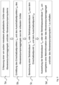
- FIG. 1 shows a wastewater pump system 1 comprising a container 3 for collecting wastewater 4, which enters the container 3 via an inlet line 8.
- a wastewater pump unit 2 is arranged in the container 3 in order to pump the wastewater 4 out of the container 3 via a pressure line 9.
- the pressure line 9 is connected to the pressure side 7 of the wastewater pump unit 2.
- the suction side 6 of the wastewater pump unit 2 opens into the area of the container near the bottom in order to suck the wastewater 4 out from there.
- the wastewater pump unit 2 is therefore designed as a submersible pump here.
- the suction side 6 extends into the container 3 via a suction pipe.
- the wastewater pump unit 2 is powered via a supply line 12, which is connected to a controller 10. Also connected to this control 10 is a level sensor 5, which detects the water level 13 in the container 3 and sends it to the control 10 via a measuring line 11.
- a wastewater pump system 1 is known per se. It works autonomously.
- the control 10 switches the wastewater pump unit 2 on when a switch-on level or maximum level is reached in the container 3 and switches it off again when the wastewater 4 has been pumped down to a switch-off level or minimum level.
- a sensor 14 is now provided to detect an externally measurable physical quantity of the sewage pump unit 2, step Sa in Figure 9 .
- the sensor 14 is in the Figure 1 In the first embodiment shown, the sensor 14 is arranged on the outside of a housing part of the sewage pump unit 2 and is therefore separate from the sewage pump unit 2.
- the sensor 14 can be screwed onto the housing part, clamped on and/or attached to it via a magnetic holder.
- the sensor 14 is connected to an evaluation unit 15 via a signal line 19.
- the evaluation unit 15 is set up to continuously check the detected variable, more precisely the signal from the sensor 14, to determine whether the sewage pump unit 2 has been switched on or off. Depending on the type of sensor 14 or the type of its output signal, this can be done in different ways. If necessary, the evaluation unit 15 can also impress a measuring current into the sensor 14 if required.
- the sensor 14 can be a vibration sensor or a magnetic field sensor.
- the physical quantity of the sewage pump unit 2 is its mechanical vibration, which is generated due to the parts rotating in the sewage pump unit 2. The presence of vibrations is an indicator of the operation of the pump unit.
- the vibration sensor can be an acceleration sensor.
- the physical quantity of the sewage pump unit 2 is the magnetic field of the stator, which extends as a stray field outside the housing part when the sewage pump unit 2 is in operation.
- the magnetic field sensor can be a reed contact or a coil. A reed contact is a switch that closes in a magnetic field and a voltage is induced in the coil. The presence of a stray field, thus a closed reed contact or a voltage induced in the coil, are also each an indicator of the operation of the sewage pump unit.
- the evaluation unit 15 can process the sensor signal if necessary, e.g. amplify and/or filter it. It then checks whether it exceeds or falls below a limit value, has a rising or falling edge or has a sign change. These events indicate that the sewage pump unit has been switched on and off. In the event of a Vibration sensor, the evaluation unit 15 can be set up to check the sensor signal to see whether it contains an alternating component or whether the amplitude of the alternating component exceeds a certain limit value, which in both cases indicates operation of the wastewater pump unit.
- the occurrence of a rising edge and/or a positive change in sign can indicate that the wastewater pump unit is switched on, and if the limit value is undershot, the occurrence of a falling edge and/or a negative change in sign (from plus to minus) can indicate that the wastewater pump unit is switched off.
- the evaluation unit 15 determines the switch-on time t on and the switch-off time t off of the sewage pump unit 2, step Sb in Figure 9 .
- the switch-on time t on can, for example, be the time at which an alternating component occurs in the sensor signal or exceeds a limit value.
- the switch-off time t off can, for example, be the time at which the alternating component in the sensor signal disappears or falls below the limit value.
- the switch-on time t on can, for example, be the time at which the sensor signal or the voltage induced in the coil becomes greater than zero or exceeds a limit value. Accordingly, the switch-off time t off can, for example, be the time at which the sensor signal or the voltage induced in the coil becomes zero or falls below the limit value.
- the switch-on time t on can, for example, be the time at which the sensor signal shows an edge falling from a measuring voltage to OV. Accordingly, the switch-off time t off can, for example, be the time at which the sensor signal shows a rising edge from OV to a measuring voltage.
- the switch-on time t on and the switch-off time t off refer to a common reference time t 0 .
- a real-time clock can be present in the evaluation unit 15 so that the switch-on time t on and the switch-off time t off can be expressed in each case by a time of day.
- a counter can run in the evaluation unit 15, so that the switch-on time t on and the switch-off time t off can each represent a counter reading.
- the evaluation unit 15 calculates an operating time T on , see step Sc in Figure 9 , if the switch-on time t on was before the switch-off time t off , or an operating break duration T off , if the switch-off time t off was before the switch-on time t on .
- the method is sensibly carried out continuously, so that a restart after the sewage pump unit 2 has been switched off or a restart after the sewage pump unit 2 has been switched on is or are recorded, so that both a current operating duration T on and a current operating break duration T off are repeatedly calculated.
- the senor 14 is used exclusively to determine the switch-on time t on and the switch-off time t off of the wastewater pump unit 2. It is not required for the proper operation or function of the wastewater pump unit 2. This is completely unaffected by the sensor 14.
- the operating time T on or the operating break time T off is then evaluated in order to obtain at least additional information about the wastewater pump unit 2 and/or the wastewater pump system 1, see step Sd in Figure 9 .
- the evaluation can be carried out in the evaluation unit 15.
- the evaluation is carried out on a remote server 18 which is connected to the Internet 17 and to which the Evaluation unit 15 sends the current operating time T on and/or the current operating break time T off .
- the latter takes place here via a radio connection 16, for example via a mobile network, which forwards this data to the server 18 via the Internet.
- the server 18 can centrally monitor and manage the wastewater pump system 1, in particular a large number of wastewater pump systems 1. Technical errors and/or the need for maintenance can thus be immediately identified by specialist personnel and appropriate measures can be initiated.
- the senor 14 can also be integrated directly into the evaluation unit 15, so that a housing of the evaluation unit 15 is attached to the motor. If the evaluation unit 15 is then arranged under water, communication would not work, so that the evaluation unit 15 preferably establishes a connection to the Internet 17 or server 18 after the wastewater pump unit 2 has been switched off, i.e. after the container 3 has been pumped empty and the evaluation unit 15 is no longer under water, and makes the stored information available about the switch-on time t on , the switch-off time t o ff, the current operating time T on and/or the current operating break time T off .
- the evaluation by the server 18 can be carried out in different ways.
- the additional information can be the volume of wastewater pumped by the wastewater pump unit 2.
- the current operating time T on is multiplied by a nominal or average pumping power that the wastewater pump unit 2 has during operation.
- a nominal or average pumping power can have been measured by the manufacturer for an identically constructed wastewater pump unit 2 and can therefore be available from the server 18.
- further data on the specific application in which the wastewater pump unit 2 is operated can be provided by the Server 18, such as the geodetic head or the system curve, in order to correctly determine the pumping capacity of the wastewater pump unit 2.
- the pumped wastewater volume at a pumping capacity of 60 m 3 /h (1 m 3 /min) is 10 m 3 . If no new wastewater flows into the tank 3 during the pumping process, the pumped wastewater volume should correspond to the so-called switching volume, which corresponds to the tank volume between the maximum water level h on and the minimum water level h off . If it does not correspond to the switching volume, this indicates a faulty condition of the wastewater pumping system 1, as will be explained below.
- Q out is the volume flow of the sewage pump unit 2
- T on is the operating time
- T off is the operating break time
- A is the cross-section (base area) of a cylindrical container 3
- h on is the switch-on level in container 3 at which the sewage pump unit 2 is switched on
- h off is the switch-off level in container 3 at which the sewage pump unit 2 is switched off.
- the additional information relates to the state of the wastewater pump unit 2 or the wastewater pump system 1, in particular indicating whether a faulty state exists.
- the determined operating time T on is compared with a reference operating time T on,ref and the result of the comparison is used to determine the state of the wastewater pump unit 2 and/or the wastewater pump system 1.
- the reference operating time is either a standard operating time that an identical reference wastewater pump unit requires to pump the switching volume out of the container 3, or an earlier operating time of the wastewater pump unit 2 that was recorded, for example, during the initial operation after the installation of the wastewater pump system.
- the reference operating time T on,ref is stored in a memory in the server 18 or in a database to which the server 18 has access. A comparison of the determined operating time T on with the reference operating time T on,ref is possible in Figure 6 visualized.
- a faulty state A in the form of a blockage of the sewage pump unit 2, a bearing or impeller damage of the sewage pump unit 2 or a blockage of the pressure line 9 connected to it is concluded if the operating time T on is greater than or greater by a limit value t lim than the reference operating time T on,ref .
- the server 18 can generate a service message with an alarm and transmit it to a user who can immediately carry out or arrange for maintenance or repair.
- an operating variable of the wastewater pump unit 2 can also be derived from the operating time T on , such as a theoretically pumped volume, and this can be compared with a reference variable, e.g. the switching volume. If the operating variable exceeds the reference variable or exceeds it by a limit value, the faulty state mentioned is also assumed.
- the limit value t lim can, for example, be between 5% and 20% of the reference operating time T on,ref or the reference value in order to take measurement inaccuracies into account.
- a faulty state B in the form of a deposit such as a sediment accumulation in the container 3 can be concluded if the operating time T on or the value derived therefrom is less than or less than the reference operating time T on,ref or the reference value by a limit value t lim .
- the comparison between operating time T on and reference operating time T on,ref is illustrated by Figure 7 .
- the operating time T on or the operating break time T off are calculated for each operation of the waste water pump unit 2 and a trend is determined from the calculated operating times T on or operating break times T off .
- Figure 8 illustrates the case where the operating time T on is longer than before each time the sewage pump unit 2 is operated, so that a trend ⁇ T on / ⁇ t greater than zero is present. The trend can be compared with a limit value in order to determine whether the gradual increase in the operating time T on is due to expected wear or is caused by a faulty condition.
- a faulty condition in the form of a blockage in the sewage pump unit 2, a bearing or impeller defect in the sewage pump unit 2 or a blockage in the pressure line 9 connected to it is concluded if the trend ⁇ T on / ⁇ t of the operating times T on is positive and exceeds a limit value in terms of amount.
- a faulty condition in the form of a deposit, in particular an accumulation of sediment in the container 3 is concluded if the trend of the operating time T on is negative and falls below a limit value in terms of amount.
- Figures 2 and 3 show to Figure 1 alternative design variants. They differ from the variant in Figure 1 only in the local arrangement of the sensor 14.
- the sensor in the design variant according to Figure 2 on the pressure line 9. Since this is mechanically connected to the sewage pump unit 2, its vibrations are also transmitted to the pressure line 9.
- the sensor 14 is therefore also a vibration sensor.
- the advantage of this variant is that the sensor is positioned dry and can therefore be easily retrofitted.
- the sensor 14 is an inductive current sensor with a toroidal core through which the supply cable 12 of the sewage pump unit 2 is routed. The physical quantity detected by the sewage pump unit 2 is therefore its current consumption. When the sewage pump unit 2 is switched on, the signal from the sensor 14 indicates a current flow.
- the sensor signal After the sewage pump unit 2 is switched off, the sensor signal is zero. Thus, a rising edge in the sensor signal or an exceedance of a signal limit value indicates the switch-on time t on and a falling edge in the sensor signal or an undershoot of a signal limit value indicates the switch-off time t off .
- the evaluation unit 15 checks the sensor signal for the occurrence of one of the above-mentioned events (edge, exceedance/undershoot of limit value) in order to determine the switch-on time t on and the switch-off time t off . From this, it then calculates the operating time T on and/or the operating break time T off as before and forwards these to the server 18, which then carries out an evaluation as described above.
- the wastewater pump system 1 comprises a first wastewater pump unit 2a and at least one second wastewater pump unit 2b.
- the method according to the invention is also carried out on the second wastewater pump unit 2b, ie its operating time T on and/or operating break time T off is calculated and at least one additional piece of information about the second wastewater pump unit 2b and/or the wastewater pump system 1 is determined therefrom, as explained above with reference to the first wastewater pump unit 2a or the case of a single wastewater pump unit 2.
- Both wastewater pump units 2a, 2b each have a sensor 14 which is connected via a corresponding signal line 19 to an evaluation unit 15, 15a, 15b which, as described above, evaluates the respective sensor signal.
- the respective operating time T on is not compared with a standard operating time T on,ref or a previous operating time of the respective wastewater pump unit 2a, 2b, but rather the Operating time T on of the first wastewater pump unit 2a is compared with the operating time T on of the second wastewater pump unit 2b.
- the reference operating time T on,ref here is the calculated operating time T on of the second wastewater pump unit 2b.
- FIG. 4 illustrates a wastewater pump system 1 in which the second wastewater pump unit 2b is arranged together with the first wastewater pump unit 2a in the container 3 and is operated alternately with it. Both wastewater pump units 2a are switched on and off by the same control 10. A faulty state in the form of a blockage of the first wastewater pump unit 2a, a bearing or impeller damage of the first wastewater pump unit 2a or a blockage of the sewage line 9 connected to it is concluded if the operating time T on of the first wastewater pump unit 2a is greater than or greater by a limit value than the operating time T on of the second wastewater pump unit 2b.
- FIG. 5 illustrates a wastewater pump system 1 in which the first wastewater pump unit 2a is arranged in a first container 3a and the second wastewater pump unit 2b is arranged in a second container 3b.
- Each wastewater pump unit 2a, 2b is switched on and off by its own control 10, depending on the water level 13 in the respective container 3a, 3b, which is transmitted by a level sensor 5 via a measuring line 11a, 11b to the respective control 10.
- the second container 3b is connected to the first container 3a via a wastewater line 9a, 8b.
- the wastewater line 9a, 8b consists of a pressure line 9a, which is connected to the first wastewater pump unit 2a and transports the waste water pumped by it, and an adjoining inlet line 8b, via which the waste water 4 is fed into the second container 3b.
- the first and second containers 3a, 3b are separated from each other by a longer distance, for example several hundred meters, in order to transport the waste water 4 to a water treatment plant.
- a longer distance for example several hundred meters
- waste water pump units 2a, 2b are required for this purpose.
- Each wastewater pump unit 2a, 2b is also assigned a corresponding sensor 14, which is a vibration sensor here, for example.
- Each of the sensors 14 transmits its sensor signal via a signal line 19 to a corresponding evaluation unit 15a, 15b, which, as previously described, evaluates the respective sensor signal for the occurrence of an event indicating the switch-on time t on and the switch-off time t off and then calculates the operating time T on and/or the operating break time T off of the respective wastewater pump unit 2a, 2b.
- Each evaluation unit 15a, 15b then transmits this to the server 18 for further evaluation or to obtain additional information about the wastewater pump system 1.
- the wastewater pump system 1 is in a faulty state in the form of a leak in the wastewater line 9a, 8b if the sum of the operating times T on of the first wastewater pump unit 2a in a certain observation period is greater than or greater by a limit value than the sum of the operating times T on of the second wastewater pump unit 2a in the observation period, which in this case forms the reference operating time T on,ref .
- a faulty condition of the sewage pump system 1 in the form of an impermissible inflow of water into the Wastewater line 9a, 8b is closed if the sum of the operating times T on of the first wastewater pump unit 2a in a specific observation period is less than or less than a limit value than the sum of the reference operating times T on,ref in the observation period. In this case, water enters the wastewater pump system 1 which is not intended to be pumped by it.
- the operating break time T off of the second wastewater pump unit 2b i.e. the period between two operations of the second wastewater pump unit 2b, is repeatedly determined and compared with a reference break time T off,ref .
- a faulty state in the form of an abnormal inflow of water into the wastewater pump system 2 is concluded if the operating break time T off is repeatedly less than or less than the reference break time T off,ref by a limit value.
- the reference break time T off,ref can in this case be the average operating break time T off of the second wastewater pump unit 2b.
- the method according to the invention can be used in a variety of different wastewater pumping systems.
- the invention includes any changes, variations or modifications of embodiments which involve the exchange, addition, change or omission of elements, components, process steps, values or information, as long as the basic idea of the invention is retained, regardless of whether the change, variation or modification results in an improvement or deterioration of an embodiment.
Landscapes
- Engineering & Computer Science (AREA)
- Mechanical Engineering (AREA)
- General Engineering & Computer Science (AREA)
- Health & Medical Sciences (AREA)
- Life Sciences & Earth Sciences (AREA)
- Hydrology & Water Resources (AREA)
- Public Health (AREA)
- Water Supply & Treatment (AREA)
- Control Of Positive-Displacement Pumps (AREA)
- Control Of Non-Positive-Displacement Pumps (AREA)
Abstract
Die Erfindung betrifft ein Verfahren zur Informationsgewinnung, insbesondere zur Zustandsüberwachung, bei einem Abwasserpumpenaggregat (2) eines Abwasserpumpensystems (1) und/oder bei einem zumindest ein Abwasserpumpenaggregat (2, 2a) umfassendes Abwasserpumpensystem (1), wobei das Abwasserpumpenaggregat (2, 2a) im Betrieb Abwasser (4) aus einem Behältnis (3) zum Sammeln des Abwassers (4) abpumpt. Dabei wird mit Hilfe eines separaten Sensors (14), eine von außen messbare physikalische Größe des Abwasserpumpenaggregats (2, 2a) und/oder -systems (1) erfasst, aus der erfassten Größe der Einschaltzeitpunkt (t<sub>on</sub>) und der Ausschaltzeitpunkt (t<sub>off</sub>) des Abwasserpumpenaggregats (2, 2a) ermittelt, daraus eine Betriebsdauer (T<sub>on</sub>) oder Betriebspausendauer (T<sub>off</sub>) berechnet, die dann ausgewertet wird, um wenigstens eine Mehrinformation über das Abwasserpumpenaggregat (2, 2a) und/oder das Abwasserpumpensystem (1) zu erhalten.The invention relates to a method for obtaining information, in particular for condition monitoring, in a wastewater pump unit (2) of a wastewater pump system (1) and/or in a wastewater pump system (1) comprising at least one wastewater pump unit (2, 2a), wherein the wastewater pump unit (2, 2a) pumps wastewater (4) out of a container (3) for collecting the wastewater (4) during operation. In this case, with the aid of a separate sensor (14), an externally measurable physical quantity of the wastewater pump unit (2, 2a) and/or system (1) is recorded, the switch-on time (t<sub>on</sub>) and the switch-off time (t<sub>off</sub>) of the wastewater pump unit (2, 2a) are determined from the recorded quantity, and an operating time (T<sub>on</sub>) or operating break time (T<sub>off</sub>) is calculated therefrom, which is then evaluated in order to obtain at least additional information about the wastewater pump unit (2, 2a) and/or the wastewater pump system (1).
Description
Die Erfindung betrifft ein Verfahren zur Informationsgewinnung, insbesondere zur Zustandsüberwachung, bei einem Abwasserpumpenaggregat eines Abwasserpumpensystems und/oder bei einem zumindest ein Abwasserpumpenaggregat umfassenden Abwasserpumpensystem, wobei das Abwasserpumpenaggregat im Betrieb Abwasser aus einem Behältnis zum Sammeln des Abwassers abpumpt.The invention relates to a method for obtaining information, in particular for condition monitoring, in a wastewater pump unit of a wastewater pump system and/or in a wastewater pump system comprising at least one wastewater pump unit, wherein the wastewater pump unit, during operation, pumps wastewater out of a container for collecting the wastewater.
Abwasserpumpensysteme sammeln Abwasser, beispielsweise Regenwasser, Oberflächenwasser, Prozesswasser, Grauwasser und/ oder Schwarzwasser in einem Behältnis. Das Abwasser wird von wenigstens einem entsprechenden Abwasserpumpenaggregat abgepumpt, sobald es in dem Behältnis einen bestimmten Maximalpegelstand erreicht, der durch einen Pegelstandssensor im oder am Behältnis, beispielsweise einem Schwimmer, gemessen wird. Derartige Abwasserpumpensysteme werden auch als Hebeanlagen bezeichnet. Ist der Maximalpegelstand erreicht, wird das Abwasserpumpenaggregat eingeschaltet. Es wird wieder ausgeschaltet, wenn ein bestimmter Minimalpegelstand erreicht ist. Abwasserpumpenaggregate werden somit nur bedarfsweise und mit vergleichsweise kurzen Betriebsdauern betrieben, beispielsweise eine halbe bis wenige Minuten. Die Betriebsdauern sind für ein bestimmtes Abwasserpumpensystem nach der Inbetriebnahme stets gleich lang, da das durch den Maximal- und den Minimalpegelstand definierte Abwasservolumen, das abgepumpt werden muss, konstant ist. Das Abwasserpumpenaggregat wird dabei üblicherweise ungeregelt, d.h. mit einer konstanten Drehzahl betrieben.Wastewater pump systems collect wastewater, for example rainwater, surface water, process water, grey water and/or black water, in a container. The wastewater is pumped out by at least one corresponding wastewater pump unit as soon as it reaches a certain maximum level in the container, which is measured by a level sensor in or on the container, for example a float. Such wastewater pump systems are also known as lifting systems. Once the maximum level is reached, the wastewater pump unit is switched on. It is switched off again when a certain minimum level is reached. Wastewater pump units are therefore only operated when required and for comparatively short operating times, for example half a minute to a few minutes. The operating times for a specific wastewater pump system are always the same after commissioning, since the volume of wastewater that has to be pumped out, defined by the maximum and minimum levels, is constant. The wastewater pump unit is usually operated unregulated, i.e. at a constant speed.
Der mit der Zeit zunehmende Verschleiß des Abwasserpumpenaggregats, insbesondere der Lager und/ oder des Laufrads, Ablagerungen am Laufrad oder Pumpengehäuse und/ oder eine Verstopfung der Ansaug- oder Auslassöffnung des Abwasserpumpenaggregats bewirken eine allmähliche oder spontan stark zunehmende Betriebsdauer. Gleichzeitig führen Ablagerungen in dem Behältnis zu einer Abnahme der Betriebsdauer, da das effektiv pumpbare Volumen kleiner wird. Die Betriebsdauer ist somit ein Indikator für den Zustand eines Abwasserpumpensystems, respektive dessen Abwasserpumpenaggregats.The increasing wear of the sewage pump unit over time, particularly the bearings and/or the impeller, deposits on the impeller or pump housing and/or a blockage of the suction or discharge opening of the sewage pump unit result in a gradual or spontaneously sharp increase in the operating time. At the same time, deposits in the container lead to a reduction in the operating time, as the effectively pumpable volume becomes smaller. The operating time is therefore an indicator of the condition of a sewage pump system, or rather its sewage pump unit.
Für eine Zustandsüberwachung von Pumpenaggregaten ist es allgemein bekannt, eine vergleichsweise komplexe Mess- und Auswertetechnik mit einem oder mehreren Sensoren zu verwenden. So wird zur Erkennung einer Verstopfung eines Abwasserpumpenaggregats beispielsweise dessen Betriebspunkt kontinuierlich auf eine gewisse Änderung hin überwacht. Hierzu werden Sensoren z.B. zur Erfassung hydraulischer Größen wie der von der Pumpe erzeugte Differenzdruck und/ oder der gepumpte Volumenstrom, oder Sensoren zur Erfassung elektrischer Größen wie der Stromaufnahme, der Eingangs- und/ oder Ausgangsspannung und/ oder der Leistungsaufnahme verwendet. Alternativ kann eine Verstopfung anhand von Vibrationen des Abwasserpumpenaggregats erkannt werden, die mittels Beschleunigungssensoren erfasst werden. Zum Teil werden meist mehrere Sensoren benötigt, um eine bestimmte Information, insbesondere über einen bestimmten Zustand, zu erhalten.It is generally known that a relatively complex measurement and evaluation technology with one or more sensors is used to monitor the condition of pump units. For example, to detect a blockage in a wastewater pump unit, its operating point is continuously monitored for a certain change. For this purpose, sensors are used, for example, to record hydraulic variables such as the differential pressure generated by the pump and/or the pumped volume flow, or sensors to record electrical variables such as the current consumption, the input and/or output voltage and/or the power consumption. Alternatively, a blockage can be detected based on vibrations in the wastewater pump unit, which are recorded using acceleration sensors. In some cases, several sensors are usually required to obtain specific information, especially about a specific condition.
Die Messsignale solcher Sensoren werden im Falle analoger Signale regelmäßig verstärkt, ggf. gefiltert und digitalisiert, anschließend ausgewertet. Auch bei digitalen Signalen erfolgt meist eine Filterung, um das Signal-Rausch-Verhältnis zu verbessern, sowie eine anschließende Auswertung, beispielsweise durch Vergleich mit einem Grenzwert oder durch eine Frequenzanalyse.In the case of analog signals, the measurement signals from such sensors are regularly amplified, filtered and digitized if necessary, and then evaluated. Digital signals are also usually filtered to improve the signal-to-noise ratio, and then evaluated, for example by comparing them with a limit value or by performing a frequency analysis.
Es versteht sich von selbst, dass für die genannten Zwecke sowohl die notwendigen Sensoren, als auch die notwendige Elektronik für die Verarbeitung und Auswertung der Sensorsignale zur Gewinnung einer gewünschten Information vergleichsweise komplex, teuer und aufwändig in das Abwasserpumpenaggregat oder Abwasserpumpensystem zu installieren oder zu integrieren sind. Fehlt die Funktionalität der Gewinnung der gewünschten Information bei dem Abwasserpumpenaggregat oder dem Abwasserpumpensystem ist eine Nachrüstung entweder gar nicht oder nur mit erheblichem Aufwand und Kosten möglich.It goes without saying that for the purposes mentioned, both the necessary sensors and the necessary electronics for processing and evaluating the sensor signals to obtain the desired information are comparatively complex, expensive and time-consuming to install or integrate into the sewage pump unit or sewage pump system. If the Due to the lack of functionality for obtaining the desired information from the sewage pump unit or the sewage pump system, retrofitting is either not possible at all or only possible with considerable effort and expense.
Es ist Aufgabe der vorliegenden Erfindung, eine technisch sehr einfache, kostengünstige und nachrüstbare Möglichkeit der Gewinnung wenigstens einer gewünschten Mehrinformation bei einem Abwasserpumpenaggregat oder einem Abwasserpumpensystem mit wenigstens einem Abwasserpumpenaggregat bereitzustellen.It is an object of the present invention to provide a technically very simple, cost-effective and retrofittable possibility of obtaining at least one desired additional information in a wastewater pump unit or a wastewater pump system with at least one wastewater pump unit.
Diese Aufgabe wird durch ein Verfahren mit den Merkmalen des Anspruchs 1 gelöst. Vorteilhafte Weiterbildungen sind in den Unteransprüchen angegeben und werden nachfolgend erläutert.This object is achieved by a method having the features of
Erfindungsgemäß wird vorgeschlagen, das gattungsgemäße Verfahren dahingehend weiterzubilden, dass
- a) mit Hilfe eines separaten Sensors, eine von außen messbare physikalische Größe des Abwasserpumpenaggregats und/oder des Abwasserpumpensystems erfasst wird,
- b) aus der erfassten Größe der Einschaltzeitpunkt und der Ausschaltzeitpunkt des Abwasserpumpenaggregats ermittelt wird,
- c) aus dem Einschaltzeitpunkt und dem Ausschaltzeitpunkt eine Betriebsdauer oder Betriebspausendauer berechnet wird, wobei der Sensor dazu verwendet wird, den Einschaltzeitpunkt und den Ausschaltzeitpunkt des Abwasserpumpenaggregats zu ermitteln, und
- d) die Betriebsdauer oder die Betriebspausendauer ausgewertet wird, um wenigstens eine Mehrinformation über das Abwasserpumpenaggregat und/oder das Abwasserpumpensystem zu erhalten.
- a) by means of a separate sensor, an externally measurable physical quantity of the sewage pump unit and/or the sewage pump system is recorded,
- b) the switch-on time and switch-off time of the sewage pump unit are determined from the measured value,
- c) an operating time or operating break time is calculated from the switch-on time and the switch-off time, whereby the sensor is used to determine the switch-on time and the switch-off time of the sewage pump unit, and
- d) the operating time or the operating break time is evaluated in order to obtain at least additional information about the waste water pump unit and/or the waste water pump system.
Als Einschaltzeitpunkt des Abwasserpumpenaggregats ist, in Abhängigkeit der Art des verwendeten Sensors bzw. der Art der gemessenen physikalischen Größe, jener Zeitpunkt zu verstehen, ab dem es zu pumpen beginnt oder ab dem der Antriebsmotor des Abwasserpumpenaggregats bestromt wird, oder ab dem ein elektromagnetisches Feld im Antriebsmotor besteht oder dreht, oder ab dem der Rotor respektive das Pumpenlaufrad zu drehen beginnt, oder Vibrationen auftreten. In entsprechender Weise ist als Ausschaltzeitpunkt des Abwasserpumpenaggregats jener Zeitpunkt zu verstehen, ab dem es zu pumpen aufhört oder ab dem der Antriebsmotor des Abwasserpumpenaggregats nicht mehr bestromt wird, oder ab dem ein elektromagnetisches Feld im Elektromotor nicht mehr dreht, oder ab dem der Rotor respektive das Pumpenlaufrad aufgehört hat zu drehen, oder Vibrationen enden.The switch-on time of the sewage pump unit is, depending on the type of sensor used or the type of physical quantity measured, the time at which it starts to pump or at which the drive motor of the sewage pump unit is energized, or at which an electromagnetic field exists or rotates in the drive motor, or at which the Rotor or the pump impeller begins to rotate or vibrations occur. Similarly, the switch-off point of the sewage pump unit is the point in time at which it stops pumping or at which the drive motor of the sewage pump unit is no longer energized or at which an electromagnetic field in the electric motor no longer rotates or at which the rotor or the pump impeller has stopped rotating or vibrations stop.
Je nach verwendetem Sensor können sich die genannten Zeitpunkte wenige Millisekunden bis Sekunden unterscheiden. So gibt die Bestromung des Elektromotors den frühesten Zeitpunkt an, der als Einschaltzeitpunkt betrachtet werden kann. Die Bestromung führt augenblicklich zu einem elektromagnetischen Feld im Antriebsmotor, so dass der Aufbau oder die plötzliche Existenz eines solchen elektromagnetischen Feldes ebenfalls als Einschaltzeitpunkt betrachtet werden kann. Der Rotor beginnt, nach Überwindung der Massenträgheit, wenige hundert Millisekunden später infolge des an ihm durch das Feld wirkenden Drehmoments zu drehen, so dass alternativ auch der Drehbeginn als Einschaltzeitpunkt betrachtet werden kann. Der Rotor läuft dann allmählich hoch, bis die Betriebsdrehzahl erreicht ist. Dies kann einige Sekunden dauern. Infolge der Drehung des Rotors und des Laufrades erzeugt das Abwasserpumpenaggregats Vibrationen, die an seinem Gehäuse (Pumpen- und/ oder Motorgehäuse) erfasst werden können und ab einer bestimmten Drehzahl merklich sind. Als Einschaltzeitpunkt kann somit auch der Zeitpunkt betrachtet werden, ab dem Vibrationen messbar auftreten oder einen Grenzwert überschreiten. Ab einer anderen bestimmten Drehzahl, fördert das Abwasserpumpenaggregat, so dass gemäß einer weiteren Alternative als Einschaltzeitpunkt, derjenige Zeitpunkt betrachtet werden kann, ab dem der Volumenstrom größer null oder größer einem Grenzwert ist.Depending on the sensor used, the times mentioned can differ by a few milliseconds to seconds. For example, the energization of the electric motor indicates the earliest time that can be considered the switch-on time. The energization immediately leads to an electromagnetic field in the drive motor, so that the build-up or sudden existence of such an electromagnetic field can also be considered the switch-on time. After overcoming the inertia of the mass, the rotor begins to rotate a few hundred milliseconds later as a result of the torque acting on it through the field, so that alternatively the start of rotation can also be considered the switch-on time. The rotor then gradually increases until the operating speed is reached. This can take a few seconds. As a result of the rotation of the rotor and the impeller, the sewage pump unit generates vibrations that can be detected on its housing (pump and/or motor housing) and are noticeable from a certain speed. The switch-on time can therefore also be considered to be the time at which vibrations become measurable or exceed a limit value. From another specific speed, the sewage pump unit pumps, so that according to a further alternative, the switch-on time can be considered to be the time at which the volume flow is greater than zero or greater than a limit value.
Entsprechend dieser Einschaltzeitpunkte können sich auch die Ausschaltzeitpunkte um wenige Millisekunden bis Sekunden unterscheiden. So stellt das Abschalten der Bestromung des Antriebsmotors den frühesten Zeitpunkt dar, der als Abschaltzeitpunkt betrachtet werden kann. Das Abschalten der Bestromung führt augenblicklich zum Abbau des elektromagnetischen Felds im Antriebsmotor, was als Ausschaltzeitpunkt betrachtet werden kann. Allerdings besteht im Falle eines permanentmagnetischen Rotors, und infolge der Remanenz auch im Falle eines Induktionsmotors, weiterhin ein magnetisches Feld, das aufgrund der fortgesetzten Drehung des Rotors ebenfalls weiter rotiert, so dass alternativ als Ausschaltzeitpunkt jener Zeitpunkt betrachtet werden kann, ab dem das Feld nicht mehr dreht. Dies ist erst beim Stillstand des Rotors der Fall, auf den dieser aufgrund der mechanischen und hydraulischen Reibung abgebremst wird, was mehrere Sekunden dauern kann. Durch die stetig abnehmende Drehzahl werden außerdem die Vibrationen und der Volumenstrom geringer. Als Ausschaltzeitpunkt kann somit gemäß einer weiteren Alternative auch der Zeitpunkt betrachtet werden, ab dem Vibrationen nicht mehr messbar sind oder unterhalb einem Grenzwert liegen, oder ab dem der Volumenstrom nicht mehr messbar ist oder unter einem bestimmten Grenzwert liegt, also das Abwasserpumpenaggregat nicht mehr fördert.According to these switch-on times, the switch-off times can also differ by a few milliseconds to seconds. For example, switching off the power supply to the drive motor represents the earliest time that can be considered as the switch-off time. Switching off the power supply immediately leads to the reduction of the electromagnetic field in the drive motor, which can be considered as the switch-off time. However, in the case of a permanent magnet rotor, and as a result of the remanence also in the case of an induction motor, a magnetic field continues to rotate due to the continued rotation of the rotor, so that alternatively the switch-off time can be considered to be the time at which the field no longer rotates. This only happens when the rotor comes to a standstill, to which it is braked due to mechanical and hydraulic friction, which can take several seconds. The constantly decreasing speed also reduces the vibrations and the volume flow. According to a further alternative, the switch-off time can therefore also be considered to be the time at which vibrations are no longer measurable or are below a limit value, or at which the volume flow is no longer measurable or is below a certain limit value, i.e. the sewage pump unit no longer pumps.
Obgleich die genannten Einschaltzeitpunkte und die genannten Ausschaltzeitpunkte jeweils bezogen auf einen absoluten Referenzzeitpunkt verschieden sein können, kommt es im Rahmen der Erfindung auf den genauen Einschaltzeitpunkt und den genauen Ausschaltzeitpunkt nicht an, da sie zur Bestimmung der Betriebsdauer oder Betriebspausendauer zueinander in Bezug gesetzt werden. Wichtig ist allein, dass sich die Art der Messung des Einschaltzeitpunkts und des Ausschaltzeitpunkts auf nicht ändert.Although the switch-on times and switch-off times mentioned can each be different in relation to an absolute reference time, the exact switch-on time and the exact switch-off time are not important within the scope of the invention, since they are related to each other to determine the operating time or operating break time. The only important thing is that the type of measurement of the switch-on time and the switch-off time does not change.
Die Betriebsdauer ist die Differenz zwischen dem Ausschaltzeitpunkt und dem vorherigen Einschaltzeitpunkt. Entsprechend ist die Betriebspausendauer ist die Differenz zwischen dem Einschaltzeitpunkt und dem vorherigen Ausschaltzeitpunkt.The operating time is the difference between the switch-off time and the previous switch-on time. Accordingly, the operating break time is the difference between the switch-on time and the previous switch-off time.
Als Abwasserpumpenaggregat ist ein solches Pumpenaggregat zu verstehen, dass bestimmungsgemäß zum Abpumpen von Abwasser wie Regenwasser, Oberflächenwasser, Prozesswasser, Grauwasser und/ oder Schwarzwasser aus einem Behältnis vorgesehen ist, der zum Sammeln des Abwassers dient. Das Abwasser kann mit Stückgut behaftet sein.A wastewater pump unit is a pump unit that is designed to pump wastewater such as rainwater, surface water, process water, grey water and/or black water from a container that is used to collect the wastewater. The wastewater may contain bulk goods.
Ein Pumpenaggregat umfasst eine Pumpeneinheit, einen Elektromotor, der der diese Pumpeneinheit direkt oder über eine Kupplung und/ oder ein Getriebe antreibt, und eine Antriebselektronik, die den Elektromotor bestromt, insbesondere steuert und/ oder regelt. Die Pumpeneinheit, der Elektromotor und die Antriebselektronik können baulich eine Einheit bilden oder räumlich getrennt voneinander aufgestellt sein.A pump unit comprises a pump unit, an electric motor which drives this pump unit directly or via a clutch and/or a gear, and drive electronics which energise the electric motor, in particular controls and/or or regulates. The pump unit, the electric motor and the drive electronics can form a structural unit or be installed spatially separate from one another.
Die Pumpeneinheit ist bevorzugt in der Art einer Kreiselpumpe ausgebildet. Der Elektromotor kann ein Drehstrommotor, vorzugsweise ein elektronisch kommutierter Synchronmotor sein. Geeigneterweise sind die Motorwelle und die Pumpenwelle einteilig, so dass das dem Elektromotor gegenüberliegende freie Ende der Motorwelle das Pumpenlaufrad trägt. Die Antriebselektronik kann einen Frequenzumrichter umfassen.The pump unit is preferably designed in the form of a centrifugal pump. The electric motor can be a three-phase motor, preferably an electronically commutated synchronous motor. The motor shaft and the pump shaft are suitably one-piece, so that the free end of the motor shaft opposite the electric motor carries the pump impeller. The drive electronics can comprise a frequency converter.
Es kann vorgesehen sein, dass in Schritt d) die Betriebsdauer, oder eine daraus bestimmte Betriebsgröße, mit einer Referenzbetriebsdauer oder einer Referenzgröße verglichen wird, wobei aus dem Ergebnis des Vergleichs auf den Zustand, insbesondere einen Fehlerzustand des Abwasserpumpenaggregats und/oder des Abwasserpumpensystems geschlossen wird. Somit ist die Mehrinformation eine Information über den Zustand des Abwasserpumpenaggregats und/oder des Abwasserpumpensystems. Die berechnete Betriebsdauer ist die aktuelle Betriebsdauer des Abwasserpumpenaggregats.It can be provided that in step d) the operating time, or an operating variable determined therefrom, is compared with a reference operating time or a reference variable, with the result of the comparison being used to determine the state, in particular a fault state, of the wastewater pump unit and/or the wastewater pump system. The additional information is therefore information about the state of the wastewater pump unit and/or the wastewater pump system. The calculated operating time is the current operating time of the wastewater pump unit.
Gemäß einer Ausführungsvariante kann die Referenzbetriebsdauer eine frühere Betriebsdauer des Abwasserpumpenaggregats sein. Diese frühere Betriebsdauer kann beispielsweise bei der ersten Inbetriebnahme des Abwasserpumpenaggregats bzw. des Abwasserpumpensystems ermittelt werden. Alternativ kann als Referenzbetriebsdauer eine Standardbetriebsdauer verwendet werden. Die Standardbetriebsdauer kann jene Betriebsdauer sein, die im fehlerfreien Normalbetrieb eines baugleichen anderen Abwasserpumpenaggregats bei einer bestimmten Betriebsdrehzahl, beispielsweise Nenndrehzahl, benötigt wird, um das Behältnis von einem Maximalpegelstand bis zu einem Minimalpegelstand zu leeren. Diese Standardbetriebsdauer kann werksseitig beim Hersteller ermittelt worden sein und stellvertretend für alle zum Abwasserpumpenaggregat baugleichen Pumpenaggregate gelten.According to one design variant, the reference operating time can be an earlier operating time of the wastewater pump unit. This earlier operating time can be determined, for example, when the wastewater pump unit or the wastewater pump system is first put into operation. Alternatively, a standard operating time can be used as the reference operating time. The standard operating time can be the operating time that is required in fault-free normal operation of another wastewater pump unit of the same design at a certain operating speed, for example nominal speed, to empty the container from a maximum water level to a minimum water level. This standard operating time can have been determined at the manufacturer's factory and can be representative of all pump units of the same design as the wastewater pump unit.
Durch den Vergleich der tatsächlich benötigten Betriebsdauer mit der Referenzbetriebsdauer kann festgestellt werden, ob und inwieweit sich der Betriebszustand des Abwasserpumpenaggregats und/ oder Abwasserpumpensystems verschlechtert bzw. verschlechtert hat. Beispielsweise kann auf einen fehlerhaften Zustand in Gestalt einer Verstopfung, eines Lager- oder Laufradschaden des Abwasserpumpenaggregats oder auf eine Verstopfung einer daran angeschlossenen Druckleitung geschlossen werden, wenn die berechnete Betriebsdauer größer als oder um einen Grenzwert größer als die Referenzbetriebsdauer ist. Alternativ oder kumulativ kann auf einen fehlerhaften Zustand in Gestalt einer Ablagerung, insbesondere einer Sedimentansammlung in dem Behältnis geschlossen werden, wenn die berechnete Betriebsdauer kleiner als oder um einen Grenzwert kleiner als die Referenzbetriebsdauer ist.By comparing the actual operating time required with the reference operating time, it can be determined whether and to what extent the The operating condition of the sewage pump unit and/or sewage pump system has deteriorated or has deteriorated. For example, a faulty condition in the form of a blockage, bearing or impeller damage to the sewage pump unit or a blockage in a pressure line connected to it can be concluded if the calculated operating time is greater than or greater than the reference operating time by a limit value. Alternatively or cumulatively, a faulty condition in the form of a deposit, in particular an accumulation of sediment in the container, can be concluded if the calculated operating time is less than or less than the reference operating time by a limit value.
Alternativ zu dem Vergleich der berechneten Betriebsdauer mit der Referenzbetriebsdauer, kann aus der Betriebsdauer zunächst eine Betriebsgröße berechnet und dann diese mit dem Wert einer Referenzgröße verglichen werden, um die Mehrinformation zu erhalten.As an alternative to comparing the calculated operating time with the reference operating time, an operating variable can first be calculated from the operating time and then compared with the value of a reference variable in order to obtain additional information.
Beispielsweise kann die Betriebsgröße ein theoretisches, vom Pumpenaggregat gepumptes Abwasservolumen sein, welches man durch Multiplikation der ermittelten Betriebsdauer mit einer erwarteten Pumpleistung in Volumen pro Zeiteinheit erhält, z.B. in l/min oder m3/min. Die erwartete Pumpleistung kann jene nominale Leistung sein, die ein zum Abwasserpumpenaggregat baugleiches Abwasserpumpenaggregat im fehlerfreien Normalbetrieb bei einer bestimmten Betriebsdrehzahl, beispielsweise Nenndrehzahl, besitzt und die werksseitig beim Hersteller ermittelt werden kann. Die Referenzgröße ist dann ebenfalls ein Volumen, insbesondere jenes Behälterteilvolumen, das sich durch die Multiplikation der Differenz aus Maximalpegelstand und Minimalpegelstand mit der Grundfläche des Behältnisses ergibt. In dieser Ausführungsvariante werden somit anstelle von Betriebsdauern zwei Volumina miteinander verglichen.For example, the operating variable can be a theoretical volume of wastewater pumped by the pump unit, which is obtained by multiplying the determined operating time by an expected pumping capacity in volume per unit of time, e.g. in l/min or m 3 /min. The expected pumping capacity can be the nominal capacity that a wastewater pump unit of the same design as the wastewater pump unit has in fault-free normal operation at a certain operating speed, e.g. nominal speed, and which can be determined by the manufacturer at the factory. The reference variable is then also a volume, in particular the partial volume of the container that results from multiplying the difference between the maximum water level and the minimum water level by the base area of the container. In this design variant, two volumes are compared with each other instead of operating times.
Verlängert sich die Betriebsdauer, so würde sich auch der Wert der berechneten Betriebsgröße, im vorliegenden Fall das gepumpte Volumen erhöhen. Da das gepumpte Volumen aber nicht größer sein kann, als das von der Referenzgröße angegebene Behälterteilvolumen, ergibt sich aus dem Vergleich der berechneten Betriebsgröße mit der Referenzgröße als Mehrinformationen, dass sich der Zustand des Pumpenaggregats verschlechtert bzw. verschlechtert hat, wenn die berechnete Betriebsgröße größer als die Referenzgröße ist oder wird. Beispielsweise kann auf einen fehlerhaften Zustand in Gestalt einer Verstopfung, eines Lager- oder Laufradschaden des Abwasserpumpenaggregats oder auf eine Verstopfung einer daran angeschlossenen Druckleitung geschlossen werden, wenn die berechnete Betriebsgröße größer als oder um einen Grenzwert größer als die Referenzgröße ist. Alternativ oder kumulativ kann auf einen fehlerhaften Zustand in Gestalt einer Ablagerung, insbesondere einer Sedimentansammlung in dem Behältnis geschlossen werden, wenn die berechnete Betriebsgröße kleiner als oder um einen Grenzwert kleiner als die Referenzgröße ist.If the operating time is extended, the value of the calculated operating variable, in this case the pumped volume, would also increase. However, since the pumped volume cannot be larger than the partial tank volume specified by the reference variable, the comparison of the calculated operating variable with the reference variable provides additional information that the condition of the pump unit has deteriorated or has deteriorated if the calculated operating variable is or becomes greater than the reference variable. For example, a faulty condition in the form of a blockage, bearing or impeller damage to the wastewater pump unit or a blockage in a pressure line connected to it can be concluded if the calculated operating variable is greater than or greater than the reference variable by a limit value. Alternatively or cumulatively, a faulty condition in the form of a deposit, in particular an accumulation of sediment in the container, can be concluded if the calculated operating variable is less than or less than the reference variable by a limit value.
In einer Ausführungsvariante wird die Betriebsdauer oder Betriebspausendauer gemäß der Schritte a) bis c) bei jedem Betrieb des Abwasserpumpenaggregats wiederholt berechnet. Aus den berechneten Betriebsdauern oder Betriebspausendauern wird dann ein Trend ermittelt, der die Betriebsgröße bildet. Die Betriebsgröße gibt in dieser Ausführungsvariante somit an, ob, in welche Richtung und wie stark sich die Betriebsdauer oder Betriebspausendauer mit der Zeit ändert. Die Referenzgröße kann einen Grenzwert für den Trend bilden. Auf einen fehlerhaften Zustand in Gestalt einer Verstopfung des Abwasserpumpenaggregats, eines Lager- oder Laufradschaden des Abwasserpumpenaggregats oder einer Verstopfung einer daran angeschlossenen Druckleitung kann geschlossen werden, wenn der Trend der Betriebsdauer positiv ist und betraglich den Grenzwert überschreitet. Alternativ oder kumulativ kann auf einen fehlerhaften Zustand in Gestalt einer Ablagerung, insbesondere einer Sedimentansammlung in dem Behältnis geschlossen werden, wenn der Trend der Betriebsdauer negativ ist und betraglich den Grenzwert unterschreitet.In one embodiment, the operating time or operating break time is repeatedly calculated according to steps a) to c) each time the wastewater pump unit is operated. A trend is then determined from the calculated operating times or operating break times, which forms the operating variable. In this embodiment, the operating variable therefore indicates whether, in which direction and to what extent the operating time or operating break time changes over time. The reference variable can form a limit value for the trend. A faulty condition in the form of a blockage in the wastewater pump unit, a bearing or impeller defect in the wastewater pump unit or a blockage in a pressure line connected to it can be concluded if the trend in the operating time is positive and exceeds the limit value in terms of amount. Alternatively or cumulatively, a faulty condition in the form of a deposit, in particular an accumulation of sediment in the container, can be concluded if the trend in the operating time is negative and falls below the limit value in terms of amount.
Es kann vorgesehen sein, dass das Abwasserpumpensystem wenigstens ein zweites Abwasserpumpenaggregat umfasst. Die Pumpaufgabe ist typischerweise bei den beiden Abwasserpumpenaggregaten dieselbe, nämlich ein bestimmtes Volumen zu pumpen, üblicherweise ausgelöst von einem Pegelsensor.It can be provided that the wastewater pump system comprises at least a second wastewater pump unit. The pumping task is typically the same for both wastewater pump units, namely to pump a certain volume, usually triggered by a level sensor.
Vorzugsweise werden die Schritte a) bis c) auch bei dem zweiten Abwasserpumpenaggregat durchgeführt, um dessen Betriebsdauer zu berechnen und zur Gewinnung einer Mehrinformation auszuwerten. Wie bei dem ersten Abwasserpumpenaggregat, kann auch die berechnete Betriebsdauer des zweiten Abwasserpumpenaggregats mit der oder einer entsprechenden Referenzbetriebsdauer verglichen werden, um aus dem Ergebnis des Vergleichs auf den Zustand, insbesondere einen Fehlerzustand des zweiten Abwasserpumpenaggregats und/oder des Abwasserpumpensystems zu schließen. Die Referenzbetriebsdauer kann auch in diesem Fall eine frühere Betriebsdauer sein, genauer gesagt eine frühere Betriebsdauer des zweiten Abwasserpumpenaggregats. Insbesondere kann diese frühere Betriebsdauer jene sein, die bei der ersten Inbetriebnahme des zweiten Abwasserpumpenaggregats vorlag bzw. ermittelt worden ist. Ferner kann alternativ auch hier als Referenzbetriebsdauer die Standardbetriebsdauer verwendet werden.Preferably, steps a) to c) are also carried out on the second sewage pump unit in order to calculate its operating time and to evaluate it to obtain additional information. As with the first wastewater pump unit, the calculated operating time of the second wastewater pump unit can also be compared with the or a corresponding reference operating time in order to use the result of the comparison to draw conclusions about the condition, in particular a fault condition, of the second wastewater pump unit and/or the wastewater pump system. In this case, too, the reference operating time can be an earlier operating time, more precisely an earlier operating time of the second wastewater pump unit. In particular, this earlier operating time can be the one that existed or was determined when the second wastewater pump unit was first put into operation. Furthermore, the standard operating time can also be used here as an alternative as the reference operating time.
Ebenso kann in einer anderen Ausführungsvariante, wie beim ersten Abwasserpumpenaggregat, aus der Betriebsdauer des zweiten Abwasserpumpenaggregats zunächst eine Betriebsgröße ermittelt und diese mit der Referenzgröße verglichen werden, um aus dem Ergebnis dieses Vergleichs auf den Zustand, insbesondere einen Fehlerzustand des zweiten Abwasserpumpenaggregats und/oder des Abwasserpumpensystems zu schließen. Die Betriebsgröße kann auch in diesem Fall beispielsweise ein Volumen sein, wie dies bezogen auf das erste Abwasserpumpenaggregat zuvor beschrieben wurde. Entsprechend ist auch die Referenzgröße ein Volumen. Auch diesbezüglich wird auf die Ausführungen zum ersten Abwasserpumpenaggregat verweisen.Likewise, in another embodiment, as in the case of the first wastewater pump unit, an operating variable can first be determined from the operating time of the second wastewater pump unit and this can be compared with the reference variable in order to use the result of this comparison to draw conclusions about the condition, in particular a fault condition, of the second wastewater pump unit and/or the wastewater pump system. In this case, too, the operating variable can be a volume, for example, as was previously described with regard to the first wastewater pump unit. Accordingly, the reference variable is also a volume. In this regard, reference is also made to the explanations for the first wastewater pump unit.
Gemäß einer anderen Ausführungsvariante, in der das erste und das zweite Abwasserpumpenaggregat baugleich sind, können die Betriebsdauern des ersten und zweiten Abwasserpumpenaggregats, oder die daraus jeweils berechneten Betriebsgrößen, miteinander verglichen werden. Dies ermöglicht es, den Zustand des einen Abwasserpumpenaggregats qualitativ in Bezug zum anderen Pumpenaggregat zu bewerten, insbesondere einen fehlerhaften Zustand zu erkennen.According to another embodiment, in which the first and second wastewater pump units are of identical construction, the operating times of the first and second wastewater pump units, or the operating variables calculated from them, can be compared with each other. This makes it possible to qualitatively evaluate the condition of one wastewater pump unit in relation to the other pump unit, in particular to detect a faulty condition.
Wird als Betriebsgröße das gepumpte Volumen verwendet, ist es nicht einmal notwendig, dass die Abwasserpumpenaggregate baugleich sind. Denn das Volumen kann durch Multiplikation der jeweiligen Betriebsdauer mit einer pumpenspezifischen Pumpleistung in Volumen pro Zeiteinheit berechnet werden. In diesem Fall sind dann die aus den Betriebsdauern jeweils ermittelten Betriebsgrößen miteinander zu vergleichen.If the pumped volume is used as the operating variable, it is not even necessary for the sewage pump units to be identical. This is because the volume can be calculated by multiplying the respective operating time by a pump-specific Pump performance can be calculated in volume per unit of time. In this case, the operating variables determined from the operating times must be compared with each other.
Die Referenzbetriebsdauer, die bei dem Vergleich mit der Betriebsdauer des ersten Abwasserpumpenaggregats verwendet wird, kann in diesem Fall die berechnete Betriebsdauer des zweiten Abwasserpumpenaggregats sein. Umgekehrt kann die Referenzbetriebsdauer, die bei dem Vergleich mit der Betriebsdauer des zweiten Abwasserpumpenaggregats verwendet wird, in diesem Fall die berechnete Betriebsdauer des ersten Abwasserpumpenaggregats sein. Entsprechend kann die Referenzgröße, die bei dem Vergleich mit der aus der Betriebsdauer des ersten Abwasserpumpenaggregats berechneten Betriebsgröße verwendet wird, in diesem Fall die aus der Betriebsdauer des zweiten Abwasserpumpenaggregats bestimmte Betriebsgröße sein. Analog kann die Referenzgröße, die bei dem Vergleich mit der aus der Betriebsdauer des zweiten Abwasserpumpenaggregats berechneten Betriebsgröße verwendet wird, in diesem Fall die aus der Betriebsdauer des ersten Abwasserpumpenaggregats bestimmte Betriebsgröße sein. Selbstverständlich müssen in diesem Fall die Betriebsgrößen auf dieselbe Weise bestimmt werden.The reference operating time used in the comparison with the operating time of the first sewage pump unit can in this case be the calculated operating time of the second sewage pump unit. Conversely, the reference operating time used in the comparison with the operating time of the second sewage pump unit can in this case be the calculated operating time of the first sewage pump unit. Accordingly, the reference variable used in the comparison with the operating variable calculated from the operating time of the first sewage pump unit can in this case be the operating variable determined from the operating time of the second sewage pump unit. Analogously, the reference variable used in the comparison with the operating variable calculated from the operating time of the second sewage pump unit can in this case be the operating variable determined from the operating time of the first sewage pump unit. Of course, in this case the operating variables must be determined in the same way.
Das zweite Abwasserpumpenaggregat kann in einem zweiten Behältnis angeordnet sein oder damit verbunden sein, um Abwasser aus dem zweiten Behältnis zu pumpen, wobei das erste Abwasserpumpenaggregat im Betrieb über eine Abwasserleitung Abwasser in das zweite Behältnis pumpt. Es ist also sowohl möglich, dass das erste und/ oder zweite Abwasserpumpenaggregat jeweils eine Tauchpumpe innerhalb des jeweiligen Behältnisses ist, oder eine trocken aufgestellte Pumpe außerhalb des jeweiligen Behältnisses. Zudem kann eine der beiden Pumpen im entsprechenden Behältnis und die andere Pumpe außerhalb des entsprechenden Behältnisses angeordnet sein. Die Abwasserleitung ist in diesen Fällen mit der Druckleitung des ersten Abwasserpumpenaggregats verbunden und bildet die Zulaufleitung zum zweiten Behältnis. Mit anderen Worten sind die beiden Abwasserpumpenaggregate hydraulisch hintereinander, oder anders ausgedrückt seriell angeordnet. Das erste und zweite Behältnis, die Abwasserleitung und die beiden Abwasserpumpenaggregate sind dabei Teil des Abwasserpumpensystems.The second wastewater pump unit can be arranged in a second container or connected to it in order to pump wastewater out of the second container, whereby the first wastewater pump unit pumps wastewater into the second container via a wastewater line during operation. It is therefore possible for the first and/or second wastewater pump unit to be a submersible pump inside the respective container, or a dry-installed pump outside the respective container. In addition, one of the two pumps can be arranged in the corresponding container and the other pump outside the corresponding container. In these cases, the wastewater line is connected to the pressure line of the first wastewater pump unit and forms the inlet line to the second container. In other words, the two wastewater pump units are hydraulically arranged one behind the other, or in other words, in series. The first and second containers, the wastewater line and the two wastewater pump units are part of the wastewater pump system.
In derartigen Abwasserpumpensystemen sind Leckagen ein großes Problem. Es können Maßnahmen vorgesehen werden, um mögliche Lecks zu erkennen. In der Regel werden hierfür Durchflusssensoren eingesetzt, die hohe Kosten und einen hohen Wartungsaufwand verursachen. Um diesen Nachteil zu überwinden, kann vorgesehen sein, dass die Summe der in einem bestimmten Betrachtungszeitraum vorliegenden Betriebsdauern des ersten Abwasserpumpenaggregats gebildet und als Betriebsgröße verwendet wird und die Summe der in dem Betrachtungszeitraum vorliegenden Betriebsdauern des zweiten Abwasserpumpenaggregats gebildet und als Referenzgröße verwendet wird, und dass auf einen Fehler des Abwasserpumpensystems in Gestalt einer Leckage in der Abwasserleitung geschlossen werden, wenn die Betriebsgröße größer als oder um einen Grenzwert größer als die Referenzgröße ist.Leaks are a major problem in such wastewater pump systems. Measures can be provided to detect possible leaks. Flow sensors are usually used for this purpose, which are expensive and require a lot of maintenance. To overcome this disadvantage, it can be provided that the sum of the operating times of the first wastewater pump unit in a certain period of time is calculated and used as the operating variable and the sum of the operating times of the second wastewater pump unit in the period of time is calculated and used as the reference variable, and that a fault in the wastewater pump system in the form of a leak in the wastewater line is concluded if the operating variable is greater than or greater than the reference variable by a limit value.
Der Kerngedanke der genannten Maßnahme besteht darin, dass bei Pumpen, die in einer seriellen Konfiguration laufen, zu erwarten ist, dass jede Pumpe die gleiche Menge an Volumen fördert, zumindest im Mittel über einen betrachteten Zeitraum hinweg. Anstatt den genauen Durchfluss zu messen, wird im Rahmen des erfindungsgemäßen Verfahrens eine mögliche Leckage durch den Vergleich der Summen der Betriebsdauern der in Reihe geschalteten Pumpen über einen Betrachtungszeitraum hinweg festgestellt. Ist die Summe der Betriebsdauern des ersten Abwasserpumpenaggregats in dem Aktivitätszeitraum größer als die Summe der Betriebsdauern des zweiten Abwasserpumpenaggregats kann auf eine Leckage geschlossen werden. Somit kann in einer Ausführungsvariante die jeweilige Betriebsgröße des ersten und zweiten Abwasserpumpenaggregats die Summe der Betriebsdauern der in einem gemeinsamen Aktivitätszeitraum durchgeführten Betriebe des jeweiligen Abwasserpumpenaggregats sein. Somit kann auf einfache Weise, allein aufgrund der Verwendung von EIN/AUS-Informationen der einzelnen Pumpen, erkannt werden, ob ein fehlerhafter Zustand des Abwasserpumpensystems vorliegt, genauer gesagt ob die Abwasserleitung beschädigt ist und Abwasser unkontrolliert und ungewollt in die Umwelt abfließt.The core idea of the measure mentioned is that with pumps that run in a serial configuration, it is to be expected that each pump will pump the same amount of volume, at least on average over a period of time under consideration. Instead of measuring the exact flow, the method according to the invention determines a possible leak by comparing the sum of the operating times of the pumps connected in series over a period of time under consideration. If the sum of the operating times of the first wastewater pump unit in the activity period is greater than the sum of the operating times of the second wastewater pump unit, a leak can be concluded. Thus, in one embodiment, the respective operating size of the first and second wastewater pump units can be the sum of the operating times of the operations of the respective wastewater pump unit carried out in a common activity period. Thus, it is easy to determine, solely on the basis of the use of ON/OFF information from the individual pumps, whether the wastewater pump system is in a faulty state, or more precisely whether the wastewater line is damaged and wastewater is flowing uncontrollably and unintentionally into the environment.
Es gibt Abwassersysteme, in denen Oberflächenwasser, wie Regenwasser, einerseits und Grau- und/ oder Schwarzwasser andererseits, separat voneinander transportiert werden, um bei Regen die Menge aufzubereitenden Wassers für die Kläranlage oder Abwassereinigungsanlage auf das Grau- und/ oder Schwarzwasser zu begrenzen. Immer wieder gibt es jedoch Fälle, in denen private Entwässerungsleitungen, die auch Regenwasser führen, verbotenerweise in den Grau- oder Schwarzwasser führenden Teil eines öffentlichen, das beschriebene Trennungskonzept verwendenden Abwassersystems münden. Um einen solchen unzulässigen Zulauf von Regenwasser zu erkennen, kann ebenfalls ein Vergleich der Betriebsdauern oder Betriebsgrößen des ersten und zweiten Abwasserpumpenaggregats miteinander oder jeweils mit der Referenzbetriebsdauer bzw. Referenzgröße erfolgen und ausgewertet werden.There are sewage systems in which surface water, such as rainwater, on the one hand, and grey and/or black water on the other hand, are transported separately from each other in order to reduce the amount of water to be treated for the Sewage treatment plant or wastewater treatment plant to limit the flow of grey and/or black water. However, there are always cases in which private drainage pipes, which also carry rainwater, illegally flow into the grey or black water part of a public sewage system that uses the separation concept described. In order to detect such an impermissible inflow of rainwater, the operating times or operating sizes of the first and second sewage pump units can also be compared with each other or with the reference operating time or reference size and evaluated.
Es kann deshalb erfindungsgemäß vorgesehen sein, dass die Summe der in einem bestimmten Betrachtungszeitraum vorliegenden Betriebsdauern des ersten Abwasserpumpenaggregats gebildet und als Betriebsgröße verwendet wird und die Summe der in dem Betrachtungszeitraum vorliegenden Betriebsdauern des zweiten Abwasserpumpenaggregats gebildet und als Referenzgröße verwendet wird, und dass auf einen Fehler des Abwasserpumpensystems in Gestalt eines unzulässigen Zulaufs in die Abwasserleitung geschlossen wird, wenn die Betriebsgröße kleiner als oder um einen Grenzwert kleiner als die Referenzbetriebsdauer oder die Referenzgröße ist.It can therefore be provided according to the invention that the sum of the operating times of the first wastewater pump unit in a certain observation period is formed and used as the operating variable and the sum of the operating times of the second wastewater pump unit in the observation period is formed and used as the reference variable, and that a fault in the wastewater pump system in the form of an impermissible inflow into the sewage line is concluded if the operating variable is less than or less than the reference operating time or the reference variable by a limit value.
Gemäß einer Weiterbildung kann bei einer seriellen Konfiguration zweier Abwasserpumpenaggregate vorgesehen sein, dass nach der Annahme eines unzulässigen Zulaufs in die Abwasserleitung eine Datenbank mit Wetterdaten über den Aufstellungsort oder Installationsort des Abwasserpumpensystems abgefragt und ermittelt wird, ob eine Korrelation der Betriebsdauer oder Betriebsgröße mit am Ort des Abwasserpumpensystems erfolgtem Niederschlag besteht. Somit kann festgestellt werden, ob Regenwasser in das System gelangt.According to a further development, in a serial configuration of two wastewater pump units, it can be provided that, after assuming an impermissible inflow into the wastewater line, a database with weather data about the installation location of the wastewater pump system is queried and it is determined whether there is a correlation between the operating time or operating size and the precipitation that has occurred at the location of the wastewater pump system. In this way, it can be determined whether rainwater is entering the system.
Die beschriebene Zulauferkennung und die Leckageerkennung bei hydraulisch hintereinander angeordneten Abwasserpumpenaggregaten kann alternativ oder kumulativ verwendet werden.The described inflow detection and leakage detection for sewage pump units arranged hydraulically one after the other can be used alternatively or cumulatively.
Das zweite Abwasserpumpenaggregat kann in einer Ausführungsvariante des erfindungsgemäßen Verfahrens gemeinsam mit dem ersten Abwasserpumpenaggregat in dem Behältnis angeordnet oder damit verbunden sein. Somit können die beiden Pumpen auch in dieser Ausführungsvariante entweder Tauchpumpen für die Anordnung im Behältnis oder trocken aufgestellte Pumpen außerhalb des Behältnisses sein. Zudem kann eine der beiden Pumpen im Behältnis und die andere Pumpe außerhalb des Behältnisses angeordnet sein. Dies dient der Redundanz, so dass im Falle eines Defekts des einen Abwasserpumpenaggregats das andere Abwasserpumpenaggregat eingesetzt werden kann. Praktischerweise werden die beiden Abwasserpumpenaggregate nicht gleichzeitig, sondern abwechselnd betrieben, um einen gleichmäßigen Verschleiß der Abwasserpumpenaggregate zu erreichen. Mit anderen Worten sind die beiden Abwasserpumpenaggregate in dieser Ausführungsvariante hydraulisch parallel angeordnet.In one embodiment of the method according to the invention, the second sewage pump unit can be operated together with the first Wastewater pump unit can be arranged in the container or connected to it. In this design variant, the two pumps can therefore be either submersible pumps for arrangement in the container or dry-installed pumps outside the container. In addition, one of the two pumps can be arranged in the container and the other pump outside the container. This is for redundancy, so that in the event of a defect in one wastewater pump unit, the other wastewater pump unit can be used. In practice, the two wastewater pump units are not operated simultaneously, but alternately, in order to achieve even wear on the wastewater pump units. In other words, the two wastewater pump units in this design variant are arranged hydraulically in parallel.
Für eine solche Anordnung kann bei dem erfindungsgemäßen Verfahren vorgesehen sein, dass auf einen fehlerhaften Zustand in Gestalt einer Verstopfung des ersten Abwasserpumpenaggregats, eines Lager- oder Laufradschadens des ersten Abwasserpumpenaggregats oder einer Verstopfung einer daran angeschlossenen Abwasserleitung geschlossen wird, wenn die Betriebsdauer des ersten Abwasserpumpenaggregats oder die davon abgeleitete Betriebsgröße größer als oder um einen Grenzwert größer als die Referenzbetriebsdauer oder die Referenzgröße ist. Die Referenzbetriebsgröße ist in diesem Fall die Betriebsdauer des zweiten Abwasserpumpenaggregats. Alternativ ist die Referenzgröße von der Betriebsdauer des zweiten Abwasserpumpenaggregats abgeleitet. Selbstverständlich könnte in äquivalenter Weise auch der umgekehrte Fall geprüft werden, nämlich ob die Betriebsdauer des zweiten Abwasserpumpenaggregats oder die davon abgeleitete Betriebsgröße kleiner als oder um einen Grenzwert kleiner als die Referenzbetriebsdauer oder die Referenzgröße ist, wobei die Referenzbetriebsgröße in diesem Fall die Betriebsdauer des ersten Abwasserpumpenaggregats ist und/ oder die Referenzgröße davon abgeleitet ist.For such an arrangement, the method according to the invention can be used to conclude that a faulty state in the form of a blockage of the first wastewater pump unit, a bearing or impeller damage to the first wastewater pump unit or a blockage of a wastewater line connected to it is present if the operating time of the first wastewater pump unit or the operating variable derived therefrom is greater than or greater by a limit value than the reference operating time or the reference variable. In this case, the reference operating variable is the operating time of the second wastewater pump unit. Alternatively, the reference variable is derived from the operating time of the second wastewater pump unit. Of course, the reverse case could also be checked in an equivalent manner, namely whether the operating time of the second wastewater pump unit or the operating variable derived therefrom is less than or less by a limit value than the reference operating time or the reference variable, the reference operating variable in this case being the operating time of the first wastewater pump unit and/or the reference variable being derived therefrom.
In einer Ausführungsvariante kann die Mehrinformation das vom Abwasserpumpenaggregat gepumpte Abwasservolumen sein, das in Schritt d) aus der Betriebsdauer bestimmt wird. Wie bereits zuvor genannt, kann das gepumpte Abwasservolumen durch die Multiplikation der Betriebsdauer mit einer Pumpleistung (Volumen pro Zeiteinheit) berechnet werden, die im Normalbetrieb (Nennbetrieb) des Abwasserpumpenaggregats nach seinem Einschalten vorliegt.In one embodiment, the additional information can be the wastewater volume pumped by the wastewater pumping unit, which is determined in step d) from the operating time. As already mentioned, the pumped wastewater volume can be determined by multiplying the operating time by a pumping capacity (volume per unit of time) which occurs during normal operation (nominal operation) of the sewage pump unit after it is switched on.
Alternativ zur Betriebsdauer kann in Schritt c) die Betriebspausendauer berechnet und in Schritt d) ausgewertet werden, um die wenigstens eine Mehrinformation über das Abwasserpumpensystem zu erhalten. Die Mehrinformation kann in einer solchen Ausführungsvariante beispielsweise eine solche Information sein, ob ein unzulässiger Zulauf in das Abwasserpumpensystem vorliegt. Wie zuvor bereits angesprochen, liegt ein solcher, unzulässiger Zulauf beispielsweise vor, wenn Regenwasser in das Abwasserpumpensystem eindringt, das bestimmungsgemäß kein Regenwasser führt. Werden die Schritte a) bis c) wiederholt und die jeweils berechnete Betriebspausendauer in Schritt d) mit einer Referenzpausendauer verglichen oder eine aus der oder den Betriebspausendauer(n) bestimmte Betriebspausengröße mit einer Referenzpausengröße verglichen, kann auf einen fehlerhaften Zustand in Gestalt eines abnormalen Zulaufs von Wasser in das Abwasserpumpensystem geschlossen werden, wenn die Betriebspausendauer wiederholt kleiner als oder um einen Grenzwert kleiner als die Referenzpausendauer ist.As an alternative to the operating time, the operating break duration can be calculated in step c) and evaluated in step d) in order to obtain at least one additional piece of information about the wastewater pumping system. In such an embodiment, the additional information can be, for example, information as to whether there is an impermissible inflow into the wastewater pumping system. As already mentioned, such an impermissible inflow occurs, for example, when rainwater enters the wastewater pumping system which is not intended to carry rainwater. If steps a) to c) are repeated and the operating break duration calculated in each case is compared with a reference break duration in step d) or an operating break size determined from the operating break duration(s) is compared with a reference break size, it can be concluded that there is a faulty state in the form of an abnormal inflow of water into the wastewater pumping system if the operating break duration is repeatedly less than or less than the reference break duration by a limit value.
In gleicher Weise kann mit dem zuvor genannten Vergleich bei einem Regenwasser transportierenden Abwasserpumpensystem erkannt werden, ob dieses unzureichend klein dimensioniert ist. Liegt die Betriebspausendauer bei einem Regenereignis wiederholt unter der Referenzpausendauer, und sind in Zukunft stärkere Regenereignisse zu erwarten, kann ein Alarm ausgelöst werden und der Betreiber über die unzureichende Dimensionierung benachrichtigt werden. Es ist deshalb auch in dieser Hinsicht vorteilhaft, Wetterdaten abzufragen, in Korrelation mit dem durch den erfindungsgemäßen Vergleich erkannten abnormalen Verhalten zu setzen, und daraus weitere Erkenntnisse zu gewinnen, insbesondere Alarm- oder Hinweismeldungen an den Betreiber des Abwasserpumpensystems zu senden.In the same way, the aforementioned comparison can be used to determine whether a wastewater pumping system that transports rainwater is insufficiently small. If the operating break duration during a rain event is repeatedly less than the reference break duration, and heavier rain events are expected in the future, an alarm can be triggered and the operator informed of the inadequate dimensioning. It is therefore also advantageous in this respect to query weather data, correlate it with the abnormal behavior identified by the comparison according to the invention, and gain further knowledge from it, in particular to send alarm or information messages to the operator of the wastewater pumping system.
Es ist außerdem möglich, eine maximale Zulaufmenge zu berücksichtigen und die Betriebspausendauer im Hinblick auf diese maximale Zulaufmenge festzulegen. Beträgt der maximale Zulauf beispielsweise 50 L/min und fasst das Schaltvolumen im Behältnis (Volumen zwischen Minimal- und Maximalpegel in dem Behältnis) 500 Liter, so dauert es 10 Minuten, bis das Behältnis vollgelaufen ist und das Abwasserpumpenaggregat eingeschaltet wird. Pumpt dieses dann das Abwasser mit einem Fördervolumen von 200l/min, dauert es bei anhaltendem maximalen Zulauf ca. 3 Minuten und 20 Sekunden bis der Minimalpegel erreicht und das Abwasserpumpenaggregat abgeschaltet wird. Entsprechend gibt es eine Betriebspause zwischen der Abschaltung und der erneuten Einschaltung bei Erreichen des Maximalpegels von 6 Minuten und 40 Sekunden. Diese Betriebspause kann als Referenzpausendauer verwendet werden. Ergibt der Vergleich der ermittelten Betriebspausendauer mit der zu erwartenden Referenzpausendauer, dass die Betriebspausendauer kleiner ist, deutet dies auch auf einen Fehler im System hin, z.B. dem Eindringen von Regenwasser. Dies ist dann ebenfalls eine gewonnene Mehrinformation.It is also possible to take a maximum flow rate into account and to set the operating break time in relation to this maximum flow rate. For example, if the maximum flow rate is 50 L/min and the switching volume in the tank (volume between the minimum and maximum levels in the tank) is 500 liters, it will take 10 minutes for the tank to fill up and the Wastewater pump unit is switched on. If this then pumps the wastewater with a flow rate of 200 l/min, it takes around 3 minutes and 20 seconds with a sustained maximum inflow until the minimum level is reached and the wastewater pump unit is switched off. Accordingly, there is an operating break between the switch-off and the restart when the maximum level is reached of 6 minutes and 40 seconds. This operating break can be used as a reference break duration. If the comparison of the determined operating break duration with the expected reference break duration shows that the operating break duration is shorter, this also indicates a fault in the system, e.g. the ingress of rainwater. This is then also additional information gained.
Die Referenzpausendauer kann in einer Ausführungsvariante aus komplett externen Größen wie z.B. Wetterdaten berechnet werden und gegebenenfalls auch dynamisch angepasst werden.In one version, the reference pause duration can be calculated from completely external variables such as weather data and, if necessary, can also be adjusted dynamically.
In einer Ausführungsvariante kann die Mehrinformation das vom Abwasserpumpenaggregat geförderte Volumen oder der Zulauf in das Behältnis sein. Hierzu kann vorgesehen sein, dass aus dem Einschaltzeitpunkt und dem darauffolgenden Ausschaltzeitpunkt die Betriebsdauer und außerdem aus der erfassten Größe nach einer sich an den Ausschaltzeitpunkt anschließenden Betriebspause der Wiedereinschaltzeitpunkt des Abwasserpumpenaggregats ermittelt wird, und dass aus dem letzten Ausschaltzeitpunkt und dem darauffolgenden Widereinschaltzeitpunkt die Betriebspausendauer berechnet wird. Somit liegt sowohl eine Betriebsdauer als auch eine Betriebspausendauer vor. In Schritt d) kann dann aus der Betriebsdauer und der Betriebspausendauer näherungsweise der Volumenstrom des Abwasserpumpenaggregats, d.h. der Ablauf aus dem Behältnis, und/ oder der Zulauf in das Behältnis bestimmt werden.In one embodiment, the additional information can be the volume pumped by the wastewater pump unit or the inflow into the container. For this purpose, it can be provided that the operating time is determined from the switch-on time and the subsequent switch-off time, and also the restart time of the wastewater pump unit is determined from the recorded value after an operating break following the switch-off time, and that the operating break duration is calculated from the last switch-off time and the subsequent restart time. This means that there is both an operating time and an operating break duration. In step d), the volume flow of the wastewater pump unit, i.e. the outflow from the container, and/or the inflow into the container, can then be approximately determined from the operating time and the operating break duration.
Der Volumenstrom des Abwasserpumpenaggregats kann zum Beispiel gemäß der Gleichung: 
Ferner kann der Zulauf in das Behältnis gemäß der Gleichung: 
In den Gleichungen sind Qout der Volumenstrom des Abwasserpumpenaggregats, Ton die Betriebsdauer, Toff die Betriebspausendauer, A der Querschnitt eines zylindrischen Behältnisses, hon ein Einschaltpegel im Behältnis, bei dem das Abwasserpumpenaggregat einschaltet, und hoff ein Ausschaltpegel im Behältnis, bei dem das Abwasserpumpenaggregat ausschaltet. Der Einschaltpegel kann dem oben genannten Maximalpegelstand entsprechen. Ferner kann der Ausschaltpegel dem oben genannten Minimalpegelstand entsprechen.In the equations, Q out is the volume flow of the sewage pump unit, T on is the operating time, T off is the operating break time, A is the cross-section of a cylindrical container, h on is a switch-on level in the container at which the sewage pump unit switches on, and h off is a switch-off level in the container at which the sewage pump unit switches off. The switch-on level can correspond to the maximum level mentioned above. Furthermore, the switch-off level can correspond to the minimum level mentioned above.
Geeigneterweise steht der Sensor mit einer Auswerteeinheit in Verbindung, welches das Sensorsignal auswertet und die Betriebsdauer und/ oder Betriebspausendauer berechnet. So kann der Sensor sein Sensorsignal an die Auswerteeinheit übertragen, welches dann die genannte Auswertung vornimmt. In einer Ausführungsvariante kann die Auswerteeinheit auch die Auswertung der Betriebsdauer und/ oder Betriebspausendauer durchführen und somit die Mehrinformation gemäß Schritt d) gewinnen. Bevorzugt wird Schritt d) jedoch außerhalb der Auswerteeinheit ausgeführt, beispielsweise auf einem entfernten, insbesondere mit dem Internet verbundenen Server. Zu diesem kann die Auswerteeinheit die Betriebsdauer und/ oder Betriebspausendauer zum Zwecke der Auswertung übertragen, insbesondere über das Internet.The sensor is suitably connected to an evaluation unit, which evaluates the sensor signal and calculates the operating time and/or operating break time. The sensor can then transmit its sensor signal to the evaluation unit, which then carries out the aforementioned evaluation. In one embodiment, the evaluation unit can also evaluate the operating time and/or operating break time and thus obtain the additional information according to step d). However, step d) is preferably carried out outside the evaluation unit, for example on a remote server, in particular one connected to the Internet. The evaluation unit can transmit the operating time and/or operating break time to this for the purpose of evaluation, in particular via the Internet.
Der Sensor kann aber auch in das Auswertegerät integriert sein. Ferner kann der Zeitpunkt der Übertragung der Betriebsdauer und/ oder Betriebspausendauer an den Server abhängig vom aktuellen Betriebszustand getriggert werden, z.B. wenn das Abwasserpumpenaggregat ausschaltet bzw. ausgeschaltet ist. Dies ist sinnvoll, wenn der Sensor, respektive das Auswertegerät, unter Wasser angebracht ist, weil es dann einer mechanisch und hydraulisch ruhigeren Umgebung ausgesetzt ist. Dies ist aber auch sinnvoll, wenn der Sensor, respektive das Auswertegerät, nicht unter Wasser angebracht ist, weil die Datenübertragung bei ausgeschaltetem Motor nicht durch Interferenzen der Leistungselektronik beeinträchtigt ist.The sensor can also be integrated into the evaluation device. Furthermore, the time of transmission of the operating time and/or operating break time to the server can be triggered depending on the current operating state, e.g. when the sewage pump unit switches off or is switched off. This is useful if the sensor or the evaluation device is installed under water, because then is exposed to a mechanically and hydraulically quieter environment. This is also useful if the sensor or evaluation device is not installed underwater, because data transmission is not affected by interference from the power electronics when the engine is switched off.
Vorteilhaft ist es, wenn eine Servicemitteilung erzeugt und an einen Nutzer übertragen wird, wenn ein fehlerhafter Zustand erkannt worden ist. Die Servicemitteilung kann von der Auswerteeinheit oder dem Server erzeugt werden, je nachdem, wo Schritt d) ausgeführt wird.It is advantageous if a service message is generated and transmitted to a user when a faulty condition has been detected. The service message can be generated by the evaluation unit or the server, depending on where step d) is carried out.
Als separater Sensor ist im Rahmen der Erfindung ein solcher Sensor zu verstehen, der baulich vom Abwasserpumpenaggregat unabhängig ist, mit diesem jedoch in irgendeiner Weise zusammengebracht, gegebenenfalls auch daran montiert werden kann, um eine physikalische Größe des Abwasserpumpenaggregats zu erfassen. Der Sensor bildet somit ein zum Abwasserpumpenaggregat separates Bauteil, das gegebenenfalls auch nachgerüstet werden kann. Mit anderen Worten handelt es sich bei dem Sensor nicht um ein in das Abwasserpumpenaggregat fest integriertes Bauteil, sondern ein Zusatzbauteil, das in räumlicher Hinsicht am Abwasserpumpenaggregat oder am Abwasserpumpensystem ergänzt, und vorzugsweise auch zerstörungsfrei vom Abwasserpumpenaggregat oder Abwasserpumpensystem wieder getrennt werden kann. Der Sensor ist aber im montierten Zustand Teil des Abwasserpumpensystems.In the context of the invention, a separate sensor is understood to be a sensor that is structurally independent of the wastewater pump unit, but can be brought together with it in some way, and if necessary also mounted on it, in order to record a physical quantity of the wastewater pump unit. The sensor thus forms a separate component from the wastewater pump unit, which can also be retrofitted if necessary. In other words, the sensor is not a component that is permanently integrated into the wastewater pump unit, but an additional component that spatially supplements the wastewater pump unit or the wastewater pump system, and can preferably also be separated again from the wastewater pump unit or wastewater pump system without causing any damage. However, the sensor is part of the wastewater pump system when installed.
Der Sensor kann ausschließlich dazu bestimmt sein, für die Ermittlung des Einschaltzeitpunktes und des Ausschaltzeitpunktes des Abwasserpumpenaggregats verwendet zu werden. Mit anderen Worten kann der Sensor für den ordnungsgemäßen Betrieb des Abwasserpumpenaggregats irrelevant sein. So kann es sich bei dem Sensor weder um einen solchen Sensor handeln, der im Rahmen der Regelung- und/ oder Steuerung des Abwasserpumpenaggregats bzw. Elektromotors benötigt, noch hierzu verwendet wird. Vielmehr kann er ein Zusatzbauteil bilden, das in funktionaler Hinsicht wenigstens eine Zusatzfunktion für das Abwasserpumpenaggregat oder das Abwasserpumpensystem bereitstellt, nämlich nichtinvasiv den Einschaltzeitpunkt und den Ausschaltzeitpunkt des Pumpenaggregats ermittelt. Zusätzlich kann der Sensor eine weitere Funktion erfüllen, die aber für den ordnungsgemäßen Betrieb des Abwasserpumpenaggregats irrelevant sein.The sensor can be intended exclusively for use in determining the switch-on and switch-off times of the sewage pump unit. In other words, the sensor can be irrelevant for the proper operation of the sewage pump unit. The sensor can neither be a sensor that is required for the regulation and/or control of the sewage pump unit or electric motor, nor is it used for this purpose. Rather, it can form an additional component that provides at least one additional function for the sewage pump unit or the sewage pump system in functional terms, namely non-invasively determining the switch-on and switch-off times of the pump unit. In addition, the sensor can have another function which are, however, irrelevant for the proper operation of the sewage pump unit.
Beispielsweise kann der Sensor außen an dem Abwasserpumpenaggregat oder an einem damit in Wirkverbindung stehenden Teil des Abwasserpumpensystems, wie zum Beispiel an dem Antriebsmotor, der Pumpeneinheit, einem Getriebe, einer Laterne, einem Gestänge, einer Druckleitung oder einem Versorgungskabel des Abwasserpumpenaggregats, insbesondere abnehmbar angebracht ist.For example, the sensor can be attached, in particular removably, to the outside of the sewage pump unit or to a part of the sewage pump system that is operatively connected thereto, such as the drive motor, the pump unit, a gear, a lantern, a rod, a pressure line or a supply cable of the sewage pump unit.
Der Sensor kann bevorzugt ein Vibrationssensor, ein Stromsensor oder ein Magnetfeldsensor sein.The sensor can preferably be a vibration sensor, a current sensor or a magnetic field sensor.
Der Vibrationssensor kann ein Beschleunigungssensor sein, um mechanische Schwingungen des Abwasserpumpenaggregats zu erfassen, deren Existenz den Betrieb des Abwasserpumpenaggregats angeben. Der Sensor kann an einer nahezu beliebigen Stelle am Abwasserpumpenaggregat oder einem anderen Teil des Abwasserpumpensystems angebracht sein bzw. werden, auf das sich die Schwingungen übertragen. Im Hinblick auf den Aspekt des Nachrüstens bietet sich zur Anordnung des Sensors besonders die Druckleitung an, die mit dem Druckausgang des Abwasserpumpenaggregats verbunden ist und das gepumpte Abwasser führt. Alternativ bietet sich ein Gestänge an, das in dem Behältnis angeordnet ist und dessen Ende fest mit dem Abwasserpumpenaggregat verbunden ist. Druckleitung und Gestänge ragen auch bei Maximalpegelstand aus dem Abwasser und besitzen somit stets trocken liegende und leicht zugängliche Abschnitte, an denen der Sensor besonders einfach montiert, vor allem nachgerüstet werden kann. Aufgrund seiner trockenen Anordnung muss der Sensor außerdem nicht wasserdicht sein. Es genügt ein IP67-Schutz der Sensorelektronik.The vibration sensor can be an acceleration sensor to detect mechanical vibrations of the sewage pump unit, the existence of which indicates the operation of the sewage pump unit. The sensor can be attached to almost any location on the sewage pump unit or another part of the sewage pump system to which the vibrations are transmitted. With regard to the aspect of retrofitting, the pressure line that is connected to the pressure outlet of the sewage pump unit and carries the pumped wastewater is particularly suitable for locating the sensor. Alternatively, a rod that is arranged in the container and the end of which is firmly connected to the sewage pump unit can be used. The pressure line and rod protrude from the wastewater even at maximum water level and therefore always have dry and easily accessible sections where the sensor can be installed particularly easily and, above all, retrofitted. Due to its dry arrangement, the sensor does not have to be waterproof. IP67 protection of the sensor electronics is sufficient.
Der Stromsensor kann ein induktiver Stromwandler in Form eines sogenannten Durchsteckwandlers sein. Ein solcher Durchsteckwandler weist einen mit einer Spule zumindest teilbewickelten Ringkern auf, durch den das Versorgungskabel des Abwasserpumpenaggregats geführt werden kann. Zum Einsetzen des Versorgungskabels kann ein Segment des Ringkerns abnehmbar sein. Somit kann der Sensor in diesem Fall ebenfalls trocken angeordnet und einfach nachgerüstet werden. Im Betrieb fließt durch das Versorgungskabel ein Strom, der ein Magnetfeld um das Versorgungskabel herum erzeugt, welches wiederum den Ringkern durchsetzt und eine Spannung in die Spule induziert, die wiederum gemessen werden kann.The current sensor can be an inductive current transformer in the form of a so-called through-hole transformer. Such a through-hole transformer has a toroidal core that is at least partially wound with a coil, through which the supply cable of the sewage pump unit can be fed. A segment of the toroidal core can be removed to insert the supply cable. In this case, the sensor can also be installed dry and easily retrofitted. During operation, a current flows through the supply cable, which creates a magnetic field around the supply cable, which in turn passes through the toroidal core and induces a voltage in the coil, which in turn can be measured.
Der Magnetfeldsensor kann ein Reed-Kontakt oder eine Spule sein, der bzw. die bestimmungsgemäß am Elektromotor des Abwasserpumpenaggregats derart anzuordnen ist, dass er/ sie das im Betrieb erzeugte Magnetfeld des Elektromotors bzw. des Stators erfasst. Ist ein Statorfeld vorhanden, schließt der Reed-Kontakt, und in die Spule wird eine messbare Spannung induziert. Beides ermöglicht somit die Erkennung, ob das Abwasserpumpenaggregat ein- oder ausgeschaltet ist.The magnetic field sensor can be a reed contact or a coil, which is intended to be arranged on the electric motor of the sewage pump unit in such a way that it detects the magnetic field generated by the electric motor or stator during operation. If a stator field is present, the reed contact closes and a measurable voltage is induced in the coil. Both enable detection of whether the sewage pump unit is switched on or off.
Je nach verwendetem Sensor kann dieser ein kontinuierliches Signal (z.B. 0-10V oder 0-20mA) oder ein binäres, vorzeichenloses (z.B. 0V, 5V) oder vorzeichenbehaftetes (z.B. ±5V) Signal liefern. Der Einschaltzeitpunkt und der Ausschaltzeitpunkt können beispielsweise dadurch festgestellt werden, dass das von dem Sensor gelieferte Signal einen Signalgrenzwert über- oder unterschreitet, eine steigende oder fallende Flanke aufweist oder ein Vorzeichenwechsel hat.Depending on the sensor used, it can provide a continuous signal (e.g. 0-10V or 0-20mA) or a binary, unsigned (e.g. 0V, 5V) or signed (e.g. ±5V) signal. The switch-on time and switch-off time can be determined, for example, by the signal provided by the sensor exceeding or falling below a signal limit, having a rising or falling edge or changing sign.
Es kann dementsprechend vorgesehen sein, dass der Sensor mit einer Auswerteeinheit verbunden ist, die eingerichtet ist, das Sensorsignal daraufhin zu prüfen, ob das Signal den Signalgrenzwert über- oder unterschreitet, eine steigende oder fallende Flanke aufweist oder ein Vorzeichenwechsel hat, um je nach verwendetem Sensor das Einschalten und das Ausschalten des Abwasserpumpenaggregats zu erkennen. Ein Vorzeichenwechsel kann verwendet werden, wenn der Sensor nur ein binäres Signal liefert, dass entweder positiv oder negativ ist. So kann ein Überschreiten des Signalgrenzwerts, das Auftreten einer steigenden Flanke und/ oder ein positiver Vorzeichenwechsel (von minus zu plus) das Einschalten des Abwasserpumpenaggregats und ein Unterschreiten des Signalgrenzwerts, das Auftreten einer fallenden Flanke und/ oder ein negativer Vorzeichenwechsel (von plus zu minus) das Ausschalten des Abwasserpumpenaggregats anzeigen.Accordingly, it can be provided that the sensor is connected to an evaluation unit which is set up to check the sensor signal to determine whether the signal exceeds or falls below the signal limit, has a rising or falling edge, or has a sign change in order to detect when the sewage pump unit is switched on and off, depending on the sensor used. A sign change can be used if the sensor only supplies a binary signal that is either positive or negative. For example, exceeding the signal limit, the occurrence of a rising edge and/or a positive sign change (from minus to plus) can indicate that the sewage pump unit is switched on, and falling below the signal limit, the occurrence of a falling edge and/or a negative sign change (from plus to minus) can indicate that the sewage pump unit is switched off.
Es sei angemerkt, dass in einer Ausführungsvariante die Referenzbetriebsdauer oder die Referenzgröße aus externen Größen festgelegt werden können, die in der Cloud bzw. auf einem mit dem Internet verbundenen Server vorliegen.It should be noted that in one embodiment, the reference operating time or the reference size can be determined from external sizes that are available in the cloud or on a server connected to the Internet.
Ferner kann die Referenzbetriebsdauer oder die Referenzgröße dynamisch im Betrieb angepasst werden. So kann sie z.B. aus historischen Werten ermittelt werden und beispielsweise einen gleitenden Mittelwert bilden, d.h. einen solchen Mittelwert bilden, der auch die letzte Betriebsaktivität des Abwasserpumpenaggregats oder - systems mitberücksichtigt.Furthermore, the reference operating time or the reference value can be adjusted dynamically during operation. For example, it can be determined from historical values and form a moving average, i.e. an average that also takes into account the last operating activity of the wastewater pump unit or system.
Die Betriebsgröße kann beispielsweise ein Mittelwert, der Trend oder die Ableitung vergangener Betriebsdauer sein. Ferner kann die Betriebspausengröße beispielsweise ein Mittelwert, der Trend oder die Ableitung vergangener Betriebspausendauer sein.The operating variable can be, for example, an average value, the trend or the derivative of past operating times. Furthermore, the operating break variable can be, for example, an average value, the trend or the derivative of past operating break times.
Weitere Merkmale, Vorteile und Eigenschaften der Erfindung werden nachfolgend anhand von Ausführungsbeispielen und den beigefügten Figuren näher erläutert. In den Figuren bezeichnen identisch Bezugsziffern oder -zeichen identische oder zumindest wirkungsgleiche äquivalente Komponenten, Teile, Fläche oder Richtungen.Further features, advantages and properties of the invention are explained in more detail below using exemplary embodiments and the attached figures. In the figures, identical reference numbers or symbols designate identical or at least equivalent components, parts, surfaces or directions.
Es sei darauf hingewiesen, dass im Rahmen der vorliegenden Beschreibung die Begriffe "aufweisen", "umfassen" oder "beinhalten" keinesfalls das Vorhandensein weiterer Merkmale ausschließen. Ferner schließt die Verwendung des unbestimmten Artikels bei einem Gegenstand nicht dessen Plural aus.It should be noted that, in the context of this description, the terms "have", "comprise" or "include" in no way exclude the presence of other features. Furthermore, the use of the indefinite article for an object does not exclude its plural.
Merkmale einer Ausführungsvariante der Erfindung können auch bei einer anderen Ausführungsvariante vorhanden sein, sofern dies nicht technisch ausgeschlossen ist.Features of one embodiment of the invention may also be present in another embodiment, unless this is technically excluded.
Es zeigen:
- Fig. 1 bis 3:
- jeweils eine schematische Darstellung eines Abwasserpumpensystems mit einem Abwasserpumpenaggregat und einem Sensor in unterschiedlichen Anordnungen.
- Fig. 4:
- eine schematische Darstellung eines Abwasserpumpensystems mit zwei Abwasserpumpenaggregaten in einem Behältnis
- Fig. 5:
- eine schematische Darstellung eines Abwasserpumpensystems mit zwei Behältnissen und jeweils einem Abwasserpumpenaggregat darin
- Fig. 6 und 7:
- eine Veranschaulichung von Vergleichen einer ermittelten Betriebsdauer Ton mit einer Referenzbetriebsdauer Ton,ref
- Fig. 8:
- eine Veranschaulichung einer mit der Zeit t ansteigenden, trendbehafteten Betriebsdauer Ton.
- Fig. 9:
- den allgemeinen Ablauf des erfindungsgemäßen Verfahrens
- Fig. 1 to 3:
- each a schematic representation of a wastewater pumping system with a wastewater pump unit and a sensor in different arrangements.
- Fig.4:
- a schematic representation of a sewage pumping system with two sewage pump units in one container
- Fig.5:
- a schematic representation of a sewage pumping system with two containers and one sewage pumping unit in each
- Figs. 6 and 7:
- an illustration of comparisons of a determined operating time T on with a reference operating time T on,ref
- Fig.8:
- an illustration of a trending operating time T on increasing with time t.
- Fig.9:
- the general procedure of the method according to the invention
Bei dem Abwasserpumpensystem 1 wird nun ein Verfahren zur Informationsgewinnung, insbesondere zur Zustandsüberwachung, eingesetzt, dessen Schritte in
Erfindungsgemäß ist nun ein Sensor 14 vorgesehen, um eine von außen messbare physikalische Größe des Abwasserpumpenaggregats 2 zu erfassen, Schritt Sa in
Der Sensor 14 kann ein Vibrationssensor oder ein Magnetfeldsensor sein. Im Falle eines Vibrationssensors ist die physikalische Größe des Abwasserpumpenaggregats 2 seine mechanische Schwingung, die aufgrund der im Abwasserpumpenaggregat 2 rotierenden Teile erzeugt wird. Das Vorhandensein von Vibrationen ist ein Indikator für den Betrieb des Pumpenaggregats. Der Vibrationssensor kann ein Beschleunigungssensor sein. Im Falle eines Magnetfeldsensors ist die physikalische Größe des Abwasserpumpenaggregats 2 das magnetische Feld des Stators, das sich im Betrieb des Abwasserpumpenaggregats 2 als Streufeld auch außerhalb des Gehäuseteils erstreckt. Der Magnetfeldsensor kann ein Reed-Kontakt oder eine Spule sein. Ein Reed-Kontakt ist ein Schalter, der in einem magnetischen Feld schließt, und in die Spule wird eine Spannung induziert. Das Vorhandensein eines Streufeldes, mithin ein geschlossener Reed-Kontakt oder eine in die Spule induzierte Spannung, sind ebenfalls jeweils ein Indikator für den Betrieb des Abwasserpum penaggregats.The
Die Auswerteeinheit 15 kann das Sensorsignal gegebenenfalls aufbereiten, z.B. verstärken und/ oder filtern. Anschließend prüft sie es daraufhin, ob es einen Grenzwert über- oder unterschreitet, eine steigende oder fallende Flanke aufweist oder ein Vorzeichenwechsel hat. Diese Ereignisse lassen auf das Einschalten und das Ausschalten des Abwasserpumpenaggregats schließen. Im Falle eines Vibrationssensors kann die Auswerteeinheit 15 eingerichtet sein, das Sensorsignal daraufhin zu prüfen, ob darin ein Wechselanteil enthalten ist oder die Amplitude des Wechselanteils einen bestimmten Grenzwert überschreitet, was in beiden Fällen einen Betrieb des Abwasserpumpenaggregats anzeigt. Alternativ kann je nach Sensorsignal das Auftreten einer steigenden Flanke und/ oder ein positiver Vorzeichenwechsel (von minus zu plus) das Einschalten des Abwasserpumpenaggregats und ein Unterschreiten des Grenzwerts, das Auftreten einer fallenden Flanke und/ oder ein negativer Vorzeichenwechsel (von plus zu minus) das Ausschalten des Abwasserpumpenaggregats anzeigen.The
Aus der erfassten Größe, genauer gesagt aus dem Auftreten bestimmter Ereignisse in dem Signal des Sensors 14, wird von der Auswerteeinheit 15 anschließend der Einschaltzeitpunkt ton und der Ausschaltzeitpunkt toff des Abwasserpumpenaggregats 2 ermittelt, Schritt Sb in
Einschaltzeitpunkt ton und Ausschaltzeitpunkt toff beziehen sich auf einen gemeinsamen Referenzzeitpunkt t0. In der Auswerteeinheit 15 kann eine Echtzeituhr vorhanden sein, so dass der Einschaltzeitpunkt ton und der Ausschaltzeitpunkt toff jeweils durch eine Uhrzeit ausgedrückt sein kann. Alternativ kann in der Auswerteeinheit 15 ein Zähler laufen, so dass der Einschaltzeitpunkt ton und der Ausschaltzeitpunkt toff jeweils einen Zählerstand wiedergeben kann.The switch-on time t on and the switch-off time t off refer to a common reference time t 0 . A real-time clock can be present in the
Aus dem Einschaltzeitpunkt ton und dem Ausschaltzeitpunkt toff berechnet die Auswerteeinheit 15 anschließend eine Betriebsdauer Ton, siehe Schritt Sc in
Die Betriebsdauer Ton ergibt sich aus der Differenz des Ausschaltzeitpunkts toff und des Einschaltzeitpunktes ton: Ton = toff - ton. Die Betriebspausendauer Toff ergibt sich aus der Differenz des Einschaltzeitpunkts ton bzw. des nächsten Einschaltzeitpunkts ton+1 und des letzten Ausschaltzeitpunktes toff: Ton = ton+1 - toff.The operating time T on is the difference between the switch-off time t off and the switch-on time t on : T on = t off - t on . The operating break time T off is the difference between the switch-on time t on or the next switch-on time t on+1 and the last switch-off time t off : T on = t on+1 - t off .
Es sei angemerkt, dass der Sensor 14 ausschließlich dafür verwendet wird, den Einschaltzeitpunkt ton und den Ausschaltzeitpunkt toff des Abwasserpumpenaggregats 2 zu ermitteln. Denn für den ordnungsgemäßen Betrieb bzw. Funktion des Abwasserpumpenaggregats 2 wird er nicht benötigt. Dieses ist vom Sensor 14 völlig unbeeinflusst.It should be noted that the
Die Betriebsdauer Ton oder die Betriebspausendauer Toff wird anschließend ausgewertet, um wenigstens eine Mehrinformation über das Abwasserpumpenaggregat 2 und/oder das Abwasserpumpensystem 1 zu erhalten, siehe Schritt Sd in
Die Auswertung kann in der Auswerteeinheit 15 erfolgen. In der in
Es sei angemerkt, dass der Sensor 14 auch direkt in der Auswerteeinheit 15 integriert sein kann, so dass ein Gehäuse der Auswerteeinheit 15 am Motor befestigt wird. Ist die Auswerteeinheit 15 dann unter Wasser angeordnet, würde eine Kommunikation nicht funktionieren, so dass die Auswerteeinheit 15 bevorzugt nach Ausschalten des Abwasserpumpenaggregats 2, d.h. nachdem das Behältnis 3 leergepumpt und die Auswerteeinheit 15 nicht mehr unter Wasser liegt, eine Verbindung zum Internet 17 bzw. Server 18 herstellen und die gespeicherten Informationen, über den Einschaltzeitpunkt ton, den Ausschaltzeitpunkt toff, die aktuelle Betriebsdauer Ton und/ oder die aktuelle Betriebspausendauer Toff zur Verfügung stellen.It should be noted that the
Je nach gewünschter Mehrinformation kann die Auswertung seitens des Servers 18 auf unterschiedliche Weise erfolgen.Depending on the additional information required, the evaluation by the
Zum Beispiel kann die Mehrinformation das vom Abwasserpumpenaggregat 2 gepumpte Abwasservolumen sein. In diesem Fall wird die aktuelle Betriebsdauer Ton mit einer nominalen oder durchschnittlichen Pumpleistung multipliziert, die das Abwasserpumpenaggregat 2 im Betrieb hat. Als Randbedingung hierfür ist zu berücksichtigen, dass das Abwasserpumpenaggregat 2 nach dem Einschalten mit einer konstanten Drehzahl läuft. Dies kann eine feste Drehzahl oder eine von einem Frequenzumrichter des Abwasserpumpenaggregats 2 vorgegebene Drehzahl sein. Die nominale oder durchschnittliche Pumpleistung kann bei einem baugleichen Abwasserpumpenaggregat 2 herstellerseitig gemessen worden sein und somit seitens des Servers 18 vorliegen. Zudem können weitere Daten zu der konkreten Anwendung, in der das Abwasserpumpenaggregat 2 betrieben wird, seitens des Servers 18 vorliegen, wie beispielsweise die geodätische Förderhöhe oder die Anlagenkurve, um die Pumpleistung bei dem Abwasserpumpenaggregats 2 korrekt zu bestimmen.For example, the additional information can be the volume of wastewater pumped by the
Ist die Betriebsdauer Ton beispielsweise 10 Minuten, beträgt das gepumpte Abwasservolumen bei einer Pumpleistung von 60 m3/h (1 m3/min) 10 m3. Fließt kein neues Abwasser während des Pumpvorgangs in das Behältnis 3, sollte das gepumpte Abwasservolumen dem sogenannten Schaltvolumen entsprechen, das dem Behältervolumen zwischen dem Maximalpegelstand hon und dem Minimalpegelstand hoff entspricht. Entspricht es nicht dem Schaltvolumen, deutet das auf einen fehlerhaften Zustand des Abwasserpumpensystems 1, wie nachfolgend noch verdeutlicht wird.If the operating time T on is, for example, 10 minutes, the pumped wastewater volume at a pumping capacity of 60 m 3 /h (1 m 3 /min) is 10 m 3 . If no new wastewater flows into the
In einer anderen Ausführungsvariante kann die Mehrinformation näherungsweise der Volumenstrom Qout des Abwasserpumpenaggregats 2 sein, der aus dem Behältnis herausgefördert wird. Er wird gemäß der Gleichung 
In einer wiederum anderen Ausführungsvariante kann die Mehrinformation näherungsweise der Zulauf Qin in das Behältnis 3 sein. Er wird gemäß der Gleichung: 
In den beiden Gleichungen sind Qout der Volumenstrom des Abwasserpumpenaggregats 2, Ton die Betriebsdauer, Toff die Betriebspausendauer, A der Querschnitt (Grundfläche) eines zylindrischen Behältnisses 3, hon der Einschaltpegel im Behältnis 3, bei dem das Abwasserpumpenaggregat 2 eingeschaltet wird, und hoff der Ausschaltpegel im Behältnis 3, bei dem das Abwasserpumpenaggregat 2 ausgeschaltet wird.In the two equations, Q out is the volume flow of the
Besonders bevorzugt sind jedoch Ausführungsvarianten, bei denen die Mehrinformation den Zustand des Abwasserpumpenaggregats 2 oder des Abwasserpumpensystems 1 betrifft, insbesondere angibt, ob ein fehlerhafter Zustand vorliegt.However, particularly preferred are embodiments in which the additional information relates to the state of the
So wird in einer Ausführungsvariante die ermittelte Betriebsdauer Ton mit einer Referenzbetriebsdauer Ton,ref verglichen und aus dem Ergebnis des Vergleichs auf den Zustand des Abwasserpumpenaggregats 2 und/oder des Abwasserpumpensystems 1 geschlossen. Die Referenzbetriebsdauer ist dabei entweder eine Standardbetriebsdauer, die ein baugleiches Referenz-Abwasserpumpenaggregat benötigt, um das Schaltvolumen aus dem Behältnis 3 herauszupumpen, oder eine frühere Betriebsdauer des Abwasserpumpenaggregats 2, die beispielsweise während des Erstbetriebs nach der Installation des Abwasserpumpensystems erfasst worden ist. Die Referenzbetriebsdauer Ton,ref ist in einem Speicher im Server 18 oder in einer Datenbank hinterlegt, auf die der Server 18 Zugriff hat. Ein Vergleich der ermittelten Betriebsdauer Ton mit der Referenzbetriebsdauer Ton,ref ist in
Alternativ zum Vergleich der Betriebsdauer Ton mit der Referenzbetriebsdauer Ton,ref kann aus der Betriebsdauer Ton auch zunächst eine Betriebsgröße des Abwasserpumpenaggregats 2 abgeleitet werden, wie z.B. ein theoretisch gepumptes Volumen, und diese mit einer Referenzgröße, z.B. das Schaltvolumen, verglichen werden. Übersteigt die Betriebsgröße die Referenzgröße oder übersteigt sie sie um einen Grenzwert, wird ebenfalls der genannte fehlerhafte Zustand angenommen.As an alternative to comparing the operating time T on with the reference operating time T on,ref, an operating variable of the
Der Grenzwert tlim kann beispielsweise zwischen 5% und 20% der Referenzbetriebsdauer Ton,ref bzw. der Referenzgröße betragen, um Messungenauigkeiten zu berücksichtigen.The limit value t lim can, for example, be between 5% and 20% of the reference operating time T on,ref or the reference value in order to take measurement inaccuracies into account.
Gemäß einer anderen Ausführungsvariante kann auf einen fehlerhaften Zustand B in Gestalt einer Ablagerung wie z.B. einer Sedimentansammlung in dem Behältnis 3 geschlossen werden, wenn die Betriebsdauer Ton oder die davon abgeleitete Größe kleiner als oder um einen Grenzwert tlim kleiner als die Referenzbetriebsdauer Ton,ref oder die Referenzgröße ist. Den Vergleich zwischen Betriebsdauer Ton und Referenzbetriebsdauer Ton,ref veranschaulicht
In einer Ausführungsvariante werden die Betriebsdauer Ton oder die Betriebspausendauer Toff bei jedem Betrieb des Abwasserpumpenaggregats 2 berechnet und aus den berechneten Betriebsdauern Ton oder Betriebspausendauern Toff ein Trend ermittelt.
In anderen Ausführungsvarianten, die in
In einer Ausführungsvariante wird dabei jedoch nicht die jeweilige Betriebsdauer Ton mit einer Standardbetriebsdauer Ton,ref oder einer früheren Betriebsdauer des jeweiligen Abwasserpumpenaggregats 2a, 2b verglichen, vielmehr wird die Betriebsdauer Ton des ersten Abwasserpumpenaggregats 2a mit der Betriebsdauer Ton des zweiten Abwasserpumpenaggregats 2b verglichen. Mit anderen Worten ist die Referenzbetriebsdauer Ton,ref hier die berechnete Betriebsdauer Ton des zweiten Abwasserpumpenaggregats 2b.In one embodiment, however, the respective operating time T on is not compared with a standard operating time T on,ref or a previous operating time of the respective
Das erste und zweite Behältnis 3a, 3b sind über eine längere Distanz voneinander getrennt, beispielsweise mehrere hundert Meter, um das Abwasser 4 zu einer Wasseraufbereitungsanlage zu transportieren. In der Praxis sind hierzu mehrere solcher hintereinandergeschalteten Behältnisse 3a, 3b mit Abwasserpumpenaggregaten 2a, 2b erforderlich.The first and
Jedem Abwasserpumpenaggregat 2a, 2b ist auch hier ein entsprechender Sensor 14 zugeordnet, der hier beispielhaft ein Vibrationssensor ist. Jeder der Sensoren 14 überträgt sein Sensorsignal über eine Signalleitung 19 an eine entsprechende Auswerteeinheit 15a, 15b, die wie zuvor beschrieben, das jeweilige Sensorsignal auf das Auftreten eines den Einschaltzeitpunkt ton und den Ausschaltzeitpunkt toff angebenden Ereignisses auswertet und daraus dann die Betriebsdauer Ton und / oder die Betriebspausendauer Toff des jeweiligen Abwasserpumpenaggregats 2a, 2b berechnet. Jedes Auswerteeinheit 15a, 15b übermittelt diese dann an den Server 18 zur weiteren Auswertung bzw. zur Gewinnung der Mehrinformation über das Abwasserpumpensystem 1.Each
Aufgrund des fehlenden weiteren Zulaufs, kann in dem dargestellten Fall auf einen fehlerhaften Zustand des Abwasserpumpensystems 1 in Gestalt einer Leckage in der Abwasserleitung 9a, 8b geschlossen werden, wenn die Summe der in einem bestimmten Betrachtungszeitraum vorliegenden Betriebsdauern Ton des ersten Abwasserpumpenaggregats 2a größer als oder um einen Grenzwert größer als die Summe der in dem Betrachtungszeitraum vorliegenden Betriebsdauern Ton des zweiten Abwasserpumpenaggregats 2a ist, die in diesem Fall die Referenzbetriebsdauer Ton,ref bildet.Due to the lack of further inflow, in the case shown it can be concluded that the
Zusätzlich oder alternativ wird auf einen fehlerhaften Zustand des Abwasserpumpensystems 1 in Gestalt eines unzulässigen Zulaufs von Wasser in die Abwasserleitung 9a, 8b geschlossen, wenn die Summe der in einem bestimmten Betrachtungszeitraum vorliegenden Betriebsdauern Ton des ersten Abwasserpumpenaggregats 2a kleiner als oder um einen Grenzwert kleiner als die Summe der in dem Betrachtungszeitraum vorliegenden Referenzbetriebsdauern Ton,ref ist. In diesem Fall gelangt Wasser in das Abwasserpumpensystem 1, das bestimmungsgemäß nicht von diesem gefördert werden soll.Additionally or alternatively, a faulty condition of the
In einer anderen Ausführungsvariante wird die Betriebspausendauer Toff des zweiten Abwasserpumpenaggregats 2b, d.h. der Zeitraum zwischen zwei Betrieben des zweiten Abwasserpumpenaggregats 2b, wiederholt ermittelt und mit einer Referenzpausendauer Toff,ref verglichen. Auf einen fehlerhaften Zustand in Gestalt eines abnormalen Zulaufs von Wasser in das Abwasserpumpensystem 2 wird geschlossen, wenn die Betriebspausendauer Toff wiederholt kleiner als oder um einen Grenzwert kleiner als die Referenzpausendauer Toff,ref ist. Die Referenzpausendauer Toff,ref kann in diesem Fall die mittlere Betriebspausendauer Toff des zweiten Abwasserpumpenaggregats 2b sein.In another embodiment, the operating break time T off of the second
Wie bereits angemerkt, kann das erfindungsgemäße Verfahren in einer Vielzahl unterschiedlichen Abwasserpumpensysteme Anwendung finden.As already noted, the method according to the invention can be used in a variety of different wastewater pumping systems.
Es sei darauf hingewiesen, dass die vorstehende Beschreibung lediglich beispielhaft zum Zwecke der Veranschaulichung gegeben ist und den Schutzbereich der Erfindung keineswegs einschränkt. Merkmale der Erfindung, die als "kann", "beispielhaft", "bevorzugt", "optional", "ideal", "vorteilhaft", "gegebenenfalls", "geeignet" oder dergleichen angegeben sind, sind als rein fakultativ zu betrachten und schränken ebenfalls den Schutzbereich nicht ein, welcher ausschließlich durch die Ansprüche festgelegt ist. Soweit in der vorstehenden Beschreibung Elemente, Komponenten, Verfahrensschritte, Werte oder Informationen genannt sind, die bekannte, naheliegende oder vorhersehbare Äquivalente besitzen, werden diese Äquivalente von der Erfindung mit umfasst. Ebenso schließt die Erfindung jegliche Änderungen, Abwandlungen oder Modifikationen von Ausführungsbeispielen ein, die den Austausch, die Hinzunahme, die Änderung oder das Weglassen von Elementen, Komponenten, Verfahrensschritte, Werten oder Informationen zum Gegenstand haben, solange der erfindungsgemäße Grundgedanke erhalten bleibt, ungeachtet dessen, ob die Änderung, Abwandlung oder Modifikationen zu einer Verbesserung oder Verschlechterung einer Ausführungsform führt.It should be noted that the above description is given merely by way of example for the purpose of illustration and in no way limits the scope of the invention. Features of the invention which are specified as "can", "exemplary", "preferred", "optional", "ideal", "advantageous", "if necessary", "suitable" or the like are to be considered purely optional and also do not limit the scope of protection, which is determined exclusively by the claims. To the extent that elements, components, process steps, values or information are mentioned in the above description which have known, obvious or foreseeable equivalents, these equivalents are also included in the invention. Likewise, the invention includes any changes, variations or modifications of embodiments which involve the exchange, addition, change or omission of elements, components, process steps, values or information, as long as the basic idea of the invention is retained, regardless of whether the change, variation or modification results in an improvement or deterioration of an embodiment.
Obgleich die vorstehende Erfindungsbeschreibung eine Vielzahl körperlicher, unkörperlicher oder verfahrensgegenständlicher Merkmale in Bezug zu einem oder mehreren konkreten Ausführungsbeispiel(en) nennt, so können diese Merkmale auch isoliert von dem konkreten Ausführungsbeispiel verwendet werden, jedenfalls soweit sie nicht das zwingende Vorhandensein weiterer Merkmale erfordern. Umgekehrt können diese in Bezug zu einem oder mehreren konkreten Ausführungsbeispiel(en) genannten Merkmale beliebig miteinander sowie mit weiteren offenbarten oder nicht offenbarten Merkmalen von gezeigten oder nicht gezeigten Ausführungsbeispielen kombiniert werden, jedenfalls soweit sich die Merkmale nicht gegenseitig ausschließen oder zu technischen Unvereinbarkeiten führen.Although the above description of the invention mentions a large number of physical, non-physical or method-related features in relation to one or more specific embodiment(s), these features can also be used in isolation from the specific embodiment, at least as long as they do not require the mandatory presence of further features. Conversely, these features mentioned in relation to one or more specific embodiment(s) can be combined with one another as desired and with further disclosed or undisclosed features of embodiments shown or not shown, at least as long as the features do not exclude one another or lead to technical incompatibilities.
- 1 Abwasserpumpensystem1 sewage pumping system
- 2 Abwasserpumpenaggregat2 sewage pump unit
- 2a erstes Abwasserpumpenaggregat2a first sewage pump unit
- 2b zweites Abwasserpumpenaggregat2b second sewage pump unit
- 3 Behältnis3 Container
- 3a erstes Behältnis3a first container
- 3b zweites Behältnis3b second container
- 4 Abwasser4 Wastewater
- 5 Pegelstandssensor5 Water level sensor
- 6 Saugseite6 Suction side
- 7 Druckseite7 Print page
- 8 Zulaufleitung8 Inlet line
- 8a erste Zulaufleitung8a first inlet line
- 8b zweite Zulaufleitung8b second inlet line
- 9 Druckleitung, Abwasserleitung9 Pressure pipe, sewage pipe
- 9a erste Druckleitung, Abwasserleitung9a first pressure line, sewage line
- 9b zweite Druckleitung, Abwasserleitung9b second pressure line, sewage line
- 10 Steuereinheit10 Control unit
- 11 Messleitung11 Measuring line
- 11a erste Messleitung11a first measuring line
- 11b zweite Messleitung11b second measuring line
- 12 Versorgungsleitung12 Supply line
- 13 Pegelstand13 Water level
- 14 Sensor14 Sensor
- 15 Auswertungseinheit15 Evaluation unit
- 15a erste Auswertungseinheit15a first evaluation unit
- 15b zweite Auswertungseinheit15b second evaluation unit
- 16 Funkübertragung16 Radio transmission
- 17 Internet17 Internet
- 18 Server18 servers
- 19 Signalleitung19 Signal line
Claims (21)


Applications Claiming Priority (1)
| Application Number | Priority Date | Filing Date | Title |
|---|---|---|---|
| LU503203A LU503203B1 (en) | 2022-12-16 | 2022-12-16 | METHOD FOR OBTAINING INFORMATION FROM A SEWAGE PUMPING UNIT AND/OR A SEWAGE PUMPING SYSTEM |
Publications (1)
| Publication Number | Publication Date |
|---|---|
| EP4386150A1 true EP4386150A1 (en) | 2024-06-19 |
Family
ID=85199450
Family Applications (1)
| Application Number | Title | Priority Date | Filing Date |
|---|---|---|---|
| EP23213077.3A Pending EP4386150A1 (en) | 2022-12-16 | 2023-11-29 | Method for obtaining information in a waste water pump unit and/or a waste water pump system |
Country Status (3)
| Country | Link |
|---|---|
| EP (1) | EP4386150A1 (en) |
| CN (1) | CN118208424A (en) |
| LU (1) | LU503203B1 (en) |
Citations (4)
| Publication number | Priority date | Publication date | Assignee | Title |
|---|---|---|---|---|
| DE3918294A1 (en) * | 1988-06-08 | 1989-12-14 | Sarlin Ab Oy E | METHOD AND DEVICE FOR MONITORING A WASTEWATER PUMP STATION |
| JPH0882298A (en) * | 1994-09-14 | 1996-03-26 | Hitachi Ltd | Drainage pump house and draining operation in drainage pump house |
| US20030171895A1 (en) * | 2002-03-08 | 2003-09-11 | Harris Casey A. | Pump system diagnosis |
| JP2015034513A (en) * | 2013-08-09 | 2015-02-19 | 株式会社クボタ | Abnormality detection device, polluted water transfer pump device and monitoring device |
-
2022
- 2022-12-16 LU LU503203A patent/LU503203B1/en active
-
2023
- 2023-11-29 EP EP23213077.3A patent/EP4386150A1/en active Pending
- 2023-12-08 CN CN202311677803.6A patent/CN118208424A/en active Pending
Patent Citations (4)
| Publication number | Priority date | Publication date | Assignee | Title |
|---|---|---|---|---|
| DE3918294A1 (en) * | 1988-06-08 | 1989-12-14 | Sarlin Ab Oy E | METHOD AND DEVICE FOR MONITORING A WASTEWATER PUMP STATION |
| JPH0882298A (en) * | 1994-09-14 | 1996-03-26 | Hitachi Ltd | Drainage pump house and draining operation in drainage pump house |
| US20030171895A1 (en) * | 2002-03-08 | 2003-09-11 | Harris Casey A. | Pump system diagnosis |
| JP2015034513A (en) * | 2013-08-09 | 2015-02-19 | 株式会社クボタ | Abnormality detection device, polluted water transfer pump device and monitoring device |
Also Published As
| Publication number | Publication date |
|---|---|
| LU503203B1 (en) | 2024-06-17 |
| CN118208424A (en) | 2024-06-18 |
Similar Documents
| Publication | Publication Date | Title |
|---|---|---|
| EP2433010B1 (en) | Method and device for determining an operating point of a work machine | |
| EP1564411B1 (en) | Method for detecting operation errors of a pump aggregate | |
| EP2258949B1 (en) | Method for recording characteristic values, in particular values, in particular of parameters of a centrifugal pump powered by an electric motor integrated into an assembly | |
| EP2549257B1 (en) | Method for detecting damage to drives | |
| EP1972793B1 (en) | Method for detecting faults in pumping units | |
| WO2018197033A1 (en) | Method for detecting an abnormal operating state of a pump unit | |
| DE102008010466A1 (en) | Wind turbine with blade pitch regulator | |
| DE69911306T2 (en) | Method and device for regulating a line network | |
| WO2009006927A1 (en) | Method for preventing dry running in a centrifugal pump, pump monitoring module and arrangement | |
| DE112012002234T5 (en) | Motor control device | |
| DE102007022348A1 (en) | Device and method for fault monitoring | |
| EP0967475A1 (en) | Method for the determination of the viscosity of a liquid | |
| EP2122177B1 (en) | Pump unit | |
| EP2881584B1 (en) | Sensorless disturbance detection in metering pumps with stepping motor | |
| EP1637890B1 (en) | Method for contactless determination of the speed of electric motors | |
| DE10157143B4 (en) | Maintenance interval display for pumps | |
| DE102005045284A1 (en) | Speed monitoring device | |
| LU503203B1 (en) | METHOD FOR OBTAINING INFORMATION FROM A SEWAGE PUMPING UNIT AND/OR A SEWAGE PUMPING SYSTEM | |
| EP3242035B1 (en) | Method for operating at least one pump unit of a plurality of pump units | |
| DE10156927A1 (en) | Pump controller with parts identification e.g. for spiral pumps in industrial installations, has device for identifying pump parts, especially replacement parts, before or during operation | |
| EP2118501A1 (en) | Method for automatically determining the state of a hydraulic aggregate | |
| EP3212938A1 (en) | Apparatus and method for controlling a fluid pump for a motor vehicle | |
| DE102015210911A1 (en) | Method and device for detecting changes in an electrically driven drive | |
| DE102004056996A1 (en) | Machine arrangement with a machine having a base body and an additional body | |
| DE102006032648A1 (en) | Diagnostic system for monitoring condition and detecting operation deterioration and failures in e.g. centrifugal pump, has evaluation unit determining and evaluating degradation index from deviations between actual and target parameters |
Legal Events
| Date | Code | Title | Description |
|---|---|---|---|
| PUAI | Public reference made under article 153(3) epc to a published international application that has entered the european phase |
Free format text: ORIGINAL CODE: 0009012 |
|
| STAA | Information on the status of an ep patent application or granted ep patent |
Free format text: STATUS: THE APPLICATION HAS BEEN PUBLISHED |
|
| AK | Designated contracting states |
Kind code of ref document: A1 Designated state(s): AL AT BE BG CH CY CZ DE DK EE ES FI FR GB GR HR HU IE IS IT LI LT LU LV MC ME MK MT NL NO PL PT RO RS SE SI SK SM TR |