EP2072681B1 - Console for temporarily installed rails - Google Patents
Console for temporarily installed rails Download PDFInfo
- Publication number
- EP2072681B1 EP2072681B1 EP20080019474 EP08019474A EP2072681B1 EP 2072681 B1 EP2072681 B1 EP 2072681B1 EP 20080019474 EP20080019474 EP 20080019474 EP 08019474 A EP08019474 A EP 08019474A EP 2072681 B1 EP2072681 B1 EP 2072681B1
- Authority
- EP
- European Patent Office
- Prior art keywords
- arms
- rail
- bracket
- console
- bracket according
- Prior art date
- Legal status (The legal status is an assumption and is not a legal conclusion. Google has not performed a legal analysis and makes no representation as to the accuracy of the status listed.)
- Active
Links
- 241001669679 Eleotris Species 0.000 claims description 11
- 239000000853 adhesive Substances 0.000 claims description 5
- 230000001070 adhesive effect Effects 0.000 claims description 5
- 239000004033 plastic Substances 0.000 claims description 5
- 230000006978 adaptation Effects 0.000 description 5
- 238000010276 construction Methods 0.000 description 5
- 238000009434 installation Methods 0.000 description 5
- 239000000463 material Substances 0.000 description 5
- 230000007704 transition Effects 0.000 description 4
- 229910000831 Steel Inorganic materials 0.000 description 3
- 230000015572 biosynthetic process Effects 0.000 description 3
- 238000013016 damping Methods 0.000 description 3
- 239000010959 steel Substances 0.000 description 3
- 238000003466 welding Methods 0.000 description 3
- 239000012790 adhesive layer Substances 0.000 description 2
- 230000000694 effects Effects 0.000 description 2
- 230000003137 locomotive effect Effects 0.000 description 2
- 230000009467 reduction Effects 0.000 description 2
- 230000000284 resting effect Effects 0.000 description 2
- 230000008859 change Effects 0.000 description 1
- 238000012423 maintenance Methods 0.000 description 1
- 239000002184 metal Substances 0.000 description 1
- 230000004048 modification Effects 0.000 description 1
- 238000012986 modification Methods 0.000 description 1
- 239000002245 particle Substances 0.000 description 1
- 238000009418 renovation Methods 0.000 description 1
- 239000012858 resilient material Substances 0.000 description 1
- 238000005096 rolling process Methods 0.000 description 1
- 230000035939 shock Effects 0.000 description 1
- 239000004071 soot Substances 0.000 description 1
- 239000004575 stone Substances 0.000 description 1
- 230000008719 thickening Effects 0.000 description 1
- 230000005641 tunneling Effects 0.000 description 1
- 239000002023 wood Substances 0.000 description 1
Images


Classifications
-
- E—FIXED CONSTRUCTIONS
- E01—CONSTRUCTION OF ROADS, RAILWAYS, OR BRIDGES
- E01B—PERMANENT WAY; PERMANENT-WAY TOOLS; MACHINES FOR MAKING RAILWAYS OF ALL KINDS
- E01B26/00—Tracks or track components not covered by any one of the preceding groups
-
- E—FIXED CONSTRUCTIONS
- E01—CONSTRUCTION OF ROADS, RAILWAYS, OR BRIDGES
- E01B—PERMANENT WAY; PERMANENT-WAY TOOLS; MACHINES FOR MAKING RAILWAYS OF ALL KINDS
- E01B2/00—General structure of permanent way
- E01B2/003—Arrangement of tracks on bridges or in tunnels
-
- E—FIXED CONSTRUCTIONS
- E01—CONSTRUCTION OF ROADS, RAILWAYS, OR BRIDGES
- E01B—PERMANENT WAY; PERMANENT-WAY TOOLS; MACHINES FOR MAKING RAILWAYS OF ALL KINDS
- E01B23/00—Easily dismountable or movable tracks, e.g. temporary railways; Details specially adapted therefor
-
- E—FIXED CONSTRUCTIONS
- E01—CONSTRUCTION OF ROADS, RAILWAYS, OR BRIDGES
- E01B—PERMANENT WAY; PERMANENT-WAY TOOLS; MACHINES FOR MAKING RAILWAYS OF ALL KINDS
- E01B9/00—Fastening rails on sleepers, or the like
- E01B9/68—Pads or the like, e.g. of wood, rubber, placed under the rail, tie-plate, or chair
- E01B9/685—Pads or the like, e.g. of wood, rubber, placed under the rail, tie-plate, or chair characterised by their shape
Definitions
- the invention relates to a serving as a base of temporarily installed in the context of tunnel construction measures rails console.
- the present invention has the object to provide a serving as a support of temporarily installed rails for rail transport console, which is adapted to overcome the aforementioned disadvantages.
- console rests with its underside on the tunnel sole and has a below the rail to be positioned plateau with uneven thickness and pairwise oppositely arranged arms.
- the console is positioned below the rails as part of the installation, where it forms a particularly suitable support for the rails.
- the console has pairs of oppositely arranged arms.
- the console according to the invention adapts on the one hand rail or threshold and on the other hand, the tunnel sole.
- the plateau has an uneven thickness.
- the underside of the console can be arranged linearly inclined or even running around.
- the console if made of a resilient material, can also adapt well to local conditions.
- the arms comprise the foot of the rail and / or the rail sleeper.
- the module consisting of bracket or rail and / or threshold is given an additional degree of stability by the console serves not only as a support, but beyond also to stabilize rail and / or threshold from above and to create contact surfaces.
- a preferred variant of the invention provides that the console has at least two arms arranged in pairs. Total at least four arms so that the console or the plateau evenly and on both sides of rail or threshold.
- the proposal is to be understood, according to which the arms are provided on the outside of the plateau. Preferably, they are positioned in the four corners of the plateau or console and extend upwardly out of the plane of the plateau.
- the arms are resilient and / or stored, so that there is a kind of snap or click connection between the console and rail and / or Threshold can come.
- a very simple mounting of console and rail is possible by the arms, so to speak automatically after installation rail foot or threshold enclose and virtually position themselves.
- the arms are formed and arranged at its upper end corresponding to the rail foot and / or the rail sleeper. This ensures that the arms may also partially include rail foot or threshold so that it comes to the intended, particularly suitable connection. This is also advantageous in that a noise-damping device is realized by the close contact between the console and rail. In addition to the narrow and large-area contact between rail and console, this is also ensured by the choice of a correspondingly resilient and noise-damping material for the console.
- a variant of the invention provides that the console has on one side a pair of arms and on the opposite side a corresponding to the rail formed and upwardly extending end strip.
- This variant proves to be in addition to the four arms in the corners of the plateau to the effect that the surface pressure is lower.
- two arms on one side of the console are complemented or replaced by the corresponding trained to the rail and positioned on the opposite side of the console end bar for better distribution of the forces occurring.
- the end strip at its ends in transversely to its longitudinal axis arranged, arranged on the outside of the plateau webs merges.
- a kind of ramp-like transition extends to this end of the end strip in its transverse direction to the webs, which in turn form a kind of connection to the oppositely positioned arms.
- the end bar can also serve the function of a partial enclosure for rail or rail sleeper. It serves to the sides, as well as partly upwards by their corresponding training as their additional guidance.
- pairs of oppositely arranged arms or arms and end strip can be connected to each other with a tension belt.
- this tension belt it is achieved that corresponding contact surfaces exist between the console on the one hand and the rail or the threshold, on the other hand.
- each such arms are positioned with straps in the region of the ends of the console.
- the plateau has a frame formed corresponding to a rail tie.
- This frame is preferably formed by webs arranged on two longitudinal sides and one end face and can thus serve as a border of a rail sleeper.
- the plateau has at least one step on its upper side.
- the plateau has at least one step on its upper side.
- the opposite sides of the plateau such, extending on the inside of the click arms grading is provided so that there forms a kind of well-sleeper bed.
- the primary purpose of these gradations is to absorb the dynamic forces associated with driving the trains, in particular the braking forces.
- the console be made in one piece, which is advantageous in several aspects.
- the assembly of the consoles below the tracks or sleepers is particularly easy, especially since no tools are necessary for this purpose.
- separate fasteners are unnecessary.
- this one-piece design of the console proves to be advantageous in terms of noise reduction, the possibility of disassembly or replacement or low wear.
- console is made of plastic or rubber, in particular the Shore hardness 80 A for plastic or the Shore hardness 40 D for rubber.
- the console has an adhesive surface on its upper side.
- the adhesive layer on the top of the console additionally fixes it on the tunnel sole. Due to the above-described frame-like design of the contact surface between the console and rail sleeper forming plateau, this adhesive surface is additionally only relatively low mechanical load, so that they can develop their full effect.
- the invention is characterized in particular by the fact that a serving as a base of temporarily installed rails for rail transport console is created, their use is useful in the context of tunnel construction measures.
- the compactness of the consisting of a plateau and the pairs arranged opposite two, four or more arms console and their connection to rail and / or threshold gives the system special advantages such as noise reduction, exact adaptation to the tunnel radius, the absence of surface damage to the tubbing stone or the concrete base, longer life of the rolling stock in the form of locomotives and wagons by damping the shocks and vibrations and associated lower maintenance costs, easy and quick installation in the factory or on the tunnel construction site, reusability, protection of the track material, easy dismantling at track dismantling or simple change derailment of individual sleepers or track bumps as well as a full-surface discharge of the resulting braking forces through the grooved sleeper bed of the console and a flexible material with regard to flammability or the avoidance of En formation of soot particles.
- a track 31 is shown in section. This consists of the two rails 3 and 3 'together with the console 1, 1' positioned underneath.
- the rails 3, 3 ' have a head 24, 24', a web 25, 25 'and a foot 4, 4'.
- the latter is comprised of the console 1, 1 'positioned under the rail 3, 3' on its upper side.
- Fasteners 32, 32 ', 33, 33' serve to fix the rails 3, 3 '.
- the reference numeral 34 denotes the tunnel radius, the z. B. is specified by the tubbing and must be compensated by the consoles 1, 1 '. For this reason, the brackets 1, 1 'have an uneven thickness in the area of the plateaus 2, 2' serving as the actual base.
- the thickness of the plateau 2, 2 'increases from the outside 35 to the outside 36 in order to achieve a corresponding adaptation to the tunnel construction.
- each extend arms 6, 7, 8, 9. These have at their upper ends 13, 14, 15, 16 projections 17, 18, 19, 20, which inward, ie where, rail foot and / or threshold to include extend.
- the resilient design of these arms 6, 7, 8, 9 and their corresponding training on the rail and / or threshold so that a kind locking or click connection is realized.
- the plateau 2 On the upper side 21 and there on the outer sides 11, 12, the plateau 2 has gradations 22, 23. This is a full-scale discharge of the resulting braking forces can be achieved by this sown threshold bed.
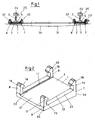
- FIG. 4 the console according to the invention 1.
- This rests with its underside 37 on the tunnel sole not shown here and comprises by means of the arms 6, 7, more precisely, the projections 17, 18 of the foot 4 of the rail 3 in a kind of click connection.
- the reference numerals 40, 41 are springs, with the reference numeral 27 is provided the net hook.
- FIG. 5 In plan view shows rail 3 and console 1 FIG. 5 , The rail 3 rests on the rail sleeper 5 and is connected via welding bolts 38, 39 and nuts 28, respectively. 30 fixed with the rail chairs 29. Before and behind the threshold 5, the four arms 6, 7, 8, 9 of the console 1 can be seen.
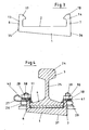
- FIG. 6 shows the ensemble of rail 3 and console 1 in side view.
- the foot 4 of the rail 3 is encompassed by the here recognizable arms 6 and 8.
- About the rail chair 29 and bolt 39 and nut 30 rail 3 and 5 threshold are fixed together.
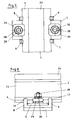
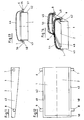
- FIG. 7 shows a console 1 in side view, the thickness of which increases greatly from page 35 to page 36. With the bottom 37 it rests on the tunnel sole, not shown here. It is in the representation according to FIG. 7 to the variant of the invention with only a pair of opposing arms, of which here the arm provided with the reference numeral 7 conceals the underlying.
- this console is 1 in FIG. 8 shown.
- the steel sleeper not shown here is additionally fixed and framed by the webs 24, 49 and 50.
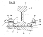
- FIG. 10 The variant of the console 1 with only a pair of oppositely positioned arms shows FIG. 10 , Only the arm 7 or by this hidden arm is present and serves to surround the foot 4 of the rail 3. This is otherwise fixed by the clamping plates 26, 29 with the welding studs 38, 39 and the nuts 28, 30. A Liner 54 off Plastic is still below the foot 4 of the rail 3 and thus between rail 4 and console. 1
- the arms are located laterally on the console 1.
- the arms 7 and 8 on the outer side 43 of the console 1 can be seen. They are perpendicular to the ground from the outside 43.
- FIG. 12 This is also in FIG. 12 shown.
- the arms 7 and 8 on the outside 43 and the arms 6 and 9 on the outside 42 are positioned so that the tension belt can be fastened between them.
- Well recognizable here is again the frame 46, consisting of the webs 48, 49 and 50.
- FIG. 13 shows the tension belt 44 installed on the arms 6 and 7. To better fix the tension belt 44 on the arms 6, 7, these have a chamfer 55, 56 and a thickening 57, 58, behind which the tension belt 44 can engage.
- FIG. 14 this variant of the console 1 in a perspective view.
- the arms 8 and 9 are of the tension belt 45, the arms 6 and 7 spanned by the tension belt 44, so that resting on the plateau 2, but not shown here threshold between the webs 48, 49, 50 positioned and in addition of the tension straps 44th and 45 is included safely.
- FIG. 15 a variant of the invention is shown, which is characterized in particular by the end strip 10, which replaces as a variant two arranged in the respective corners of the plateau arms.
- This solution is considered to be advantageous in that the surface pressure can be reduced by the compact design of the end strip 10.
- the end strip 10 is positioned opposite the arms 7 and 9 and extends here over the complete outer side 35 of the console 2. Transverse to one of its longitudinal axes 63 are located at the ends 61, 62 of the end strip 10th ramp-like transitions 64, 65 in the webs 48, 49, which in turn form a kind of connection to the oppositely positioned arms 7 and 9.
- the end strip 10 is arranged by the ramp-like transitions 64, 65 and / or by the receptacle 66, which forms them for the rail or rail tie, not shown here, corresponding to the latter.
- FIG. 16 the console 1 is shown with the end strip 10 in side view.
- the end strip 10 is in the frame 48 in the context of the ramp-like transition 64.
- the end strip 10 forms with the opposite arms 18 together the receptacle for the rail or railroad tie, not shown here.
Description
Die Erfindung betrifft eine als Unterlage von im Rahmen von Tunnelbaumaßnahmen temporär installierten Schienen dienende Konsole.The invention relates to a serving as a base of temporarily installed in the context of tunnel construction measures rails console.
Beim Einsatz von Eisenbahnen im Rahmen des Tunnelvortriebs, -ausbaus oder der Tunnelsanierung werden Schienen verlegt, die nach Abschluss der Bauarbeiten wieder demontiert werden. Dabei gilt es, Unebenheiten auf der Tunnelsohle auszugleichen. Diese bestehen insbesondere darin, dass z. B. im Tübbingausbau ein runder Abschnitt des Tunnelprofils überbrückt werden muss. Hierzu ist es notwendig, eine Art Unterbau für die Schienen vorzusehen und durch eine z.B. keilförmige Konsole einen Ausgleich zu schaffen. Als solche Konsolen dienen z. B. Holzkeile oder Konstruktionen aus Metall. Allen bisher bekannten Konsolen ist gemeinsam, dass sie sehr aufwendig bauen und den speziellen Einbaubedingungen vor Ort angepasst werden müssen, was besonders kostenaufwendig ist. Holz und Stahl bringen dabei die Nachteile mit sich, unterschiedlichen örtlichen Gegebenheiten, insbesondere den Tunnelradien, sehr schwer anpassbar zu sein. D. h. das Material muss entweder unmittelbar vor dem Einbau nachbearbeitet oder aber es müssen Keile unterschiedlichster Form und Neigung vorgehalten werden. Ein zusätzlicher Nachteil der bisher bekannten Keile besteht darin, dass diese in Hinblick auf Geräuschentwicklung problematisch sind, dass es in Folge der Belastungen auf Schienen und Keile zu Beschädigungen der Oberflächen am Tübbingstein bzw. an der Betonsohle kommt, dass Gleismaterial, Lokomotiven und Waggons einer besonders starken Belastung ausgesetzt sind und dass schließlich die Demontage beim Gleisrückbau oder beim Austausch einzelner Schwellen oder Gleisjoche sehr aufwendig ist, siehe zum Beispiel
Damit stellt sich der vorliegenden Erfindung die Aufgabe, eine als Unterlage von temporär verbauten Schienen für den Eisenbahnverkehr dienende Konsole zu schaffen, die geeignet ist, die vorgenannten Nachteile auszuräumen.Thus, the present invention has the object to provide a serving as a support of temporarily installed rails for rail transport console, which is adapted to overcome the aforementioned disadvantages.
Diese Aufgabe wird dadurch gelöst, dass die Konsole mit ihrer Unterseite auf der Tunnelsohle ruht und ein unterhalb der Schiene zu positionierendes Plateau mit ungleichmäßiger Dicke und paarweise gegenüberliegend angeordneten Armen aufweist.This object is achieved in that the console rests with its underside on the tunnel sole and has a below the rail to be positioned plateau with uneven thickness and pairwise oppositely arranged arms.
Die Konsole wird im Rahmen der Installation der Schienen unter diesen positioniert, wo sie eine besonders geeignete Auflage für die Schienen bildet. Neben dem unterhalb der Schiene und als eigentliche Auflage dienenden Plateau weist die Konsole paarweise gegenüberliegend angeordnete Arme auf. In besonders geeigneter Weise passt sich die erfindungsgemäße Konsole dabei einerseits Schiene oder Schwelle und andererseits der Tunnelsohle an. Zur Anpassung der erfindungsgemäßen Konsole an die Bedingungen vor Ort ist vorgesehen, dass das Plateau eine ungleichmäßige Dicke aufweist. Hierzu kann die Unterseite der Konsole linear schräg oder auch rund verlaufend angeordnet sein. In jedem Fall kann die Konsole sich zusätzlich, sofern sie aus einem nachgiebigen Material hergestellt ist, auch an die örtlichen Bedingungen gut anpassen.The console is positioned below the rails as part of the installation, where it forms a particularly suitable support for the rails. In addition to the below the rail and serving as a real support plateau, the console has pairs of oppositely arranged arms. In a particularly suitable manner, the console according to the invention adapts on the one hand rail or threshold and on the other hand, the tunnel sole. To adapt the console according to the invention to the conditions on site, it is provided that the plateau has an uneven thickness. For this purpose, the underside of the console can be arranged linearly inclined or even running around. In any case, the console, if made of a resilient material, can also adapt well to local conditions.
Zusätzlich ist vorgesehen, dass die Arme den Fuß der Schiene und/oder die Schienenschwelle umfassen. Damit wird der aus Konsole bzw. Schiene und/oder Schwelle bestehenden Baugruppe ein zusätzliches Maß an Stabilität verliehen, indem die Konsole nicht nur als Auflager, sondern darüber hinausgehend auch dazu dient, Schiene und/oder Schwelle von oben zu stabilisieren und Kontaktflächen zu schaffen.In addition, it is provided that the arms comprise the foot of the rail and / or the rail sleeper. Thus, the module consisting of bracket or rail and / or threshold is given an additional degree of stability by the console serves not only as a support, but beyond also to stabilize rail and / or threshold from above and to create contact surfaces.
Eine bevorzugte Variante der Erfindung sieht dabei vor, dass die Konsole mindestens zwei paarweise angeordnete Arme aufweist. Insgesamt mindestens vier Arme umfassen damit die Konsole bzw. das Plateau gleichmäßig und beidseitig von Schiene oder Schwelle.A preferred variant of the invention provides that the console has at least two arms arranged in pairs. Total at least four arms so that the console or the plateau evenly and on both sides of rail or threshold.
In diesem Sinne ist auch der Vorschlag zu verstehen, wonach die Arme an der Außenseite des Plateaus vorgesehen sind. Vorzugsweise sind sie in den vier Ecken des Plateaus bzw. der Konsole positioniert und erstrecken sich aus der Ebene des Plateaus heraus nach oben.In this sense, the proposal is to be understood, according to which the arms are provided on the outside of the plateau. Preferably, they are positioned in the four corners of the plateau or console and extend upwardly out of the plane of the plateau.
Um eine noch bessere Verbindung zwischen den Armen der Konsole und Schiene oder Schwelle herstellen zu können, ist es zweckmäßig, wenn die Arme federnd ausgebildet und/oder gelagert sind, so dass es zu einer Art Rast- oder Klickverbindung zwischen Konsole und Schiene und/oder Schwelle kommen kann. Damit ist auch eine denkbar einfache Montage von Konsole und Schiene möglich, indem die Arme gewissermaßen selbsttätig nach der Installation Schienenfuß oder Schwelle umschließen und sich quasi selbst positionieren.In order to produce an even better connection between the arms of the console and rail or threshold, it is advantageous if the arms are resilient and / or stored, so that there is a kind of snap or click connection between the console and rail and / or Threshold can come. Thus, a very simple mounting of console and rail is possible by the arms, so to speak automatically after installation rail foot or threshold enclose and virtually position themselves.
Zusätzlich ist vorgesehen, dass die Arme an ihrem oberen Ende korrespondierend zu dem Schienenfuß und/oder der Schienenschwelle ausgebildet und angeordnet sind. Damit wird erreicht, dass die Arme Schienenfuß oder Schwelle auch teilweise umfassen können, sodass es zu der beabsichtigten, besonders geeigneten Verbindung kommt. Diese ist auch insofern vorteilhaft, als dass durch den engen Kontakt zwischen Konsole und Schiene eine geräuschdämpfende Vorrichtung realisiert ist. Neben dem engen und großflächigen Kontakt zwischen Schiene und Konsole wird dies auch durch die Wahl eines entsprechend nachgiebigen und geräuschdämpfenden Materials für die Konsole gewährleistet.In addition, it is provided that the arms are formed and arranged at its upper end corresponding to the rail foot and / or the rail sleeper. This ensures that the arms may also partially include rail foot or threshold so that it comes to the intended, particularly suitable connection. This is also advantageous in that a noise-damping device is realized by the close contact between the console and rail. In addition to the narrow and large-area contact between rail and console, this is also ensured by the choice of a correspondingly resilient and noise-damping material for the console.
Die korrespondierende Ausbildung der Arme zu Schienenfuß und/oder Schwelle wird erreicht, wenn die Arme an ihrer Oberseite einen nach innen ausgerichteten Vorsprung aufweisen, der sich mit seiner Unterseite an Schienenfuß oder Schwelle anlegt.The corresponding design of the arms to the rail foot and / or threshold is achieved when the arms have on their upper side an inwardly directed projection, which applies with its underside to rail foot or threshold.
In Abwandlung der beschriebenen Variante, bei der die Arme sich senkrecht von dem Plateau erhebend an dessen Seite befinden, sieht eine andere Lösung vor, dass die Arme an der Außenseite der eigentlichen Konsole vorgesehen sind. Dort erstrecken sich die Arme zur Seite hin, also parallel zum Boden.In a modification of the variant described in which the arms are perpendicular from the plateau uplifting on the side, another solution provides that the arms are provided on the outside of the actual console. There, the arms extend to the side, ie parallel to the ground.
Eine Variante der Erfindung sieht vor, dass die Konsole an einer Seite ein Paar von Armen und an der gegenüber liegenden Seite eine korrespondierend zu der Schiene ausgebildete und sich nach oben erstreckende Abschlussleiste aufweist. Diese Variante erweist sich in Ergänzung zu der mit vier Armen in den Ecken des Plateaus dahingehend als vorteilhaft, dass die Flächenpressung niedriger ist. Insofern werden hier gewissermaßen zwei Arme auf einer Seite der Konsole durch die korrespondierend zu der Schiene ausgebildete und auf der gegenüber liegenden Seite der Konsole positionierte Abschlussleiste zur besseren Verteilung der auftretenden Kräfte ergänzt bzw. ersetzt.A variant of the invention provides that the console has on one side a pair of arms and on the opposite side a corresponding to the rail formed and upwardly extending end strip. This variant proves to be in addition to the four arms in the corners of the plateau to the effect that the surface pressure is lower. In this respect, so to speak, two arms on one side of the console are complemented or replaced by the corresponding trained to the rail and positioned on the opposite side of the console end bar for better distribution of the forces occurring.
Insbesondere ist daran gedacht, dass die Abschlussleiste an ihren Enden in quer zu ihrer Längsachse angeordnete, an der Außenseite des Plateaus angeordnete Stege übergeht. Eine Art rampenartiger Übergang erstreckt sich hierzu von der Abschlussleiste in ihrer Querrichtung zu den Stegen, die ihrerseits eine Art Verbindung zu den gegenüberliegend positionierten Armen bilden. Der Abschlussleiste kann dabei auch die Funktion einer teilweisen Einhausung für Schiene oder Schienenschwelle zukommen. Sie dient zu den Seiten, wie auch teilweise nach oben durch ihre korrespondierende Ausbildung als deren zusätzliche Führung.In particular, it is envisaged that the end strip at its ends in transversely to its longitudinal axis arranged, arranged on the outside of the plateau webs merges. A kind of ramp-like transition extends to this end of the end strip in its transverse direction to the webs, which in turn form a kind of connection to the oppositely positioned arms. The end bar can also serve the function of a partial enclosure for rail or rail sleeper. It serves to the sides, as well as partly upwards by their corresponding training as their additional guidance.
Vorgesehen ist außerdem, dass die paarweise gegenüberliegend angeordneten Arme oder Arme und Abschlussleiste mit einem Spanngurt miteinander verbunden werden können. Durch diesen Spanngurt wird erreicht, dass zwischen Konsole einerseits und Schiene oder Schwelle andererseits entsprechende Kontaktflächen bestehen. Bei der Ausführungsform der Erfindung mit zwei paarweise einander gegenüber liegend angeordneten Armen sind jeweils im Bereich der Enden der Konsole solche Arme mit Spanngurten positioniert.It is also envisaged that the pairs of oppositely arranged arms or arms and end strip can be connected to each other with a tension belt. By means of this tension belt, it is achieved that corresponding contact surfaces exist between the console on the one hand and the rail or the threshold, on the other hand. In the embodiment of the invention with two pairs of oppositely arranged arms each such arms are positioned with straps in the region of the ends of the console.
Ein weiterer Vorschlag sieht vor, dass das Plateau einen korrespondierend zu einer Schienenschwelle ausgebildeten Rahmen aufweist. Dieser Rahmen ist vorzugsweise durch an zwei Längsseiten und einer Stirnseite angeordnete Stege gebildet und kann damit als Einfassung einer Schienenschwelle dienen.Another proposal provides that the plateau has a frame formed corresponding to a rail tie. This frame is preferably formed by webs arranged on two longitudinal sides and one end face and can thus serve as a border of a rail sleeper.
Eine zusätzliche Ausführungsform sieht vor, dass das Plateau an seiner Oberseite mindestens eine Abstufung aufweist. Zweckmäßigerweise ist auf den gegenüberliegenden Seiten des Plateaus eine solche, sich an der Innenseite der Klickarme erstreckende Abstufung vorgesehen, so dass sich dort eine Art eingenutetes Schwellenbett ausbildet. Primärer Zweck dieser Abstufungen ist es, die im Zusammenhang mit dem Fahren der Züge entstehenden dynamischen Kräfte, insbesondere die Bremskräfte aufzunehmen.An additional embodiment provides that the plateau has at least one step on its upper side. Appropriately, on the opposite sides of the plateau such, extending on the inside of the click arms grading is provided so that there forms a kind of well-sleeper bed. The primary purpose of these gradations is to absorb the dynamic forces associated with driving the trains, in particular the braking forces.
Es ist empfehlenswert, dass die Konsole einteilig hergestellt ist, was in Bezug auf mehrere Aspekte vorteilhaft ist. So ist etwa die Montage der Konsolen unterhalb der Gleise oder Schwellen besonders einfach, zumal hierfür keinerlei Werkzeug notwendig ist. Ebenso sind separate Befestigungsmittel entbehrlich. Weiterhin erweist sich diese Einteiligkeit der Konsole als vorteilhaft in Hinblick auf die Geräuschdämpfung, die Möglichkeit der Demontage oder Auswechslung oder geringen Verschleiß.It is recommended that the console be made in one piece, which is advantageous in several aspects. Thus, for example, the assembly of the consoles below the tracks or sleepers is particularly easy, especially since no tools are necessary for this purpose. Likewise, separate fasteners are unnecessary. Furthermore, this one-piece design of the console proves to be advantageous in terms of noise reduction, the possibility of disassembly or replacement or low wear.
Es wurde bereits darauf hingewiesen, dass eine gewisse Nachgiebigkeit für die Konsole zweckmäßig ist. Dies bezieht sich einerseits auf die Unterseite der Konsole und die Anpassung an die Tunnelsohle, insbesondere den Tunnelradius und andererseits auf die Oberseite und die Anpassung an Schienenfuß und/oder Schwelle sowie die Rast- oder Klickverbindung durch die Arme. Von daher wird empfohlen, dass die Konsole aus Kunststoff oder Kautschuk, insbesondere der Shore-Härte 80 A für Kunststoff oder der Shore-Härte 40 D für Kautschuk hergestellt ist.It has already been pointed out that a certain flexibility for the console is appropriate. This refers on the one hand to the underside of the console and the adaptation to the tunnel sole, in particular the tunnel radius and on the other hand on the top and the adaptation to rail and / or threshold and the snap or click connection through the arms. It is therefore recommended that the console be made of plastic or rubber, in particular the Shore hardness 80 A for plastic or the Shore hardness 40 D for rubber.
Um eine bessere Verbindung zwischen Konsole und aufliegender Stahlschwelle zu erreichen, ist vorgesehen, dass die Konsole an ihrer Oberseite eine Klebefläche aufweist. Über die Klebeschicht an der Oberseite der Konsole wird diese zusätzlich auf der Tunnelsohle fixiert. Durch die zuvor beschriebene rahmenartige Ausbildung des die Kontaktfläche zwischen Konsole und Schienenschwelle bildenden Plateaus wird diese Klebefläche zusätzlich nur relativ gering mechanisch belastet, so dass sie ihre volle Wirkung entfalten kann.In order to achieve a better connection between the console and resting steel sleeper, it is provided that the console has an adhesive surface on its upper side. The adhesive layer on the top of the console additionally fixes it on the tunnel sole. Due to the above-described frame-like design of the contact surface between the console and rail sleeper forming plateau, this adhesive surface is additionally only relatively low mechanical load, so that they can develop their full effect.
Die Erfindung zeichnet sich insbesondere dadurch aus, dass eine als Unterlage von temporär installierten Schienen für den Eisenbahnverkehr dienende Konsole geschaffen ist, deren Einsatz gerade im Rahmen von Tunnelbaumaßnahmen sinnvoll ist. Die Kompaktheit der aus einem Plateau und den paarweise gegenüberliegend angeordneten zwei, vier oder mehr Armen bestehenden Konsole und ihrer Verbindung zu Schiene und/oder Schwelle verleiht dem System besondere Vorteile wie Geräuschreduzierung, exakte Anpassung an den Tunnelradius, das Ausbleiben von Oberflächenbeschädigungen am Tübbingstein bzw. der Betonsohle, höhere Standzeiten des rollenden Materials in Form von Lokomotiven und Waggons durch Dämpfung der Schläge und Schwingungen und damit einhergehenden geringeren Instandhaltungsaufwand, einfache und schnelle Montage im Werk oder auf der Tunnelbaustelle, Wiederverwendbarkeit, Schonung des Gleismaterials, einfache Demontage bei Gleisrückbau oder einfacher Wechsel bei Entgleisung einzelner Schwellen bzw. Gleisjoche sowie einer vollflächigen Ableitung der anfallenden Bremskräfte durch das eingenutete Schwellenbett der Konsole und ein flexibel einsetzbares Material in Hinblick auf Entflammbarkeit oder die Vermeidung der Entstehung von Russpartikeln.The invention is characterized in particular by the fact that a serving as a base of temporarily installed rails for rail transport console is created, their use is useful in the context of tunnel construction measures. The compactness of the consisting of a plateau and the pairs arranged opposite two, four or more arms console and their connection to rail and / or threshold gives the system special advantages such as noise reduction, exact adaptation to the tunnel radius, the absence of surface damage to the tubbing stone or the concrete base, longer life of the rolling stock in the form of locomotives and wagons by damping the shocks and vibrations and associated lower maintenance costs, easy and quick installation in the factory or on the tunnel construction site, reusability, protection of the track material, easy dismantling at track dismantling or simple change derailment of individual sleepers or track bumps as well as a full-surface discharge of the resulting braking forces through the grooved sleeper bed of the console and a flexible material with regard to flammability or the avoidance of En formation of soot particles.
Weitere Einzelheiten und Vorteile des Erfindungsgegenstandes ergeben sich aus der nachfolgenden Beschreibung der zugehörigen Zeichnung, in der ein bevorzugtes Ausführungsbeispiel mit den dazu notwendigen Einzelheiten und Einzelteilen dargestellt ist. Es zeigen:
Figur 1- ein Gleis im Querschnitt,
Figur 2- eine Konsole in perspektivischer Ansicht,
Figur 3- eine Konsole in Seitenansicht,
Figur 4- eine installierte Konsole im Schnitt,
Figur 5- eine installierte Konsole in Draufsicht,
Figur 6- eine installierte Konsole in Seitenansicht,
Figur 7- eine andere Konsole in Seitenansicht,
Figur 8- die Konsole gemäß
Fig. 7 in Draufsicht, Figur 9- die Konsole gemäß
Fig. 7 in perspektivischer Ansicht, Figur 10- eine Variante zu
Figur 4 , Figur 11- eine Konsole mit seitlichen Armen in Seitenansicht,
Figur 12- die Konsole gemäß
Fig. 11 in Draufsicht, Figur 13- die Konsole gemäß
Fig. 11 mit Spanngurt in Stirnansicht, Figur 14- die Konsole gemäß
Fig. 13 in perspektivischer Ansicht, Figur 15- eine Konsole mit Abschlussleiste in perspektivischer Ansicht und
Figur 16- eine Konsole mit Abschlussleiste in Seitenansicht.
- FIG. 1
- a track in cross section,
- FIG. 2
- a console in perspective view,
- FIG. 3
- a console in side view,
- FIG. 4
- an installed console on average,
- FIG. 5
- an installed console in plan view,
- FIG. 6
- an installed console in side view,
- FIG. 7
- another console in side view,
- FIG. 8
- the console according to
Fig. 7 in plan view, - FIG. 9
- the console according to
Fig. 7 in perspective view, - FIG. 10
- a variant too
FIG. 4 . - FIG. 11
- a console with side arms in side view,
- FIG. 12
- the console according to
Fig. 11 in plan view, - FIG. 13
- the console according to
Fig. 11 with tension belt in front view, - FIG. 14
- the console according to
Fig. 13 in perspective view, - FIG. 15
- a console with closing bar in perspective view and
- FIG. 16
- a console with end bar in side view.
In
Dies ist auch besonders gut in
Nochmals gezeigt ist die Konsole 1 in
Im installierten Zustand zeigt
In Draufsicht zeigt Schiene 3 und Konsole 1
Außerdem zeigt
In Ansicht von unten ist diese Konsole 1 in
In
Die Variante der Konsole 1 mit nur einem Paar von einander gegenüberliegend positionierten Armen zeigt
Gemäß
Dies ist auch in
Die Draufsicht in
Schließlich zeigt
In
In
Claims (17)
- A bracket serving as a base for rails laid temporarily as part of tunnel building work,
characterized
in that the bracket (1) rests with its underside on the base of the tunnel and has a plateau (2) under the rail (3) for positioning purposes with an uneven thickness and opposing arms arranged in pairs (6, 7, 8, 9). - The bracket according to Claim 1,
characterized
in that the arms (6, 7, 8, 9) comprise the foot (4) of the rail (3) and/or the rail sleepers (5). - The bracket according to Claim 1,
characterized
in that the bracket (1) has at least two arms arranged in pairs (6, 7, 8, 9). - The bracket according to Claim 1,
characterized
in that the arms (6, 7, 8, 9) are provided on the outer side (11, 12) of the plateau (2). - The bracket according to Claim 1,
characterized
in that the arms (6, 7, 8, 9) are formed sprung and/or supported on bearings. - The bracket according to Claim 1,
characterized
in that the arms (6, 7, 8, 9) are on their upper end (13, 14, 15, 16) formed and arranged corresponding to the rail foot (4) and/or the rail sleepers (5). - The bracket according to Claim 6,
characterized
in that the arms (6, 7, 8, 9) have on their upper side (13, 14, 15, 16) a projection directed inwards (17, 18, 19, 20). - The bracket according to Claim 1,
characterized
in that the arms (6, 7, 8, 9) are provided on the outer side (42, 43) of the bracket (1). - The bracket according to Claim 1,
characterized
in that the bracket (1) has a pair of arms (7, 9) on one side (36) and a termination strip (10) on the opposite side (35) which corresponds to the rail (3) and which extends upwards. - The bracket according to Claim 9,
characterized
in that the termination strip (10) gets over in stems (59, 60) arranged at its ends (61, 62) transverse to its longitudinal axis (63) on the outer side (11, 12) of the plateau (2). - The bracket according to Claim 1,
characterized
in that the opposing arms (6, 7, 8, 9) arranged in pairs are connected together by a lashing strap (44, 45). - The bracket according to Claim 1,
characterized
in that the plateau (2) has a frame (46) formed to correspond to a rail sleeper (5). - The bracket according to Claim 1,
characterized
in that the plateau (2) has at least one step (22, 23) on its upper side (21). - The bracket according to Claim 1,
characterized
in that the bracket (1) is manufactured as one piece. - The bracket according to Claim 1,
characterized
in that the bracket (1) is made out of plastic or rubber. - The bracket according to Claim 15,
characterized
in that the bracket (1) is made out of plastic with a Shore hardness of 80 A or a rubber with a Shore hardness of 40 D. - The bracket according to Claim 1,
characterized
in that the bracket (1) has an adhesive surface (47) on its upper side (21).
Applications Claiming Priority (1)
| Application Number | Priority Date | Filing Date | Title |
|---|---|---|---|
| DE200710061008 DE102007061008A1 (en) | 2007-12-18 | 2007-12-18 | Console for temporarily installed rails |
Publications (3)
| Publication Number | Publication Date |
|---|---|
| EP2072681A2 EP2072681A2 (en) | 2009-06-24 |
| EP2072681A3 EP2072681A3 (en) | 2011-03-23 |
| EP2072681B1 true EP2072681B1 (en) | 2013-01-09 |
Family
ID=40460004
Family Applications (1)
| Application Number | Title | Priority Date | Filing Date |
|---|---|---|---|
| EP20080019474 Active EP2072681B1 (en) | 2007-12-18 | 2008-11-07 | Console for temporarily installed rails |
Country Status (3)
| Country | Link |
|---|---|
| EP (1) | EP2072681B1 (en) |
| DE (1) | DE102007061008A1 (en) |
| ES (1) | ES2402228T3 (en) |
Family Cites Families (7)
| Publication number | Priority date | Publication date | Assignee | Title |
|---|---|---|---|---|
| DE105110C (en) * | ||||
| US1431296A (en) * | 1921-05-16 | 1922-10-10 | Elmer E Fox | Tie plate |
| US1577830A (en) * | 1924-08-26 | 1926-03-23 | Minna Kruttschnitt E | Railway tie plate |
| DE816705C (en) * | 1950-06-01 | 1951-10-11 | Wilhelm Wichmann | Hanger bracket |
| GB2086966A (en) * | 1980-11-01 | 1982-05-19 | Serni Ltd | Railway sleepers with rail clamping devices |
| DE3408597C2 (en) * | 1984-03-09 | 1986-03-13 | Hoesch Ag, 4600 Dortmund | Concrete sleeper with rail fastenings |
| DE19801584A1 (en) * | 1998-01-19 | 1999-07-29 | Schreck Mieves Gmbh | Guide rail mounting on Vignoles rail |
-
2007
- 2007-12-18 DE DE200710061008 patent/DE102007061008A1/en not_active Withdrawn
-
2008
- 2008-11-07 EP EP20080019474 patent/EP2072681B1/en active Active
- 2008-11-07 ES ES08019474T patent/ES2402228T3/en active Active
Also Published As
| Publication number | Publication date |
|---|---|
| ES2402228T3 (en) | 2013-04-29 |
| DE102007061008A1 (en) | 2009-06-25 |
| EP2072681A3 (en) | 2011-03-23 |
| EP2072681A2 (en) | 2009-06-24 |
Similar Documents
| Publication | Publication Date | Title |
|---|---|---|
| DE202006020567U1 (en) | System for fastening a rail | |
| EP1866481B1 (en) | Rail bearing | |
| DE102009005439A1 (en) | Miniscan wall for threshold tracks | |
| CH620004A5 (en) | Railway sleeper | |
| EP3744893A1 (en) | Rail fixing system | |
| DE19931048A1 (en) | Track for rail-bound vehicles and soundproofing element therefor | |
| DE1964039A1 (en) | Elastic element for mounting rails or sleepers | |
| AT409641B (en) | Ballastless superstructure with prefabricated concrete support plates as well as a procedure for the replacement of the same | |
| AT404266B (en) | RAILWAY RAILWAYS | |
| EP2072681B1 (en) | Console for temporarily installed rails | |
| EP0542782A1 (en) | Railway level crossing. | |
| DE2718665A1 (en) | Railway track steel sleeper - has ribbed plates beside lengthways groove with gap for shaft of fixing bolt | |
| EP1767696B1 (en) | Railway sleeper | |
| CH641861A5 (en) | Arrangement for re-constructing a boundary path next to the ballast bed of a railway embankment | |
| DE1534108A1 (en) | Track construction | |
| WO2018215033A2 (en) | Rail assembly for rail vehicles having flanged wheels | |
| DE202007017646U1 (en) | Console for temporarily installed rails | |
| EP1830002B1 (en) | Track structure adapted for tramways | |
| DE815047C (en) | Railroad track with side rails arranged along the outside of each track rail to enable the track to be driven on even with rubber-tired vehicles | |
| DE19501696A1 (en) | Low-noise track body | |
| DE10333838B4 (en) | Device for adjusting a track grate | |
| DE4325869C2 (en) | Fixed track for rail-bound traffic | |
| DE4430881A1 (en) | Elastic bearing system for rail tracks, e.g. for railways, tram and crane tracks etc | |
| DE565544C (en) | Railway sleeper with a chair plate embedded in the sleeper body | |
| DE19961391A1 (en) | Fixture arrangement, particularly for sound protection plates, between or next to rails of railway track involves fixture body secured on at least one sleeper or track support plate |
Legal Events
| Date | Code | Title | Description |
|---|---|---|---|
| PUAI | Public reference made under article 153(3) epc to a published international application that has entered the european phase |
Free format text: ORIGINAL CODE: 0009012 |
|
| AK | Designated contracting states |
Kind code of ref document: A2 Designated state(s): AT BE BG CH CY CZ DE DK EE ES FI FR GB GR HR HU IE IS IT LI LT LU LV MC MT NL NO PL PT RO SE SI SK TR |
|
| AX | Request for extension of the european patent |
Extension state: AL BA MK RS |
|
| PUAL | Search report despatched |
Free format text: ORIGINAL CODE: 0009013 |
|
| AK | Designated contracting states |
Kind code of ref document: A3 Designated state(s): AT BE BG CH CY CZ DE DK EE ES FI FR GB GR HR HU IE IS IT LI LT LU LV MC MT NL NO PL PT RO SE SI SK TR |
|
| AX | Request for extension of the european patent |
Extension state: AL BA MK RS |
|
| RIC1 | Information provided on ipc code assigned before grant |
Ipc: E01B 23/00 20060101ALI20110217BHEP Ipc: E01B 26/00 20060101ALI20110217BHEP Ipc: E01B 9/68 20060101ALI20110217BHEP Ipc: E01B 2/00 20060101AFI20090331BHEP |
|
| 17P | Request for examination filed |
Effective date: 20110923 |
|
| AKX | Designation fees paid |
Designated state(s): AT BE BG CH CY CZ DE DK EE ES FI FR GB GR HR HU IE IS IT LI LT LU LV MC MT NL NO PL PT RO SE SI SK TR |
|
| GRAP | Despatch of communication of intention to grant a patent |
Free format text: ORIGINAL CODE: EPIDOSNIGR1 |
|
| GRAS | Grant fee paid |
Free format text: ORIGINAL CODE: EPIDOSNIGR3 |
|
| GRAA | (expected) grant |
Free format text: ORIGINAL CODE: 0009210 |
|
| AK | Designated contracting states |
Kind code of ref document: B1 Designated state(s): AT BE BG CH CY CZ DE DK EE ES FI FR GB GR HR HU IE IS IT LI LT LU LV MC MT NL NO PL PT RO SE SI SK TR |
|
| REG | Reference to a national code |
Ref country code: GB Ref legal event code: FG4D Free format text: NOT ENGLISH |
|
| REG | Reference to a national code |
Ref country code: CH Ref legal event code: EP Ref country code: AT Ref legal event code: REF Ref document number: 592843 Country of ref document: AT Kind code of ref document: T Effective date: 20130115 |
|
| REG | Reference to a national code |
Ref country code: IE Ref legal event code: FG4D Free format text: LANGUAGE OF EP DOCUMENT: GERMAN |
|
| REG | Reference to a national code |
Ref country code: DE Ref legal event code: R096 Ref document number: 502008009050 Country of ref document: DE Effective date: 20130307 |
|
| REG | Reference to a national code |
Ref country code: CH Ref legal event code: NV Representative=s name: ALDO ROEMPLER PATENTANWALT, CH |
|
| REG | Reference to a national code |
Ref country code: NL Ref legal event code: T3 |
|
| REG | Reference to a national code |
Ref country code: ES Ref legal event code: FG2A Ref document number: 2402228 Country of ref document: ES Kind code of ref document: T3 Effective date: 20130429 |
|
| PG25 | Lapsed in a contracting state [announced via postgrant information from national office to epo] |
Ref country code: SI Free format text: LAPSE BECAUSE OF FAILURE TO SUBMIT A TRANSLATION OF THE DESCRIPTION OR TO PAY THE FEE WITHIN THE PRESCRIBED TIME-LIMIT Effective date: 20130109 |
|
| REG | Reference to a national code |
Ref country code: LT Ref legal event code: MG4D |
|
| PG25 | Lapsed in a contracting state [announced via postgrant information from national office to epo] |
Ref country code: LT Free format text: LAPSE BECAUSE OF FAILURE TO SUBMIT A TRANSLATION OF THE DESCRIPTION OR TO PAY THE FEE WITHIN THE PRESCRIBED TIME-LIMIT Effective date: 20130109 Ref country code: NO Free format text: LAPSE BECAUSE OF FAILURE TO SUBMIT A TRANSLATION OF THE DESCRIPTION OR TO PAY THE FEE WITHIN THE PRESCRIBED TIME-LIMIT Effective date: 20130409 Ref country code: IS Free format text: LAPSE BECAUSE OF FAILURE TO SUBMIT A TRANSLATION OF THE DESCRIPTION OR TO PAY THE FEE WITHIN THE PRESCRIBED TIME-LIMIT Effective date: 20130509 Ref country code: BG Free format text: LAPSE BECAUSE OF FAILURE TO SUBMIT A TRANSLATION OF THE DESCRIPTION OR TO PAY THE FEE WITHIN THE PRESCRIBED TIME-LIMIT Effective date: 20130409 Ref country code: SE Free format text: LAPSE BECAUSE OF FAILURE TO SUBMIT A TRANSLATION OF THE DESCRIPTION OR TO PAY THE FEE WITHIN THE PRESCRIBED TIME-LIMIT Effective date: 20130109 |
|
| PG25 | Lapsed in a contracting state [announced via postgrant information from national office to epo] |
Ref country code: FI Free format text: LAPSE BECAUSE OF FAILURE TO SUBMIT A TRANSLATION OF THE DESCRIPTION OR TO PAY THE FEE WITHIN THE PRESCRIBED TIME-LIMIT Effective date: 20130109 Ref country code: LV Free format text: LAPSE BECAUSE OF FAILURE TO SUBMIT A TRANSLATION OF THE DESCRIPTION OR TO PAY THE FEE WITHIN THE PRESCRIBED TIME-LIMIT Effective date: 20130109 Ref country code: GR Free format text: LAPSE BECAUSE OF FAILURE TO SUBMIT A TRANSLATION OF THE DESCRIPTION OR TO PAY THE FEE WITHIN THE PRESCRIBED TIME-LIMIT Effective date: 20130410 Ref country code: PT Free format text: LAPSE BECAUSE OF FAILURE TO SUBMIT A TRANSLATION OF THE DESCRIPTION OR TO PAY THE FEE WITHIN THE PRESCRIBED TIME-LIMIT Effective date: 20130509 Ref country code: PL Free format text: LAPSE BECAUSE OF FAILURE TO SUBMIT A TRANSLATION OF THE DESCRIPTION OR TO PAY THE FEE WITHIN THE PRESCRIBED TIME-LIMIT Effective date: 20130109 |
|
| PG25 | Lapsed in a contracting state [announced via postgrant information from national office to epo] |
Ref country code: HR Free format text: LAPSE BECAUSE OF FAILURE TO SUBMIT A TRANSLATION OF THE DESCRIPTION OR TO PAY THE FEE WITHIN THE PRESCRIBED TIME-LIMIT Effective date: 20130109 |
|
| PG25 | Lapsed in a contracting state [announced via postgrant information from national office to epo] |
Ref country code: EE Free format text: LAPSE BECAUSE OF FAILURE TO SUBMIT A TRANSLATION OF THE DESCRIPTION OR TO PAY THE FEE WITHIN THE PRESCRIBED TIME-LIMIT Effective date: 20130109 Ref country code: CZ Free format text: LAPSE BECAUSE OF FAILURE TO SUBMIT A TRANSLATION OF THE DESCRIPTION OR TO PAY THE FEE WITHIN THE PRESCRIBED TIME-LIMIT Effective date: 20130109 Ref country code: RO Free format text: LAPSE BECAUSE OF FAILURE TO SUBMIT A TRANSLATION OF THE DESCRIPTION OR TO PAY THE FEE WITHIN THE PRESCRIBED TIME-LIMIT Effective date: 20130109 Ref country code: SK Free format text: LAPSE BECAUSE OF FAILURE TO SUBMIT A TRANSLATION OF THE DESCRIPTION OR TO PAY THE FEE WITHIN THE PRESCRIBED TIME-LIMIT Effective date: 20130109 Ref country code: DK Free format text: LAPSE BECAUSE OF FAILURE TO SUBMIT A TRANSLATION OF THE DESCRIPTION OR TO PAY THE FEE WITHIN THE PRESCRIBED TIME-LIMIT Effective date: 20130109 |
|
| PLBE | No opposition filed within time limit |
Free format text: ORIGINAL CODE: 0009261 |
|
| STAA | Information on the status of an ep patent application or granted ep patent |
Free format text: STATUS: NO OPPOSITION FILED WITHIN TIME LIMIT |
|
| PG25 | Lapsed in a contracting state [announced via postgrant information from national office to epo] |
Ref country code: CY Free format text: LAPSE BECAUSE OF FAILURE TO SUBMIT A TRANSLATION OF THE DESCRIPTION OR TO PAY THE FEE WITHIN THE PRESCRIBED TIME-LIMIT Effective date: 20130109 |
|
| 26N | No opposition filed |
Effective date: 20131010 |
|
| REG | Reference to a national code |
Ref country code: DE Ref legal event code: R097 Ref document number: 502008009050 Country of ref document: DE Effective date: 20131010 |
|
| BERE | Be: lapsed |
Owner name: VOESTALPINE KLOCKNER BAHNTECHNIK G.M.B.H. Effective date: 20131130 |
|
| PG25 | Lapsed in a contracting state [announced via postgrant information from national office to epo] |
Ref country code: MC Free format text: LAPSE BECAUSE OF FAILURE TO SUBMIT A TRANSLATION OF THE DESCRIPTION OR TO PAY THE FEE WITHIN THE PRESCRIBED TIME-LIMIT Effective date: 20130109 |
|
| REG | Reference to a national code |
Ref country code: IE Ref legal event code: MM4A |
|
| PG25 | Lapsed in a contracting state [announced via postgrant information from national office to epo] |
Ref country code: BE Free format text: LAPSE BECAUSE OF NON-PAYMENT OF DUE FEES Effective date: 20131130 |
|
| PG25 | Lapsed in a contracting state [announced via postgrant information from national office to epo] |
Ref country code: IE Free format text: LAPSE BECAUSE OF NON-PAYMENT OF DUE FEES Effective date: 20131107 |
|
| PG25 | Lapsed in a contracting state [announced via postgrant information from national office to epo] |
Ref country code: TR Free format text: LAPSE BECAUSE OF FAILURE TO SUBMIT A TRANSLATION OF THE DESCRIPTION OR TO PAY THE FEE WITHIN THE PRESCRIBED TIME-LIMIT Effective date: 20130109 |
|
| PG25 | Lapsed in a contracting state [announced via postgrant information from national office to epo] |
Ref country code: LU Free format text: LAPSE BECAUSE OF NON-PAYMENT OF DUE FEES Effective date: 20131107 Ref country code: HU Free format text: LAPSE BECAUSE OF FAILURE TO SUBMIT A TRANSLATION OF THE DESCRIPTION OR TO PAY THE FEE WITHIN THE PRESCRIBED TIME-LIMIT; INVALID AB INITIO Effective date: 20081107 |
|
| PG25 | Lapsed in a contracting state [announced via postgrant information from national office to epo] |
Ref country code: MT Free format text: LAPSE BECAUSE OF FAILURE TO SUBMIT A TRANSLATION OF THE DESCRIPTION OR TO PAY THE FEE WITHIN THE PRESCRIBED TIME-LIMIT Effective date: 20130109 |
|
| REG | Reference to a national code |
Ref country code: FR Ref legal event code: PLFP Year of fee payment: 8 |
|
| PGFP | Annual fee paid to national office [announced via postgrant information from national office to epo] |
Ref country code: IT Payment date: 20151124 Year of fee payment: 8 |
|
| PGFP | Annual fee paid to national office [announced via postgrant information from national office to epo] |
Ref country code: ES Payment date: 20151221 Year of fee payment: 8 Ref country code: FR Payment date: 20151130 Year of fee payment: 8 Ref country code: NL Payment date: 20151125 Year of fee payment: 8 |
|
| REG | Reference to a national code |
Ref country code: NL Ref legal event code: MM Effective date: 20161201 |
|
| REG | Reference to a national code |
Ref country code: FR Ref legal event code: ST Effective date: 20170731 |
|
| PG25 | Lapsed in a contracting state [announced via postgrant information from national office to epo] |
Ref country code: NL Free format text: LAPSE BECAUSE OF NON-PAYMENT OF DUE FEES Effective date: 20161201 |
|
| PG25 | Lapsed in a contracting state [announced via postgrant information from national office to epo] |
Ref country code: FR Free format text: LAPSE BECAUSE OF NON-PAYMENT OF DUE FEES Effective date: 20161130 Ref country code: IT Free format text: LAPSE BECAUSE OF NON-PAYMENT OF DUE FEES Effective date: 20161107 |
|
| PG25 | Lapsed in a contracting state [announced via postgrant information from national office to epo] |
Ref country code: ES Free format text: LAPSE BECAUSE OF NON-PAYMENT OF DUE FEES Effective date: 20161108 |
|
| REG | Reference to a national code |
Ref country code: ES Ref legal event code: FD2A Effective date: 20181121 |
|
| REG | Reference to a national code |
Representative=s name: PATENTANWAELTE SCHULTE & SCHULTE, DE Ref country code: DE Ref legal event code: R082 Ref document number: 502008009050 Country of ref document: DE Ref country code: DE Ref legal event code: R081 Ref document number: 502008009050 Country of ref document: DE Owner name: VOESTALPINE VAE GMBH, AT Free format text: FORMER OWNER: VOESTALPINE KLOECKNER BAHNTECHNIK GMBH, 47057 DUISBURG, DE |
|
| REG | Reference to a national code |
Ref country code: DE Ref legal event code: R082 Ref document number: 502008009050 Country of ref document: DE Representative=s name: PATENTANWAELTE SCHULTE & SCHULTE, DE |
|
| REG | Reference to a national code |
Ref country code: CH Ref legal event code: PUE Owner name: VOESTALPINE VAE GMBH, AT Free format text: FORMER OWNER: VOESTALPINE KLOECKNER BAHNTECHNIK GMBH, DE |
|
| REG | Reference to a national code |
Ref country code: GB Ref legal event code: 732E Free format text: REGISTERED BETWEEN 20190314 AND 20190320 |
|
| REG | Reference to a national code |
Ref country code: AT Ref legal event code: PC Ref document number: 592843 Country of ref document: AT Kind code of ref document: T Owner name: VOESTALPINE VAE GMBH, AT Effective date: 20190328 |
|
| PGFP | Annual fee paid to national office [announced via postgrant information from national office to epo] |
Ref country code: GB Payment date: 20231123 Year of fee payment: 16 |
|
| PGFP | Annual fee paid to national office [announced via postgrant information from national office to epo] |
Ref country code: DE Payment date: 20231121 Year of fee payment: 16 Ref country code: CH Payment date: 20231202 Year of fee payment: 16 Ref country code: AT Payment date: 20231121 Year of fee payment: 16 |