EP2072251B1 - Dampening system - Google Patents
Dampening system Download PDFInfo
- Publication number
- EP2072251B1 EP2072251B1 EP09153642A EP09153642A EP2072251B1 EP 2072251 B1 EP2072251 B1 EP 2072251B1 EP 09153642 A EP09153642 A EP 09153642A EP 09153642 A EP09153642 A EP 09153642A EP 2072251 B1 EP2072251 B1 EP 2072251B1
- Authority
- EP
- European Patent Office
- Prior art keywords
- roller
- roll
- forme cylinder
- dampening
- applying
- Prior art date
- Legal status (The legal status is an assumption and is not a legal conclusion. Google has not performed a legal analysis and makes no representation as to the accuracy of the status listed.)
- Expired - Lifetime
Links
- 238000007639 printing Methods 0.000 claims abstract description 35
- 230000032258 transport Effects 0.000 claims description 6
- 238000012505 colouration Methods 0.000 claims 4
- 230000008859 change Effects 0.000 abstract description 7
- 238000000034 method Methods 0.000 abstract description 4
- 230000008569 process Effects 0.000 abstract description 4
- 238000013016 damping Methods 0.000 abstract 3
- 238000004519 manufacturing process Methods 0.000 description 13
- KFZMGEQAYNKOFK-UHFFFAOYSA-N Isopropanol Chemical compound CC(C)O KFZMGEQAYNKOFK-UHFFFAOYSA-N 0.000 description 6
- 238000007598 dipping method Methods 0.000 description 6
- 239000000463 material Substances 0.000 description 6
- 238000011144 upstream manufacturing Methods 0.000 description 6
- XLYOFNOQVPJJNP-UHFFFAOYSA-N water Substances O XLYOFNOQVPJJNP-UHFFFAOYSA-N 0.000 description 5
- 230000005540 biological transmission Effects 0.000 description 4
- 229920001971 elastomer Polymers 0.000 description 4
- 238000007645 offset printing Methods 0.000 description 4
- 238000005096 rolling process Methods 0.000 description 4
- 239000007921 spray Substances 0.000 description 4
- 239000000203 mixture Substances 0.000 description 3
- VYZAMTAEIAYCRO-UHFFFAOYSA-N Chromium Chemical compound [Cr] VYZAMTAEIAYCRO-UHFFFAOYSA-N 0.000 description 2
- 230000006978 adaptation Effects 0.000 description 2
- 239000000919 ceramic Substances 0.000 description 2
- 229910052804 chromium Inorganic materials 0.000 description 2
- 239000011651 chromium Substances 0.000 description 2
- 230000008878 coupling Effects 0.000 description 2
- 238000010168 coupling process Methods 0.000 description 2
- 238000005859 coupling reaction Methods 0.000 description 2
- 238000001035 drying Methods 0.000 description 2
- 239000013536 elastomeric material Substances 0.000 description 2
- 239000003973 paint Substances 0.000 description 2
- 239000000758 substrate Substances 0.000 description 2
- LFQSCWFLJHTTHZ-UHFFFAOYSA-N Ethanol Chemical compound CCO LFQSCWFLJHTTHZ-UHFFFAOYSA-N 0.000 description 1
- 239000004909 Moisturizer Substances 0.000 description 1
- 239000004959 Rilsan Substances 0.000 description 1
- 238000010521 absorption reaction Methods 0.000 description 1
- 230000008901 benefit Effects 0.000 description 1
- 238000006243 chemical reaction Methods 0.000 description 1
- 239000003795 chemical substances by application Substances 0.000 description 1
- 239000011248 coating agent Substances 0.000 description 1
- 238000000576 coating method Methods 0.000 description 1
- 239000003086 colorant Substances 0.000 description 1
- 238000009826 distribution Methods 0.000 description 1
- 239000000806 elastomer Substances 0.000 description 1
- 230000001804 emulsifying effect Effects 0.000 description 1
- 238000003912 environmental pollution Methods 0.000 description 1
- 238000011156 evaluation Methods 0.000 description 1
- 230000002349 favourable effect Effects 0.000 description 1
- 238000007654 immersion Methods 0.000 description 1
- 230000007246 mechanism Effects 0.000 description 1
- 239000007769 metal material Substances 0.000 description 1
- 230000001333 moisturizer Effects 0.000 description 1
- 239000004033 plastic Substances 0.000 description 1
- 239000000126 substance Substances 0.000 description 1
Images

Classifications
-
- B—PERFORMING OPERATIONS; TRANSPORTING
- B41—PRINTING; LINING MACHINES; TYPEWRITERS; STAMPS
- B41F—PRINTING MACHINES OR PRESSES
- B41F7/00—Rotary lithographic machines
- B41F7/20—Details
- B41F7/24—Damping devices
- B41F7/36—Inking-rollers serving also to apply ink repellants
-
- B—PERFORMING OPERATIONS; TRANSPORTING
- B41—PRINTING; LINING MACHINES; TYPEWRITERS; STAMPS
- B41F—PRINTING MACHINES OR PRESSES
- B41F7/00—Rotary lithographic machines
- B41F7/20—Details
- B41F7/24—Damping devices
- B41F7/26—Damping devices using transfer rollers
Definitions
- the invention relates to a dampening unit according to the preamble of claim 1.
- a dampening unit in which a dampening solution from a fountain solution receiving immersion roller and at least one standing with the fountain roller in rolling contact another roller each have an independent controllable drive, said further roller is in rolling contact with an employee of a forme dampening form roller, wherein an iridescent bridge roller is set against the dampening roller.
- both rollers may be required by separate drive means driven, both rollers but always have the same surface speed.
- a film dampening unit for rotary printing machines wherein in a dampening of the fountain fountain box to the forme cylinder of three or four rollers a fountain roller and a metering roller by a first Electric motor are driven together, wherein one of the metering roller in the roller compactor subsequent wet rubbing roller is additionally axially reciprocated by a mechanism and wherein a bridging roll is employed on a dampening roller applied to the dampening roller and the forme cylinder.
- the dampening of the dampening solution up to the forme cylinder has a three-roller compactor and each of the three rollers is independently driven by a preferably continuously adjustable, controllable electric motor.
- a drive device for the dampening unit of an offset printing machine wherein an employee employed at the same time to a dampening roller and an inking roller iridescent bridge roller is provided, wherein the bridge roller is pneumatically driven, their speed is controlled by a change in the pneumatic pressure.
- a dampening unit for a printing press, wherein a first roller receiving a fountain solution and a first roller in dampening transfer connection second roller are provided, both rollers are rotationally driven and wherein the operation of the dampening unit between the two rollers is a controllable slip control by control means ,
- JP-A-01 232 045 is a dampening of a rotary offset printing machine known, the dampening unit of the dampening solution up to the forme cylinder a three-roller compactor and wherein both the dipping roller (1st roller) and the transfer roller (2nd roller) are independently driven by a more controllable motor.
- the invention has for its object to provide a dampening unit.
- the achievable with the present invention consist in particular in that the fountain roller and an adjacent wet transfer roller can be controlled completely independently.
- the slip formed between them due to a desired difference in their surface speed is adjusted as needed for a correct dosage of a fountain solution to be applied to the rollers.
- the adaptation of the slip takes place in particular as a function of a change in the surface speed of the forme cylinder.
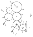
- the Fig. 1 and 2 each show in a schematic representation of a dampening unit 01, preferably a film dampening unit 01, with a first roller 04 and a second roller 06, wherein the first roller 04 a fountain solution 02, z.
- a fountain solution 03 As water 02 or an alcohol-water mixture 02 from a fountain solution source 03, z. B. from a fountain solution 03, in particular from a fountain solution box 03 or from a with the fountain solution 02 filled tub 03 receives, wherein the first roller 04, the fountain solution 02 at least partially transmits directly to the first roller 04 adjacent arranged second roller 06.
- the first roller 04 is thus preferably designed as a dip roller 04 or as a ductor roller 04.
- the fountain solution source 03 z. B.
- the dampening unit 01 may be designed as a brush dampening unit or as a rotary dampening unit, in which the dampening solution 02 is likewise applied contactlessly to the first roller 04.
- the second roller 06 may be a metering roller 06, a wet transfer roller 06 or a friction roller 06, each preferably with a chromed or coated with a ceramic surface.
- the first roller 04 is the first of a plurality of rollers in a compactor over which the dampening solution 02 is transported from the dampening solution reservoir 03 to that forme cylinder 09 of a printing press operating in offset printing, to which the dampening unit 01 is assigned.
- the in the Fig. 1 and 2 differ in particular in the number of their rollers arranged in the compactor.
- the printing machine is z. B. formed as a commercial printing press.
- Your printing unit has at least one forme cylinder 09 and a transfer cylinder (not shown), these two cylinders roll on each other.
- a commercial press preferably an offset press, is intended to mean a printing press with a forme cylinder 09 in which only one single printing form is arranged on its forme cylinder 09, wherein the printing forme preferably has a plurality of print image positions in the axial direction to the forme cylinder 09 , wherein the print image areas are free of a predetermined format, ie, in particular in the axial direction to the forme cylinder 09 within certain limits may have any width.
- Dampening 01 which use a fountain solution 02, the z. B. to reduce environmental pollution or to reduce its costs preferably no or at least very little alcohol, especially isopropyl alcohol (IPA), is added by well below 5% of the volume of the dampening solution 02 total added substances require during production of the printing press , d. H. in their printing operation, for a good printing result, a very precisely adapted to the respective production speed adjustment of the forme cylinder 09 to be transported amount of dampening solution 02. To make matters worse, that for the printing machine an ever higher production speed can be realized. Today's printing presses achieve a production speed of quite 70,000 to 80,000 revolutions per hour for their printing cylinder.
- IPA isopropyl alcohol
- the production speed of the printing machine corresponds to the surface speed v09 of the forme cylinder 09.
- the dampening unit 01 with the features described below provides for the transport of a sufficient and precisely edible quantity even for such a high production speed to dampening solution 02 safe.
- the amount of dampening solution 02 required on the forme cylinder 09 for a good printing result depends on the emulsifying behavior of the ink used and on the quantity of ink required to produce the printed product.
- the paint and the fountain solution 02 form a mixture, wherein depending on the nature of the color in the color within certain limits variable volumetric proportion of the fountain solution 02 is intermingled.
- the backfilled into the dampening unit 01 color, the fountain solution 02 z. B. in a proportion of between 15% and 25% record. The proportion increases with increasing surface velocity v09 of the forme cylinder 09.
- the proportion of the emulsified by the ink fountain solution 02 is z. B. also set an upper limit that the on a substrate, z.
- the dampening unit 01 with the features described below therefore adapts the amount of dampening solution 02 provided on the forme cylinder 09 for a good printing result, also depending on the nature of the color and its quantitative requirement for the printed product to be produced.
- the first roller 04 and the second roller 06 have separate, ie independently controllable, drive devices 07 ; 08 on.
- Independently controllable drive devices 07; 08 for the first roller 04 and the second roller 06 have the advantage that a surface speed v04 of the first roller 04 generated by the drive device 07 and a surface speed v06 of the second roller 06 generated by the drive device 08 does not rigidly change the amount of dampening solution 02 influencing parameter follows, but that for adjusting the amount to be transported of the fountain solution 02 and the ratio of the surface velocities v04; v06 can be adjusted to each other variable and needs-based, whereby the dosage of the moisturizer 02 to be transported by the dampening unit 01 significantly influenced becomes.
- different settings for the surface speed v04 of the first roller 04 and the surface speed v06 of the second roller 06 and for their relationship to one another may result for the same value for the surface speed v09 of the forme cylinder 09.
- the surface speed v04 of the first roller 04 generated by the drive device 07 and the surface speed v06 of the second roller 06 generated by the drive device 08 are i. d. R. different from each other.
- the surface speed v04 of the first roller 04 is less than the surface speed v06 of the second roller 06.
- the surface speeds v04; v06 are independently adjustable and variably adjustable.
- the surface speed v06 of the second roller 06 z.
- the surface speed v04 of the first roller 04 is limited in its height by the requirement that the first roller 04 on its surface the fountain solution 02 from the dampening solution reservoir 03 must reliably record.
- the surface speed v04 of the first roller 04 is preferably set to lower than its upper limit speed, e.g. B. to a value of at most 1.5 m / s.
- the surface velocity v09 of the forme cylinder 09 is z. B. between 12 m / s and 15 m / s.
- the surface speed v06 of the second roller 06 is set greater than the surface speed v04 of the first roller 04, which is generally the case, exists between the first and the second roller 04; 06 a slip because the Surface speed v04 of the first roller 04 remains behind the surface speed v06 of the second roller 06. This is due to the ratio of surface velocities v04; v06 of the two rolls 04; 06 slip formed by the independent drive means 07; 08 for the first roller 04 and the second roller 06 variably adjustable.
- z. B. when booting the surface speed v09 of the forme cylinder 09 z. B. from a setting speed of the printing press on their production speed, the to be transported by the compactor of the dampening unit 01 amount of dampening solution 02 is adjusted.
- the set-up speed of the printing press is z. B. between 1.7 m / s and 3.4 m / s, preferably between 2 m / s and 2.6 m / s, and is thus between 11% and at most 25% of the production speed of the printing press or the surface speed v09 of the forme cylinder 09.
- the surface speed v09 of the forme cylinder 09 is used to reach the production speed, starting from the set-up speed, ie, for example, to the production speed. B. increased fourfold to ninefold.
- a fast-reacting, in the amount of dampening solution 02 to be transported needs customizable dampening unit 01 is required.
- the transporting quantity of dampening solution 02 must be adjusted in each case.
- the current need for fountain solution 02 - as mentioned - depends on the amount of ink required for the printed product to be produced. On this need for adaptation can with a rigid coupling, z. B. a gear coupling between the first roller 04 and the second roller 06 in many applications, especially in printing machines with a large speed stroke, not always be sufficiently responded.
- the drive means 07; 08 of the rollers 04; 06 of the dampening unit 01 in their speed controllable, preferably infinitely controllable, in particular electronically controlled.
- the controller can be remotely controlled z. B. from one of the printing press associated control center.
- the drive means 07; 08 for the first roller 04 and the second roller 06 are preferably as electric motors 07; 08, z. B. as AC or DC motors 07; 08 or as a frequency-controlled three-phase motors 07; 08 trained.
- the drive means 18 of the forme cylinder 09 can be used as an electric motor 18, z. B.
- the drive device 18 of the forme cylinder 09 is in particular of the drive means 07; 08 of the rollers 04; 06 of the dampening unit 01 independently, d. H. in particular, there is no positive connection between the drive devices 07; 08 of the rollers 04; It is not necessary that the drive means 18 of the forme cylinder 09 exclusively drives only the forme cylinder 09, but the drive means 18 transmits the torque generated by it at least to the forme cylinder 09, but possibly also to the latter the form cylinder 09 cooperating transfer cylinder (not shown).
- the control of the drive means 07; 08; 18 can be extended to a control if necessary by adding an actual value detecting feedback and a feedback signal evaluating evaluation, wherein preferably the actual value of a rotational speed of the rollers 04; 06 or the forme cylinder 09 z. B. is detected with a sensor providing an electrical output signal.
- the control or regulation of the drive means 07; 08; 18 is preferably carried out by means of a computing unit (not shown), the z. B. specifies a corridor for favorable settings.
- the first roller 04 and the second roller 06 of the dampening unit 01 form the first rollers in the compactor, which transports the dampening solution 02 to the forme cylinder 09, wherein the surface speed v04 of the first roller 04 and the surface speed v06 of the second roller 06 independently and without rigid Depending on the surface speed v09 of the forme cylinder 09 are adjustable.
- the surface speed v04 of the first roller 04 or the surface speed v06 of the second roller 06 are i. d. R. lower than the surface velocity v09 of the forme cylinder 09th
- the surface speed v09 of the forme cylinder 09 and the surface speed v06 of the second roller 06 are in a first relationship to one another, whereas the surface speeds v06; v09 are in a second operating state of the dampening unit 01 in a second relationship to each other.
- the surface speed v09 of the forme cylinder 09 can have the same value or assume different values from one another.
- the compactor to the forme cylinder 09 can be extended by a third roller 11 or a fourth roller 13, wherein the third roller 11 of the second roller 06 and the fourth roller 13 of the third roller 11 is arranged downstream.
- the third roller 11 is z. B. by a transmission 12, z. B. a gear transmission 12 or a belt drive 12, coupled to the second roller 06.
- the drive of the third roller 11 by friction z.
- the surface speed of the rollers provided in the roller train to the forme cylinder 09 is set such that between the second roller 06 and the third roller 11 or between the third roller 11 and the fourth roller 13 slip exists.
- the slip z. B. 1: 3 wherein the first roller 04 rotates slower than the second roller 06.
- the slip between the second roller 06 and the third roller 11 may be selected to be significantly larger, the third roller 11 rotates much faster than the second roller 06th
- the designated traversing drive 19 from the rotary drive 07; 08 of the rollers 06; 11; 13 decouple and independently controllable design.
- the frequency of the traversing movement is freely selectable.
- the stroke of the traversing movement is z. B. ⁇ 8 mm.
- the traversing drive 19 is z. B. as an electric motor 19, z. B. as a linear motor 19, is formed.
- the fountain solution 02 applying to the forme cylinder 09 roller 11; 13 is driven in particular by friction of the forme cylinder 09.
- the forme cylinder 09 is associated with an inking unit 16 with at least one engageable with the forme cylinder 09 inking roller 17, wherein the inking unit 16 a (not shown) mounted on the surface of the forme cylinder 09 printing form by means of the inking roller 17 colors.
- the fountain solution 02 on the forme cylinder 09 priority-applying roller 06; 11; 13, that is, depending on the design of the roller, the second roller 06, the third roller 11 or the fourth roller 13, then preferably simultaneously to the form cylinder 09 and the inking roller 17 or to an inking roller of cooperating with the forme cylinder 09 inking unit 16 can be adjusted.
- the employment of the fountain solution 02 on the forme cylinder 09 applying roller 06; 11; 13 to the inking roller 17 can thus directly or indirectly via a z. B.
- the first bridge roller 14 upstream second bridge roller 23 may be provided (in Fig. 1 shown in dashed lines), wherein the upstream bridge roller 23 between the first bridge roller 14 and the third roller 11, that is arranged in the roller train before the dampening 02 to the forme cylinder 09 applying fourth roller 13 arranged roller 11 is arranged.
- the first bridge roller 14 is preferably mounted in a frame (not shown) and by at least one actuating means, for.
- a remotely operable working cylinder in particular a pneumatic cylinder (not shown) movable that they either, z. B.
- one of the four operating positions described below can take. In an operating position, it is on the inking roller 17 and not on the fountain solution 02 on the forme cylinder 09 applying roller 06; 11; 13 employed. In another operating position, the bridge roller 14 on which the fountain solution 02 on the forme cylinder 09 applying roller 06; 11; 13 and not employed on the inking roller 17. In another operating position, the bridge roller 14 at the same time on the fountain solution 02 on the forme cylinder 09 applying roller 06; 11; 13 and employed on the inking roller 17, wherein its normal operating position, wherein the bridge roller 14 can be moved in addition, if necessary, in the other remaining operating positions.
- the bridge roller 14 at the same time of the fountain solution 02 on the forme cylinder 09 applying roller 06; 11; 13 and parked by the inking roller 17.
- the bridge roller 14 is then turned on when it with a fountain solution 02 applying to the forme cylinder 09 roller 06; 11; 13 and / or is in operative contact with the inking roller 17 in physical contact or at least for the transport of the ink or dampening solution 02, whereas it is turned off when its surface is the surface of one of said rollers 06; 11; 13; 17 not touched or the surfaces of said rollers 06; 11; 13; 17 are at least not in operative connection for the transport of the paint or dampening solution 02.
- the upstream bridge roller 23 may have a plurality of operating positions by either being engaged on the first bridge roller 14 or on the third roller 11 or by at least one of these rollers 11; 14 is turned off, wherein at least one adjusting means (not shown), z. B. a working cylinder, in particular a pneumatic cylinder, is provided, wherein the adjusting means moves the upstream bridge roller 23 from one to another operating position, wherein the actuation of this actuating means preferably also remotely controlled, in particular from the control room, can take place.
- a working cylinder in particular a pneumatic cylinder
- the flattened strip When touching contact forms between the rollers 04; 06; 11; 13 on its surface, preferably in the axial direction of a flattened strip having a width between 3 mm and 8 mm, preferably between 5 mm and 6 mm, from. Between the dampening solution 02 on the forme cylinder 09 applying roller 06; 11; 13 and the inking roller 17 and the forme cylinder 09, the flattened strip may have a width of 8 mm to 10 mm.
- the width of the strip is to be variable during the printing process, it is advantageous to adjust the setting of the rollers 04; 06; 11; 13; 17 perform with a roller lock, the z. B. remotely controlled, preferably by an operation from the control center, performs a radial stroke.
- the adjustment of the width of the strip is i. d. R. regardless of the surface velocity v09 of the forme cylinder 09th
- the bridge roller 14 is preferably formed iridescent and z. B. from a preferably as a controllable motor 21, z. B. as a linear motor 21, trained traction drive 21 is preferably driven independently of its rotational movement, wherein for their rotational movement another, of the remaining drive means 07; 08; 18 independent drive device 22, z.
- a motor 22, preferably an AC or DC motor 22 or a frequency-controlled three-phase motor 22, in particular an electric, remotely controllable motor 22 may be provided.
- the fountain solution 02 on the forme cylinder 09 applying roller 11; 13 can be adjusted to the bridge roller 14 or turned off by it.
- the fountain solution 02 on the forme cylinder 09 applying roller 11; 13 is parked by the bridge roller 14.
- a working cylinder preferably a pneumatic cylinder, provided, which is the fountain solution 02 on the forme cylinder 09-applying roller 11; 13 with respect to the bridge roller 14 brings in one of the two operating positions or turns off the forme cylinder 09.
- the fountain solution 02 applying to the forme cylinder 09 roller 11; 13 can z. B. be stored in an eccentric bush, in which the fountain solution 02 on the forme cylinder 09 applying roller 11; 13 is moved with the actuating means in its desired operating position.
- the "direct humidification" mode is selected when the the fountain solution 02 on the forme cylinder 09 roller 11; 13 is employed on the forme cylinder 09 and parked by the bridge roller 14.
- the fountain solution 02 carrying on the forme cylinder 09 roller 11; 13 only the fountain solution 02 on the forme cylinder 09 on.
- the mode “indirect humidification” is selected when the fountain solution 02 on the forme cylinder 09 applying roller 11; 13 is employed at the same time on the forme cylinder 09 and on the bridge roller 14.
- "indirect dampening” transports the dampening solution 02 on the forme cylinder 09 applying roller 11; 13 also in not insignificant extent coming from the inking unit 16 color to the forme cylinder 09th
- first roller 04 and the second roller 06 together from the fountain solution 02 on the forme cylinder 09 applying roller 11; 13 are movable.
- the first roller 04 and the second roller 06 may be mounted in a common support, wherein the support z. B. has a pivot about which the support is rotatable, whereby the first roller 04 and the second roller 06 of the fountain solution 02 on the forme cylinder 09 applying roller 11; 13 swing together.
- the surface of the first roller 04 is z. B. of an elastomeric material, preferably of a rubber, in particular of a material having a hardness between 20 and 30 Shore A, preferably about 25 Shore A.
- the surface of the second roller 06 is z. B. from a ceramic or a chromium-containing material, wherein z. B. on a roll core of a metallic material, a coating of a chromium-containing material is applied.
- the surface of the fountain solution 02 on the forme cylinder 09 applying roller 11; 13 is again z. B. of an elastomeric material, preferably of a rubber, in particular of a material having a hardness between 25 and 40 Shore A, preferably about 35 Shore A.
- the surface of the fountain solution 02 on the forme cylinder 09 applying roller 11; 13 is thus preferably harder than the surface of the first roller 04.
- the Surface of the second roller 06 is preferably much harder, z. B. by a factor of ten harder than the surface of the first roller 04 or the surface of the dampening solution 02 on the forme cylinder 09 applying roller 11; 13 trained.
- the surface of the bridge roller 14 is z. B. of a plastic, preferably from Rilsan.
- the surface speeds of the forme cylinder 09 to the roller 02 applying the dampening solution 02 to the forme cylinder 09 to the third roller 11 to the second roller 06 to the first roller 04 behave as 1 to (1 to 0.98) (0.4 to 0, for example). 98) to (0.25 to 0.4) to (0.08 to 0.18), preferably 1 to 0.99 to 0.96 to 0.33 to 0.1.
Abstract
Description
Die Erfindung betrifft ein Feuchtwerk gemäß dem Oberbegriff des Anspruchs 1.The invention relates to a dampening unit according to the preamble of claim 1.
Durch die
Durch die
Durch die
Durch die
Durch die
Durch die
Durch die
Durch die
Durch die
Der Erfindung liegt die Aufgabe zugrunde, ein Feuchtwerk zu schaffen.The invention has for its object to provide a dampening unit.
Die Aufgabe wird erfindungsgemäß durch die Merkmale des Anspruchs 1 gelöst.The object is achieved by the features of claim 1.
Die mit der Erfindung erzielbaren Vorteile bestehen insbesondere darin, dass die Tauchwalze und eine benachbarte Feuchtübertragwalze völlig unabhängig voneinander ansteuerbar sind. Der sich zwischen ihnen ausbildende Schlupf aufgrund einer gewollten Differenz in ihrer Oberflächengeschwindigkeit wird für eine richtige Dosierung eines auf den Walzen aufzutragenden Feuchtmittels bedarfsgerecht angepasst. Die Anpassung des Schlupfes erfolgt insbesondere in Abhängigkeit einer Änderung der Oberflächengeschwindigkeit des Formzylinders.The achievable with the present invention consist in particular in that the fountain roller and an adjacent wet transfer roller can be controlled completely independently. The slip formed between them due to a desired difference in their surface speed is adjusted as needed for a correct dosage of a fountain solution to be applied to the rollers. The adaptation of the slip takes place in particular as a function of a change in the surface speed of the forme cylinder.
Ausführungsbeispiele der Erfindung sind in den Zeichnungen dargestellt und werden im Folgenden näher beschrieben.Embodiments of the invention are illustrated in the drawings and will be described in more detail below.
Es zeigen
- Fig. 1
- ein Feuchtwerk mit vier Walzen im Walzenzug zum Formzylinder;
- Fig. 2
- ein Feuchtwerk mit drei Walzen im Walzenzug zum Formzylinder.
- Fig. 1
- a dampening unit with four rolls in the compactor to form cylinder;
- Fig. 2
- a dampening unit with three rollers in the compactor to form cylinder.
Die
Die Druckmaschine ist z. B. als eine Akzidenzdruckmaschine ausgebildet. Ihr Druckwerk weist mindestens einen Formzylinder 09 und einen Übertragungszylinder (nicht dargestellt) auf, wobei diese beiden Zylinder aufeinander abrollen. Unter einer Akzidenzdruckmaschine, vorzugsweise einer im Offsetdruckverfahren arbeitenden Akzidenzdruckmaschine, soll eine Druckmaschine mit einem Formzylinder 09 verstanden werden, bei der auf ihrem Formzylinder 09 in dessen axialer Richtung nur eine einzige Druckform angeordnet ist, wobei die Druckform in zum Formzylinder 09 axialer Richtung vorzugsweise mehrere Druckbildstellen aufweist, wobei die Druckbildstellen frei von einem vorgegebenen Format sind, d. h. insbesondere in zum Formzylinder 09 axialer Richtung innerhalb bestimmter Grenzen eine beliebige Breite aufweisen können.The printing machine is z. B. formed as a commercial printing press. Your printing unit has at least one
Feuchtwerke 01, die ein Feuchtmittel 02 verwenden, dem z. B. zur Verringerung einer Umweltbelastung oder zur Reduzierung seiner Kosten vorzugsweise gar kein oder zumindest nur sehr wenig Alkohol, insbesondere Isopropylalkohol (IPA), von deutlich unter 5 % vom Volumen der dem Feuchtmittel 02 insgesamt zugesetzten Stoffe zugesetzt ist, erfordern während der Produktion der Druckmaschine, d. h. in ihrem Druckbetrieb, für ein gutes Druckergebnis eine sehr präzise an die jeweilige Produktionsgeschwindigkeit angepasste Einstellung der zum Formzylinder 09 zu transportierenden Menge an Feuchtmittel 02. Erschwerend kommt hinzu, dass für die Druckmaschine eine immer höhere Produktionsgeschwindigkeit zu realisieren ist. Heutige Druckmaschinen erreichen für ihre Druckwerkszylinder eine Produktionsgeschwindigkeit von durchaus 70.000 bis 80.000 Umdrehungen pro Stunde. Wenn die Durchmesser der miteinander in Wirkverbindung stehenden Übertragungszylinder und Formzylinder 09 identisch sind, entspricht die Produktionsgeschwindigkeit der Druckmaschine der Oberflächengeschwindigkeit v09 des Formzylinders 09. Das Feuchtwerk 01 mit den nachfolgend beschriebenen Merkmalen stellt auch für eine derart hohe Produktionsgeschwindigkeit den Transport einer ausreichenden und genau zumessbaren Menge an Feuchtmittel 02 sicher.
Des Weiteren ist die am Formzylinder 09 für ein gutes Druckergebnis benötigte Menge des Feuchtmittels 02 vom Emulgierverhalten der verwendeten Farbe und von der zur Herstellung des Druckerzeugnisses erforderlichen Farbmenge abhängig. Die Farbe und das Feuchtmittel 02 bilden ein Gemenge, wobei je nach der Beschaffenheit der Farbe in der Farbe ein innerhalb bestimmter Grenzen variabler volumetrischer Mengenanteil des Feuchtmittels 02 vermengbar ist. Die ins Feuchtwerk 01 rückgespaltene Farbe kann das Feuchtmittel 02 z. B. in einem Mengeanteil zwischen 15 % und 25 % aufnehmen. Der Mengenanteil nimmt bei größer werdender Oberflächengeschwindigkeit v09 des Formzylinders 09 zu. Dem Mengenanteil des von der Farbe emulgierten Feuchtmittels 02 ist jedoch z. B. auch dadurch ein oberer Schrankenwert gesetzt, dass die auf einen Bedruckstoff, z. B. einer Papierbahn, aufgedruckte Farbe während des Durchlaufs des Bedruckstoffes durch ein dem Druckwerk nachgeordnetes Trocknungsaggregat, z. B. einem Heatset-Trockner, noch sicher trocknen muss. Infolge der angestrebten hohen Produktionsgeschwindigkeit von 12 m/s oder mehr ist die Verweilzeit des Bedruckstoffes im Trocknungsaggregat sehr kurz.Furthermore, the amount of
Je mehr farbige Druckbildstellen ein Druckerzeugnis aufweist, desto mehr Farbe wird am Formzylinder 09 benötigt. Folglich muss in einem solchen Fall zur Einstellung eines für den Druck erforderlichen Gleichgewichts von Farbe und Feuchtmittel 02 auch eine größere Menge des Feuchtmittels 02 am Formzylinder 09 bereitgestellt werden, wenn mit der Druckmaschine ein farbintensiveres Druckerzeugnis produziert wird. Das Feuchtwerk 01 mit den nachfolgend beschriebenen Merkmalen passt die am Formzylinder 09 bereitgestellte Menge des Feuchtmittels 02 für ein gutes Druckergebnis daher auch in Abhängigkeit von der Beschaffenheit der Farbe und ihrem mengenmäßigen Bedarf für das herzustellende Druckerzeugnis an.The more colored print image areas a printed product has, the more color is required on the
Um in Abhängigkeit von der Produktionsgeschwindigkeit der Druckmaschine und des einzustellenden Gleichgewichts von Farbe und Feuchtmittel 02 eine bedarfsgerechte Anpassung der am Formzylinder 09 bereitgestellten Menge des Feuchtmittels 02 zu ermöglichen, weisen die erste Walze 04 und die zweite Walze 06 separate, d. h. voneinander unabhängig steuerbare Antriebseinrichtungen 07; 08 auf. Voneinander unabhängig steuerbare Antriebseinrichtungen 07; 08 für die erste Walze 04 und die zweite Walze 06 haben den Vorteil, dass eine von der Antriebseinrichtung 07 erzeugte Oberflächengeschwindigkeit v04 der ersten Walze 04 und eine von der Antriebseinrichtung 08 erzeugte Oberflächengeschwindigkeit v06 der zweiten Walze 06 nicht starr einer Änderung eines die Menge des Feuchtmittels 02 beeinflussenden Parameters folgt, sondern dass zur Anpassung der zu transportierenden Menge des Feuchtmittels 02 auch das Verhältnis der Oberflächengeschwindigkeiten v04; v06 zueinander variabel und bedarfsgerecht eingestellt werden kann, womit die Dosierung des durch das Feuchtwerk 01 zu transportierenden Feuchtmittels 02 erheblich beeinflusst wird. In Abhängigkeit vom aktuell vorliegenden Druckprozess können sich für denselben Wert für die Oberflächengeschwindigkeit v09 des Formzylinders 09 unterschiedliche Einstellungen für die Oberflächengeschwindigkeit v04 der ersten Walze 04 und die Oberflächengeschwindigkeit v06 der zweiten Walze 06 sowie für ihr Verhältnis zueinander ergeben.In order to enable a needs-based adjustment of the amount of
Die von der Antriebseinrichtung 07 erzeugte Oberflächengeschwindigkeit v04 der ersten Walze 04 und die von der Antriebseinrichtung 08 erzeugte Oberflächengeschwindigkeit v06 der zweiten Walze 06 sind i. d. R. voneinander verschieden. Vorzugsweise ist die Oberflächengeschwindigkeit v04 der ersten Walze 04 geringer als die Oberflächengeschwindigkeit v06 der zweiten Walze 06. Die Oberflächengeschwindigkeiten v04; v06 sind unabhängig voneinander und variabel einstellbar. In einer bevorzugten Ausführung beträgt die Oberflächengeschwindigkeit v06 der zweiten Walze 06 z. B. zwischen dem Doppelten bis Viereinhalbfachen, insbesondere etwa das Dreifache der Oberflächengeschwindigkeit v04 der ersten Walze 04. Die Oberflächengeschwindigkeit v04 der ersten Walze 04 ist in ihrer Höhe durch die Anforderung begrenzt, dass die erste Walze 04 auf ihrer Oberfläche das Feuchtmittel 02 aus dem Feuchtmittelreservoir 03 zuverlässig aufnehmen muss. Erfahrungsgemäß ist ab einer Oberflächengeschwindigkeit v04 der ersten Walze 04 von mehr als 2 m/s eine ausreichende Aufnahme von Feuchtmittel 02 nicht mehr sichergestellt, da dann das Feuchtmittel 02 in erheblichen Maße von der Oberfläche der ersten Walze 04 fortgeschleudert wird. Daher wird die Oberflächengeschwindigkeit v04 der ersten Walze 04 vorzugsweise auf geringere Werte als ihre obere Grenzgeschwindigkeit eingestellt, z. B. auf einen Wert von höchstens 1,5 m/s. Demgegenüber liegt die Oberflächengeschwindigkeit v09 des Formzylinders 09 z. B. zwischen 12 m/s und 15 m/s.The surface speed v04 of the
Wenn die Oberflächengeschwindigkeit v06 der zweiten Walze 06 größer als die Oberflächengeschwindigkeit v04 der ersten Walze 04 eingestellt ist, was i. d. R. der Fall ist, besteht zwischen der ersten und der zweiten Walze 04; 06 ein Schlupf, weil die Oberflächengeschwindigkeit v04 der ersten Walze 04 hinter der Oberflächengeschwindigkeit v06 der zweiten Walze 06 zurückbleibt. Dieser durch das Verhältnis der Oberflächengeschwindigkeiten v04; v06 der beiden Walzen 04; 06 gebildete Schlupf ist durch die voneinander unabhängigen Antriebseinrichtungen 07; 08 für die erste Walze 04 und die zweite Walze 06 variabel einstellbar.If the surface speed v06 of the
In Abhängigkeit einer Veränderung der Oberflächengeschwindigkeit v09 des von einer weiteren Antriebseinrichtung 18 angetriebenen Formzylinders 09, z. B. beim Hochfahren der Oberflächengeschwindigkeit v09 des Formzylinders 09 z. B. von einer Einrichtegeschwindigkeit der Druckmaschine auf ihre Produktionsgeschwindigkeit, ist die vom Walzenzug des Feuchtwerks 01 zu transportierende Menge des Feuchtmittels 02 anzupassen. Die Einrichtegeschwindigkeit der Druckmaschine liegt z. B. zwischen 1,7 m/s und 3,4 m/s, vorzugsweise zwischen 2 m/s und 2,6 m/s, und beträgt damit zwischen 11 % und höchstens 25 % der Produktionsgeschwindigkeit der Druckmaschine bzw. der Oberflächengeschwindigkeit v09 des Formzylinders 09. Die Oberflächengeschwindigkeit v09 des Formzylinders 09 wird zum Erreichen der Produktionsgeschwindigkeit ausgehend von der Einrichtegeschwindigkeit also z. B. um das Vierfache bis zum Neunfachen erhöht. Für diesen großen Geschwindigkeitshub wird ein schnell reagierendes, in der zu transportierenden Menge des Feuchtmittels 02 bedarfsgerecht anpassbares Feuchtwerk 01 benötigt. Gleichfalls ist auch beim Anfahren der Druckmaschine aus ihrem Stillstand oder bei einer Reduzierung der Produktionsgeschwindigkeit die transportierende Menge des Feuchtmittels 02 jeweils anzupassen. Überdies ist der aktuelle Bedarf an Feuchtmittel 02 - wie erwähnt - von der für das herzustellende Druckerzeugnis erforderlichen Farbmenge abhängig. Auf dieses Anpassungsbedürfnis kann mit einer starren Kopplung, z. B. einer Getriebekopplung zwischen der ersten Walze 04 und der zweiten Walze 06 in vielen Anwendungsfällen, insbesondere bei Druckmaschinen mit einem großen Geschwindigkeitshub, nicht immer in ausreichendem Maße reagiert werden.Depending on a change in the surface velocity v09 of the driven by a further drive means 18
Zur Bewerkstelligung der erforderlichen Anpassung sind die Antriebseinrichtungen 07; 08 der Walzen 04; 06 des Feuchtwerks 01 in ihrer Drehzahl steuerbar, vorzugsweise stufenlos steuerbar, insbesondere elektronisch steuerbar. Die Steuerung kann ferngesteuert z. B. von einem der Druckmaschine zugeordneten Leitstand aus erfolgen. Die Antriebseinrichtungen 07; 08 für die erste Walze 04 und die zweite Walze 06 sind vorzugsweise als elektrische Motore 07; 08, z. B. als AC- oder DC-Motore 07; 08 oder als frequenzgesteuerte Drehstrommotore 07; 08 ausgebildet. Auch die Antriebseinrichtung 18 des Formzylinders 09 kann als ein elektrischer Motor 18, z. B. als ein AC- oder DC-Motor 18 oder als ein frequenzgesteuerter Drehstrommotor 18 ausgebildet sein und gleichfalls wie die Antriebseinrichtungen 07; 08 der Walzen 04; 06 des Feuchtwerks 01 steuerbar sein. Die Antriebseinrichtung 18 des Formzylinders 09 ist insbesondere von den Antriebseinrichtungen 07; 08 der Walzen 04; 06 des Feuchtwerks 01 unabhängig, d. h. es besteht insbesondere kein Formschluss zwischen den Antriebseinrichtungen 07; 08 der Walzen 04; 06 und der Antriebseinrichtung 18 des Formzylinders 09. Es ist nicht erforderlich, dass die Antriebseinrichtung 18 des Formzylinders 09 ausschließlich nur den Formzylinder 09 antreibt, jedoch überträgt die Antriebseinrichtung 18 das von ihr erzeugte Drehmoment zumindest auf den Formzylinder 09, gegebenenfalls aber auch auf den mit dem Formzylinder 09 zusammenwirkenden Übertragungszylinder (nicht dargestellt).To accomplish the required adjustment, the drive means 07; 08 of the
Die Steuerung der Antriebseinrichtungen 07; 08; 18 kann bei Bedarf durch Hinzufügung einer einen Istwert erfassenden Rückkopplung und einer ein rückgekoppeltes Signal auswertenden Auswerteeinrichtung zu einer Regelung erweitert werden, wobei vorzugsweise der Istwert einer Drehzahl der Walzen 04; 06 oder des Formzylinders 09 z. B. mit einem ein elektrisches Ausgangssignal bereitstellenden Sensor erfasst wird. Die Steuerung bzw. Regelung der Antriebseinrichtungen 07; 08; 18 erfolgt vorzugsweise mithilfe einer Recheneinheit (nicht dargestellt), die z. B. einen Korridor für günstige Einstellwerte vorgibt.The control of the drive means 07; 08; 18 can be extended to a control if necessary by adding an actual value detecting feedback and a feedback signal evaluating evaluation, wherein preferably the actual value of a rotational speed of the
Die erste Walze 04 und die zweite Walze 06 des Feuchtwerks 01 bilden die ersten Walzen in dem Walzenzug, der das Feuchtmittel 02 zum Formzylinder 09 transportiert, wobei die Oberflächengeschwindigkeit v04 der ersten Walze 04 und die Oberflächengeschwindigkeit v06 der zweiten Walze 06 unabhängig voneinander und ohne starre Abhängigkeit von der Oberflächengeschwindigkeit v09 des Formzylinders 09 einstellbar sind. Die Oberflächengeschwindigkeit v04 der ersten Walze 04 oder die Oberflächengeschwindigkeit v06 der zweiten Walze 06 sind i. d. R. geringer als die Oberflächengeschwindigkeit v09 des Formzylinders 09.The
Es kann vorgesehen sein, dass in einem ersten Betriebszustand des Feuchtwerks 01 die Oberflächengeschwindigkeit v09 des Formzylinders 09 und die Oberflächengeschwindigkeit v06 der zweiten Walze 06 in einem ersten Verhältnis zueinander stehen, wohingegen die Oberflächengeschwindigkeiten v06; v09 in einem zweiten Betriebszustand des Feuchtwerks 01 in einem zweiten Verhältnis zueinander stehen. Während beider Betriebszustände des Feuchtwerks 01 kann die Oberflächengeschwindigkeit v09 des Formzylinders 09 den gleichen Wert aufweisen oder voneinander verschiedene Werte annehmen.It can be provided that, in a first operating state of the dampening
Der Walzenzug zum Formzylinder 09 kann um eine dritte Walze 11 oder auch um eine vierte Walze 13 erweitert werden, wobei die dritte Walze 11 der zweiten Walze 06 und die vierte Walze 13 der dritten Walze 11 nachgeordnet ist. Die dritte Walze 11 ist z. B. durch ein Getriebe 12, z. B. ein Zahnradgetriebe 12 oder einen Riementrieb 12, mit der zweiten Walze 06 gekoppelt. Alternativ erfolgt der Antrieb der dritten Walze 11 durch Friktion z. B. an der zweiten Walze 06 oder durch Friktion am Formzylinder 09. Die Oberflächengeschwindigkeit der im Walzenzug zum Formzylinder 09 vorgesehenen Walzen ist jeweils derart eingestellt, dass zwischen der zweiten Walze 06 und der dritten Walze 11 oder zwischen der dritten Walze 11 und der vierten Walze 13 Schlupf besteht. Zwischen der ersten Walze 04 und der zweiten Walze 06 kann der Schlupf z. B. 1:3 betragen, wobei die erste Walze 04 langsamer dreht als die zweite Walze 06. Der Schlupf zwischen der zweiten Walze 06 und der dritten Walze 11 kann bedeutend größer gewählt sein, wobei die dritte Walze 11 sehr viel schneller dreht als die zweite Walze 06.The compactor to the
Zur besseren Verteilung des Feuchtmittels 02 auf der Oberfläche der im Walzenzug angeordneten Walzen 06; 11; 13 und zur Verhinderung von Schablonieren ist zumindest eine dieser Walzen 06; 11; 13, die der ersten Walze 04 im Walzenzug nachfolgen, changierend ausgeführt. Es ist erfindungsgemäß, den dafür vorgesehenen Changierantrieb 19 vom rotatorischen Antrieb 07; 08 der Walzen 06; 11; 13 zu entkoppeln und voneinander unabhängig steuerbar auszugestalten. Insbesondere ist die Frequenz der Changierbewegung frei wählbar. Der Hub der Changierbewegung beträgt z. B. ±8 mm. Es kann jedoch auch ein variabel einstellbarer Hub der Changierbewegung z. B. zwischen 0 mm und 16 mm vorgesehen sein. Der Changierantrieb 19 ist z. B. als ein elektrischer Motor 19, z. B. als ein Linearmotor 19, ausgebildet. Die das Feuchtmittel 02 auf den Formzylinder 09 auftragende Walze 11; 13 wird insbesondere über Friktion vom Formzylinder 09 angetrieben.For better distribution of the
Dem Formzylinder 09 ist ein Farbwerk 16 mit mindestens einer an den Formzylinder 09 anstellbaren Farbauftragswalze 17 zugeordnet, wobei das Farbwerk 16 eine auf der Oberfläche des Formzylinders 09 montierte Druckform (nicht dargestellt) mittels der Farbauftragswalze 17 einfärbt. Die das Feuchtmittel 02 auf den Formzylinder 09 vorrangig auftragende Walze 06; 11; 13, d. h. je nach Ausbildung des Walzenzugs die zweite Walze 06, die dritte Walze 11 oder die vierte Walze 13, ist dann vorzugsweise gleichzeitig an den Formzylinder 09 und an die Farbauftragswalze 17 oder an eine Farbreiberwalze des mit dem Formzylinder 09 zusammenwirkenden Farbwerks 16 anstellbar. Die Anstellung der das Feuchtmittel 02 auf den Formzylinder 09 auftragenden Walze 06; 11; 13 an die Farbauftragswalze 17 kann somit unmittelbar oder mittelbar über eine z. B. auch als Farbreiberwalze 14 ausgebildete Brückenwalze 14 erfolgen. Insbesondere in einem Feuchtwerk 01 mit vier Walzen 04; 06; 11; 13 im Walzenzug kann noch eine weitere, der ersten Brückenwalze 14 vorgelagerte zweite Brückenwalze 23 vorgesehen sein (in
Beim Berührungskontakt bildet sich zwischen den Walzen 04; 06; 11; 13 auf deren Oberfläche vorzugsweise in deren axialer Richtung ein abgeplatteter Streifen mit einer Breite zwischen 3 mm und 8 mm, vorzugsweise zwischen 5 mm und 6 mm, aus. Zwischen der das Feuchtmittel 02 auf den Formzylinder 09 auftragenden Walze 06; 11; 13 bzw. der Farbauftragswalze 17 und dem Formzylinder 09 kann der abgeplattete Streifen eine Breite von 8 mm bis zu 10 mm aufweisen. Der Berührungskontakt zwischen den Walzen 04; 06; 11; 13; 17 bzw. dem Formzylinder 09 wird z. B. manuell mit einer Stellspindel vorzugsweise durch eine Wegänderung eingestellt, wobei die eingestellte Breite des Streifens während des Druckprozesses unverändert bleibt. Wenn die Breite des Streifens während des Druckprozesses veränderbar sein soll, ist es vorteilhaft, die Einstellung der Walzen 04; 06; 11; 13; 17 mit einem Walzenschloss auszuführen, das z. B. ferngesteuert, vorzugsweise durch eine Betätigung vom Leitstand aus, einen Radialhub ausführt. Die Einstellung der Breite des Streifens erfolgt i. d. R. unabhängig von der Oberflächengeschwindigkeit v09 des Formzylinders 09.When touching contact forms between the
Die Brückenwalze 14 ist vorzugsweise changierend ausgebildet und wird z. B. von einem vorzugsweise als steuerbaren Motor 21, z. B. als Linearmotor 21, ausgebildeten Changierantrieb 21 vorzugsweise unabhängig von ihrer Rotationsbewegung angetrieben, wobei für ihre Rotationsbewegung eine weitere, von den übrigen Antriebseinrichtungen 07; 08; 18 unabhängige Antriebseinrichtung 22, z. B. ein Motor 22, vorzugsweise ein AC-oder DC-Motor 22 oder ein frequenzgesteuerter Drehstrommotor 22, insbesondere ein elektrischer, fernsteuerbarer Motor 22, vorgesehen sein kann.The
Wenn die das Feuchtmittel 02 auf den Formzylinder 09 auftragende Walze 11; 13 über Friktion angetrieben wird, kann diese Walze 11; 13 im Gestell derart gelagert sein, dass ihr ein axialer Hub von z. B. 3 mm bis 4 mm möglich ist, wobei dieser Hub dadurch ausgeführt wird, dass sie von der Changierbewegung der Brückenwalze 14 mitgenommen wird. Zwischen der das Feuchtmittel 02 auf den Formzylinder 09 auftragende Walze 11; 13 und dem Formzylinder 09 besteht vorzugsweise kein oder nur ein minimaler Schlupf von weniger als 2 %, vorzugsweise von weniger als 1 %. In besonderen Anwendungsfällen kann aber auch als Alternative zum Friktionsantrieb für die Rotationsbewegung der das Feuchtmittel 02 auf den Formzylinder 09 auftragenden Walze 11; 13 eine eigene, von den übrigen Antriebseinrichtungen 07; 08; 18; 22 unabhängige Antriebseinrichtung (nicht dargestellt), z. B. ein Motor, vorzugsweise ein AC- oder DC-Motor oder ein frequenzgesteuerter Drehstrommotor vorgesehen sein.When the
Zur Umstellung des Feuchtwerks 01 zwischen der Betriebsart "direktes Feuchten" und der Betriebsart "indirektes Feuchten" kann vorgesehen sein, dass die das Feuchtmittel 02 auf den Formzylinder 09 auftragende Walze 11; 13 an die Brückenwalze 14 anstellbar oder von ihr abstellbar ist. In der
Es kann vorgesehen sein, dass die erste Walze 04 und die zweite Walze 06 gemeinsam von der das Feuchtmittel 02 auf den Formzylinder 09 auftragenden Walze 11; 13 fortbewegbar sind. Dazu können die erste Walze 04 und die zweite Walze 06 in einem gemeinsamen Support gelagert sein, wobei der Support z. B. einen Drehpunkt aufweist, um den der Support drehbar ist, wodurch die erste Walze 04 und die zweite Walze 06 von der das Feuchtmittel 02 auf den Formzylinder 09 auftragenden Walze 11; 13 gemeinsam abschwenken.It can be provided that the
Die Oberfläche der ersten Walze 04 besteht z. B. aus einem Elastomerwerkstoff, vorzugsweise aus einem Gummi, insbesondere aus einem Werkstoff mit einer Härte zwischen 20 und 30 Shore A, vorzugsweise etwa 25 Shore A. Die Oberfläche der zweiten Walze 06 besteht z. B. aus einer Keramik oder aus einem Chrom haltigen Werkstoff, wobei z. B. auf einem Walzenkern aus einem metallischen Werkstoff eine Beschichtung aus einem Chrom haltigen Werkstoff aufgetragen ist. Die Oberfläche der das Feuchtmittel 02 auf den Formzylinder 09 auftragenden Walze 11; 13 besteht wiederum z. B. aus einem Elastomerwerkstoff, vorzugsweise aus einem Gummi, insbesondere aus einem Werkstoff mit einer Härte zwischen 25 und 40 Shore A, vorzugsweise etwa 35 Shore A. Die Oberfläche der das Feuchtmittel 02 auf den Formzylinder 09 auftragenden Walze 11; 13 ist somit vorzugsweise härter ausgebildet als die Oberfläche der ersten Walze 04. Die Oberfläche der zweiten Walze 06 ist vorzugsweise sehr viel härter, z. B. um den Faktor zehn härter als die Oberfläche der ersten Walze 04 oder die Oberfläche der das Feuchtmittel 02 auf den Formzylinder 09 auftragenden Walze 11; 13 ausgebildet. Die Oberfläche der Brückenwalze 14 besteht z. B. aus einem Kunststoff, vorzugsweise aus Rilsan. Die Oberfläche der vorgelagerten Brückenwalze 23 kann hingegen aus einem Elastomerwerkstoff, vorzugsweise aus einem Gummi, bestehen.The surface of the
Die Oberflächengeschwindigkeiten von Formzylinder 09 zu der das Feuchtmittel 02 auf den Formzylinder 09 auftragenden Walze 13 zur dritten Walze 11 zur zweiten Walze 06 zur ersten Walze 04 verhalten sich beispielsweise wie 1 zu (1 bis 0,98) zu (0,4 bis 0,98) zu (0,25 bis 0,4) zu (0,08 bis 0,18), vorzugsweise 1 zu 0,99 zu 0,96 zu 0,33 zu 0,1. Bei Verwendung von nur drei Walzen im Walzenzug zwischen dem Formzylinder 09 und dem Feuchtmittelreservoir 03 entfällt das für die dritte Walze 11 vorstehend separat genannte Schlupfverhältnis, weil die dritte Walze 11 bereits die das Feuchtmittel 02 auf den Formzylinder 09 auftragenden Walze ist.The surface speeds of the
Bezugszeichenliste
- 01
- Feuchtwerk, Filmfeuchtwerk
- 02
- Feuchtmittel, Wasser, Alkohol-Wasser-Gemisch
- 03
- Feuchtmittelquelle, Feuchtmittelreservoir, Feuchtmittelkasten, Wanne, Sprühbalken, Sprühdüse
- 04
- Walze, erste; Tauchwalze, Duktorwalze
- 05
- -
- 06
- Walze, zweite; Dosierwalze, Feuchtübertragungswalze, Reibwalze
- 07
- Antriebseinrichtung, Motor, AC- oder DC-Motor, Drehstrommotor
- 08
- Antriebseinrichtung, Motor, AC- oder DC-Motor, Drehstrommotor
- 09
- Formzylinder
- 10
- -
- 11
- Walze, dritte
- 12
- Getriebe, Zahnradgetriebe, Riementrieb
- 13
- Walze, vierte
- 14
- Brückenwalze; Farbreiberwalze
- 15
- -
- 16
- Farbwerk
- 17
- Farbauftragswalze
- 18
- Antriebseinrichtung; Motor, Drehstrommotor
- 19
- Changierantrieb; Motor; Linearmotor
- 20
- -
- 21
- Changierantrieb; Motor; Linearmotor
- 22
- Antriebseinrichtung; Motor, AC- oder DC-Motor, Drehstrommotor
- 23
- vorgelagerte Brückenwalze
- v04
- Oberflächengeschwindigkeit (04)
- v06
- Oberflächengeschwindigkeit (06)
- v09
- Oberflächengeschwindigkeit (09)
- 01
- Dampening unit, film dampening unit
- 02
- Dampening solution, water, alcohol-water mixture
- 03
- Dampening agent source, fountain solution reservoir, fountain solution box, tray, spray bar, spray nozzle
- 04
- Roller, first; Dipping roller, ductor roller
- 05
- -
- 06
- Roller, second; Dosing roller, wet transfer roller, rubbing roller
- 07
- Drive device, motor, AC or DC motor, three-phase motor
- 08
- Drive device, motor, AC or DC motor, three-phase motor
- 09
- form cylinder
- 10
- -
- 11
- Roller, third
- 12
- Transmission, gear transmission, belt drive
- 13
- Roller, fourth
- 14
- Bridge roller; Ink distributor roller
- 15
- -
- 16
- inking
- 17
- Inking roller
- 18
- Drive means; Motor, three-phase motor
- 19
- Traversing drive; Engine; linear motor
- 20
- -
- 21
- Traversing drive; Engine; linear motor
- 22
- Drive means; Motor, AC or DC motor, three-phase motor
- 23
- upstream bridge roller
- v04
- Surface speed (04)
- v06
- Surface speed (06)
- v09
- Surface speed (09)
Claims (8)
- Dampening system (01) having a first roll (04) taking up a moistening agent (02) from a moistening agent source (03) and a second roll (06), the first roll (04) transferring the moistening agent (02) to the second roll (06), the first roll (04) and the second roll (06) having separate drive devices (07; 08) for their respective rotational movement, the first roll (04) and the second roll (06) belonging to a drum roller, which transports the moistening agent (02) to a forme cylinder (09) of a printing press driven by a further drive device (18), at least one third roll (11) being provided downstream of the second roll (06) in the drum roller of the forme cylinder (09), which applies the moistening agent (02) to the forme cylinder (09), the second roll (06) oscillating, characterised in that for the oscillating movement of the second roll (06) an oscillating drive (19) independent of its rotational movement is provided, and in that a bridge roller (14) in contact with the third roll (11) and with a colouration roll (17) in contact with the forme cylinder (09) is provided, the bridging roll (14) oscillating and having an oscillating drive (21) independent of its rotational movement.
- Dampening system (01) according to Claim 1, characterised in that a fourth roll (13) is provided in the drum roller between the third roll (11) and the forme cylinder (09), the fourth roll (13) applying the moistening agent (02) to the forme cylinder (09) instead of the third roll (11).
- Moistening system (01) according to Claim 1, characterised in that the third roll (11) downstream of the second roll (06) is coupled to the second roll (06) by a drive (12).
- Dampening system (01) according to Claim 1, characterised in that the bridging roll (14) is in contact in one operating position either with the colouration roll (17) and not with a roll (06; 11; 13) applying the moistening agent (02) to the forme cylinder (09) or in another operating position with a roll (06; 11; 13) applying the moistening agent (02) to the forme cylinder (09) and not with the colouration roll (17).
- Dampening system (01) according to Claim 1, characterised in that the bridging roll (14) in a further operating position is simultaneously in contact neither with the colouration roll (17) nor with a roll (06; 11; 13) applying the moistening agent (02) to the forme cylinder (09).
- Dampening system (01) according to Claim 1, characterised in that the bridging roll (14; 23) having at least one control means is movable optionally to different operating positions, the control means being actuatable by a control centre.
- Dampening system (01) according to Claim 1, characterised in that the roll (11; 13) applying the moistening agent (02) to the forme cylinder (09) is either in contact with the forme cylinder (09) in one operating position and not in contact with the bridging roll (14), or in another operating position the roll (11; 13) applying the moistening agent (02) to the forme cylinder (09) is simultaneously in contact with the forme cylinder (09) and the bridging roll (14).
- Dampening system (01) according to Claim 1, characterised in that the oscillating movement of the bridging roll (14) is freely selectable in its frequency.
Applications Claiming Priority (2)
| Application Number | Priority Date | Filing Date | Title |
|---|---|---|---|
| DE10258326A DE10258326B4 (en) | 2002-12-13 | 2002-12-13 | Method for controlling a first roller and a second roller receiving a dampening solution from a fountain solution reservoir |
| EP03788864A EP1569797B1 (en) | 2002-12-13 | 2003-12-09 | Methods for controlling rolls, which take up a damping agent |
Related Parent Applications (2)
| Application Number | Title | Priority Date | Filing Date |
|---|---|---|---|
| EP03788864A Division EP1569797B1 (en) | 2002-12-13 | 2003-12-09 | Methods for controlling rolls, which take up a damping agent |
| EP03788864.1 Division | 2003-12-09 |
Publications (3)
| Publication Number | Publication Date |
|---|---|
| EP2072251A2 EP2072251A2 (en) | 2009-06-24 |
| EP2072251A3 EP2072251A3 (en) | 2010-05-12 |
| EP2072251B1 true EP2072251B1 (en) | 2012-08-01 |
Family
ID=32518939
Family Applications (3)
| Application Number | Title | Priority Date | Filing Date |
|---|---|---|---|
| EP05104000A Withdrawn EP1582348A3 (en) | 2002-12-13 | 2003-12-09 | Methods for controlling both a first roll, which takes up a damping agent from a damping agent source, as well as a second roll, and damping systems |
| EP03788864A Expired - Lifetime EP1569797B1 (en) | 2002-12-13 | 2003-12-09 | Methods for controlling rolls, which take up a damping agent |
| EP09153642A Expired - Lifetime EP2072251B1 (en) | 2002-12-13 | 2003-12-09 | Dampening system |
Family Applications Before (2)
| Application Number | Title | Priority Date | Filing Date |
|---|---|---|---|
| EP05104000A Withdrawn EP1582348A3 (en) | 2002-12-13 | 2003-12-09 | Methods for controlling both a first roll, which takes up a damping agent from a damping agent source, as well as a second roll, and damping systems |
| EP03788864A Expired - Lifetime EP1569797B1 (en) | 2002-12-13 | 2003-12-09 | Methods for controlling rolls, which take up a damping agent |
Country Status (11)
| Country | Link |
|---|---|
| US (1) | US8256344B2 (en) |
| EP (3) | EP1582348A3 (en) |
| JP (1) | JP2006508839A (en) |
| CN (2) | CN100344448C (en) |
| AT (1) | ATE424998T1 (en) |
| AU (1) | AU2003293280A1 (en) |
| BR (1) | BR0316750A (en) |
| DE (2) | DE10258326B4 (en) |
| ES (1) | ES2320213T3 (en) |
| RU (1) | RU2296676C2 (en) |
| WO (1) | WO2004054804A1 (en) |
Families Citing this family (19)
| Publication number | Priority date | Publication date | Assignee | Title |
|---|---|---|---|---|
| DE102004056277A1 (en) | 2004-02-09 | 2005-09-08 | Koenig & Bauer Ag | Method for distributing a fountain solution to be transported from a first roller to the surface of a forme cylinder of a printing press |
| DE102004022084A1 (en) * | 2004-05-05 | 2005-12-08 | Man Roland Druckmaschinen Ag | Dampening for a printing press |
| JP2006062363A (en) | 2004-08-25 | 2006-03-09 | Heidelberger Druckmas Ag | Printing machine |
| DE102005009681A1 (en) * | 2005-03-03 | 2006-09-07 | Man Roland Druckmaschinen Ag | Dampening unit for an offset printing unit of a printing machine |
| DE102005031957B4 (en) * | 2005-07-08 | 2007-03-22 | Koenig & Bauer Ag | Apparatus for inspecting a substrate with non-uniform reflective surfaces |
| FR2892661B1 (en) * | 2005-11-03 | 2008-02-01 | Goss Int Montataire Sa | METHOD OF ADJUSTING THE INK QUANTITY APPLIED ON A PRODUCT TO BE PRINTED AND CORRESPONDING DEVICE. |
| CN101495315B (en) * | 2006-05-23 | 2011-02-02 | 柯尼格及包尔公开股份有限公司 | Inking unit of a rotary press, comprising a film roller |
| JP5334365B2 (en) † | 2006-10-23 | 2013-11-06 | 株式会社ミヤコシ | Dampening device for offset printing machine |
| DE102008003239B4 (en) * | 2007-02-06 | 2015-12-03 | Heidelberger Druckmaschinen Ag | Method for operating a dampening system of a printing press |
| EP2114681B1 (en) | 2007-02-07 | 2010-12-01 | Koenig & Bauer Aktiengesellschaft | Printing unit of a rotary printing press and a method for washing a dampening unit of a printing unit |
| DE102007006063B4 (en) | 2007-02-07 | 2009-10-01 | Koenig & Bauer Aktiengesellschaft | Printing unit of a rotary printing machine |
| DE102007015402A1 (en) | 2007-03-30 | 2008-10-09 | Koenig & Bauer Aktiengesellschaft | Dampening unit for a printing unit of a printing machine |
| DE102007015401B4 (en) | 2007-03-30 | 2010-09-23 | Koenig & Bauer Aktiengesellschaft | Dampening unit for a printing unit of a printing machine |
| DE102007015404B4 (en) | 2007-03-30 | 2009-01-08 | Koenig & Bauer Aktiengesellschaft | Dampening unit for a printing unit of a printing machine |
| DE102008001860A1 (en) * | 2008-05-19 | 2009-11-26 | Manroland Ag | Printing machine i.e. sheet-fed printing press, operating method, involves adjusting delta value and/or difference value between speeds of form cylinder and damp applicator roller so that maximum allowable torque at roller is decreased |
| CN101643984B (en) * | 2009-09-08 | 2011-08-17 | 王勇 | Soaking device used in fabric wet transfer printing process |
| DE102011010236A1 (en) | 2011-02-03 | 2012-08-09 | Heidelberger Druckmaschinen Ag | Method for controlling dampening order of printing form in offset printing machine, involves setting speed and direction of rotating dampening rollers on surface of printing form based on print image |
| US9327487B2 (en) * | 2012-08-31 | 2016-05-03 | Xerox Corporation | Variable lithographic printing process |
| CN110239202B (en) * | 2019-06-26 | 2023-06-23 | 云南卓印科技有限公司 | Lithographic printing rubber water roller and preparation method thereof |
Family Cites Families (17)
| Publication number | Priority date | Publication date | Assignee | Title |
|---|---|---|---|---|
| US3168037A (en) * | 1960-05-02 | 1965-02-02 | Harold P Dahlgren | Means for dampening lithographic offset printing plates |
| US3986452A (en) | 1960-05-02 | 1976-10-19 | Dahlgren Manufacturing Company, Inc. | Liquid applicator for lithographic systems |
| CH509156A (en) * | 1969-08-09 | 1971-06-30 | Roland Offsetmaschf | Dampening device for lithographic printing machines |
| EP0022191A1 (en) | 1979-07-05 | 1981-01-14 | Automation für grafische Technik A.G. | Printing machine, particularly offset printing machine |
| DE2927127A1 (en) | 1979-07-05 | 1981-01-08 | Grafische Tech Automation | Offset printing press - has moisture application roller gear driven from plate cylinder and bearing against doctor roller |
| DE2932105C2 (en) * | 1979-08-08 | 1982-08-12 | M.A.N.- Roland Druckmaschinen AG, 6050 Offenbach | Inking unit and dampening unit of a rotary offset printing machine with two inking roller lines |
| ATE73048T1 (en) * | 1987-06-25 | 1992-03-15 | Heidelberger Druckmasch Ag | DAMPENING UNIT FOR AN OFFSET PRINTING PRESS. |
| DE3832527A1 (en) | 1987-09-29 | 1989-04-13 | Jpe Kk | Damping system for an offset printing machine |
| JPH01232045A (en) | 1988-03-14 | 1989-09-18 | J P Ii Kk | Damping apparatus of printing press |
| US4895070A (en) | 1988-07-11 | 1990-01-23 | Birow, Incorporated | Liquid transfer assembly and method |
| FR2663588B1 (en) | 1990-06-21 | 1992-10-09 | Marinoni Harris Sa | FILM WETTING SYSTEM FOR ROTARY OFFSET PRESS. |
| JPH0911435A (en) * | 1994-06-08 | 1997-01-14 | Sun Graphic Technol Inc | Operation method for printing machine and wetting device forprinting machine |
| US5909707A (en) * | 1997-07-24 | 1999-06-08 | Heidelberger Druckmaschinen Ag | High-speed printing system having multiple slipping nips |
| US6138563A (en) * | 1997-10-22 | 2000-10-31 | Baldwin-Japan, Ltd. | Dampening water feeding method and apparatus |
| DE29900216U1 (en) * | 1999-01-11 | 1999-04-15 | Fischer Andreas | Dampening unit for a printing press |
| US6314878B1 (en) * | 2000-01-21 | 2001-11-13 | Ryco Graphic Manufacturing, Inc. | Dampening system for offset printing press and method |
| CN1274495C (en) | 2001-11-08 | 2006-09-13 | 柯尼格及包尔公开股份有限公司 | Drive machanism of printing unit |
-
2002
- 2002-12-13 DE DE10258326A patent/DE10258326B4/en not_active Expired - Fee Related
-
2003
- 2003-12-09 JP JP2004559599A patent/JP2006508839A/en active Pending
- 2003-12-09 WO PCT/DE2003/004038 patent/WO2004054804A1/en active Application Filing
- 2003-12-09 ES ES03788864T patent/ES2320213T3/en not_active Expired - Lifetime
- 2003-12-09 AT AT03788864T patent/ATE424998T1/en not_active IP Right Cessation
- 2003-12-09 AU AU2003293280A patent/AU2003293280A1/en not_active Abandoned
- 2003-12-09 DE DE50311291T patent/DE50311291D1/en not_active Expired - Lifetime
- 2003-12-09 RU RU2005121838/12A patent/RU2296676C2/en not_active IP Right Cessation
- 2003-12-09 BR BR0316750-0A patent/BR0316750A/en active Search and Examination
- 2003-12-09 US US10/537,783 patent/US8256344B2/en not_active Expired - Fee Related
- 2003-12-09 EP EP05104000A patent/EP1582348A3/en not_active Withdrawn
- 2003-12-09 EP EP03788864A patent/EP1569797B1/en not_active Expired - Lifetime
- 2003-12-09 CN CNB2003801055656A patent/CN100344448C/en not_active Expired - Fee Related
- 2003-12-09 CN CN200710180750A patent/CN100586710C/en not_active Expired - Fee Related
- 2003-12-09 EP EP09153642A patent/EP2072251B1/en not_active Expired - Lifetime
Also Published As
| Publication number | Publication date |
|---|---|
| EP2072251A3 (en) | 2010-05-12 |
| CN1723124A (en) | 2006-01-18 |
| CN101134388A (en) | 2008-03-05 |
| CN100586710C (en) | 2010-02-03 |
| US8256344B2 (en) | 2012-09-04 |
| RU2296676C2 (en) | 2007-04-10 |
| US20060081139A1 (en) | 2006-04-20 |
| ATE424998T1 (en) | 2009-03-15 |
| DE10258326A1 (en) | 2004-07-15 |
| DE50311291D1 (en) | 2009-04-23 |
| EP1569797B1 (en) | 2009-03-11 |
| EP1582348A3 (en) | 2006-12-27 |
| EP1569797A1 (en) | 2005-09-07 |
| BR0316750A (en) | 2005-10-25 |
| CN100344448C (en) | 2007-10-24 |
| JP2006508839A (en) | 2006-03-16 |
| RU2005121838A (en) | 2006-01-20 |
| EP1582348A2 (en) | 2005-10-05 |
| WO2004054804A1 (en) | 2004-07-01 |
| ES2320213T3 (en) | 2009-05-20 |
| EP2072251A2 (en) | 2009-06-24 |
| AU2003293280A1 (en) | 2004-07-09 |
| DE10258326B4 (en) | 2006-12-14 |
Similar Documents
| Publication | Publication Date | Title |
|---|---|---|
| EP2072251B1 (en) | Dampening system | |
| EP0064270B2 (en) | Inking unit | |
| EP3043994B1 (en) | Printing press for security printing as well as a method for exchanging a printing plate and for a press start-up | |
| DD250897A5 (en) | FILMFEUCHTWERK FOR OFFSET PRINTING MACHINES | |
| DE102013217942B4 (en) | Method and device for setting bodies of revolution of a printing machine | |
| EP2291288B1 (en) | Device in a printing unit of a printing machine | |
| DE3221514A1 (en) | DEVICE ON MULTICOLOR ROTARY PRINTING MACHINES FOR APPLYING LIQUIDS ON A PRINTING CYLINDER | |
| EP1864801B1 (en) | Printing group of a printing machine | |
| DE10143827A1 (en) | Method for controlling the transfer of a quantity of medium between two rollers | |
| EP1644195B1 (en) | Cylinder of an inking or dampening system | |
| DE19800475A1 (en) | Method and device for influencing the color distribution | |
| DE3906647A1 (en) | Short inking unit | |
| DE102017203560B4 (en) | Printing machine | |
| DE4314426A1 (en) | Method for setting the ink quantity in vibrator inking units of printing machines, in particular sheet-fed offset printing machines, and an appropriately designed vibrator inking unit | |
| WO2006100158A2 (en) | Inking systems of a printing press and method for operating an inking system | |
| DE3011031C2 (en) | Sheet-fed rotary proofing offset printing machine | |
| DD223117A1 (en) | SWITCHING DEVICE FOR A COMBINED HUMIDITY AND PAINTING WORK | |
| DE2324684B2 (en) | Inking or dampening system drive for rotary printing machines | |
| EP2114681A1 (en) | Printing unit of a rotary printing press and a method for washing a dampening unit of a printing unit | |
| EP2233291B1 (en) | Printing group and method for operating the same | |
| DE10329427B4 (en) | Method of operating an inking unit | |
| EP1911581A2 (en) | Ink dosage device for an inking system | |
| EP0962317B1 (en) | Control for a ductor-type inking system | |
| DE3003642A1 (en) | OFFSET PRINTING MACHINE | |
| DE102007015405A1 (en) | Printing tower, has two satellite cylinders arranged in middle frame module, and four pairs of plate cylinders and associated transfer cylinders arranged in lateral frame modules that are arranged adjacent to middle frame module |
Legal Events
| Date | Code | Title | Description |
|---|---|---|---|
| PUAI | Public reference made under article 153(3) epc to a published international application that has entered the european phase |
Free format text: ORIGINAL CODE: 0009012 |
|
| AC | Divisional application: reference to earlier application |
Ref document number: 1569797 Country of ref document: EP Kind code of ref document: P |
|
| AK | Designated contracting states |
Kind code of ref document: A2 Designated state(s): AT BE BG CH CY CZ DE DK EE ES FI FR GB GR HU IE IT LI LU MC NL PT RO SE SI SK TR |
|
| PUAL | Search report despatched |
Free format text: ORIGINAL CODE: 0009013 |
|
| AK | Designated contracting states |
Kind code of ref document: A3 Designated state(s): AT BE BG CH CY CZ DE DK EE ES FI FR GB GR HU IE IT LI LU MC NL PT RO SE SI SK TR |
|
| RIC1 | Information provided on ipc code assigned before grant |
Ipc: B41F 7/26 20060101AFI20090514BHEP Ipc: B41F 7/36 20060101ALI20100408BHEP |
|
| 17P | Request for examination filed |
Effective date: 20100511 |
|
| AKX | Designation fees paid |
Designated state(s): AT BE BG CH CY CZ DE DK EE ES FI FR GB GR HU IE IT LI LU MC NL PT RO SE SI SK TR |
|
| GRAP | Despatch of communication of intention to grant a patent |
Free format text: ORIGINAL CODE: EPIDOSNIGR1 |
|
| RIC1 | Information provided on ipc code assigned before grant |
Ipc: B41F 7/36 20060101ALI20120323BHEP Ipc: B41F 7/26 20060101AFI20120323BHEP |
|
| RTI1 | Title (correction) |
Free format text: DAMPENING SYSTEM |
|
| GRAS | Grant fee paid |
Free format text: ORIGINAL CODE: EPIDOSNIGR3 |
|
| GRAA | (expected) grant |
Free format text: ORIGINAL CODE: 0009210 |
|
| AC | Divisional application: reference to earlier application |
Ref document number: 1569797 Country of ref document: EP Kind code of ref document: P |
|
| AK | Designated contracting states |
Kind code of ref document: B1 Designated state(s): AT BE BG CH CY CZ DE DK EE ES FI FR GB GR HU IE IT LI LU MC NL PT RO SE SI SK TR |
|
| REG | Reference to a national code |
Ref country code: GB Ref legal event code: FG4D Free format text: NOT ENGLISH |
|
| REG | Reference to a national code |
Ref country code: AT Ref legal event code: REF Ref document number: 568443 Country of ref document: AT Kind code of ref document: T Effective date: 20120815 Ref country code: CH Ref legal event code: EP |
|
| REG | Reference to a national code |
Ref country code: IE Ref legal event code: FG4D Free format text: LANGUAGE OF EP DOCUMENT: GERMAN |
|
| REG | Reference to a national code |
Ref country code: DE Ref legal event code: R096 Ref document number: 50314447 Country of ref document: DE Effective date: 20120927 |
|
| REG | Reference to a national code |
Ref country code: NL Ref legal event code: VDEP Effective date: 20120801 |
|
| PG25 | Lapsed in a contracting state [announced via postgrant information from national office to epo] |
Ref country code: CY Free format text: LAPSE BECAUSE OF FAILURE TO SUBMIT A TRANSLATION OF THE DESCRIPTION OR TO PAY THE FEE WITHIN THE PRESCRIBED TIME-LIMIT Effective date: 20120801 Ref country code: FI Free format text: LAPSE BECAUSE OF FAILURE TO SUBMIT A TRANSLATION OF THE DESCRIPTION OR TO PAY THE FEE WITHIN THE PRESCRIBED TIME-LIMIT Effective date: 20120801 |
|
| PGFP | Annual fee paid to national office [announced via postgrant information from national office to epo] |
Ref country code: DE Payment date: 20121207 Year of fee payment: 10 |
|
| PG25 | Lapsed in a contracting state [announced via postgrant information from national office to epo] |
Ref country code: SE Free format text: LAPSE BECAUSE OF FAILURE TO SUBMIT A TRANSLATION OF THE DESCRIPTION OR TO PAY THE FEE WITHIN THE PRESCRIBED TIME-LIMIT Effective date: 20120801 Ref country code: GR Free format text: LAPSE BECAUSE OF FAILURE TO SUBMIT A TRANSLATION OF THE DESCRIPTION OR TO PAY THE FEE WITHIN THE PRESCRIBED TIME-LIMIT Effective date: 20121102 Ref country code: SI Free format text: LAPSE BECAUSE OF FAILURE TO SUBMIT A TRANSLATION OF THE DESCRIPTION OR TO PAY THE FEE WITHIN THE PRESCRIBED TIME-LIMIT Effective date: 20120801 Ref country code: PT Free format text: LAPSE BECAUSE OF FAILURE TO SUBMIT A TRANSLATION OF THE DESCRIPTION OR TO PAY THE FEE WITHIN THE PRESCRIBED TIME-LIMIT Effective date: 20121203 |
|
| PGFP | Annual fee paid to national office [announced via postgrant information from national office to epo] |
Ref country code: GB Payment date: 20121227 Year of fee payment: 10 |
|
| PG25 | Lapsed in a contracting state [announced via postgrant information from national office to epo] |
Ref country code: NL Free format text: LAPSE BECAUSE OF FAILURE TO SUBMIT A TRANSLATION OF THE DESCRIPTION OR TO PAY THE FEE WITHIN THE PRESCRIBED TIME-LIMIT Effective date: 20120801 |
|
| PG25 | Lapsed in a contracting state [announced via postgrant information from national office to epo] |
Ref country code: EE Free format text: LAPSE BECAUSE OF FAILURE TO SUBMIT A TRANSLATION OF THE DESCRIPTION OR TO PAY THE FEE WITHIN THE PRESCRIBED TIME-LIMIT Effective date: 20120801 Ref country code: CZ Free format text: LAPSE BECAUSE OF FAILURE TO SUBMIT A TRANSLATION OF THE DESCRIPTION OR TO PAY THE FEE WITHIN THE PRESCRIBED TIME-LIMIT Effective date: 20120801 Ref country code: DK Free format text: LAPSE BECAUSE OF FAILURE TO SUBMIT A TRANSLATION OF THE DESCRIPTION OR TO PAY THE FEE WITHIN THE PRESCRIBED TIME-LIMIT Effective date: 20120801 Ref country code: ES Free format text: LAPSE BECAUSE OF FAILURE TO SUBMIT A TRANSLATION OF THE DESCRIPTION OR TO PAY THE FEE WITHIN THE PRESCRIBED TIME-LIMIT Effective date: 20121112 Ref country code: RO Free format text: LAPSE BECAUSE OF FAILURE TO SUBMIT A TRANSLATION OF THE DESCRIPTION OR TO PAY THE FEE WITHIN THE PRESCRIBED TIME-LIMIT Effective date: 20120801 |
|
| PGFP | Annual fee paid to national office [announced via postgrant information from national office to epo] |
Ref country code: FR Payment date: 20130117 Year of fee payment: 10 |
|
| PG25 | Lapsed in a contracting state [announced via postgrant information from national office to epo] |
Ref country code: SK Free format text: LAPSE BECAUSE OF FAILURE TO SUBMIT A TRANSLATION OF THE DESCRIPTION OR TO PAY THE FEE WITHIN THE PRESCRIBED TIME-LIMIT Effective date: 20120801 Ref country code: IT Free format text: LAPSE BECAUSE OF FAILURE TO SUBMIT A TRANSLATION OF THE DESCRIPTION OR TO PAY THE FEE WITHIN THE PRESCRIBED TIME-LIMIT Effective date: 20120801 |
|
| PLBE | No opposition filed within time limit |
Free format text: ORIGINAL CODE: 0009261 |
|
| STAA | Information on the status of an ep patent application or granted ep patent |
Free format text: STATUS: NO OPPOSITION FILED WITHIN TIME LIMIT |
|
| BERE | Be: lapsed |
Owner name: KOENIG & BAUER A.G. Effective date: 20121231 |
|
| 26N | No opposition filed |
Effective date: 20130503 |
|
| PG25 | Lapsed in a contracting state [announced via postgrant information from national office to epo] |
Ref country code: BG Free format text: LAPSE BECAUSE OF FAILURE TO SUBMIT A TRANSLATION OF THE DESCRIPTION OR TO PAY THE FEE WITHIN THE PRESCRIBED TIME-LIMIT Effective date: 20121101 Ref country code: MC Free format text: LAPSE BECAUSE OF NON-PAYMENT OF DUE FEES Effective date: 20121231 |
|
| REG | Reference to a national code |
Ref country code: CH Ref legal event code: PL |
|
| REG | Reference to a national code |
Ref country code: DE Ref legal event code: R097 Ref document number: 50314447 Country of ref document: DE Effective date: 20130503 |
|
| REG | Reference to a national code |
Ref country code: IE Ref legal event code: MM4A |
|
| PG25 | Lapsed in a contracting state [announced via postgrant information from national office to epo] |
Ref country code: BE Free format text: LAPSE BECAUSE OF NON-PAYMENT OF DUE FEES Effective date: 20121231 |
|
| PG25 | Lapsed in a contracting state [announced via postgrant information from national office to epo] |
Ref country code: IE Free format text: LAPSE BECAUSE OF NON-PAYMENT OF DUE FEES Effective date: 20121209 Ref country code: LI Free format text: LAPSE BECAUSE OF NON-PAYMENT OF DUE FEES Effective date: 20121231 Ref country code: CH Free format text: LAPSE BECAUSE OF NON-PAYMENT OF DUE FEES Effective date: 20121231 |
|
| REG | Reference to a national code |
Ref country code: AT Ref legal event code: MM01 Ref document number: 568443 Country of ref document: AT Kind code of ref document: T Effective date: 20121209 |
|
| PG25 | Lapsed in a contracting state [announced via postgrant information from national office to epo] |
Ref country code: TR Free format text: LAPSE BECAUSE OF FAILURE TO SUBMIT A TRANSLATION OF THE DESCRIPTION OR TO PAY THE FEE WITHIN THE PRESCRIBED TIME-LIMIT Effective date: 20120801 |
|
| PG25 | Lapsed in a contracting state [announced via postgrant information from national office to epo] |
Ref country code: LU Free format text: LAPSE BECAUSE OF NON-PAYMENT OF DUE FEES Effective date: 20121209 Ref country code: AT Free format text: LAPSE BECAUSE OF NON-PAYMENT OF DUE FEES Effective date: 20121209 |
|
| REG | Reference to a national code |
Ref country code: DE Ref legal event code: R119 Ref document number: 50314447 Country of ref document: DE |
|
| PG25 | Lapsed in a contracting state [announced via postgrant information from national office to epo] |
Ref country code: HU Free format text: LAPSE BECAUSE OF FAILURE TO SUBMIT A TRANSLATION OF THE DESCRIPTION OR TO PAY THE FEE WITHIN THE PRESCRIBED TIME-LIMIT Effective date: 20031209 |
|
| GBPC | Gb: european patent ceased through non-payment of renewal fee |
Effective date: 20131209 |
|
| REG | Reference to a national code |
Ref country code: FR Ref legal event code: ST Effective date: 20140829 |
|
| REG | Reference to a national code |
Ref country code: DE Ref legal event code: R119 Ref document number: 50314447 Country of ref document: DE Effective date: 20140701 |
|
| PG25 | Lapsed in a contracting state [announced via postgrant information from national office to epo] |
Ref country code: DE Free format text: LAPSE BECAUSE OF NON-PAYMENT OF DUE FEES Effective date: 20140701 |
|
| PG25 | Lapsed in a contracting state [announced via postgrant information from national office to epo] |
Ref country code: FR Free format text: LAPSE BECAUSE OF NON-PAYMENT OF DUE FEES Effective date: 20131231 Ref country code: GB Free format text: LAPSE BECAUSE OF NON-PAYMENT OF DUE FEES Effective date: 20131209 |