EP2067201B1 - Separator für eine brennstoffzelle und herstellungsverfahren dafür - Google Patents
Separator für eine brennstoffzelle und herstellungsverfahren dafür Download PDFInfo
- Publication number
- EP2067201B1 EP2067201B1 EP07829157.2A EP07829157A EP2067201B1 EP 2067201 B1 EP2067201 B1 EP 2067201B1 EP 07829157 A EP07829157 A EP 07829157A EP 2067201 B1 EP2067201 B1 EP 2067201B1
- Authority
- EP
- European Patent Office
- Prior art keywords
- separator
- resin composition
- fuel cell
- flow path
- electrically conducting
- Prior art date
- Legal status (The legal status is an assumption and is not a legal conclusion. Google has not performed a legal analysis and makes no representation as to the accuracy of the status listed.)
- Not-in-force
Links
Images


Classifications
-
- H—ELECTRICITY
- H01—ELECTRIC ELEMENTS
- H01M—PROCESSES OR MEANS, e.g. BATTERIES, FOR THE DIRECT CONVERSION OF CHEMICAL ENERGY INTO ELECTRICAL ENERGY
- H01M8/00—Fuel cells; Manufacture thereof
- H01M8/02—Details
- H01M8/0202—Collectors; Separators, e.g. bipolar separators; Interconnectors
- H01M8/0204—Non-porous and characterised by the material
- H01M8/0213—Gas-impermeable carbon-containing materials
-
- H—ELECTRICITY
- H01—ELECTRIC ELEMENTS
- H01M—PROCESSES OR MEANS, e.g. BATTERIES, FOR THE DIRECT CONVERSION OF CHEMICAL ENERGY INTO ELECTRICAL ENERGY
- H01M8/00—Fuel cells; Manufacture thereof
- H01M8/02—Details
-
- H—ELECTRICITY
- H01—ELECTRIC ELEMENTS
- H01M—PROCESSES OR MEANS, e.g. BATTERIES, FOR THE DIRECT CONVERSION OF CHEMICAL ENERGY INTO ELECTRICAL ENERGY
- H01M8/00—Fuel cells; Manufacture thereof
- H01M8/02—Details
- H01M8/0202—Collectors; Separators, e.g. bipolar separators; Interconnectors
- H01M8/0204—Non-porous and characterised by the material
- H01M8/0221—Organic resins; Organic polymers
-
- H—ELECTRICITY
- H01—ELECTRIC ELEMENTS
- H01M—PROCESSES OR MEANS, e.g. BATTERIES, FOR THE DIRECT CONVERSION OF CHEMICAL ENERGY INTO ELECTRICAL ENERGY
- H01M8/00—Fuel cells; Manufacture thereof
- H01M8/02—Details
- H01M8/0202—Collectors; Separators, e.g. bipolar separators; Interconnectors
- H01M8/0204—Non-porous and characterised by the material
- H01M8/0223—Composites
- H01M8/0226—Composites in the form of mixtures
-
- H—ELECTRICITY
- H01—ELECTRIC ELEMENTS
- H01M—PROCESSES OR MEANS, e.g. BATTERIES, FOR THE DIRECT CONVERSION OF CHEMICAL ENERGY INTO ELECTRICAL ENERGY
- H01M8/00—Fuel cells; Manufacture thereof
- H01M8/02—Details
- H01M8/0202—Collectors; Separators, e.g. bipolar separators; Interconnectors
- H01M8/0204—Non-porous and characterised by the material
- H01M8/0223—Composites
- H01M8/0228—Composites in the form of layered or coated products
-
- H—ELECTRICITY
- H01—ELECTRIC ELEMENTS
- H01M—PROCESSES OR MEANS, e.g. BATTERIES, FOR THE DIRECT CONVERSION OF CHEMICAL ENERGY INTO ELECTRICAL ENERGY
- H01M8/00—Fuel cells; Manufacture thereof
- H01M8/02—Details
- H01M8/0202—Collectors; Separators, e.g. bipolar separators; Interconnectors
- H01M8/0247—Collectors; Separators, e.g. bipolar separators; Interconnectors characterised by the form
- H01M8/0254—Collectors; Separators, e.g. bipolar separators; Interconnectors characterised by the form corrugated or undulated
-
- H—ELECTRICITY
- H01—ELECTRIC ELEMENTS
- H01M—PROCESSES OR MEANS, e.g. BATTERIES, FOR THE DIRECT CONVERSION OF CHEMICAL ENERGY INTO ELECTRICAL ENERGY
- H01M8/00—Fuel cells; Manufacture thereof
- H01M8/02—Details
- H01M8/0202—Collectors; Separators, e.g. bipolar separators; Interconnectors
- H01M8/0258—Collectors; Separators, e.g. bipolar separators; Interconnectors characterised by the configuration of channels, e.g. by the flow field of the reactant or coolant
- H01M8/026—Collectors; Separators, e.g. bipolar separators; Interconnectors characterised by the configuration of channels, e.g. by the flow field of the reactant or coolant characterised by grooves, e.g. their pitch or depth
-
- H—ELECTRICITY
- H01—ELECTRIC ELEMENTS
- H01M—PROCESSES OR MEANS, e.g. BATTERIES, FOR THE DIRECT CONVERSION OF CHEMICAL ENERGY INTO ELECTRICAL ENERGY
- H01M8/00—Fuel cells; Manufacture thereof
- H01M8/02—Details
- H01M8/0202—Collectors; Separators, e.g. bipolar separators; Interconnectors
- H01M8/0258—Collectors; Separators, e.g. bipolar separators; Interconnectors characterised by the configuration of channels, e.g. by the flow field of the reactant or coolant
- H01M8/0263—Collectors; Separators, e.g. bipolar separators; Interconnectors characterised by the configuration of channels, e.g. by the flow field of the reactant or coolant having meandering or serpentine paths
-
- H—ELECTRICITY
- H01—ELECTRIC ELEMENTS
- H01M—PROCESSES OR MEANS, e.g. BATTERIES, FOR THE DIRECT CONVERSION OF CHEMICAL ENERGY INTO ELECTRICAL ENERGY
- H01M8/00—Fuel cells; Manufacture thereof
- H01M8/24—Grouping of fuel cells, e.g. stacking of fuel cells
- H01M8/2465—Details of groupings of fuel cells
- H01M8/2483—Details of groupings of fuel cells characterised by internal manifolds
-
- B—PERFORMING OPERATIONS; TRANSPORTING
- B82—NANOTECHNOLOGY
- B82Y—SPECIFIC USES OR APPLICATIONS OF NANOSTRUCTURES; MEASUREMENT OR ANALYSIS OF NANOSTRUCTURES; MANUFACTURE OR TREATMENT OF NANOSTRUCTURES
- B82Y30/00—Nanotechnology for materials or surface science, e.g. nanocomposites
-
- H—ELECTRICITY
- H01—ELECTRIC ELEMENTS
- H01M—PROCESSES OR MEANS, e.g. BATTERIES, FOR THE DIRECT CONVERSION OF CHEMICAL ENERGY INTO ELECTRICAL ENERGY
- H01M8/00—Fuel cells; Manufacture thereof
- H01M8/10—Fuel cells with solid electrolytes
- H01M2008/1095—Fuel cells with polymeric electrolytes
-
- Y—GENERAL TAGGING OF NEW TECHNOLOGICAL DEVELOPMENTS; GENERAL TAGGING OF CROSS-SECTIONAL TECHNOLOGIES SPANNING OVER SEVERAL SECTIONS OF THE IPC; TECHNICAL SUBJECTS COVERED BY FORMER USPC CROSS-REFERENCE ART COLLECTIONS [XRACs] AND DIGESTS
- Y02—TECHNOLOGIES OR APPLICATIONS FOR MITIGATION OR ADAPTATION AGAINST CLIMATE CHANGE
- Y02E—REDUCTION OF GREENHOUSE GAS [GHG] EMISSIONS, RELATED TO ENERGY GENERATION, TRANSMISSION OR DISTRIBUTION
- Y02E60/00—Enabling technologies; Technologies with a potential or indirect contribution to GHG emissions mitigation
- Y02E60/30—Hydrogen technology
- Y02E60/50—Fuel cells
-
- Y—GENERAL TAGGING OF NEW TECHNOLOGICAL DEVELOPMENTS; GENERAL TAGGING OF CROSS-SECTIONAL TECHNOLOGIES SPANNING OVER SEVERAL SECTIONS OF THE IPC; TECHNICAL SUBJECTS COVERED BY FORMER USPC CROSS-REFERENCE ART COLLECTIONS [XRACs] AND DIGESTS
- Y02—TECHNOLOGIES OR APPLICATIONS FOR MITIGATION OR ADAPTATION AGAINST CLIMATE CHANGE
- Y02P—CLIMATE CHANGE MITIGATION TECHNOLOGIES IN THE PRODUCTION OR PROCESSING OF GOODS
- Y02P70/00—Climate change mitigation technologies in the production process for final industrial or consumer products
- Y02P70/50—Manufacturing or production processes characterised by the final manufactured product
Definitions
- the present invention relates to a carbon (carbonaceous) resin-molded separator which is lightweight, compact and excellent in electrical conductivity and mechanical properties, and a production method thereof.
- a fuel cell is a clean power generating device which generates electric power by a reverse electrolysis reaction of water using hydrogen and oxygen and only discharges water, which is classified into several species according to the kind of the electrolyte and among these, a solid polymer-type fuel cell operates at a low temperature and is most promising for automobile or electrical appliances.
- Such a fuel cell is fabricated, for example, by stacking single cells each comprising a polymer solid electrolyte, a gas diffusing electrode, a catalyst and a separator, whereby high-output power generation can be achieved.
- the fuel cell having the above-described construction has a separator for dividing single cells.
- a flow path (groove) for supplying a fuel gas (e.g., hydrogen) and an oxidant gas (e.g., oxygen) and for discharging water (water vapor) generated is usually formed on the separator. Therefore, the separator is required to have high gas impermeability enabling complete separation of these gases and high electrical conductivity for decreasing internal resistance. Furthermore, the separator is required to be excellent in heat conductivity, durability, strength and the like.
- the separator for a fuel cell has been studied from both aspects of a metal material and a carbon material.
- the metal material has a large specific gravity, but is advantageous in that a thin separator can be fabricated because of its excellent mechanical properties, and moreover electrical conductivity is high.
- corrosion resistance Studies are being made on the design of a surface treatment or composition that has excellent corrosion resistance.
- examples of the material for the fuel cell separator include a molded article obtained by press-molding an expanded graphite sheet, a molded article obtained by impregnating a carbon sintered body with a resin and curing it, a glass-like carbon obtained by firing a thermosetting resin, and a molded article obtained by mixing a carbon powder and a resin and molding the mixture.
- Patent Document 1 discloses a complicated process of adding a binder material to a carbonaceous powder, mixing these under heating, subjecting the mixture to CIP molding (cold isostatic pressing), firing and graphitization, impregnating the obtained isotropic graphite material with a thermosetting resin and after curing, engraving a groove by cutting.
- Patent Document 2 discloses a technique of impregnating carbon powder- or carbon fiber-containing paper sheets with a thermosetting resin, stacking and press-bonding the paper sheets, and firing the stack
- Patent Document 3 discloses a technique of injection molding a phenol resin in a separator-shaped mold, and firing the molded article.
- Such a material obtained through firing as in these examples exhibits high electrical conductivity and high heat resistance, but has problems that firing takes a long time to make the productivity low or that brittle destruction readily occurs. Furthermore, in the case where cutting is necessary, mass productivity is decreased and cost rises. For these reasons, the material will be difficult to spread in the future.
- Patent Document 4 discloses a technique of coating a separator surface with a metal or carbon having high electrical conductivity
- Patent Document 5 discloses a technique of applying an electrically conducting polymer to the surface of a molded article of an electrically conducting resin composition
- Patent Document 6 discloses a technique of applying an electrically conducting material to the surface or embedding it in the inside in the longitudinal direction.
- Patent Document 7 discloses a technique of cutting the resin-rich layer (a layer rich in resin) on the separator surface to increase the area ratio of carbon powder on the surface
- Patent Document 8 discloses a technique of using rubber for the binder to enhance the adhesion on the contact surface
- Patent Document 9 discloses a technique where a separator having a power generating part composed of a carbon-based material and an outer frame portion composed of an electrically nonconducting polymer material is processed by insert molding
- Patent Document 10 discloses a technique where a separator and a gasket are integrated.
- the separator for a fuel cell is conventionally required to satisfy, particularly, high electrical conductivity, gas impermeability, strong corrosion resistance and low cost. Furthermore, a lightweight and compact separator capable of exerting its high performance in a limited space is demanded.
- the carbon-based separator has a low specific gravity as compared with metal and can advantageously contribute to lightweighting, but when the wall thickness is reduced, cracking readily occurs and the reliability of gas shielding decreases. In this way, a separator as thin as a metal separator is difficult to produce.
- a gasket or a packing is mainly used to prevent the escape of gas but since the number of fabrication steps increases and the process becomes cumbersome, a structure not using such a gasket or packing is demanded.
- the flow path has a shape of symmetry from front to back and has a largely uneven thickness and when the material has a high viscosity, the processability is bad and a density difference is readily produced between thick-wall part and thin-wall part. In this meaning, high flowability is required for molding a separator with excellent surface precision.
- An object of the present invention is to overcome these drawbacks of conventional techniques and provide a lightweight, compact and high-performance fuel cell separator and a production method thereof.
- a thin separator having a corrugated flow path can be molded at a high speed by a processing method of molding a thermoplastic resin composition highly filled with a carbonaceous material into a thin sheet form, heating the sheet to a melted state, and cold-shaping the melt at a high speed; and also found that such a corrugated thin separator is very effective for solving the above-described problems of conventional techniques.
- the present invention has been accomplished based on these findings.
- the present inventors have further proceeded with studies, as a result, it has been found that particularly when the flow path is formed in a corrugated shape with less unevenness in the thickness, the process is only to change the shape almost without flowing the material and application of a high-viscosity material highly filled with a filler is optimal, and also found that since the thin separator of the present invention having the above-described construction is highly filled with a carbonaceous material to ensure very high heat conductivity and enable rapid solidification, high-speed cold shaping by stamp-molding is effective.
- the present inventors have found that when the sheet is formed in a multilayer structure, the contact resistance with the gas diffusing electrode can be reduced.
- the invention provides a separator for a fuel cell according to claim 1 and a method for producing a separator according to claim 11. Further embodiments of the invention are described in the dependent claims.
- the separator for a fuel cell of the present invention is lightweight and assured of low contact resistance and excellent properties as the separator. Also, according to the production method of the present invention, a groove can be formed on both surfaces of a sheet comprising an electrically conducting resin composition by stamp-molding, so that a separator for a fuel cell can be provided at a low cost.
- 1 is a separator for fuel cell
- 2 is a flow path (for reaction gas)
- 3 is a projection
- 4 is a recess
- 5 is an offset of projections of front and back flow paths
- 6 is a carbon paper
- 7 is a supporting plate (gold-plated brass plate)
- 8 is an MEA
- 9 is a frame body part
- 10 is an MEA body
- 11 is a specimen (separator)
- 12 is an MEA (solid polymer membrane + catalyst + carbon paper)
- 13 is an insulating frame body
- 14 is a five-layer structure MEA.
- the separator for a fuel cell of the present invention comprises an electrically conducting resin composition comprising a carbonaceous material (A) and a thermoplastic resin composition (B) and has a corrugated flow path part.
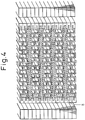
- the corrugated shape indicates a structure having a recess and a projection, where, as shown in Fig. 1 , grooves on the front and back surfaces, each constituting a gas flow path, are alternately arrayed abreast in a plane.
- corrugated separator a metal-made separator is already known.
- a conventional electrically conducting resin composition readily causes breakage due to high brittleness or makes it difficult to reduce the thickness due to low flowability, and a corrugated separator can be hardly produced therefrom.
- an electrically conducting thermoplastic resin composition enabling formation of a sheet in 0.5 mm or less and means for formation into a sheet have been found, and it has become possible to mold a separator at a high speed comparable to the speed in the press molding of a metal by using a stamp-molding method. Only a flow path in a limited shape can be formed by the press molding of a metal, but in the present invention, the sheet is melted, so that a groove or flow path pattern in various shapes can be formed. By virtue of employing the stamp-molding method of the present invention, production of a separator with a small wall thickness and less fluctuation in the thickness at a low cost has been enabled.
- the separator for a fuel cell of the present invention may form a gas seal by using a gasket or a packing as usually done but may be preferably molded integrally with a gasket or a packing. More preferably, a gas seal may be formed by welding without using a gasket or a packing and from 2 to 20 cells may be unitized, whereby a lightweight packingless stack can be fabricated.
- a packing is used in a normal separator for preventing gas leakage, a gas seal can be formed without a packing in the present invention, so that the number of parts can be decreased and the weight can be more reduced.
- the cross-sectional shape is such a shape that the right back of a recess on the first main plane forms a projection on the second main plane and the bottom of a recess on the second main plane comes to a height between the top of a projection and the bottom of a recess on the first main plane, because the separator can be made thin.
- the shape shown in Fig. 13(a) described later may be more preferred than the shape shown in Fig. 13(b) .
- the flow path site where the back surface of a recess on the first main plane forms a projection on the second main plane and the back surface of a projection on the first main plane forms a recess on the second main plate may preferably occupy 30% or more of the plane area (projected area from right above the separator), because the volume output density can be enhanced.
- the width of the recess may be preferably from 0.1 to 3 mm. If the width is less than 0.1 mm, the pressure loss of gas or refrigerant tends to increase, whereas if the width exceeds 3 mm, unless the groove is deepened by increasing the thickness of the separator, an MEA tends to readily invade the groove when the MEA is stacked.
- the width of the projection may be preferably from 0.3 to 5 mm. If the width is less than 0.3 mm, the contact area between an MEA and the separator tends to be reduced to cause heat generation, whereas if the width exceeds 5 mm, the gas diffusibility tends to worsen.
- the depth of the recess ranges from 0.2 to 1 mm. If the depth is less than 0.2 mm, the pressure loss of gas tends to increase, whereas if the depth exceeds 1 mm, the separator becomes thick and this may be not preferred.
- the recess width/recess depth ratio may be preferably from 0.3 to 2.5. If the ratio is less than 0.3, the processability tends to worsen, whereas if the ratio exceeds 2.5, an MEA tends to invade the groove when the MEA is stacked.
- the width of the recess and projection was measured at the center in the depth direction of a groove (recess).
- the groove on the first main plane and the groove on the second main plane may be the same or different in the dimension.
- the relative ratio in the width between the recess and the projection on the same main plane may be preferably from 0.1 to 4. If the relative ratio is less than 0.1, the contact resistance tends to increase, whereas if it exceeds 4, the gas diffusibility tends to worsen.
- welding means that at least one member out of two bodies to be joined is melted by heat and these two bodies are thereby integrated. More specifically, even when only one member to be joined is melted and another is not melted, it may suffice if two members are integrated to an extent not causing separation unless an external force is applied.
- the welding also includes such a case that two members are put into a partially joined state by spot-applying heat and can hold the integrated state unless an external force is applied.
- a jointed state brought about by an anchor effect that the surface of one member in contact is melted and the melted material intrudes into irregularities or holes on the surface of another member may be also included.
- the portions required to form a gas seal usually need to be completely contacted and put into a state of causing no gas leakage.
- a joined state where contact surfaces of two bodies are melted to completely eliminate interface is preferred. In the present invention, even when the interface is not completely eliminated by welding, it may suffice if the gas seal is maintained.
- the density of the gas flow path part in the separator of the present invention may be preferably from 1.2 to 2.5 g/cm 3 , more preferably from 1.4 to 2.4 g/cm 3 , still more preferably from 1.6 to 2.3 g/cm 3 . If the density of the gas flow path part exceeds 2.5 g/cm 3 , the weight tends to increase, whereas if it is less than 1.2 g/cm 3 , the blending amount of the carbonaceous material for imparting electrical conductivity may be substantially decreased and only a separator with low electrical conductivity tends to be obtained.
- the wall thickness of the gas flow path part in the separator for a fuel cell of the present invention (the minimum distance allowing for penetration into the flow path part on the back surface from an arbitrary point of the flow path part on the front surface) may be from 0.05 to 0.5 mm, preferably from 0.05 to 0.4 mm, more preferably from 0.05 to 0.3 mm. If the wall thickness is less than 0.05 mm, gas leakage may readily occur, whereas if the wall thickness exceeds 0.5 mm, the weight of the separator may increase.
- the maximum wall thickness of the gas flow path part ranges from 1 to 2 times, preferably from 1 to 1.5 times, the minimum wall thickness. If the flow path has an uneven thickness exceeding 3 times, the high-speed shaping of the flow path may become flow-molding, as a result, in the molding of a thin separator, there may arise a problem such as generation of density unevenness or remaining residual stress.
- the bottom of the recess may be made flat but, as shown in Fig. 2 , when the bottom of the recess is shaped to have a curve with a radius of 0.05 mm or more, discharge of produced water may be facilitated and this may be preferred. If the radius of the curve is less than 0.05 mm, the effect of facilitating the discharge of water tends to decrease.
- the embodiment where the projection in the cross-sectional shape of the flow path part has a flat surface is advantageous in that the contact resistance with an MEA (membrane electrode assembly) constituting a fuel cell can be decreased.
- the contact area with an MEA tends to decrease.
- an offset shown in Fig. 2 (in other words, an overlapped portion between front and back projections) is provided such that flat surfaces of the projections in the cross-sectional shape of the flow path part overlap by from 0.05 to 0.5 mm between front and back surfaces.
- the offset may be more preferably from 0.08 to 0.4 mm, still more preferably from 0.1 to 0.3 mm. If the offset is less than 0.05 mm, the flow path tends to be readily deformed due to expansion or shrinkage of the MEA, whereas if the offset exceeds 0.5 mm, the distance between flow paths may increase and the diffusion of gas tends to worsen.
- the electrically conducting resin composition constituting the separator of the present invention may preferably contain a component having a glass transition temperature of -20°C or less.
- the glass transition temperature may be more preferably -30°C or less, still more preferably -40°C or less. If the glass transition temperature exceeds -20°C, the separator may be worsened in the low-temperature property and may be cracked in a cold region or in a vigorously vibrating environment.
- the method for measuring the glass transition temperature (hereinafter simply referred to as "Tg") of the gas flow path part in the separator of the present invention is not particularly limited. Examples thereof include a method of measuring the heating value by a differential scanning calorimeter and determining the Tg, a method of measuring the thermal expansion value in the thickness direction by a thermal analyzer and determining the Tg, and a method of measuring the dynamic viscoelasticity and loss tangent of a specimen by a viscoelasticity measuring apparatus and determining the Tg from the peak temperature of the loss tangent.
- the Tg was determined from the peak of the loss tangent by using a dynamic viscoelasticity measuring apparatus (Bohlin C-VOR, manufactured by Malvern Instruments).
- the conditions for entering a region of linear viscoelasticity at a frequency of 0.001 to 1 Hz and a strain of 0.01 to 1% in a torsion mode were determined, and the measurement was performed by the strain control at a temperature rising rate of 5°C/min in the range from -100 to 100°C.
- a specimen having a thickness of 1 to 2 mm, a width of 10 mm and a length of 32 to 36 mm was used.
- the gas flow path part may preferably have a contact resistance with the gas diffusing layer of 30 m ⁇ cm 2 or less under the pressure condition of 2 MPa.
- the contact resistance may be more preferably 25 m ⁇ cm 2 or less, still more preferably 20 m ⁇ cm 2 or less. If the contact resistance exceeds 30 m ⁇ cm 2 , the voltage may greatly drop to incur reduction in output.
- Fig. 3 is a schematic view showing the contact resistance measuring method.
- a specimen was sandwiched by two carbon papers (TGP-H-060, produced by Toray Industries, Inc.), these were further sandwiched by two gold-plated brass plates, a pressure of 2 MPa is uniformly applied thereto, a constant current of 1 A was passed in the penetration direction between gold-plated brass plates, the voltage between carbon papers was measured, and the contact resistance was calculated according to formula 1.
- the area of each of the carbon paper and gold-plated brass plate can be arbitrarily set according to the size of the separator, but in the present invention, the contact resistance was measured with an electrode area of 20 mm square.
- Rc V / I ⁇ S / 2 wherein Rc is the contact resistance (m ⁇ cm 2 ), V is the voltage (mV), I is the current (A), S is the contact effective area (cm 2 ) on one surface between the separator and the carbon paper (gas diffusing layer).
- the melting point of the outer layer (corresponding to a second electrically conducting resin composition layer) on at least one surface out of front and back surfaces of the separator may be preferably made to be lower than the melting point of the center layer (corresponding to a first electrically conducting resin composition layer).
- the melting point of the outer layer is preferably lower than the melting point of the center layer by 10°C or more, or more preferably by 20°C or more. If the melting point of the outer layer is higher than the melting point of the center layer, the weld strength may decrease and welding to the gas diffusing layer tends to be hardly achieved. In the case of welding the outer layer to the gas diffusing layer, heating is performed at a temperature between the melting point of the outer layer and the melting point of the center layer.
- the melting point of the outer layer is preferably 100°C or more, more preferably 120°C or more. If the melting point of the outer layer is less than 100°C, the performance of the fuel cell tends to degrade.
- the thickness of the outer layer may be from 0.1 to 0.001 mm, more preferably from 0.05 to 0.001 mm. If the thickness of the outer layer exceeds 0.1 mm, the flow path may be readily deformed, however, if it is less than 0.001 mm, the weld strength may not be enhanced.
- Examples of such a construction include a three-layer structure where an outer layer is disposed on both sides of a center layer, but as long as the melting point of the outer layer welded to the gas diffusing layer is lower than the melting point of the center layer, the construction is not limited to a three-layer structure and may comprise four or more layers. In the case of contacting the gas diffusing layer only at one surface, a two-layer construction where the melting point of only the outer layer on one surface is made lower than the melting point of the center layer may also be employed.
- the melting point measuring method for use in the present invention is not particularly limited, but the melting point may be measured, for example, by the DSC method described in JIS K7121. In the present invention, the melting point was measured by DSC-7 manufactured by Perkin-Elmer.
- Fig. 4 is a schematic cross-sectional view showing one example of the stacking configuration using the separator of the present invention.
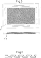
- the MEA used in Fig. 4 may be preferably prepared, as shown in the partially enlarged view of Fig. 5 , for example, by joining a catalyst layer to both surfaces of a solid polymer electrolyte membrane, sandwiching both surfaces of the catalyst layer with carbon paper or the like working out to a gas diffusing layer, thereby fabricating a five-layer structure, and covering its outer circumference with an insulating thermoplastic resin composition, but the present invention is not limited thereto.
- the material for the frame body part is a thermoplastic resin composition containing at least one same polymer out of the components contained in the separator of the present invention or containing a compatibilizer or that the polymer constituting the separator and the material for the frame body part of an MEA are thermoplastic resin compositions containing respective components working out to a pair of polymers having miscibility or compatibility, whereby the packingless stack unit shown in Fig. 4 can be fabricated.
- the melting point measuring method for use in the present invention is not particularly limited, but the melting point may be measured, for example, by the DSC method described in JIS K7121. In the present invention, the melting point was measured by DSC-7 manufactured by Perkin-Elmer.
- the miscibility means that the polymers have a capability of forming a single phase as a result of their melting and mixing.
- the thermodynamic requirement may be that the Gibbs free energy of mixing ⁇ G is less than zero ( ⁇ G ⁇ 0), and whether a single phase or not can be confirmed by a scattering method (e.g., light scattering, X-ray scattering, neutron scattering) (see, Polymer ABC Handbook, compiled by Kobunshi ABC Kenkyu Kai, the Society of Polymer Science, Japan, page 4 and page 196 , and D.R. Paul, Encycl. Polym. Sci. Eng., Vol. 12, page 399, John Wiley & Sons (1988 )).
- a scattering method e.g., light scattering, X-ray scattering, neutron scattering
- Examples of the combination having miscibility include polypropylene/polypropylene (a combination differing in the molecular weight, molecular weight distribution or the like), high-density polyethylene/high-density polyethylene (a combination differing in the molecular weight, molecular weight distribution or the like), polyphenylene ether/polystyrene, polypropylene/polybutene-1, and polymethyl methacrylate/polyvinyl acetate.
- the compatibility means that the polymers are non-miscible, but have some ability of effecting interfacial bonding between the polymers.
- Examples of the combination having compatibility include the followings.
- the compatibilizer is a polymer which works as a surfactant for polymers A and B incapable of being mixed and decreases the free energy at the interface. Accordingly, a polymer having miscibility and compatibility also has a function as a compatibilizer.
- both the separator and the MEA frame body part contain at least one same polymer, at least one member contains a compatibilizer, or these members are a combination working out to a pair of polymers having miscibility or compatibility.
- a component having a functional group capable of adhering to the separator or MEA frame body part through a chemical reaction may be incorporated, if desired.
- this adhesive functional group include, but are not limited to, a polymer or monomer having a hydroxyl group, a carboxyl group, an amino group, an epoxy group, an isocyanate group, a glycidyl methacrylate group, a carbonyl group, an acryl group, a maleic anhydride group, a silyl group or an amine-based functional group.
- the mass ratio of the component (A) to the component (B) in the electrically conducting resin composition usable in the present invention ranges from 2 to 20. If the mass ratio (A)/(B) is less than 1, insufficient electrical conductivity tends to result, whereas if the mass ratio (A)/(B) exceeds 20, the processability tends to deteriorate.
- the component (A) which is a carbonaceous material for use in the present invention includes one species or a combination of two or more species selected from carbon black, carbon fiber, amorphous carbon, expanded graphite, artificial graphite, natural graphite, kish graphite, vapor grown carbon fiber, carbon nanotube and fullerene.
- Examples of the carbon black as one of the carbonaceous materials above include ketjen black and acetylene black obtained by incomplete combustion of natural gas or the like or by thermal decomposition of acetylene; furnace carbon obtained by incomplete combustion of hydrocarbon oil or natural gas; and thermal carbon obtained by thermal decomposition of natural gas.
- the carbon fiber includes a pitch type prepared from heavy oil, by-product oil, coal tar and the like, and a PAN type prepared from polyacrylonitrile.
- Examples of the method for obtaining the amorphous carbon include a method of curing a phenol resin and subjecting the cured product to firing and grinding into a powder, and a method of curing a phenol resin in a spherical amorphous powder state and firing the cured product.
- a heat treatment at 2,000°C or more may be suitably performed.
- the expanded graphite powder is, for example, a powder obtained by dipping a graphite with a highly developed crystal structure, such as natural graphite or pyrolytic graphite, in a strongly oxidative solution, such as a mixed solution of concentrated sulfuric acid and nitric acid or a mixed solution of concentrated sulfuric acid and hydrogen peroxide water, to produce a graphite intercalation compound and after water washing, rapidly heating the compound, thereby expanding the graphite crystal in the C axis direction, or a powder obtained by once rolling the powder above into a sheet and grinding the sheet.
- a strongly oxidative solution such as a mixed solution of concentrated sulfuric acid and nitric acid or a mixed solution of concentrated sulfuric acid and hydrogen peroxide water
- the kish graphite is a planarly crystallized carbon precipitated along the temperature drop of melted pig iron in the hot metal preliminary treatment or the like.
- the kish graphite is generated as a matter mixed in slug or iron oxide and therefore, a high-purity kish graphite is recovered by beneficiation and further ground to finish a powder in a size suitable for usage.
- a coke is usually first produced.
- a petroleum-based pitch, a coal-based pitch or the like is used.
- Such a raw material is carbonized into a coke.
- the method for forming a graphite powder from the coke may generally include a method of grinding and then graphitizing the coke, a method of graphitizing the coke itself and then grinding it, and a method of adding a binder to the coke, molding and firing the mixture, and subjecting the fired product (the coke and this fired product are collectively called a coke and the like) to graphitization and then grinding into a powder.
- the crystal may be preferably not developed as much as possible and therefore, those heat-treated at 2,000°C or less, preferably 1,200°C or less, may be suitable.
- Examples of the graphitization method which can be used include a method using an Acheson furnace where the powder is charged into a graphite crucible and a current is directly passed thereto, and a method of heating the powder by a graphite heating element.
- the carbonaceous material from 0.05 to 5 mass% of boron may be preferably contained. If the boron amount is less than 0.05 mass%, the objective graphite powder having high electrical conductivity tends to be hardly obtained, whereas even if the boron is contained in excess of 5 mass%, this tends to scarcely contribute to enhancing the electrical conductivity of the carbon material.
- the method for measuring the amount of boron contained in the carbonaceous material is not particularly limited. In the present invention, a value measured by the inductively-coupled plasma emission spectrometry (hereinafter simply referred to as "ICP") or inductively-coupled plasma emission and mass spectrometry (hereinafter simply referred to as "ICP-MS”) is used.
- ICP inductively-coupled plasma emission spectrometry
- ICP-MS inductively-coupled plasma emission and mass spectrometry
- a sample after adding thereto sulfuric acid and nitric acid is decomposed under microwave heating (230°C) (digester method) and further decomposed by adding perchloric acid (HClO 4 ), and the decomposition product is diluted with water and analyzed by an ICP emission analyzer to measure the amount of boron.
- a boron source such as B simple element, B 4 C, BN, B 2 O 3 and H 3 BO 3 is added to a simple substance such as coke, pitch, natural graphite, artificial graphite, kish graphite, expanded graphite, carbon black, carbon fiber, vapor grown carbon fiber and carbon nanotube, or a mixture of one or more species thereof and after thoroughly mixing, the obtained mixture is graphitized at about 2,300 to 3,200°C, whereby boron can be incorporated into the carbonaceous material. If the boron compound is non-uniformly mixed, not only a non-uniform graphite powder is obtained but also sintering occurs highly probably at the graphitization.
- the boron source may be preferably formed into a powder having a particle diameter of 50 ⁇ m or less, preferably about 20 ⁇ m or less, and then mixed with the powder such as coke.
- the boron is contained is not particularly limited as long as boron and/or a boron compound is mixed in the graphite, but suitable examples thereof include a mode where boron is present between layers of the graphite crystal, and a mode where a part of carbon atoms constituting the graphite crystal are substituted by boron atom.
- the bond between boron atom and carbon atom may be in any bonding form such as covalent bonding and ion bonding.
- a high-speed rotary grinder e.g., hammer mill, pin mill, cage mill
- a ball mill of various types e.g., rolling mill, vibrating mill, planetary mill
- a stirring mill e.g., bead mill, attritor, circulating tube-type mill, annular mill
- a screen mill, a turbo-mill, a supermicron mill or a jet mill, which are a pulverizer may also be used by selecting the conditions.
- the coke, natural graphite or the like is ground using such a grinder and at this time, the average particle diameter and particle size distribution may be preferably controlled by selecting the grinding conditions and if desired, classifying the powder.
- the classification of coke powder, artificial graphite powder, natural graphite powder and the like may be performed by any method as long as the particles can be separated, but for example, a sieve classification method or an air classifier such as forced vortex-type centrifugal classifier (e.g., micron separator, turbo-plex, turbo-classifier, superseparator) or inertial classifier (e.g., modified virtual impactor, elbow jet) may be used.
- a sieve classification method or an air classifier such as forced vortex-type centrifugal classifier (e.g., micron separator, turbo-plex, turbo-classifier, superseparator) or inertial classifier (e.g., modified virtual impactor, elbow jet) may be used.
- a wet sedimentation or centrifugal classification method may also be used.
- the component (A) for use in the present invention may preferably contain a vapor grown carbon fiber and/or a carbon nanotube in an amount of 0.1 to 50 mass%.
- This content may be more preferably from 0.1 to 45 mass%, still more preferably from 0.2 to 40 mass%. If the content is less than 0.1 mass%, an effect of enhancing the electrical conductivity can be hardly obtained, whereas if the content exceeds 50 mass%, moldability tends to worsen.
- the vapor grown carbon fiber or carbon nanotube may preferably contain boron in an amount of 0.05 to 5 mass%, more preferably from 0.06 to 4 mass%, still more preferably from 0.06 to 3 mass%. If the boron content is less than 0.05 mass%, the electrical conductivity-enhancing effect by the addition of boron is small, whereas if boron added in excess of 5 mass%, the impurity amount may increase and this tends to readily cause deterioration in other physical properties.
- the vapor grown carbon fiber is a carbon fiber having a fiber length of about 0.5 to 10 ⁇ m and a fiber diameter of 200 nm or less, which is obtained, for example, by using, as a raw material, an organic compound such as benzene, toluene, natural gas and hydrocarbon-based gas, and performing a thermal decomposition reaction at 800 to 1,300°C together with hydrogen gas in the presence of a transition metal catalyst such as ferrocene.
- the size of the fiber diameter may be preferably 160 nm or less, more preferably 120 nm or less. A size exceeding 200 nm may be not preferred because the effect of obtaining high electrical conductivity decreases.
- the fiber may be preferably then graphitized at about 2,300 to 3,200°C, more preferably graphitized together with a graphitization catalyst such as boron, boron carbide, beryllium, aluminum and silicon at about 2,300 to 3,200°C in an inert gas atmosphere.
- a graphitization catalyst such as boron, boron carbide, beryllium, aluminum and silicon
- the carbon nanotube not only its mechanical strength but also its field emission function and hydrogen storage function are recently taken notice of in industry, and its magnetic function also starts attracting attention.
- This type of carbon nanotube is also called graphite whisker, filamentous carbon, graphite fiber, extra-fine carbon tube, carbon tube, carbon fibril, carbon microtube, carbon nanofiber or the like and has a fiber diameter of about 0.5 to 100 nm.
- the carbon nanotube includes a single-layer carbon nanotube where the graphite film constituting the tube comprises a single layer, and a multilayer carbon nanotube where the graphite film comprises multiple layers. In the present invention, either a single-layer carbon nanotube or a multilayer carbon nanotube can be used, but a single-layer carbon nanotube may be preferred, because a composition having higher electrical conductivity and higher mechanical strength tends to be obtained.
- the carbon nanotube may be obtained, for example, by producing a carbon nanotube by an arc discharge method, a laser evaporation method, a thermal decomposition method or the like described in Saito and Bando, Carbon Nanotube no Kiso (Basis of Carbon Nanotube), pp. 23-57, Corona Publishing Co., Ltd. (1998 ), and further purifying it by a hydrothermal method, a centrifugal separation method, an ultrafiltration method, an oxidation method or the like so as to enhance the purity.
- the carbon nanotube may be more preferably high-temperature treated in an inert gas atmosphere at about 2,300 to 3,200°C, still more preferably high-temperature treated in an inert gas atmosphere at about 2,300 to 3,200°C together with a graphitization catalyst such as boron, boron carbide, beryllium, aluminum and silicon.
- a graphitization catalyst such as boron, boron carbide, beryllium, aluminum and silicon.
- the average particle diameter of the component (A) was measured by a laser diffraction scattering method (using an apparatus, Microtrack HRA, manufactured by Nikkiso Co., Ltd.). As for the measurement conditions, 50 mg of a sample was weighed and added to 50 ml of distilled water, 0.2 ml of an aqueous 2% Triton (surfactant, produced by Wako Pure Chemical Industries, Ltd.) solution was added thereto and after ultrasonic wave dispersion for 3 minutes, the number average particle diameter was measured.
- Triton surfactant, produced by Wako Pure Chemical Industries, Ltd.
- the fiber as used herein indicates a fiber having a (length of long axis/length of short axis) ratio of 10 or more).
- the main component (a component accounting for 50 mass% or more) contained in the component (B) (thermoplastic resin composition) for use in the present invention include a thermoplastic resin comprising one species or a combination of a plurality of species selected from an acrylonitrile butadiene styrene copolymer, polystyrene, acrylic resin, polyvinyl chloride, polyimide, a liquid crystal polymer, polyether ether ketone, fluororesin, polyolefin, polyacetal, polyamide, polyethylene terephthalate, polybutylene terephthalate, polycarbonate, polycycloolefin, polyphenylene sulfide, polyethersulfone, polyphenylene oxide and polyphenylenesulfone.
- a thermoplastic resin comprising one species or a combination of a plurality of species selected from an acrylonitrile butadiene styrene copolymer, polystyrene, acrylic resin, polyvinyl chlor
- the main component is preferably a thermoplastic resin comprising one species or a plurality of species selected from polyolefin, fluororesin, polybutylene terephthalate, polyphenylene sulfide, a liquid crystal polymer, polyether ether ketone, polycycloolefin and polyethersulfone each having a melting point of 100°C or more and also from polycarbonate, polystyrene and polyphenylene oxide each having a glass transition temperature of 100°C or more.
- a thermoplastic resin comprising one species or a plurality of species selected from polyolefin, fluororesin, polybutylene terephthalate, polyphenylene sulfide, a liquid crystal polymer, polyether ether ketone, polycycloolefin and polyethersulfone each having a melting point of 100°C or more and also from polycarbonate, polystyrene and polyphenylene oxide each having a glass transition temperature of 100°C or more.
- a crystalline hydrocarbon-based polymer having a melting point of 100°C or more, more preferably 110°C or more, still more preferably 120°C or more. If the melting point is less than 100°C, the separator tends to creep.
- the melting point is not particularly limited in its measurement but may be measured according to JIS K7121 by using a differential scanning calorimeter (DSC7) manufactured by Perkin-Elmer.
- DSC7 differential scanning calorimeter manufactured by Perkin-Elmer.
- crystalline hydrocarbon-based polymer examples include polypropylene, polyethylene, polybutene, polymethylpentene and syndiotactic polystyrene.
- the separator can be made resistant to cracking by incorporating an elastomer into the component (B) in an amount of 0.05 to 30 mass%, preferably from 1 to 30 mass%, more preferably from 5 to 25 mass%. If the elastomer content is less than 0.05 mass%, the impact resistance may not be enhanced, whereas if the content exceeds 30 mass%, insufficient rigidity may result and incur deformation of the flow path or worsening of the gas impermeability.
- the elastomer for use in the present invention tends to be easily dispersed in the component (B) when the average particle diameter is 5 ⁇ m or less, and by making the average particle diameter smaller than the average particle diameter or the average fiber length of the component (A), electrical conductivity and toughness can be enhanced.
- the average particle diameter may be preferably 4 ⁇ m or less, more preferably 3 ⁇ m or less. If the average particle diameter exceeds 5 ⁇ m, the separator may be readily broken and electrical conductivity also tends to worsen.
- the elastomer for use in the present invention is a polymer having rubbery elasticity in the vicinity of ordinary temperature.
- the elastomer which can be used is, for example, one species or a combination of two or more species selected from acrylonitrile butadiene rubber, hydrogenated nitrile rubber, styrene butadiene rubber, an ethylene-propylene copolymer, an ethylene-octene copolymer, an ethylene-butene copolymer, a propylene-butene copolymer, ethylene-propylene-diene terpolymerization rubber, ethylene butadiene rubber, fluororubber, isoprene rubber, silicone rubber, acrylic rubber, butadiene rubber, high styrene rubber, chloroprene rubber, urethane rubber, polyether-based special rubber, ethylene tetrafluoride/propylene rubber, epichlorohydrin rubber, norbornene rubber, butyl rubber,
- hydrolysis resistance is one species or a combination of two or more species selected from hydrocarbon-based elastomers, in other words, styrene butadiene rubber, an ethylene-propylene copolymer, an ethylene-octene copolymer, an ethylene-butene copolymer, a propylene-butene copolymer, ethylene-propylene-diene terpolymerization rubber, ethylene butadiene rubber, isoprene rubber, butadiene rubber, a styrene-based thermoplastic elastomer, an olefin-based thermoplastic elastomer and a 1,2-polybutadiene-based thermoplastic elastomer.
- hydrocarbon-based elastomers in other words, styrene butadiene rubber, an ethylene-propylene copolymer, an ethylene-octene copolymer, an ethylene-butene copolymer, a propy
- styrene-based thermoplastic elastomer examples include hydrogenated styrene butadiene rubber, a styrene ethylene-butylene styrene block copolymer, a styrene ethylene-propylene styrene block copolymer, an olefin crystal ethylene-butylene olefin crystal block copolymer, a styrene ethylene-butylene olefin crystal block copolymer, a styrene isoprene styrene block copolymer, and a styrene butadiene styrene block copolymer.
- hydrogenated styrene butadiene rubber a styrene ethylene-butylene styrene block copolymer and a styrene ethylene-propylene styrene block copolymer.
- the number average particle diameter of the elastomer component dispersed in the component (B) was determined from 100 particles by preparing an ultrathin slice from the cross section of a liquid nitrogen-frozen sample by means of an ultramicrotome (ULTRACUT N, manufactured by Reichert Inc.), dyeing it with osmium, observing the particle diameter of the dispersion phase through TEM (JEM-1230, manufactured by JEOL Ltd.), and analyzing the TEM image by an image analyzing system (Luzex, manufactured by Nireco Corp.).
- thermoplastic resin composition which is the component (B) of the present invention
- one or more members of an antioxidant, a halogen scavenger, an ultraviolet absorbent and the like may be previously added, if desired, in the range giving a total amount of 0.01 to 5 parts by weight per 100 parts by weight of the component (B).
- an additive comprising one species or a combination of two or more species selected from an antioxidant, an ultraviolet absorbent, a lubricant, a reinforcing material (e.g., glass fiber, whisker, organic fiber, carbon fiber), a flame retardant, a surfactant and a surface modifier (e.g., hydrophilicity-imparting agent, water repellency-imparting agent, slidability-imparting agent), may be incorporated in a total amount of 0.01 to 20 mass% for the purpose of improving the hardness, strength, electrical conductivity, moldability, durability, weather resistance, water resistance, surface property and the like.
- a surface modifier e.g., hydrophilicity-imparting agent, water repellency-imparting agent, slidability-imparting agent
- the electrically conducting resin composition for use in the present invention is not particularly limited in its production process, but for example, in the production process of the electrically conducting resin composition, respective components described above may be preferably mixed as uniformly as possible by using a kneader generally used in the field of resin, such as roll mill, extruder, kneader and Banbury mixer.
- a kneader generally used in the field of resin, such as roll mill, extruder, kneader and Banbury mixer.
- the electrically conducting resin composition for use in the present invention may be, after kneading or mixing, ground or granulated for the purpose of facilitating the supply of the material to the molding machine or mold.
- a homogenizer e.g., a Wiley grinder, a high-speed rotary grinder (e.g., hammer mill, pin mill, cage mill, blender) or the like may be used, and the grinding may be preferably performed while cooling so as to prevent the material from aggregating with each other.
- the granulation includes a method of pelletizing the material by using an extruder, a Ruder, a co-kneader or the like, and a method using a pan-type granulator or the like.
- an electrically conducting resin composition comprising a carbonaceous material and a thermoplastic resin composition is formed into a sheet, and the sheet is heated to the melting temperature, inserted into a mold set to not more than the solidification temperature of the sheet, and then subjected to stamp-molding to obtain the separator.
- the thickness of the sheet suitable for high-speed molding may be preferably from 0.05 to 2 mm.
- the thickness of the sheet may be more preferably from 0.1 to 1.5 mm, still more preferably from 0.1 to 1.0 mm. If the thickness is less than 0.05 mm, the separator may be readily broken, whereas if it exceeds 2 mm, the yield may decrease.
- a continuous sheet or a sheet cut into an appropriate size is fed to the mold.
- the sheet is heated in the preceding step.
- the heating of the sheet is not limited in its method, but may be performed, for example, by one or more methods selected from infrared heating, induction heating, warm air heating, hot plate heating and microwave heating. For performing the heating at a high speed, infrared heating and induction heating may be preferred. More preferably, the sheet heated may be fed directly to the mold from the extrusion molding machine.
- the processing method of the sheet is selected from a method by an extruder, a method by a combination of an extruder and a mill roll, and a method of feeding a powdery material to the roll.
- the temperature of the mill roll may be preferably set to not more than the solidification temperature of the sheet.
- the performance or accuracy of the separator can be more enhanced by forming the sheet in a multilayer structure comprising two or more layers.
- flowability and in turn accuracy may be enhanced.
- the flexural modulus of the surface layer is set to 1/2 or less in terms of the ratio to the modulus of the center layer (modulus of surface layer/modulus of center layer)
- the adhesion on stacking may be enhanced to reduce the contact resistance and therefore, the output density may increase.
- the modulus may be more preferably 1/3 or less, still more preferably 1/5 or less. If the modulus exceeds 1/2, the contact resistance when stacked tends to worsen.
- the flexural modulus was measured according to JIS K7171 under the conditions of a specimen of 40x10x2 mm, a test speed of 1 mm/min and a support-to-support distance of 30 mm.
- the time after the sheet heated to the melting temperature is fed to the mold until the pressure intensification is completed by closing the mold may be preferably 10 seconds or less, more preferably 5 seconds or less, still more preferably 3 seconds or less. If the time exceeds 10 seconds, the heated sheet may be solidified.
- the stamp-molding is performed by holding the pressure for 5 seconds or less, and the molded article is taken out from the mold, whereby a corrugated separator shown in Fig. 2 can be obtained.
- the mold temperature is set to not more than the solidification temperature of the material, but for more enhancing the transferability or accuracy, the mold temperature may be preferably controlled by a system capable of elevating or lowering the temperature.
- the gas seal part may be preferably formed of an insulating resin composition having a compressive permanent strain of 80% or less (in accordance with JIS K6301, test conditions: 70°C, 25% compressive strain, 500 hours), because the gas seal part can be sealed by only clamping a stack.
- the seal part may be more preferably welded.
- an ultrasonic wave, a laser and a high-frequency wave may be preferably used, because welding can be topically performed and deformation of the separator can be avoided.
- welding can be performed by contacting an ultrasonic horn in a pressure-applied state with the welding site assigned to a triangular protrusion which becomes an energy director.
- a high-output semiconductor laser or a YAG laser may be preferred, and welding can be performed by forming the insulating part from a laser-transmitting composition and irradiating the laser while applying a pressure to the site to be welded.
- the seal part may also be joined by a heat-seal method or with an adhesive.
- a non-needle coke As the carbonaceous material, a non-needle coke, MC Coke, produced by MC Carbon K.K. was coarsely ground to a size of 2 to 3 mm by a pulverizer (manufactured by Hosokawamicron Corp.), and the coarsely ground product was finely ground by a jet mill (IDS2UR, manufactured by Nippon Pneumatic Mfg. Co., Ltd.) and then adjusted to a desired particle diameter by classification. The particle of 5 ⁇ m or less was removed by air classification using a turbo-classifier (TC15N, manufactured by Nisshin Engineering Inc.).
- a turbo-classifier T15N, manufactured by Nisshin Engineering Inc.
- the number average particle diameter of H-SBR dispersed in PP was observed by TEM (JEM-1230, manufactured by JEOL Ltd.) and found to be 0.08 ⁇ m.
- the obtained graphite resin composition was formed into a sheet having a width of 60 mm and a thickness of 3 mm at a molding temperature of 210°C by using a ⁇ 40 single-screw extruder (manufactured by Tanabe Plastics Machinery Co., Ltd.). Furthermore, the sheet heated at 210°C was sent to a mill roll at 100°C and rolled to obtain a sheet having a width of 100 mm and a thickness of 1 mm.
- the 1 mm-thick sheet was uniformly heated to 240°C by a halogen lamp (manufactured by Iwasaki Electric Co., Ltd.), and the sheet was further fed in 2 seconds between mold shells at 95°C disposed in a 50-t press molding machine and stamped under a pressure of output 80% for 3 seconds to obtain a corrugated separator.
- Fig. 6 shows the cross-sectional shape of the flow path in the obtained separator.
- the recess of the flow path part had a curved shape and in the projection, a flat part was ensured and the offset of the flat part was 0.3 mm.
- the separator shape was such that the area was 65x65 mm, the groove width was 1 mm, the groove depth was 0.5 mm, and the flow path on one surface was a serpentine flow path.
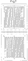
- Fig. 7 shows the overall view. Also, the density was 1.83 g/cm 3 , the wall thickness in the thinnest part of the flow path was 0.3 mm, the maximum wall thickness/minimum wall thickness ratio was 1.4, and the contact resistance with carbon paper (TGP-H-060, produced by Toray Industries, Inc.) was 6 m ⁇ cm 2 .
- Example 2 Using the same graphite resin composition as that in Example 1, a sheet having a width of 60 mm and a thickness of 3 mm was extrusion molded at a molding temperature of 210°C in the same manner. The sheet heated at 210°C was sent to a mill roll at 100°C and rolled to obtain a sheet having a width of 100 mm and a thickness of 1.5 mm.
- the 1.5 mm-thick sheet was uniformly heated to 240°C by a halogen lamp, and the sheet was further fed in 2 seconds between mold shells at 95°C disposed in a 50-t press molding machine and stamped under a pressure of output 80% for 10 seconds to obtain a separator having a cross-sectional shape shown in Fig. 8 where the flow path was symmetric from front to back.
- the recess of the flow path part did not have a curved shape and in the projection, a flat part was ensured and the offset of the flat part was 2 mm.
- the separator shape was similarly to Example 1 such that the area was 65x65 mm, the groove width was 1 mm, the groove depth was 0.5 mm, and the flow path on one surface was a serpentine flow path ( Fig. 9 ). Also, the density was 1.80 g/cm 3 , the wall thickness in the thinnest part of the flow path was 0.3 mm, the maximum wall thickness/minimum wall thickness ratio was 4.3, and the contact resistance with carbon paper (TGP-H-060, produced by Toray Industries, Inc.) was 7.1 m ⁇ cm 2 .
- a non-needle coke As the carbonaceous material, a non-needle coke, MC Coke, produced by MC Carbon K.K. was coarsely ground to a size of 2 to 3 mm by a pulverizer (manufactured by Hosokawamicron Corp.), and the coarsely ground product was finely ground by a jet mill (IDS2UR, manufactured by Nippon Pneumatic Mfg. Co., Ltd.) and then adjusted to a desired particle diameter by classification. The particle of 5 ⁇ m or less was removed by air classification using a turbo-classifier (TC15N, manufactured by Nisshin Engineering Inc.).
- a turbo-classifier T15N, manufactured by Nisshin Engineering Inc.
- VGCF vapor grown carbon fiber
- B 4 C boron carbide
- the crucible was then placed in a graphitizing furnace with a graphite heater and after the inside of the furnace was once vacuumized and replaced with an argon gas, the powder was graphitized at an inner pressure of 1.2 atm and a temperature of 2,800°C under a stream of argon gas atmosphere. The powder was further left standing to cool in an argon gas atmosphere and then taken out to obtain 0.94 kg of Graphite Fine Powder (A2).
- Graphite Resin Composition (C2) was produced by kneading Graphite Fine Powder (A2) together with the polypropylene and hydrogenated styrene butadiene rubber used in Example 1 at the same compositional ratio, and the composition was further formed into a sheet and stamp-molded under the same conditions as in Example 1 to obtain a separator having the same corrugated shape as in Example 1.
- the density was 1.82 g/cm 3
- the wall thickness in the thinnest part of the flow path was 0.3 mm
- the maximum wall thickness/minimum wall thickness ratio was 1.4
- the contact resistance with carbon paper TGP-H-060, produced by Toray Industries, Inc.
- the same graphite resin composition as that in Example 2 was formed into a sheet and stamp-molded in the same manner as in Comparative Example 1 to obtain a separator having the same shape as that in Comparative Example 1.
- the density was 1.81 g/cm 3
- the wall thickness in the thinnest part of the flow path was 0.3 mm
- the maximum wall thickness/minimum wall thickness ratio was 4.3
- the contact resistance with carbon paper (TGP-H-060, produced by Toray Industries, Inc.) was 6.8 m ⁇ cm 2 .
- carbonaceous material 14.85 kg of natural graphite (high-purity natural graphite ACP, produced by Nippon Graphite Industries, Ltd., average particle diameter: 24 ⁇ m) and 0.15 kg of boron carbide (B 4 C) were added and mixed in a Henschel mixer at 800 rpm for 5 minutes.
- natural graphite high-purity natural graphite ACP, produced by Nippon Graphite Industries, Ltd., average particle diameter: 24 ⁇ m
- B 4 C boron carbide
- Graphite Fine Powder (A1) produced in Example 1, 35 mass% of Graphite Fine Powder (A3, natural graphite), 13.2 mass% of polypropylene (SunAllomer (registered trademark) PC630A, produced by SunAllomer Ltd.) and 1.8 mass% of propylene ⁇ -olefin copolymer (Tafmer (registered trademark) XM-7080, produced by Mitsui Chemicals, Inc.) were kneaded in a pressure kneader (MIX-LABO, manufactured by Moriyama Co., Ltd.) at a temperature of 200°C and 40 rpm for 5 minutes to obtain Graphite Resin Composition (C3).
- MIX-LABO manufactured by Moriyama Co., Ltd.
- Graphite Resin Composition (C3) was formed into a sheet having a width of 60 mm and a thickness of 3 mm at a molding temperature of 210°C by using a ⁇ 40 single-screw extruder, and the sheet heated was sent to a mill roll at 100°C and rolled to obtain a sheet having a width of 60 mm and a thickness of 0.1 mm.
- the sheet having a width of 60 mm and a thickness of 3 mm of Graphite Resin Composition (C1) extrusion-molded in Example 1 was sandwiched by the sheet of Graphite Resin Composition (C3) above, and the sheet assembly was roll-molded to obtain a three-layer sheet having a width of 100 mm and a thickness of 1 mm (structure (layer thickness): C3 (0.03 mmt)/C1 (0.94 mmt)/C3 (0.03 mmt)).
- This three-layer sheet was uniformly heated to 240°C by a halogen lamp, and the sheet was further fed in 2 seconds between mold shells at 95°C disposed in a 50-t press molding machine and stamped under a pressure of output 80% for 3 seconds to obtain a separator having the same corrugated shape as in Example 1.
- the density was 1.83 g/cm 3
- the wall thickness in the thinnest part of the flow path was 0.3 mm
- the maximum wall thickness/minimum wall thickness ratio was 1.4
- the contact resistance with carbon paper (TGP-H-060, produced by Toray Industries, Inc.) was 5.4 m ⁇ cm 2 .
- Graphite Resin Composition (C1) as the center layer had a flexural modulus of 8,500 MPa and a melting point of 165°C
- Graphite Resin Composition (C3) as the outer layer had a flexural modulus of 6,200 MPa and a melting point of 128°C.
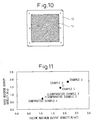
- an MEA weldable with this separator was prepared as follows. An MEA of 50x50 mm was inserted into a mold, and Insulating Thermoplastic Resin Composition (D1) shown in Table 1 was injected to obtain an MEA integrated with an insulating frame body shown in Fig. 10 .
- Nafion (registered trademark) 112 (produced by Du Pont) was used for the ion exchange membrane, and a platinum catalyst (TEC10V50E, produced by Tanaka Kikinzoku K.K.) was joined by Pt junction to the anode and the cathode each in an amount of about 0.5 mg/cm 2 to provide a power generation part area of 25 cm 2 (50x50 mm).
- Teflon (registered trademark)-treated carbon paper TGP-H-060, produced by Toray Industries, Ltd.
- This MEA was sandwiched by the separator produced in Example 3 such that the serpentine flow path came into contact with the MEA, and heat-sealed at 135°C under a pressure of 5 MPa for 10 seconds to produce a single cell unit. Since the sandwiched assembly was integrated by heat sealing, a gasket was not used and the number of parts could be decreased.
- Graphite Resin Composition (C1) was formed into a sheet having a width of 60 mm and a thickness of 3 mm
- Graphite Resin Composition (C3) was formed into a sheet having a width of 60 mm and a thickness of 0.1 mm, and after sandwiching the sheet to give a construction of C3/C1/C3, the sheet assembly was roll-molded to obtain a three-layer sheet having a width of 100 mm and a thickness of 1 mm (structure (layer thickness): C3 (0.03 mmt)/C1 (0.94 mmt)/C3 (0.03 mmt)).
- This sheet having a three-layer structure was uniformly heated to 240°C by a halogen lamp, and the sheet was further fed in 2 seconds between mold shells at 95°C disposed in a 50-t press molding machine and stamped under a pressure of output 80% for 3 seconds to obtain a separator having the same shape as that in Comparative Example 1.
- the density was 1.82 g/cm 3
- the wall thickness in the thinnest part of the flow path was 0.3 mm
- the maximum wall thickness/minimum wall thickness ratio was 4.3
- the contact resistance with carbon paper (TGP-H-060, produced by Toray Industries, Inc.) was 7 m ⁇ cm 2 .
- Graphite Resin Composition (C1) as the center layer had a flexural modulus of 8,500 MPa and a melting point of 165°C
- Graphite Resin Composition (C3) as the outer layer had a flexural modulus of 6,200 MPa and a melting point of 128°C.
- Example 3 the five-layer structure MEA produced in Example 3 with the outer circumference being an insulating thermoplastic resin composition was sandwiched by two sheets of the separator prepared above such that the serpentine flow path came into contact with the MEA, and heat sealing of the sandwiched assembly was tried at 135°C under a pressure of 5 MPa for 30 seconds, but a welding failure was brought about, despite heat sealing for a longer time than that in Example 3. Furthermore, heat sealing was tried at 150°C under a pressure of 5 MPa for 30 seconds, as a result, a single cell unit could be obtained, though the flow path part of the separator was slightly deformed.
- Example 3 The evaluation of a single cell was performed using the separators obtained in Examples 1 and 2 and Comparative Examples 1 and 2 and the single cell units obtained in Example 3 and Comparative Example 3.
- an MEA where Nafion (registered trademark) 112 (produced by Du Pont) was used for the ion exchange membrane and a platinum catalyst (TEC10V50E, produced by Tanaka Kikinzoku K.K.) was joined by Pt junction to the anode and the cathode each in an amount of about 0.5 mg/cm 2 to provide a power generation part area of 25 cm 2 (50x50 mm), was used.
- Teflon (registered trademark)-treated carbon paper TGP-H-060, produced by Toray Industries, Ltd.
- the power generation test was performed under the conditions of a cell temperature of 80°C, an anode dew point of 80°C, a cathode dew point of 70°C, a hydrogen flow rate of 500 ml/min, an air flow rate of 2,080 ml/min constant, and open-to-air on the outlet side.
- the temperature of the cell was controlled by attaching a rubber heater.
- Fig. 11 shows the output test results.
- the unit volume and unit mass were calculated respectively from the volume and mass of a single cell comprising a separator (two sheets), an MEA (one sheet), a gasket (two sheets) and a carbon paper (two sheets).
- the unit volume and unit mass were calculated from the volume and mass of the produced single cell unit. Accordingly, the results shown in Fig. 11 are the results compared by excluding the volume and mass of the metal plate or current collector plate sandwiching the single cell from both sides.
- the thickness of the separator could be reduced, a thin stack could be fabricated and the weight could be more decreased, so that the maximum output density could be greatly enhanced.
- the output density could be more enhanced.
- Example 3 when as in Example 3, a corrugated separator was used and a single cell was produced by welding, the contact resistance with the MEA could be reduced, the output density could be more enhanced by virtue of not using a gasket, and use of the unitized cell could shorten the fabrication time to 1/5 the time of Comparative Example 1.
Landscapes
- Chemical & Material Sciences (AREA)
- Life Sciences & Earth Sciences (AREA)
- Engineering & Computer Science (AREA)
- Manufacturing & Machinery (AREA)
- Sustainable Development (AREA)
- Sustainable Energy (AREA)
- Chemical Kinetics & Catalysis (AREA)
- Electrochemistry (AREA)
- General Chemical & Material Sciences (AREA)
- Composite Materials (AREA)
- Fuel Cell (AREA)
Claims (13)
- Separator für eine Brennstoffzelle, der eine elektrisch leitende Harzzusammensetzung enthält und einen elektrisch leitenden Strömungswegteil umfasst; wobei
die elektrisch leitende Harzzusammensetzung ein kohlenstoffhaltiges Material (A) und eine thermoplastische Harzzusammensetzung (B) in einem Massenverhältnis (A)/(B) von 2 bis 20 umfasst, wobei die Gesamtmasse von (A) und (B) 80 bis 100 Massen-% in der Zusammensetzung ausmacht;
der elektrisch leitende Strömungswegteil eine gewellte Form mit einer Aussparung und einem Vorsprung auf jeder der Vorder- und Rückoberflächen davon aufweist, wobei die Aussparung eine Rille für einen Strömungsweg darstellt, wobei der Boden einer Aussparung auf einer zweiten Hauptfläche zwischen der Spitze eines Vorsprungs und dem Boden einer Aussparung auf einer ersten Hauptfläche angeordnet ist, und die Tiefe der Aussparung 0,2 bis 1 mm ist; und
der elektrisch leitende Strömungswegteil eine Wanddicke von 0,05 bis 0,5 mm und ein Verhältnis maximale Wanddicke/minimale Wanddicke von 1 bis 2 aufweist, wobei die Wanddicke der minimale Abstand ist, der das Eindringen in den Strömungswegteil auf der Rückoberfläche von einem beliebigen Punkt des Strömungswegs auf der Vorderoberfläche erlaubt, und wobei im Querschnitt des Strömungswegteils ein Versatz angeordnet ist, der es erlaubt, dass flache Oberflächen der Vorsprünge um 0,05 bis 0,5 mm zwischen den Vorder- und Rückoberflächen überlappen. - Separator für eine Brennstoffzelle nach Anspruch 1, wobei die Dichte des Strömungswegteils 1,2 bis 2,5 g/cm3 ist.
- Separator für eine Brennstoffzelle nach Anspruch 1 oder 2, wobei die Aussparung des Strömungswegteils eine gekrümmte Form im Querschnitt und der Vorsprung eine flache Oberfläche aufweist.
- Separator für eine Brennstoffzelle nach einem der Ansprüche 1 bis 3, wobei die thermoplastische Harzzusammensetzung (B) eine Komponente mit einer Glasübergangstemperatur von -20°C oder weniger enthält.
- Separator für eine Brennstoffzelle nach einem der Ansprüche 1 bis 4, wobei die thermoplastische Harzzusammensetzung (B) 0,05 bis 30 Massen-% einer Elastomerkomponente (C) in Bezug auf die Gesamtmasse der thermoplastischen Harzzusammensetzung (B) enthält.
- Separator für eine Brennstoffzelle nach Anspruch 5, wobei der mittlere Teilchendurchmesser der Elastomerkomponente (C) 0,01 bis 5 µm und kleiner als der mittlere Teilchendurchmesser oder die mittlere Faserlänge des kohlenstoffhaltigen Materials (A) ist.
- Separator für eine Brennstoffzelle nach einem der Ansprüche 1 bis 6, wobei das kohlenstoffhaltige Material (A) 0,05 bis 5 Massen-% Bor in Bezug auf die Gesamtmasse des kohlenstoffhaltigen Materials (A) enthält.
- Separator für eine Brennstoffzelle nach einem der Ansprüche 1 bis 7, wobei das kohlenstoffhaltige Material (A) 0,1 bis 50 Massen-% in Bezug auf die Gesamtmasse des kohlenstoffhaltigen Materials (A) einer dampfphasengewachsenen Kohlenstofffaser und/oder eines Kohlenstoffnanoröhrchens mit jeweils einem Durchmesser von 200 nm oder weniger enthält.
- Separator für eine Brennstoffzelle nach einem der Ansprüche 1 bis 8, wobei natürliches Graphit in der elektrisch leitenden Harzzusammensetzung enthalten ist.
- Separator für eine Brennstoffzelle nach Anspruch 9, wobei der Separator eine Mehrschichtstruktur aufweist, wobei die erste elektrisch leitende Harzzusammensetzungsschicht eine Zentralschicht und die zweite elektrisch leitende Harzzusammensetzungsschicht eine Außenschicht ist und der Biegemodul der zweiten elektrisch leitenden Harzzusammensetzungsschicht 1/2 oder weniger des Biegemoduls der ersten elektrisch leitenden Harzzusammensetzungsschicht ist.
- Verfahren zum Herstellen eines Separators für eine Brennstoffzelle nach einem der Ansprüche 1 bis 10, welches die folgenden Stufen umfasst:das Erwärmen einer Lage, die eine elektrisch leitende Harzzusammensetzung umfasst, welche ein kohlenstoffhaltiges Material (A) und eine thermoplastische Harzzusammensetzung (B) in einem Massenverhältnis (A)/(B) von 2 bis 20 enthält, wobei die Gesamtmasse von (A) und (B) 80 bis 100 % in der Zusammensetzung ausmacht, auf die Schmelztemperatur der Lage, unddas Einsetzen der erwärmten Lage in eine Form, die auf nicht höher als die Verfestigungstemperatur der Lage eingestellt ist, und das anschließende Stempelformen der Lage.
- Verfahren zum Herstellen eines Separators für eine Brennstoffzelle nach Anspruch 11, wobei die Dicke der Lage 0,05 bis 2 mm ist.
- Verfahren zum Herstellen eines Separators für eine Brennstoffzelle nach Anspruch 11 oder 12, wobei das Stempelformen während 10 Sekunden oder weniger mit einer Kaltpressformmaschine nach dem Schließen der Form bis zum Abschluss der Druckintensivierung durchgeführt wird.
Applications Claiming Priority (2)
| Application Number | Priority Date | Filing Date | Title |
|---|---|---|---|
| JP2006268454A JP5068051B2 (ja) | 2006-09-29 | 2006-09-29 | 燃料電池用セパレータおよびその製造方法 |
| PCT/JP2007/069419 WO2008038835A1 (en) | 2006-09-29 | 2007-09-27 | Separator for fuel cell and production method thereof |
Publications (2)
| Publication Number | Publication Date |
|---|---|
| EP2067201A1 EP2067201A1 (de) | 2009-06-10 |
| EP2067201B1 true EP2067201B1 (de) | 2017-11-29 |
Family
ID=38752393
Family Applications (1)
| Application Number | Title | Priority Date | Filing Date |
|---|---|---|---|
| EP07829157.2A Not-in-force EP2067201B1 (de) | 2006-09-29 | 2007-09-27 | Separator für eine brennstoffzelle und herstellungsverfahren dafür |
Country Status (5)
| Country | Link |
|---|---|
| US (1) | US8252483B2 (de) |
| EP (1) | EP2067201B1 (de) |
| JP (1) | JP5068051B2 (de) |
| KR (1) | KR101125076B1 (de) |
| WO (1) | WO2008038835A1 (de) |
Families Citing this family (13)
| Publication number | Priority date | Publication date | Assignee | Title |
|---|---|---|---|---|
| JP4897928B2 (ja) * | 2009-03-24 | 2012-03-14 | パナソニック株式会社 | 固体高分子形燃料電池および固体高分子形燃料電池用セパレータ |
| JP2011228059A (ja) | 2010-04-16 | 2011-11-10 | Sumitomo Electric Ind Ltd | レドックスフロー電池用双極板 |
| US9642192B2 (en) * | 2011-08-04 | 2017-05-02 | Fuelcell Energy, Inc. | Method and manufacturing assembly for sintering fuel cell electrodes and impregnating porous electrodes with electrolyte powders by induction heating for mass production |
| JP5594318B2 (ja) * | 2012-05-24 | 2014-09-24 | 株式会社村田製作所 | スイッチモジュール |
| CN105103351B (zh) * | 2013-04-11 | 2017-07-07 | 昭和电工株式会社 | 碳构件、碳构件的制造方法、氧化还原液流电池和燃料电池 |
| DE102014005930A1 (de) * | 2013-05-05 | 2014-11-20 | Daimler Ag | Hybride Bipolarplatten-Anordnung für Brennstoffzellen |
| JP5915613B2 (ja) * | 2013-10-02 | 2016-05-11 | トヨタ自動車株式会社 | セパレータおよび燃料電池 |
| KR102067381B1 (ko) * | 2015-10-28 | 2020-01-17 | 니뽄 도쿠슈 도교 가부시키가이샤 | 인터커넥터-전기 화학 반응 단셀 복합체, 전기 화학 반응 셀 스택 및 인터커넥터-전기 화학 반응 단셀 복합체의 제조 방법 |
| KR102071906B1 (ko) * | 2016-12-02 | 2020-01-31 | 주식회사 엘지화학 | 분리판, 및 이를 포함하는 연료전지 스택 |
| JP6922752B2 (ja) * | 2018-01-15 | 2021-08-18 | トヨタ自動車株式会社 | 伝熱部材、電池パック、及び車両 |
| KR102696762B1 (ko) * | 2019-09-26 | 2024-08-21 | 도요보 가부시키가이샤 | 연료 전지용 접합체 및 적층체 |
| CN114641878B (zh) * | 2020-02-06 | 2024-08-06 | Nok株式会社 | 隔板一体型密封垫及其制造方法 |
| JP7415839B2 (ja) | 2020-08-05 | 2024-01-17 | トヨタ自動車株式会社 | 燃料電池用セパレータ及びその製造方法 |
Citations (2)
| Publication number | Priority date | Publication date | Assignee | Title |
|---|---|---|---|---|
| JP2005100703A (ja) * | 2003-09-22 | 2005-04-14 | Asahi Organic Chem Ind Co Ltd | 導電性成形材料、これを用いてなる燃料電池用セパレータ及びその製造方法 |
| WO2005055351A1 (en) * | 2003-12-05 | 2005-06-16 | Showa Denko K.K. | Electroconductive resin composition and molded product thereof |
Family Cites Families (26)
| Publication number | Priority date | Publication date | Assignee | Title |
|---|---|---|---|---|
| JPH0622135B2 (ja) | 1984-01-11 | 1994-03-23 | 昭和電工株式会社 | 電池用炭素質セパレータの製造法 |
| JPH03105863A (ja) * | 1989-09-19 | 1991-05-02 | Tokai Carbon Co Ltd | 燃料電池用炭素質複合部材とその製造方法 |
| JP3383953B2 (ja) | 1995-02-09 | 2003-03-10 | 東海カーボン株式会社 | 固体高分子型燃料電池用黒鉛部材の製造方法 |
| JP2001068128A (ja) | 1999-06-24 | 2001-03-16 | Unitika Ltd | 燃料電池用セパレータ及びその製造方法 |
| JP2001052721A (ja) | 1999-08-12 | 2001-02-23 | Osaka Gas Co Ltd | 燃料電池用セパレータおよびその製造方法 |
| CA2323827A1 (en) * | 1999-10-20 | 2001-04-20 | Atsushi Miyazawa | Carbonaceous composite material, process for production thereof, fuel cell separator and polymer electrolyte fuel cell |
| JP2001122677A (ja) * | 1999-10-26 | 2001-05-08 | Osaka Gas Co Ltd | 燃料電池用セパレータの製造方法 |
| JP3706784B2 (ja) | 2000-01-11 | 2005-10-19 | 日本ピラー工業株式会社 | 燃料電池用セパレータの製造方法 |
| JP2001216977A (ja) | 2000-02-01 | 2001-08-10 | Tokai Carbon Co Ltd | 燃料電池用セパレータ材 |
| NL1014405C1 (nl) * | 2000-02-17 | 2001-08-20 | Nedstack Holding B V | Methode voor het vervaardigen Polymeer Elektrolyt Brandstofcellen. |
| EP1265303B1 (de) | 2000-03-07 | 2009-07-01 | Panasonic Corporation | Polymer-elektroly-brennstoffzelle und herstellungsverfahren dafür |
| JP2002008685A (ja) | 2000-06-26 | 2002-01-11 | Mitsubishi Plastics Ind Ltd | 燃料電池セル用セパレータ |
| US7049021B2 (en) * | 2000-06-29 | 2006-05-23 | Osaka Gas Company Limited | Conductive composition for solid polymer type fuel cell separator, solid polymer type fuel cell separator, solid polymer type fuel cell and solid polymer type fuel cell system using the separator |
| US6607857B2 (en) * | 2001-05-31 | 2003-08-19 | General Motors Corporation | Fuel cell separator plate having controlled fiber orientation and method of manufacture |
| EP1324411A3 (de) * | 2001-12-26 | 2004-12-22 | Mitsubishi Chemical Corporation | Verbundverkstoff für Spritzgiessen von Brennstoffzellenseparator und Verfahren zu dessen Herstellung, und Brennstoffzellenseparator mit diesem Verbundverkstoff und Verfahren zur dessen Herstellung |
| JP4414631B2 (ja) | 2002-03-20 | 2010-02-10 | 本田技研工業株式会社 | 燃料電池用セパレータの製造方法 |
| JP2003303598A (ja) * | 2002-04-11 | 2003-10-24 | Jfe Chemical Corp | 固体高分子型燃料電池用セパレータ成形用金型、該セパレータの製造方法およびセパレータ |
| JP2004345120A (ja) * | 2003-05-20 | 2004-12-09 | Meiki Co Ltd | 導電性材料の成形方法および装置 |
| JP2005032591A (ja) * | 2003-07-07 | 2005-02-03 | Nissan Motor Co Ltd | 燃料電池用セパレータ及びその製造方法 |
| JP2005228703A (ja) * | 2004-02-16 | 2005-08-25 | Nissan Motor Co Ltd | 燃料電池 |
| JP2005235631A (ja) | 2004-02-20 | 2005-09-02 | Nok Corp | ガスケットの製造方法、セパレータの製造方法及びガスケット |
| JP2005285552A (ja) * | 2004-03-30 | 2005-10-13 | Nippon Steel Chem Co Ltd | 燃料電池セパレータ用組成物および燃料電池セパレータの製造方法 |
| US7687175B2 (en) * | 2004-05-03 | 2010-03-30 | Gm Global Technology Operations, Inc. | Hybrid bipolar plate assembly and devices incorporating same |
| US7611643B2 (en) | 2004-05-27 | 2009-11-03 | Showa Denko K.K. | Electrically conducting resin composition for fuel cell separator and fuel cell separator |
| JP2006062103A (ja) * | 2004-08-24 | 2006-03-09 | Honda Motor Co Ltd | 燃料電池用セパレータの射出成形用金型及び燃料電池用セパレータ |
| US20070154771A1 (en) * | 2006-01-04 | 2007-07-05 | Jang Bor Z | Highly conductive composites for fuel cell flow field plates and bipolar plates |
-
2006
- 2006-09-29 JP JP2006268454A patent/JP5068051B2/ja not_active Expired - Fee Related
-
2007
- 2007-09-27 KR KR1020097003596A patent/KR101125076B1/ko not_active IP Right Cessation
- 2007-09-27 US US12/442,700 patent/US8252483B2/en active Active
- 2007-09-27 WO PCT/JP2007/069419 patent/WO2008038835A1/en active Application Filing
- 2007-09-27 EP EP07829157.2A patent/EP2067201B1/de not_active Not-in-force
Patent Citations (2)
| Publication number | Priority date | Publication date | Assignee | Title |
|---|---|---|---|---|
| JP2005100703A (ja) * | 2003-09-22 | 2005-04-14 | Asahi Organic Chem Ind Co Ltd | 導電性成形材料、これを用いてなる燃料電池用セパレータ及びその製造方法 |
| WO2005055351A1 (en) * | 2003-12-05 | 2005-06-16 | Showa Denko K.K. | Electroconductive resin composition and molded product thereof |
Also Published As
| Publication number | Publication date |
|---|---|
| US20090243147A1 (en) | 2009-10-01 |
| KR101125076B1 (ko) | 2012-03-21 |
| JP2008091097A (ja) | 2008-04-17 |
| KR20090040445A (ko) | 2009-04-24 |
| US8252483B2 (en) | 2012-08-28 |
| JP5068051B2 (ja) | 2012-11-07 |
| WO2008038835A1 (en) | 2008-04-03 |
| EP2067201A1 (de) | 2009-06-10 |
Similar Documents
| Publication | Publication Date | Title |
|---|---|---|
| EP2070143B1 (de) | Brennstoffzellenseparator, einzelzelleneinheit für eine brennstoffzelle, kurzstapeleinheit für eine brennstoffzelle und verfahren zur herstellung des brennstoffzellenseparators und der zelleneinheit (einzelzelleneinheit oder kurzstapeleinheit) für eine brennstoffzelle | |
| EP2067201B1 (de) | Separator für eine brennstoffzelle und herstellungsverfahren dafür | |
| EP1692737B1 (de) | Elektroleitfähige harzzusammensetzung und formprodukt daraus | |
| US7914720B2 (en) | Electroconductive structure, manufacturing method therefor, and separator for fuel cell | |
| US20120025420A1 (en) | Sheet press molding method and method of manufacturing fuel cell separator | |
| US7611643B2 (en) | Electrically conducting resin composition for fuel cell separator and fuel cell separator | |
| US20120018914A1 (en) | Sheet press molding method and method of producing fuel cell separator | |
| KR100785752B1 (ko) | 연료전지 세퍼레이터와 그 제조방법 | |
| JP5013670B2 (ja) | 燃料電池用セパレータ及びその製造方法 | |
| JP2005187811A (ja) | 導電性樹脂組成物及びその成形体 | |
| WO2015163253A1 (ja) | カーボン集電体およびそれを備えた燃料電池 | |
| EP1755186A1 (de) | Leitfähige harzzusammensetzung für brennstoffzellenseparatoren und brennstoffzellenseparator | |
| WO2005086177A1 (en) | Electroconductive resin composition and molded product thereof |
Legal Events
| Date | Code | Title | Description |
|---|---|---|---|
| PUAI | Public reference made under article 153(3) epc to a published international application that has entered the european phase |
Free format text: ORIGINAL CODE: 0009012 |
|
| 17P | Request for examination filed |
Effective date: 20090330 |
|
| AK | Designated contracting states |
Kind code of ref document: A1 Designated state(s): AT BE BG CH CY CZ DE DK EE ES FI FR GB GR HU IE IS IT LI LT LU LV MC MT NL PL PT RO SE SI SK TR |
|
| AX | Request for extension of the european patent |
Extension state: AL BA HR MK RS |
|
| 17Q | First examination report despatched |
Effective date: 20091015 |
|
| DAX | Request for extension of the european patent (deleted) | ||
| GRAP | Despatch of communication of intention to grant a patent |
Free format text: ORIGINAL CODE: EPIDOSNIGR1 |
|
| RIC1 | Information provided on ipc code assigned before grant |
Ipc: H01M 8/0267 20160101ALI20161205BHEP Ipc: H01M 8/0228 20160101ALI20161205BHEP Ipc: H01M 8/0263 20160101ALI20161205BHEP Ipc: H01M 8/0226 20160101ALI20161205BHEP Ipc: H01M 8/1018 20160101ALI20161205BHEP Ipc: H01M 8/10 20160101ALI20161205BHEP Ipc: H01M 8/0254 20160101ALI20161205BHEP Ipc: H01M 8/02 20160101AFI20161205BHEP Ipc: H01M 8/026 20160101ALI20161205BHEP Ipc: H01M 8/0213 20160101ALI20161205BHEP Ipc: H01M 8/0221 20160101ALI20161205BHEP |
|
| INTG | Intention to grant announced |
Effective date: 20161223 |
|
| GRAS | Grant fee paid |
Free format text: ORIGINAL CODE: EPIDOSNIGR3 |
|
| GRAA | (expected) grant |
Free format text: ORIGINAL CODE: 0009210 |
|
| AK | Designated contracting states |
Kind code of ref document: B1 Designated state(s): AT BE BG CH CY CZ DE DK EE ES FI FR GB GR HU IE IS IT LI LT LU LV MC MT NL PL PT RO SE SI SK TR |
|
| RAP1 | Party data changed (applicant data changed or rights of an application transferred) |
Owner name: HONDA MOTOR CO., LTD. Owner name: SHOWA DENKO K.K. |
|
| REG | Reference to a national code |
Ref country code: GB Ref legal event code: FG4D |
|
| REG | Reference to a national code |
Ref country code: CH Ref legal event code: EP |
|
| REG | Reference to a national code |
Ref country code: AT Ref legal event code: REF Ref document number: 951178 Country of ref document: AT Kind code of ref document: T Effective date: 20171215 |
|
| REG | Reference to a national code |
Ref country code: IE Ref legal event code: FG4D |
|
| REG | Reference to a national code |
Ref country code: DE Ref legal event code: R096 Ref document number: 602007053229 Country of ref document: DE |
|
| REG | Reference to a national code |
Ref country code: SE Ref legal event code: TRGR |
|
| REG | Reference to a national code |
Ref country code: NL Ref legal event code: FP |
|
| REG | Reference to a national code |
Ref country code: LT Ref legal event code: MG4D |
|
| REG | Reference to a national code |
Ref country code: AT Ref legal event code: MK05 Ref document number: 951178 Country of ref document: AT Kind code of ref document: T Effective date: 20171129 |
|
| PG25 | Lapsed in a contracting state [announced via postgrant information from national office to epo] |
Ref country code: LT Free format text: LAPSE BECAUSE OF FAILURE TO SUBMIT A TRANSLATION OF THE DESCRIPTION OR TO PAY THE FEE WITHIN THE PRESCRIBED TIME-LIMIT Effective date: 20171129 Ref country code: ES Free format text: LAPSE BECAUSE OF FAILURE TO SUBMIT A TRANSLATION OF THE DESCRIPTION OR TO PAY THE FEE WITHIN THE PRESCRIBED TIME-LIMIT Effective date: 20171129 Ref country code: FI Free format text: LAPSE BECAUSE OF FAILURE TO SUBMIT A TRANSLATION OF THE DESCRIPTION OR TO PAY THE FEE WITHIN THE PRESCRIBED TIME-LIMIT Effective date: 20171129 |
|
| PG25 | Lapsed in a contracting state [announced via postgrant information from national office to epo] |
Ref country code: GR Free format text: LAPSE BECAUSE OF FAILURE TO SUBMIT A TRANSLATION OF THE DESCRIPTION OR TO PAY THE FEE WITHIN THE PRESCRIBED TIME-LIMIT Effective date: 20180301 Ref country code: BG Free format text: LAPSE BECAUSE OF FAILURE TO SUBMIT A TRANSLATION OF THE DESCRIPTION OR TO PAY THE FEE WITHIN THE PRESCRIBED TIME-LIMIT Effective date: 20180228 Ref country code: LV Free format text: LAPSE BECAUSE OF FAILURE TO SUBMIT A TRANSLATION OF THE DESCRIPTION OR TO PAY THE FEE WITHIN THE PRESCRIBED TIME-LIMIT Effective date: 20171129 Ref country code: AT Free format text: LAPSE BECAUSE OF FAILURE TO SUBMIT A TRANSLATION OF THE DESCRIPTION OR TO PAY THE FEE WITHIN THE PRESCRIBED TIME-LIMIT Effective date: 20171129 |
|
| PG25 | Lapsed in a contracting state [announced via postgrant information from national office to epo] |
Ref country code: DK Free format text: LAPSE BECAUSE OF FAILURE TO SUBMIT A TRANSLATION OF THE DESCRIPTION OR TO PAY THE FEE WITHIN THE PRESCRIBED TIME-LIMIT Effective date: 20171129 Ref country code: SK Free format text: LAPSE BECAUSE OF FAILURE TO SUBMIT A TRANSLATION OF THE DESCRIPTION OR TO PAY THE FEE WITHIN THE PRESCRIBED TIME-LIMIT Effective date: 20171129 Ref country code: CZ Free format text: LAPSE BECAUSE OF FAILURE TO SUBMIT A TRANSLATION OF THE DESCRIPTION OR TO PAY THE FEE WITHIN THE PRESCRIBED TIME-LIMIT Effective date: 20171129 Ref country code: EE Free format text: LAPSE BECAUSE OF FAILURE TO SUBMIT A TRANSLATION OF THE DESCRIPTION OR TO PAY THE FEE WITHIN THE PRESCRIBED TIME-LIMIT Effective date: 20171129 Ref country code: CY Free format text: LAPSE BECAUSE OF FAILURE TO SUBMIT A TRANSLATION OF THE DESCRIPTION OR TO PAY THE FEE WITHIN THE PRESCRIBED TIME-LIMIT Effective date: 20171129 |
|
| REG | Reference to a national code |
Ref country code: DE Ref legal event code: R097 Ref document number: 602007053229 Country of ref document: DE |
|
| PG25 | Lapsed in a contracting state [announced via postgrant information from national office to epo] |
Ref country code: PL Free format text: LAPSE BECAUSE OF FAILURE TO SUBMIT A TRANSLATION OF THE DESCRIPTION OR TO PAY THE FEE WITHIN THE PRESCRIBED TIME-LIMIT Effective date: 20171129 Ref country code: RO Free format text: LAPSE BECAUSE OF FAILURE TO SUBMIT A TRANSLATION OF THE DESCRIPTION OR TO PAY THE FEE WITHIN THE PRESCRIBED TIME-LIMIT Effective date: 20171129 Ref country code: IT Free format text: LAPSE BECAUSE OF FAILURE TO SUBMIT A TRANSLATION OF THE DESCRIPTION OR TO PAY THE FEE WITHIN THE PRESCRIBED TIME-LIMIT Effective date: 20171129 |
|
| PLBE | No opposition filed within time limit |
Free format text: ORIGINAL CODE: 0009261 |
|
| STAA | Information on the status of an ep patent application or granted ep patent |
Free format text: STATUS: NO OPPOSITION FILED WITHIN TIME LIMIT |
|
| PGFP | Annual fee paid to national office [announced via postgrant information from national office to epo] |
Ref country code: DE Payment date: 20180911 Year of fee payment: 12 |
|
| 26N | No opposition filed |
Effective date: 20180830 |
|
| PG25 | Lapsed in a contracting state [announced via postgrant information from national office to epo] |
Ref country code: SI Free format text: LAPSE BECAUSE OF FAILURE TO SUBMIT A TRANSLATION OF THE DESCRIPTION OR TO PAY THE FEE WITHIN THE PRESCRIBED TIME-LIMIT Effective date: 20171129 |
|
| PG25 | Lapsed in a contracting state [announced via postgrant information from national office to epo] |
Ref country code: MC Free format text: LAPSE BECAUSE OF FAILURE TO SUBMIT A TRANSLATION OF THE DESCRIPTION OR TO PAY THE FEE WITHIN THE PRESCRIBED TIME-LIMIT Effective date: 20171129 |
|
| REG | Reference to a national code |
Ref country code: SE Ref legal event code: EUG Ref country code: CH Ref legal event code: PL |
|
| REG | Reference to a national code |
Ref country code: NL Ref legal event code: MM Effective date: 20181001 |
|
| GBPC | Gb: european patent ceased through non-payment of renewal fee |
Effective date: 20180927 |
|
| PG25 | Lapsed in a contracting state [announced via postgrant information from national office to epo] |
Ref country code: SE Free format text: LAPSE BECAUSE OF NON-PAYMENT OF DUE FEES Effective date: 20180928 |
|
| REG | Reference to a national code |
Ref country code: BE Ref legal event code: MM Effective date: 20180930 |
|
| REG | Reference to a national code |
Ref country code: IE Ref legal event code: MM4A |
|
| PG25 | Lapsed in a contracting state [announced via postgrant information from national office to epo] |
Ref country code: LU Free format text: LAPSE BECAUSE OF NON-PAYMENT OF DUE FEES Effective date: 20180927 Ref country code: NL Free format text: LAPSE BECAUSE OF NON-PAYMENT OF DUE FEES Effective date: 20181001 |
|
| PG25 | Lapsed in a contracting state [announced via postgrant information from national office to epo] |
Ref country code: IE Free format text: LAPSE BECAUSE OF NON-PAYMENT OF DUE FEES Effective date: 20180927 |
|
| PG25 | Lapsed in a contracting state [announced via postgrant information from national office to epo] |
Ref country code: CH Free format text: LAPSE BECAUSE OF NON-PAYMENT OF DUE FEES Effective date: 20180930 Ref country code: LI Free format text: LAPSE BECAUSE OF NON-PAYMENT OF DUE FEES Effective date: 20180930 Ref country code: FR Free format text: LAPSE BECAUSE OF NON-PAYMENT OF DUE FEES Effective date: 20180930 Ref country code: BE Free format text: LAPSE BECAUSE OF NON-PAYMENT OF DUE FEES Effective date: 20180930 |
|
| PG25 | Lapsed in a contracting state [announced via postgrant information from national office to epo] |
Ref country code: GB Free format text: LAPSE BECAUSE OF NON-PAYMENT OF DUE FEES Effective date: 20180927 |
|
| PG25 | Lapsed in a contracting state [announced via postgrant information from national office to epo] |
Ref country code: MT Free format text: LAPSE BECAUSE OF NON-PAYMENT OF DUE FEES Effective date: 20180927 |
|
| PG25 | Lapsed in a contracting state [announced via postgrant information from national office to epo] |
Ref country code: TR Free format text: LAPSE BECAUSE OF FAILURE TO SUBMIT A TRANSLATION OF THE DESCRIPTION OR TO PAY THE FEE WITHIN THE PRESCRIBED TIME-LIMIT Effective date: 20171129 |
|
| REG | Reference to a national code |
Ref country code: DE Ref legal event code: R119 Ref document number: 602007053229 Country of ref document: DE |
|
| PG25 | Lapsed in a contracting state [announced via postgrant information from national office to epo] |
Ref country code: HU Free format text: LAPSE BECAUSE OF FAILURE TO SUBMIT A TRANSLATION OF THE DESCRIPTION OR TO PAY THE FEE WITHIN THE PRESCRIBED TIME-LIMIT; INVALID AB INITIO Effective date: 20070927 Ref country code: PT Free format text: LAPSE BECAUSE OF FAILURE TO SUBMIT A TRANSLATION OF THE DESCRIPTION OR TO PAY THE FEE WITHIN THE PRESCRIBED TIME-LIMIT Effective date: 20171129 |
|
| PG25 | Lapsed in a contracting state [announced via postgrant information from national office to epo] |
Ref country code: DE Free format text: LAPSE BECAUSE OF NON-PAYMENT OF DUE FEES Effective date: 20200401 Ref country code: IS Free format text: LAPSE BECAUSE OF FAILURE TO SUBMIT A TRANSLATION OF THE DESCRIPTION OR TO PAY THE FEE WITHIN THE PRESCRIBED TIME-LIMIT Effective date: 20180329 |