EP2066577B1 - Saugdüse für eine arbeitsstelle einer kreuzspulen herstellenden textilmaschine - Google Patents
Saugdüse für eine arbeitsstelle einer kreuzspulen herstellenden textilmaschine Download PDFInfo
- Publication number
- EP2066577B1 EP2066577B1 EP07786184A EP07786184A EP2066577B1 EP 2066577 B1 EP2066577 B1 EP 2066577B1 EP 07786184 A EP07786184 A EP 07786184A EP 07786184 A EP07786184 A EP 07786184A EP 2066577 B1 EP2066577 B1 EP 2066577B1
- Authority
- EP
- European Patent Office
- Prior art keywords
- suction nozzle
- cross
- region
- section
- sectional
- Prior art date
- Legal status (The legal status is an assumption and is not a legal conclusion. Google has not performed a legal analysis and makes no representation as to the accuracy of the status listed.)
- Not-in-force
Links
- 239000004753 textile Substances 0.000 title claims abstract description 8
- 235000013351 cheese Nutrition 0.000 description 13
- 238000004804 winding Methods 0.000 description 12
- 240000002129 Malva sylvestris Species 0.000 description 2
- 235000006770 Malva sylvestris Nutrition 0.000 description 2
- 238000005520 cutting process Methods 0.000 description 2
- 238000005304 joining Methods 0.000 description 2
- 238000000034 method Methods 0.000 description 2
- 238000009987 spinning Methods 0.000 description 2
- 230000002411 adverse Effects 0.000 description 1
- 238000005266 casting Methods 0.000 description 1
- 230000001419 dependent effect Effects 0.000 description 1
- 238000002347 injection Methods 0.000 description 1
- 239000007924 injection Substances 0.000 description 1
- 238000007378 ring spinning Methods 0.000 description 1
- 238000003860 storage Methods 0.000 description 1
Images
Classifications
-
- B—PERFORMING OPERATIONS; TRANSPORTING
- B65—CONVEYING; PACKING; STORING; HANDLING THIN OR FILAMENTARY MATERIAL
- B65H—HANDLING THIN OR FILAMENTARY MATERIAL, e.g. SHEETS, WEBS, CABLES
- B65H67/00—Replacing or removing cores, receptacles, or completed packages at paying-out, winding, or depositing stations
- B65H67/08—Automatic end-finding and material-interconnecting arrangements
- B65H67/081—Automatic end-finding and material-interconnecting arrangements acting after interruption of the winding process, e.g. yarn breakage, yarn cut or package replacement
- B65H67/085—Automatic end-finding and material-interconnecting arrangements acting after interruption of the winding process, e.g. yarn breakage, yarn cut or package replacement end-finding at the take-up package, e.g. by suction and reverse package rotation
-
- B—PERFORMING OPERATIONS; TRANSPORTING
- B65—CONVEYING; PACKING; STORING; HANDLING THIN OR FILAMENTARY MATERIAL
- B65H—HANDLING THIN OR FILAMENTARY MATERIAL, e.g. SHEETS, WEBS, CABLES
- B65H2701/00—Handled material; Storage means
- B65H2701/30—Handled filamentary material
- B65H2701/31—Textiles threads or artificial strands of filaments
Definitions
- the invention relates to a suction nozzle for a workstation of a cross-wound textile machine according to the preamble of claim 1.
- the Spulstellenrechner ensures that, such as in the DE 40 05 752 A1 described, first applied a so-called suction nozzle with its mouth to the surface of the slowly rotating against the winding direction of the package winding and subjected to negative pressure.
- the suction nozzle attempts to record with its mouth the yarn end of the upper thread from the surface of the package designed as a cross-wound bobbin.
- the suction nozzle pivots back to its original position, in which the mouth of the suction nozzle is positioned below a yarn ply device.
- the yarn strand extending between the cross-wound bobbin and the suction nozzle is placed in an electronic cleaner arranged above the yarn joining device, a clamping and cutting device positioned in this region and, by means of corresponding guide contours of Thread guide plates and Fadenleitbügeln out, fed into the shears of a cutting device located below the splicer.
- a gripper tube positioned in a lower starting position pivots into an upper working position, bringing with it a lower thread that has been held until then, for example in a thread tensioner, drawn from the supply spool.
- the present invention seeks to develop a suction nozzle, which is designed so that an accumulated on the cross-wound yarn end of an upper thread can be handled safely.
- the suction nozzle according to the invention has the advantage that the effective suction air flow within the suction nozzle, especially in the region of the inlet opening, concentrated concentrated on the lateral edge regions of the inlet opening of the suction nozzle and thus becomes more effective in the problem areas of the package.
- this section of the suction nozzle is divided into two lateral cross-sectional areas and an intermediate cross-sectional area arranged therebetween, the air flow in the region of the lateral cross-sectional areas, not least because of their far greater height, above the air flow rate of the central cross-sectional area ,
- the profiling is preferably part of a Saugdüsendeckels, which is connected, for example via bolts, with a Saugdüsenfuß.
- Such an embodiment can be realized inexpensively by injection or pressure casting.
- the suction nozzle in its end region on air guide surfaces, which are advantageously integrally formed on the Saugdüsendeckel.
- the comb strip for example, when pivoting back the suction nozzle ensures that, for example, loops, which may be present in the recorded thread, are combed out, so that there is always only a single thread during the subsequent yarn joining process.
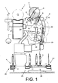
- Fig. 1 is a side view schematically a job 2 of a cheese-producing textile machine, in the embodiment, a so-called cross-winding machine 1, shown.
- the spinning rings 3 produced on ring spinning machines are rewound to large-volume cheeses 5 on the workstations 2 of such automatic winder 1.
- the cheeses 5 are after their completion by means of a (not shown) automatically operating service unit, preferably a cheese changer, handed over to a machine-length cheese package transport means 7 and transported to a machine end side Spulenverladestation or the like.
- a (not shown) automatically operating service unit preferably a cheese changer
- such automatic packages 1 also have a logistics device in the form of a package and tube transport system 6.
- the spinning cops 3 or empty tubes run on transport plates 11. From the sleeve transport system 6 are in the Fig. 1 only the Kopszu slaughterhouse 24, the reversibly driven storage section 25, one of the leading to the winding units 2 transverse transport sections 26 and the sleeve return path 27 shown.
- Each workstation 2 of the automatic winder 1 has a workstation computer 28, which is connected via a bus connection 29 to a central control unit 30 of the cheese-winder 1, as well as various other devices which are necessary for the proper operation of the workstations 2.
- Such a winding device 4 has a coil frame 8 which is movably mounted about a pivot axis 12.
- Fig. 1 indicated in the creel 8 freely rotatably supported cross-wound bobbin 5 during the winding operation with its surface on a support and drive roller 9, which is acted upon by an electric motor 33.
- the electric motor 33 is connected via a control line 35 to the workstation computer 28.
- Fadenchangier listening 10 For traversing the thread 16 during the winding process a Fadenchangier listening 10 is provided.
- Fadenchangier aggr 10 consists for example of a finger thread guide 13, which, acted upon by an electric motor drive 14, traversing the accumulating on the cheese 5 thread 16 between the end faces of the cheese 5 traversed.
- the thread guide drive 14 Via a control line 15, the thread guide drive 14 is in operative connection with the workstation computer 28.
- Such jobs 2 also have a thread connecting device 42, preferably a pneumatic splicing device, a gripper tube 43 for handling the lower thread and a suction nozzle 17 according to the invention, with which the accumulated on the cheese 5 and the upper thread can be inserted into the thread connecting device 42.
- a thread connecting device 42 preferably a pneumatic splicing device, a gripper tube 43 for handling the lower thread and a suction nozzle 17 according to the invention, with which the accumulated on the cheese 5 and the upper thread can be inserted into the thread connecting device 42.
- the suction nozzle 17 in this case has a flow-optimized suction nozzle head 18 whose specific shape is described below with reference to FIG Figures 2-4 is explained.
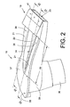
- the Fig. 2 shows a perspective view of the suction nozzle head 18 according to the invention, which consists essentially of a suction nozzle 39 and a Saugdüsdeckel 37, which are connected by bolts 38 or the like.
- the Saugdüsenfuß 39 has in its end region on a connecting piece 36 which is fixed in a pivot tube of the suction nozzle 17.
- the suction nozzle cover 37 has an inwardly directed profiling 34, which protrudes into the clear cross section of the suction nozzle 17 in such a way that lateral cross-sectional areas 21 and a central cross-sectional area 22 are formed in the region of the section 20 of the suction nozzle 17.
- air guide surfaces 40 are formed on the Saugdüsendeckel, which provide a defined air flow.
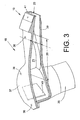
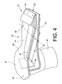
- the lateral cross-sectional areas 21 in the majority of the portion 20 to a height H which is in each case significantly above the height h of the adjacent central cross-sectional area 22.
- an inlet region 19 with an inlet opening 23 is arranged.
- the inlet opening 23 is thereby enclosed by a comb strip 41 which meshes with the swiveling back of the suction nozzle 17 any loops from the recorded thread 16.
Landscapes
- Engineering & Computer Science (AREA)
- Textile Engineering (AREA)
- Replacing, Conveying, And Pick-Finding For Filamentary Materials (AREA)
- Spinning Or Twisting Of Yarns (AREA)
- Coiling Of Filamentary Materials In General (AREA)
- Yarns And Mechanical Finishing Of Yarns Or Ropes (AREA)
- Treatment Of Fiber Materials (AREA)
Description
- Die Erfindung betrifft eine Saugdüse für eine Arbeitsstelle einer Kreuzspulen herstellenden Textilmaschine gemäß dem Oberbegriff des Anspruches 1.
- Im Zusammenhang mit dem Betrieb von Kreuzspulen herstellenden Textilmaschinen, insbesondere von Kreuzspulautomaten, ist es üblich, im Falle einer Spulunterbrechung, zum Beispiel bei einem Fadenbruch, bei einem kontrollierten Reinigerschnitt oder bei einem Vorlagespulenwechsel über einen Spulstellenrechner der betreffenden Spulstelle eine arbeitsstelleneigene Fadenverbindungsautomatik zu aktivieren.
- Das heißt, der Spulstellenrechner sorgt dafür, dass, wie beispielsweise in der
DE 40 05 752 A1 beschrieben, zunächst eine so genannte Saugdüse mit ihrer Mündung an die Oberfläche der langsam gegen die Wickelrichtung drehenden Auflaufspule angelegt und mit Unterdruck beaufschlagt wird. - Die Saugdüse versucht dabei, mit ihrer Mündung das Fadenende des Oberfadens von der Oberfläche der als Kreuzspule ausgebildeten Auflaufspule aufzunehmen.
- Nach dem Erfassen des Oberfadenendes schwenkt die Saugdüse in ihre Ausgangslage, in der die Mündung der Saugdüse unterhalb einer Fadenspleirsvorrichtung positioniert ist, zurück.
- Der sich zwischen der Kreuzspule und der Saugdüse erstreckende Fadenstrang wird dabei in einen oberhalb der Fadenverbindungsvorrichtung angeordneten elektronischen Reiniger, eine in diesem Bereich positionierte Klemm- und Schneideinrichtung sowie, durch entsprechende Leitkonturen von Fadenleitblechen und Fadenleitbügeln geführt, in die Schere einer unterhalb der Spleißvorrichtung befindlichen Schneideinrichtung eingezogen.
- Nahezu gleichzeitig mit der Saugdüse schwenkt ein in einer unteren Ausgangslage positioniertes Greiferrohr in eine obere Arbeitsstellung und bringt dabei einen bis dahin beispielsweise in einem Fadenspanner gehaltenen, von der Vorlagespule abgezogenen Unterfaden mit.
- Beim Einschwenken des Greiferrohres in seine obere Arbeitsstellung gleitet der Unterfaden, der ebenfalls an entsprechenden Fadenleitkonturen geführt ist, in eine geöffnete Fadenklemme sowie eine geöffnete Schneideinrichtung. Unter- und Oberfaden werden anschließend auf die richtige Länge abgeschnitten, in so genannten Auflöseröhrchen vorbereitet und in der Fadenspleißeinrichtung miteinander verbunden.
- Das bedeutet, an den Arbeitsstellen eines Kreuzspulautomaten werden, um, zum Beispiel nach einem Fadenbruch, den Betrieb automatisch fortführen zu können, stets sowohl ein von der Kreuzspule zurückgeholter Oberfaden als auch ein von der Vorlagespule kommender Unterfaden benötigt.
- Die vorbeschriebenen Fadenverbindungsautomatiken haben sich in der Praxis bewährt und sind in der Textilindustrie seit langer Zeit in großer Stückzahl im Einsatz.
- Bei diesen bekannten Einrichtungen treten allerdings gelegentlich Schwierigkeiten bei der Aufnahme des Oberfadenendes von der Oberfläche der Auflaufspule auf.
- Diese Schwierigkeiten ergeben sich insbesondere dann, wenn das auf die Kreuzspule aufgelaufene Fadenende weit am Rande der Kreuzspule aufgelaufen ist und dabei eventuell auch noch relativ stark eingewalkt wurde.
- In solchen Fällen ist die Saugkraft der bekannten Saugdüsen, besonders in den Randbereichen ihrer relativ breiten Mündung, oftmals nicht ausreichend, um das Fadenende des Oberfadens sicher von der Oberfläche der Auflaufspule aufzunehmen.
- Ausgehend vom vorgenannten Stand der Technik liegt der Erfindung die Aufgabe zugrunde, eine Saugdüse zu entwickeln, die so ausgebildet ist, dass ein auf die Kreuzspule aufgelaufenes Fadenende eines Oberfadens sicherer gehandhabt werden kann.
- Das heißt, dass ein Fadenende auch dann noch zuverlässig aufgenommen werden kann, wenn das Fadenende im Randbereich der Auflaufspule aufgelaufen und eventuell eingewalkt ist.
- Diese Aufgabe wird erfindungsgemäß durch eine Saugdüse gelöst, wie sie im Anspruch 1 beschrieben ist.
- Vorteilhafte Ausgestaltungen der erfindungsgemäßen Saugdüse sind Gegenstand der Unteransprüche.
- Die erfindungsgemäße Saugdüse hat den Vorteil, dass der innerhalb der Saugdüse wirksame Saugluftstrom, insbesondere auch im Bereich der Eingangsöffnung, verstärkt auf die seitlichen Randbereiche der Eingangsöffnung der Saugdüse konzentriert und damit in den Problemzonen der Auflaufspule intensiver wirksam wird.
- Das heißt, durch die Profilierung wird dieser Abschnitt der Saugdüse in zwei seitliche Querschnittsbereiche und einen dazwischen angeordneten, mittleren Querschnittsbereich aufgeteilt, wobei der Luftdurchsatz im Bereich der seitlichen Querschnittsbereiche, nicht zuletzt aufgrund ihrer in weiten Bereichen größeren Höhe, über dem Luftdurchsatz des mittleren Querschnittsbereiches liegt.
- Wie im Anspruch 2 dargelegt, ist die Profilierung vorzugsweise Bestandteil eines Saugdüsendeckels, der, beispielsweise über Schraubenbolzen, mit einem Saugdüsenfuß verbunden ist.
- Eine solche Ausführungsform lässt sich durch Spritz- oder Druckgussteile kostengünstig realisieren.
- Das heißt, diese in entsprechenden Urformwerkzeugen gefertigten Bauteile können mittels z. B. Schraubenbolzen oder dgl. schnell und problemlos zu einer erfindungsgemäßen Saugdüse zusammengefügt werden.
- Entsprechende Versuche haben ergeben, dass eine besonders vorteilhafte Ausführungsform der Saugdüse gegeben ist, wenn, wie im Anspruch 3 dargelegt, die Höhe der seitlichen Querschnittsbereiche und die Höhe des mittleren Querschnittsbereiches mit wachsendem Abstand zum Eingangsbereich der Saugdüse größer wird.
- Auf diese Weise erhält man im Bereich der Eingangsöffnung insgesamt eine relativ starke Saugwirkung, durch die das Fadenende aufgenommen wird, während der in die Saugdüse eingesaugte Faden innerhalb der Saugdüse relativ schonend behandelt wird.
- Gemäß Anspruch 4 weist die Saugdüse in ihrem endseitigen Bereich Luftführungsflächen auf, die vorteilhafterweise einstückig an den Saugdüsendeckel angeformt sind.
- Durch solche Luftführungsflächen lässt sich auf einfache Weise eine definierte Saugluftströmung in der Saugdüse erzielen.
- Das heißt, Luftverwirbelungen, die auch den aufgenommenen Faden negativ beeinflussen würden, werden weitestgehend vermieden.
- Durch die im Anspruch 5 beschriebene Ausbildung der Saugdüse, bei der der Saugdüsenkopf im Bereich der Eingangöffnung mit einer Kammleiste ausgestattet ist, wird die Güte der Arbeitsleistung der Saugdüse bei der Fadenendaufnahme weiter verbessert.
- Die Kammleiste sorgt beispielsweise beim Zurückschwenken der Saugdüse dafür, dass zum Beispiel Schlaufen, die eventuell im aufgenommenen Faden vorhanden sind, ausgekämmt werden, so dass beim anschließenden Fadenverbindungsvorgang stets nur ein Einzelfaden vorliegt.
- Die Erfindung wird nachfolgend anhand eines in den Zeichnungen dargestellten Ausführungsbeispieles erläutert.
- Es zeigen:
- Fig. 1
- schematisch eine Spulstelle einer Kreuzspulen herstellenden Textilmaschine mit einer erfindungsgemäßen Saugdüse,
- Fig. 2
- eine perspektivische Ansicht des Saugdüsenkopfes einer erfindungsgemäßen Saugdüse,
- Fig. 3
- den Saugdüsenkopf gemäß Schnitt III-III in der
Fig.2 , - Fig. 4
- den Saugdüsenkopf gemäß Schnitt IV-IV in der
Fig.2 . - In
Fig. 1 ist in Seitenansicht schematisch eine Arbeitsstelle 2 einer Kreuzspulen herstellenden Textilmaschine, im Ausführungsbeispiel ein so genannter Kreuzspulautomaten 1, dargestellt. - Auf den Arbeitsstellen 2 derartiger Kreuzspulautomaten 1 werden, wie bekannt und daher nicht näher erläutert, die auf Ringspinnmaschinen produzierten Spinnkopse 3 zu großvolumigen Kreuzspulen 5 umgespult.
- Die Kreuzspulen 5 werden nach ihrer Fertigstellung mittels eines (nicht dargestellten) selbsttätig arbeitenden Serviceaggregates, vorzugsweise eines Kreuzspulenwechslers, auf eine maschinenlange Kreuzspulentransporteinrichtung 7 übergeben und zu einer maschinenendseitig angeordneten Spulenverladestation oder dergleichen transportiert.
- Solche Kreuzspulautomaten 1 weisen in der Regel außerdem eine Logistikeinrichtung in Form eines Spulen- und Hülsentransportsystems 6 auf. In diesem Spulen- und Hülsentransportsystem 6 laufen die Spinnkopse 3 beziehungsweise Leerhülsen auf Transporttellern 11 um. Vom Hülsentransportsystem 6 sind in der
Fig. 1 lediglich die Kopszuführstrecke 24, die reversierend antreibbare Speicherstrecke 25, eine der zu den Spulstellen 2 führenden Quertransportstrecken 26 sowie die Hülsenrückführstrecke 27 dargestellt. - Jede Arbeitsstelle 2 des Kreuzspulautomaten 1 weist einen Arbeitsstellenrechner 28, der über eine Busverbindung 29 an eine zentrale Steuereinheit 30 des Kreuzspulautomaten 1 angeschlossen ist, sowie verschiedene weitere Einrichtungen auf, die für einen ordnungsgemäßen Betrieb der Arbeitsstellen 2 notwendig sind.
- Eine dieser an sich bekannten Einrichtungen ist beispielsweise die Spulvorrichtung 4. Eine solche Spulvorrichtung 4 verfügt über einen Spulenrahmen 8, der um eine Schwenkachse 12 beweglich gelagert ist.
- Wie in
Fig. 1 angedeutet, liegt die im Spulenrahmen 8 frei rotierbar gehalterte Kreuzspule 5 während des Spulbetriebes mit ihrer Oberfläche auf einer Stütz- und Antriebswalze 9 auf, die durch einen Elektromotor 33 beaufschlagt wird. Der Elektromotor 33 ist dabei über eine Steuerleitung 35 an den Arbeitsstellenrechner 28 angeschlossen. - Zur Changierung des Fadens 16 während des Spulprozesses ist eine Fadenchangiereinrichtung 10 vorgesehen. Eine solche, in der
Fig. 1 lediglich schematisch angedeutete Fadenchangiereinrichtung 10 besteht beispielsweise aus einem Fingerfadenführer 13, der, durch einen elektromotorischen Antrieb 14 beaufschlagt, den auf die Kreuzspule 5 auflaufenden Faden 16 zwischen den Stirnseiten der Kreuzspule 5 traversiert. Über eine Steuerleitung 15 steht der Fadenführerantrieb 14 dabei mit dem Arbeitsstellenrechner 28 in Wirkverbindung. - Solche Arbeitsstellen 2 verfügen außerdem über eine Fadenverbindungseinrichtung 42, vorzugsweise eine pneumatische Spleißeinrichtung, ein Greiferrohr 43 zum Handhaben des Unterfadens sowie über eine erfindungsgemäße Saugdüse 17, mit der der auf die Kreuzspule 5 aufgelaufenen Oberfaden aufgenommen und in die Fadenverbindungseinrichtung 42 eingelegt werden kann.
- Die Saugdüse 17 weist dabei einen strömungsoptimierten Saugdüsenkopf 18 auf, dessen spezielle Form nachfolgend anhand der
Figuren 2 - 4 erläutert wird. - Die
Fig. 2 zeigt eine perspektivische Ansicht des erfindungsgemäßen Saugdüsenkopfes 18, der im Wesentlichen aus einem Saugdüsenfuß 39 sowie einem Saugdüsendeckel 37 besteht, die über Schraubenbolzen 38 oder dgl. verbunden sind. - Der Saugdüsenfuß 39 weist in seinem endseitigen Bereich einen Anschlussstutzen 36 auf, der in einem Schwenkrohr der Saugdüse 17 festgelegt ist.
- Der Saugdüsendeckel 37 verfügt über eine nach innen gerichtete Profilierung 34, die so in den lichten Querschnitt der Saugdüse 17 ragt, dass im Bereich des Abschnittes 20 der Saugdüse 17 seitliche Querschnittsbereiche 21 und ein mittlerer Querschnittsbereich 22 entstehen.
- Endseitig sind an den Saugdüsendeckel 37 Luftleitflächen 40 angeformt, die für eine definierte Luftführung sorgen.
- Wie in den
Figuren 3 und4 angedeutet, weisen die seitlichen Querschnittsbereiche 21 im überwiegenden Teil des Abschnitts 20 eine Höhe H auf, die jeweils deutlich über der Höhe h des benachbarten mittleren Querschnittsbereichs 22 liegt. - Vor dem Abschnitt 20 der Saugdüse 17 ist ein Eingangsbereich 19 mit einer Eingangsöffnung 23 angeordnet.
- Die Eingangsöffnung 23 wird dabei von einer Kammleiste 41 umschlossen, die beim Zurückschwenken der Saugdüse 17 eventuelle Schlaufen aus dem aufgenommenen Faden 16 kämmt.
Claims (5)
- Saugdüse (17) für eine Arbeitsstelle (2) einer Kreuzspulen (5) herstellenden Textilmaschine (1), die mit Unterdruck beaufschlagbar und so schwenkbar gelagert ist, dass eine Eingangsöffnung am Saugdüsenkopf (18) der Saugdüse (17) zum Aufnehmen eines auf die Kreuzspule (5) aufgelaufenen Fadenendes im Bereich der Oberfläche der in einem Spulenrahmen (8) drehbar gehalterten Kreuzspule (5) positionierbar ist,
dadurch gekennzeichnet,
dass sich an einen vorderen Eingangsbereich (19), der die Eingangsöffnung (23) aufweist, ein Abschnitt (20) des Saugdüsenkopfes (18) anschließt, der über eine in den lichten Querschnitt des Abschnittes (20) ragende Profilierung (34) verfügt,
dass die Profilierung (34) den Abschnitt (20) in zwei seitliche Querschnittsbereiche (21) und einen dazwischen angeordneten, mittleren Querschnittsbereich (22) aufteilt und dass die seitlichen Querschnittsbereiche (21) im überwiegenden Teil des Abschnittes (20) eine Höhe (H) aufweisen, die jeweils deutlich über der Höhe (h) des benachbarten mittleren Querschnittsbereiches (22) liegt. - Saugdüse nach Anspruch 1, dadurch gekennzeichnet, dass die Profilierung (34) Bestandteil eines Saugdüsendeckels (37) ist, der, beispielsweise über Schraubenbolzen (38), mit einem Saugdüsenfuß (39) verbunden ist.
- Saugdüse nach Anspruch 1 und 2, dadurch gekennzeichnet, dass die Höhe (H) der seitlichen Querschnittsbereiche (21) und die Höhe (h) des mittleren Querschnittsbereiches (22) mit wachsendem Abstand zum Eingangsbereich (19) größer werden.
- Saugdüse nach Anspruch 2, dadurch gekennzeichnet, dass der Saugdüsendeckel (37) in seinem endseitigen Bereich Luftführungsflächen (40) aufweist.
- Saugdüse nach Anspruch 1 und 2, dadurch gekennzeichnet, dass der Saugdüsenkopf (18) im Bereich der Eingangöffnung (23) mit einer Kammleiste (41) ausgestattet ist.
Applications Claiming Priority (2)
| Application Number | Priority Date | Filing Date | Title |
|---|---|---|---|
| DE102006039735A DE102006039735A1 (de) | 2006-08-24 | 2006-08-24 | Saugdüse für eine Arbeitsstelle einer Kreuzspulen herstellenden Textilmaschine |
| PCT/EP2007/006412 WO2008022676A1 (de) | 2006-08-24 | 2007-07-19 | Saugdüse für eine arbeitsstelle einer kreuzspulen herstellenden textilmaschine |
Publications (2)
| Publication Number | Publication Date |
|---|---|
| EP2066577A1 EP2066577A1 (de) | 2009-06-10 |
| EP2066577B1 true EP2066577B1 (de) | 2010-01-06 |
Family
ID=38584142
Family Applications (1)
| Application Number | Title | Priority Date | Filing Date |
|---|---|---|---|
| EP07786184A Not-in-force EP2066577B1 (de) | 2006-08-24 | 2007-07-19 | Saugdüse für eine arbeitsstelle einer kreuzspulen herstellenden textilmaschine |
Country Status (5)
| Country | Link |
|---|---|
| EP (1) | EP2066577B1 (de) |
| CN (1) | CN101506075B (de) |
| AT (1) | ATE454349T1 (de) |
| DE (2) | DE102006039735A1 (de) |
| WO (1) | WO2008022676A1 (de) |
Families Citing this family (9)
| Publication number | Priority date | Publication date | Assignee | Title |
|---|---|---|---|---|
| DE102008026777A1 (de) * | 2008-06-04 | 2009-12-10 | Oerlikon Textile Gmbh & Co. Kg | Saugdüse |
| DE102010049435A1 (de) * | 2010-10-23 | 2012-04-26 | Oerlikon Textile Gmbh & Co. Kg | Arbeitsstelle einer Spulmaschine |
| DE102011114765A1 (de) | 2011-10-01 | 2013-04-04 | Oerlikon Textile Gmbh & Co. Kg | Kammleiste für eine Saugdüse einer Arbeitsstelle einer Kreuzspulen herstellenden Textilmaschine |
| DE102011114769A1 (de) | 2011-10-01 | 2013-04-04 | Oerlikon Textile Gmbh & Co. Kg | Saugdüse für eine Arbeitsstelle einer Kreuzspulen herstellenden Textilmaschine |
| DE102013011664A1 (de) * | 2013-07-11 | 2015-01-15 | Saurer Germany Gmbh & Co. Kg | Arbeitsstelle einer Kreuzspulen herstellenden Textilmaschine |
| CN104555602B (zh) * | 2013-10-09 | 2017-07-11 | 江苏凯宫机械股份有限公司 | 结构优化的筒纱吸附辅助系统 |
| JP2015157669A (ja) * | 2014-02-24 | 2015-09-03 | 村田機械株式会社 | 糸端捕捉装置、及び、糸巻取装置 |
| DE102015005392A1 (de) * | 2015-04-28 | 2016-11-03 | Saurer Germany Gmbh & Co. Kg | Arbeitsstelle einer Auflaufspulen herstellenden Textilmaschine |
| DE102015005393A1 (de) * | 2015-04-28 | 2016-11-03 | Saurer Germany Gmbh & Co. Kg | Arbeitsstelle einer Auflaufspulen herstellenden Textilmaschine |
Family Cites Families (12)
| Publication number | Priority date | Publication date | Assignee | Title |
|---|---|---|---|---|
| US2857113A (en) * | 1953-11-03 | 1958-10-21 | Reiners Walter Dr Ing | Suction nozzle for catching thread ends |
| DE960618C (de) * | 1953-11-03 | 1957-03-21 | Reiners Walter Dr Ing | Saugduese an Spulmaschinen zum Erfassen, Aufsuchen, Abheben od. dgl. von Fadenenden |
| DE1147156B (de) * | 1959-05-15 | 1963-04-11 | Schweiter Ag Maschf | Saugduese zum Aufsuchen und Erfassen von Fadenenden an einer Spulmaschine |
| CH651812A5 (de) * | 1981-07-24 | 1985-10-15 | Schweiter Ag Maschf | Vorrichtung zum abziehen von garnenden an textilspulen. |
| IT1229739B (it) * | 1989-05-16 | 1991-09-07 | Savio Spa | Procedimento per la realizzazione di pettini da applicare a bocchette aspiranti per la captazione del bandolo di filati avvolti in confezione e pettini perfezionati cosi' ottenuti. |
| DE4004028C2 (de) * | 1990-02-10 | 2001-06-07 | Schlafhorst & Co W | Verfahren und Vorrichtung zum Bilden einer Fadenreserve auf einer Kreuzspule |
| DE4005752C2 (de) * | 1990-02-23 | 1998-10-08 | Schlafhorst & Co W | Verfahren und Vorrichtung zum Vorbereiten zu spleißender Fadenenden |
| DE19650933A1 (de) * | 1996-12-07 | 1998-06-10 | Schlafhorst & Co W | Spulaggregat einer Kreuzspulen herstellenden Textilmaschine |
| DE19955396A1 (de) * | 1999-11-18 | 2001-05-23 | Rieter Ag Maschf | Spinnmaschine mit Absaugrohr an Verdichtungseinrichtung |
| DE10139074B4 (de) * | 2001-08-09 | 2009-11-12 | Oerlikon Textile Gmbh & Co. Kg | Offenend-Rotorspinnmaschine |
| DE10206288A1 (de) * | 2002-02-15 | 2003-08-28 | Schlafhorst & Co W | Verfahren und Vorrichtung zum Betreiben einer Arbeitsstelle einer Kreuzspulen herstellenden Textilmaschine |
| DE102005014887A1 (de) * | 2005-04-01 | 2006-10-05 | Saurer Gmbh & Co. Kg | Kreuzspulen herstellende Textilmaschine |
-
2006
- 2006-08-24 DE DE102006039735A patent/DE102006039735A1/de not_active Withdrawn
-
2007
- 2007-07-19 EP EP07786184A patent/EP2066577B1/de not_active Not-in-force
- 2007-07-19 CN CN2007800305192A patent/CN101506075B/zh active Active
- 2007-07-19 DE DE502007002586T patent/DE502007002586D1/de active Active
- 2007-07-19 AT AT07786184T patent/ATE454349T1/de active
- 2007-07-19 WO PCT/EP2007/006412 patent/WO2008022676A1/de not_active Ceased
Also Published As
| Publication number | Publication date |
|---|---|
| CN101506075A (zh) | 2009-08-12 |
| ATE454349T1 (de) | 2010-01-15 |
| EP2066577A1 (de) | 2009-06-10 |
| DE502007002586D1 (de) | 2010-02-25 |
| DE102006039735A1 (de) | 2008-02-28 |
| WO2008022676A1 (de) | 2008-02-28 |
| CN101506075B (zh) | 2012-04-25 |
Similar Documents
| Publication | Publication Date | Title |
|---|---|---|
| EP2066577A1 (de) | Saugdüse für eine arbeitsstelle einer kreuzspulen herstellenden textilmaschine | |
| EP2957532B1 (de) | Arbeitsstelle einer kreuzspulen herstellenden textilmaschine | |
| DE102009024037A1 (de) | Verfahren zur Behebung einer Fadenunterbrechung an einer Arbeitsstelle einer Spulmaschine und Arbeitsstelle einer Spulmaschine | |
| DE102008026777A1 (de) | Saugdüse | |
| DE102016119542A1 (de) | Fadenspleißvorrichtung für eine Arbeitsstelle einer Kreuzspulen herstellenden Textilmaschine | |
| DE102012016853A1 (de) | Verfahren zum Verbinden eines Ober- und Unterfadens an einer Arbeitsstelle einer Spulmaschine und Arbeitsstelle einer Spulmaschine | |
| DE102009009971A1 (de) | Verfahren und Vorrichtung zum Betreiben einer Arbeitsstelle einer Kreuzspulen herstellenden Textilmaschine sowie Arbeitsstelle zur Durchführung des Verfahrens | |
| DE102012016854A1 (de) | Verfahren zum Verbinden eines Ober- und Unterfadens an einer Arbeitsstelle einer Spulmaschine und Arbeitsstelle einer Spulmaschine | |
| EP1076028B1 (de) | Fadenverbindungseinrichtung für eine Kreuzspulen herstellende Textilmaschine | |
| EP2388224A2 (de) | Bedienaggregat | |
| DE102018120457A1 (de) | Fadenspleißvorrichtung für eine Arbeitsstelle einer Kreuzspulen herstellenden Textilmaschine | |
| CH714064B1 (de) | Vorrichtung zur Ausreinigung von Garnfehlern aus einem Garn. | |
| EP1127831B1 (de) | Vorrichtung zur Inbetriebnahme einer Arbeitsstelle einer Kreuzspule herstellenden Textilmaschine | |
| DE10150590A1 (de) | Arbeitsstelle einer Kreuzspulen herstellenden Textilmaschine | |
| EP2824054B1 (de) | Arbeitsstelle einer Kreuzspulen herstellenden Textilmaschine | |
| DE102009033377A1 (de) | Verfahren und Vorrichtung zum Betreiben einer Arbeitsstelle einer Kreuzspulen herstellenden Textilmaschine | |
| EP2574581B1 (de) | Saugdüse für eine Arbeitsstelle einer Kreuzspulen herstellenden Textilmaschine | |
| DE102018108151A1 (de) | Fadenspleißvorrichtung für eine Arbeitsstelle einer Kreuzspulen herstellenden Textilmaschine | |
| DE102017102438A1 (de) | Fadenspleißvorrichtung für eine Arbeitsstelle einer Kreuzspulen herstellenden Textilmaschine | |
| EP2574580B1 (de) | Kammleiste für eine Saugdüse einer Arbeitsstelle einer Kreuzspulen herstellenden Textilmaschine | |
| DE102017129580A1 (de) | Rotationsspleißer für eine Arbeitsstelle auf einer Kreuzspulen herstellenden Textilmaschine | |
| EP1917204B1 (de) | Spulstelle einer kreuzspule herstellenden textilmaschine | |
| DE102012002986A1 (de) | Arbeitsstelle einer Kreuzspulen herstellenden Textilmaschine | |
| DE102010049435A1 (de) | Arbeitsstelle einer Spulmaschine | |
| EP2987756B1 (de) | Arbeitsstelle einer kreuzspulen herstellenden textilmaschine |
Legal Events
| Date | Code | Title | Description |
|---|---|---|---|
| PUAI | Public reference made under article 153(3) epc to a published international application that has entered the european phase |
Free format text: ORIGINAL CODE: 0009012 |
|
| 17P | Request for examination filed |
Effective date: 20090324 |
|
| AK | Designated contracting states |
Kind code of ref document: A1 Designated state(s): AT BE BG CH CY CZ DE DK EE ES FI FR GB GR HU IE IS IT LI LT LU LV MC MT NL PL PT RO SE SI SK TR |
|
| AX | Request for extension of the european patent |
Extension state: AL BA HR MK RS |
|
| GRAP | Despatch of communication of intention to grant a patent |
Free format text: ORIGINAL CODE: EPIDOSNIGR1 |
|
| GRAS | Grant fee paid |
Free format text: ORIGINAL CODE: EPIDOSNIGR3 |
|
| GRAA | (expected) grant |
Free format text: ORIGINAL CODE: 0009210 |
|
| AK | Designated contracting states |
Kind code of ref document: B1 Designated state(s): AT BE BG CH CY CZ DE DK EE ES FI FR GB GR HU IE IS IT LI LT LU LV MC MT NL PL PT RO SE SI SK TR |
|
| REG | Reference to a national code |
Ref country code: GB Ref legal event code: FG4D Free format text: NOT ENGLISH |
|
| REG | Reference to a national code |
Ref country code: CH Ref legal event code: EP |
|
| REG | Reference to a national code |
Ref country code: IE Ref legal event code: FG4D |
|
| REF | Corresponds to: |
Ref document number: 502007002586 Country of ref document: DE Date of ref document: 20100225 Kind code of ref document: P |
|
| REG | Reference to a national code |
Ref country code: NL Ref legal event code: VDEP Effective date: 20100106 |
|
| PG25 | Lapsed in a contracting state [announced via postgrant information from national office to epo] |
Ref country code: SI Free format text: LAPSE BECAUSE OF FAILURE TO SUBMIT A TRANSLATION OF THE DESCRIPTION OR TO PAY THE FEE WITHIN THE PRESCRIBED TIME-LIMIT Effective date: 20100106 |
|
| LTIE | Lt: invalidation of european patent or patent extension |
Effective date: 20100106 |
|
| PG25 | Lapsed in a contracting state [announced via postgrant information from national office to epo] |
Ref country code: PT Free format text: LAPSE BECAUSE OF FAILURE TO SUBMIT A TRANSLATION OF THE DESCRIPTION OR TO PAY THE FEE WITHIN THE PRESCRIBED TIME-LIMIT Effective date: 20100506 Ref country code: LT Free format text: LAPSE BECAUSE OF FAILURE TO SUBMIT A TRANSLATION OF THE DESCRIPTION OR TO PAY THE FEE WITHIN THE PRESCRIBED TIME-LIMIT Effective date: 20100106 Ref country code: NL Free format text: LAPSE BECAUSE OF FAILURE TO SUBMIT A TRANSLATION OF THE DESCRIPTION OR TO PAY THE FEE WITHIN THE PRESCRIBED TIME-LIMIT Effective date: 20100106 Ref country code: ES Free format text: LAPSE BECAUSE OF FAILURE TO SUBMIT A TRANSLATION OF THE DESCRIPTION OR TO PAY THE FEE WITHIN THE PRESCRIBED TIME-LIMIT Effective date: 20100417 Ref country code: IS Free format text: LAPSE BECAUSE OF FAILURE TO SUBMIT A TRANSLATION OF THE DESCRIPTION OR TO PAY THE FEE WITHIN THE PRESCRIBED TIME-LIMIT Effective date: 20100506 |
|
| REG | Reference to a national code |
Ref country code: IE Ref legal event code: FD4D |
|
| PG25 | Lapsed in a contracting state [announced via postgrant information from national office to epo] |
Ref country code: LV Free format text: LAPSE BECAUSE OF FAILURE TO SUBMIT A TRANSLATION OF THE DESCRIPTION OR TO PAY THE FEE WITHIN THE PRESCRIBED TIME-LIMIT Effective date: 20100106 Ref country code: PL Free format text: LAPSE BECAUSE OF FAILURE TO SUBMIT A TRANSLATION OF THE DESCRIPTION OR TO PAY THE FEE WITHIN THE PRESCRIBED TIME-LIMIT Effective date: 20100106 Ref country code: FI Free format text: LAPSE BECAUSE OF FAILURE TO SUBMIT A TRANSLATION OF THE DESCRIPTION OR TO PAY THE FEE WITHIN THE PRESCRIBED TIME-LIMIT Effective date: 20100106 |
|
| PG25 | Lapsed in a contracting state [announced via postgrant information from national office to epo] |
Ref country code: IE Free format text: LAPSE BECAUSE OF FAILURE TO SUBMIT A TRANSLATION OF THE DESCRIPTION OR TO PAY THE FEE WITHIN THE PRESCRIBED TIME-LIMIT Effective date: 20100106 Ref country code: GR Free format text: LAPSE BECAUSE OF FAILURE TO SUBMIT A TRANSLATION OF THE DESCRIPTION OR TO PAY THE FEE WITHIN THE PRESCRIBED TIME-LIMIT Effective date: 20100407 Ref country code: RO Free format text: LAPSE BECAUSE OF FAILURE TO SUBMIT A TRANSLATION OF THE DESCRIPTION OR TO PAY THE FEE WITHIN THE PRESCRIBED TIME-LIMIT Effective date: 20100106 Ref country code: SE Free format text: LAPSE BECAUSE OF FAILURE TO SUBMIT A TRANSLATION OF THE DESCRIPTION OR TO PAY THE FEE WITHIN THE PRESCRIBED TIME-LIMIT Effective date: 20100106 Ref country code: CY Free format text: LAPSE BECAUSE OF FAILURE TO SUBMIT A TRANSLATION OF THE DESCRIPTION OR TO PAY THE FEE WITHIN THE PRESCRIBED TIME-LIMIT Effective date: 20100106 Ref country code: EE Free format text: LAPSE BECAUSE OF FAILURE TO SUBMIT A TRANSLATION OF THE DESCRIPTION OR TO PAY THE FEE WITHIN THE PRESCRIBED TIME-LIMIT Effective date: 20100106 |
|
| PLBE | No opposition filed within time limit |
Free format text: ORIGINAL CODE: 0009261 |
|
| STAA | Information on the status of an ep patent application or granted ep patent |
Free format text: STATUS: NO OPPOSITION FILED WITHIN TIME LIMIT |
|
| PG25 | Lapsed in a contracting state [announced via postgrant information from national office to epo] |
Ref country code: BG Free format text: LAPSE BECAUSE OF FAILURE TO SUBMIT A TRANSLATION OF THE DESCRIPTION OR TO PAY THE FEE WITHIN THE PRESCRIBED TIME-LIMIT Effective date: 20100406 Ref country code: SK Free format text: LAPSE BECAUSE OF FAILURE TO SUBMIT A TRANSLATION OF THE DESCRIPTION OR TO PAY THE FEE WITHIN THE PRESCRIBED TIME-LIMIT Effective date: 20100106 Ref country code: CZ Free format text: LAPSE BECAUSE OF FAILURE TO SUBMIT A TRANSLATION OF THE DESCRIPTION OR TO PAY THE FEE WITHIN THE PRESCRIBED TIME-LIMIT Effective date: 20100106 |
|
| 26N | No opposition filed |
Effective date: 20101007 |
|
| BERE | Be: lapsed |
Owner name: OERLIKON TEXTILE G.M.B.H. & CO. KG Effective date: 20100731 |
|
| PG25 | Lapsed in a contracting state [announced via postgrant information from national office to epo] |
Ref country code: DK Free format text: LAPSE BECAUSE OF FAILURE TO SUBMIT A TRANSLATION OF THE DESCRIPTION OR TO PAY THE FEE WITHIN THE PRESCRIBED TIME-LIMIT Effective date: 20100106 |
|
| PG25 | Lapsed in a contracting state [announced via postgrant information from national office to epo] |
Ref country code: MC Free format text: LAPSE BECAUSE OF NON-PAYMENT OF DUE FEES Effective date: 20100731 |
|
| REG | Reference to a national code |
Ref country code: FR Ref legal event code: ST Effective date: 20110331 |
|
| PG25 | Lapsed in a contracting state [announced via postgrant information from national office to epo] |
Ref country code: FR Free format text: LAPSE BECAUSE OF NON-PAYMENT OF DUE FEES Effective date: 20100802 |
|
| PG25 | Lapsed in a contracting state [announced via postgrant information from national office to epo] |
Ref country code: BE Free format text: LAPSE BECAUSE OF NON-PAYMENT OF DUE FEES Effective date: 20100731 |
|
| PG25 | Lapsed in a contracting state [announced via postgrant information from national office to epo] |
Ref country code: MT Free format text: LAPSE BECAUSE OF FAILURE TO SUBMIT A TRANSLATION OF THE DESCRIPTION OR TO PAY THE FEE WITHIN THE PRESCRIBED TIME-LIMIT Effective date: 20100106 |
|
| REG | Reference to a national code |
Ref country code: CH Ref legal event code: PL |
|
| GBPC | Gb: european patent ceased through non-payment of renewal fee |
Effective date: 20110719 |
|
| PG25 | Lapsed in a contracting state [announced via postgrant information from national office to epo] |
Ref country code: LI Free format text: LAPSE BECAUSE OF NON-PAYMENT OF DUE FEES Effective date: 20110731 Ref country code: CH Free format text: LAPSE BECAUSE OF NON-PAYMENT OF DUE FEES Effective date: 20110731 |
|
| PG25 | Lapsed in a contracting state [announced via postgrant information from national office to epo] |
Ref country code: GB Free format text: LAPSE BECAUSE OF NON-PAYMENT OF DUE FEES Effective date: 20110719 |
|
| PG25 | Lapsed in a contracting state [announced via postgrant information from national office to epo] |
Ref country code: HU Free format text: LAPSE BECAUSE OF FAILURE TO SUBMIT A TRANSLATION OF THE DESCRIPTION OR TO PAY THE FEE WITHIN THE PRESCRIBED TIME-LIMIT Effective date: 20100707 Ref country code: LU Free format text: LAPSE BECAUSE OF NON-PAYMENT OF DUE FEES Effective date: 20100719 |
|
| REG | Reference to a national code |
Ref country code: AT Ref legal event code: MM01 Ref document number: 454349 Country of ref document: AT Kind code of ref document: T Effective date: 20120731 |
|
| PG25 | Lapsed in a contracting state [announced via postgrant information from national office to epo] |
Ref country code: AT Free format text: LAPSE BECAUSE OF NON-PAYMENT OF DUE FEES Effective date: 20120731 |
|
| REG | Reference to a national code |
Ref country code: DE Ref legal event code: R081 Ref document number: 502007002586 Country of ref document: DE Owner name: SAURER GERMANY GMBH & CO. KG, DE Free format text: FORMER OWNER: OERLIKON TEXTILE GMBH & CO. KG, 42897 REMSCHEID, DE Effective date: 20130918 Ref country code: DE Ref legal event code: R081 Ref document number: 502007002586 Country of ref document: DE Owner name: SAURER SPINNING SOLUTIONS GMBH & CO. KG, DE Free format text: FORMER OWNER: OERLIKON TEXTILE GMBH & CO. KG, 42897 REMSCHEID, DE Effective date: 20130918 |
|
| PGFP | Annual fee paid to national office [announced via postgrant information from national office to epo] |
Ref country code: TR Payment date: 20130718 Year of fee payment: 7 |
|
| PG25 | Lapsed in a contracting state [announced via postgrant information from national office to epo] |
Ref country code: TR Free format text: LAPSE BECAUSE OF NON-PAYMENT OF DUE FEES Effective date: 20140719 |
|
| REG | Reference to a national code |
Ref country code: DE Ref legal event code: R081 Ref document number: 502007002586 Country of ref document: DE Owner name: SAURER SPINNING SOLUTIONS GMBH & CO. KG, DE Free format text: FORMER OWNER: SAURER GERMANY GMBH & CO. KG, 42897 REMSCHEID, DE |
|
| PGFP | Annual fee paid to national office [announced via postgrant information from national office to epo] |
Ref country code: NL Payment date: 20180821 Year of fee payment: 6 |
|
| PGFP | Annual fee paid to national office [announced via postgrant information from national office to epo] |
Ref country code: IT Payment date: 20190731 Year of fee payment: 13 |
|
| REG | Reference to a national code |
Ref country code: DE Ref legal event code: R119 Ref document number: 502007002586 Country of ref document: DE |
|
| PG25 | Lapsed in a contracting state [announced via postgrant information from national office to epo] |
Ref country code: DE Free format text: LAPSE BECAUSE OF NON-PAYMENT OF DUE FEES Effective date: 20200201 |
|
| PG25 | Lapsed in a contracting state [announced via postgrant information from national office to epo] |
Ref country code: IT Free format text: LAPSE BECAUSE OF NON-PAYMENT OF DUE FEES Effective date: 20200719 |