EP2065575B1 - Wall-flow honeycomb filter having high-storage capacity and low backpressure - Google Patents
Wall-flow honeycomb filter having high-storage capacity and low backpressure Download PDFInfo
- Publication number
- EP2065575B1 EP2065575B1 EP07301601A EP07301601A EP2065575B1 EP 2065575 B1 EP2065575 B1 EP 2065575B1 EP 07301601 A EP07301601 A EP 07301601A EP 07301601 A EP07301601 A EP 07301601A EP 2065575 B1 EP2065575 B1 EP 2065575B1
- Authority
- EP
- European Patent Office
- Prior art keywords
- inlet
- cells
- walls
- wall
- filter
- Prior art date
- Legal status (The legal status is an assumption and is not a legal conclusion. Google has not performed a legal analysis and makes no representation as to the accuracy of the status listed.)
- Active
Links
- 238000003860 storage Methods 0.000 title description 5
- 210000004027 cell Anatomy 0.000 claims description 256
- 230000003197 catalytic effect Effects 0.000 claims description 19
- 238000000034 method Methods 0.000 claims description 16
- 238000011068 loading method Methods 0.000 claims description 15
- 239000002002 slurry Substances 0.000 claims description 10
- 210000002421 cell wall Anatomy 0.000 claims description 8
- 239000000919 ceramic Substances 0.000 claims description 7
- 238000007598 dipping method Methods 0.000 claims description 7
- 238000004519 manufacturing process Methods 0.000 claims description 3
- 238000001914 filtration Methods 0.000 description 44
- 239000004071 soot Substances 0.000 description 13
- 230000008569 process Effects 0.000 description 12
- 239000000463 material Substances 0.000 description 11
- 239000011148 porous material Substances 0.000 description 9
- GWEVSGVZZGPLCZ-UHFFFAOYSA-N Titan oxide Chemical compound O=[Ti]=O GWEVSGVZZGPLCZ-UHFFFAOYSA-N 0.000 description 8
- 239000003054 catalyst Substances 0.000 description 8
- 239000012530 fluid Substances 0.000 description 7
- 239000000126 substance Substances 0.000 description 6
- 239000000758 substrate Substances 0.000 description 6
- 238000000576 coating method Methods 0.000 description 5
- 239000000945 filler Substances 0.000 description 5
- 238000006555 catalytic reaction Methods 0.000 description 4
- 229910010293 ceramic material Inorganic materials 0.000 description 4
- 239000011248 coating agent Substances 0.000 description 4
- 238000001035 drying Methods 0.000 description 4
- 238000010304 firing Methods 0.000 description 4
- 229930195733 hydrocarbon Natural products 0.000 description 4
- 150000002430 hydrocarbons Chemical class 0.000 description 4
- 230000007246 mechanism Effects 0.000 description 4
- UGFAIRIUMAVXCW-UHFFFAOYSA-N Carbon monoxide Chemical compound [O+]#[C-] UGFAIRIUMAVXCW-UHFFFAOYSA-N 0.000 description 3
- 239000011230 binding agent Substances 0.000 description 3
- 229910002091 carbon monoxide Inorganic materials 0.000 description 3
- 238000003618 dip coating Methods 0.000 description 3
- 230000008929 regeneration Effects 0.000 description 3
- 238000011069 regeneration method Methods 0.000 description 3
- 229910000505 Al2TiO5 Inorganic materials 0.000 description 2
- VYPSYNLAJGMNEJ-UHFFFAOYSA-N Silicium dioxide Chemical compound O=[Si]=O VYPSYNLAJGMNEJ-UHFFFAOYSA-N 0.000 description 2
- MCMNRKCIXSYSNV-UHFFFAOYSA-N Zirconium dioxide Chemical compound O=[Zr]=O MCMNRKCIXSYSNV-UHFFFAOYSA-N 0.000 description 2
- 230000008901 benefit Effects 0.000 description 2
- 238000007664 blowing Methods 0.000 description 2
- 238000004140 cleaning Methods 0.000 description 2
- 239000006255 coating slurry Substances 0.000 description 2
- 230000000052 comparative effect Effects 0.000 description 2
- 150000001875 compounds Chemical class 0.000 description 2
- 229910052878 cordierite Inorganic materials 0.000 description 2
- 238000000151 deposition Methods 0.000 description 2
- 229910003460 diamond Inorganic materials 0.000 description 2
- 239000010432 diamond Substances 0.000 description 2
- JSKIRARMQDRGJZ-UHFFFAOYSA-N dimagnesium dioxido-bis[(1-oxido-3-oxo-2,4,6,8,9-pentaoxa-1,3-disila-5,7-dialuminabicyclo[3.3.1]nonan-7-yl)oxy]silane Chemical compound [Mg++].[Mg++].[O-][Si]([O-])(O[Al]1O[Al]2O[Si](=O)O[Si]([O-])(O1)O2)O[Al]1O[Al]2O[Si](=O)O[Si]([O-])(O1)O2 JSKIRARMQDRGJZ-UHFFFAOYSA-N 0.000 description 2
- KZHJGOXRZJKJNY-UHFFFAOYSA-N dioxosilane;oxo(oxoalumanyloxy)alumane Chemical compound O=[Si]=O.O=[Si]=O.O=[Al]O[Al]=O.O=[Al]O[Al]=O.O=[Al]O[Al]=O KZHJGOXRZJKJNY-UHFFFAOYSA-N 0.000 description 2
- 239000003344 environmental pollutant Substances 0.000 description 2
- 229910052863 mullite Inorganic materials 0.000 description 2
- 239000013618 particulate matter Substances 0.000 description 2
- 231100000719 pollutant Toxicity 0.000 description 2
- AABBHSMFGKYLKE-SNAWJCMRSA-N propan-2-yl (e)-but-2-enoate Chemical compound C\C=C\C(=O)OC(C)C AABBHSMFGKYLKE-SNAWJCMRSA-N 0.000 description 2
- 230000009467 reduction Effects 0.000 description 2
- HBMJWWWQQXIZIP-UHFFFAOYSA-N silicon carbide Chemical compound [Si+]#[C-] HBMJWWWQQXIZIP-UHFFFAOYSA-N 0.000 description 2
- 229910010271 silicon carbide Inorganic materials 0.000 description 2
- 238000011282 treatment Methods 0.000 description 2
- 229910021536 Zeolite Inorganic materials 0.000 description 1
- 238000009825 accumulation Methods 0.000 description 1
- PNEYBMLMFCGWSK-UHFFFAOYSA-N aluminium oxide Inorganic materials [O-2].[O-2].[O-2].[Al+3].[Al+3] PNEYBMLMFCGWSK-UHFFFAOYSA-N 0.000 description 1
- 239000004568 cement Substances 0.000 description 1
- 230000003247 decreasing effect Effects 0.000 description 1
- 230000008021 deposition Effects 0.000 description 1
- HNPSIPDUKPIQMN-UHFFFAOYSA-N dioxosilane;oxo(oxoalumanyloxy)alumane Chemical compound O=[Si]=O.O=[Al]O[Al]=O HNPSIPDUKPIQMN-UHFFFAOYSA-N 0.000 description 1
- 238000001125 extrusion Methods 0.000 description 1
- 230000003116 impacting effect Effects 0.000 description 1
- 238000005259 measurement Methods 0.000 description 1
- 238000012986 modification Methods 0.000 description 1
- 230000004048 modification Effects 0.000 description 1
- 230000001473 noxious effect Effects 0.000 description 1
- 230000001590 oxidative effect Effects 0.000 description 1
- 238000005192 partition Methods 0.000 description 1
- 239000004014 plasticizer Substances 0.000 description 1
- 238000005086 pumping Methods 0.000 description 1
- 231100000701 toxic element Toxicity 0.000 description 1
- 239000010457 zeolite Substances 0.000 description 1
Images


Classifications
-
- F—MECHANICAL ENGINEERING; LIGHTING; HEATING; WEAPONS; BLASTING
- F01—MACHINES OR ENGINES IN GENERAL; ENGINE PLANTS IN GENERAL; STEAM ENGINES
- F01N—GAS-FLOW SILENCERS OR EXHAUST APPARATUS FOR MACHINES OR ENGINES IN GENERAL; GAS-FLOW SILENCERS OR EXHAUST APPARATUS FOR INTERNAL COMBUSTION ENGINES
- F01N3/00—Exhaust or silencing apparatus having means for purifying, rendering innocuous, or otherwise treating exhaust
- F01N3/02—Exhaust or silencing apparatus having means for purifying, rendering innocuous, or otherwise treating exhaust for cooling, or for removing solid constituents of, exhaust
- F01N3/021—Exhaust or silencing apparatus having means for purifying, rendering innocuous, or otherwise treating exhaust for cooling, or for removing solid constituents of, exhaust by means of filters
- F01N3/022—Exhaust or silencing apparatus having means for purifying, rendering innocuous, or otherwise treating exhaust for cooling, or for removing solid constituents of, exhaust by means of filters characterised by specially adapted filtering structure, e.g. honeycomb, mesh or fibrous
- F01N3/0222—Exhaust or silencing apparatus having means for purifying, rendering innocuous, or otherwise treating exhaust for cooling, or for removing solid constituents of, exhaust by means of filters characterised by specially adapted filtering structure, e.g. honeycomb, mesh or fibrous the structure being monolithic, e.g. honeycombs
-
- B—PERFORMING OPERATIONS; TRANSPORTING
- B01—PHYSICAL OR CHEMICAL PROCESSES OR APPARATUS IN GENERAL
- B01D—SEPARATION
- B01D46/00—Filters or filtering processes specially modified for separating dispersed particles from gases or vapours
- B01D46/24—Particle separators, e.g. dust precipitators, using rigid hollow filter bodies
- B01D46/2403—Particle separators, e.g. dust precipitators, using rigid hollow filter bodies characterised by the physical shape or structure of the filtering element
- B01D46/2418—Honeycomb filters
- B01D46/2425—Honeycomb filters characterized by parameters related to the physical properties of the honeycomb structure material
- B01D46/24491—Porosity
-
- B—PERFORMING OPERATIONS; TRANSPORTING
- B01—PHYSICAL OR CHEMICAL PROCESSES OR APPARATUS IN GENERAL
- B01D—SEPARATION
- B01D46/00—Filters or filtering processes specially modified for separating dispersed particles from gases or vapours
- B01D46/24—Particle separators, e.g. dust precipitators, using rigid hollow filter bodies
- B01D46/2403—Particle separators, e.g. dust precipitators, using rigid hollow filter bodies characterised by the physical shape or structure of the filtering element
- B01D46/2418—Honeycomb filters
- B01D46/2451—Honeycomb filters characterized by the geometrical structure, shape, pattern or configuration or parameters related to the geometry of the structure
- B01D46/2455—Honeycomb filters characterized by the geometrical structure, shape, pattern or configuration or parameters related to the geometry of the structure of the whole honeycomb or segments
-
- B—PERFORMING OPERATIONS; TRANSPORTING
- B01—PHYSICAL OR CHEMICAL PROCESSES OR APPARATUS IN GENERAL
- B01D—SEPARATION
- B01D46/00—Filters or filtering processes specially modified for separating dispersed particles from gases or vapours
- B01D46/24—Particle separators, e.g. dust precipitators, using rigid hollow filter bodies
- B01D46/2403—Particle separators, e.g. dust precipitators, using rigid hollow filter bodies characterised by the physical shape or structure of the filtering element
- B01D46/2418—Honeycomb filters
- B01D46/2451—Honeycomb filters characterized by the geometrical structure, shape, pattern or configuration or parameters related to the geometry of the structure
- B01D46/247—Honeycomb filters characterized by the geometrical structure, shape, pattern or configuration or parameters related to the geometry of the structure of the cells
-
- B—PERFORMING OPERATIONS; TRANSPORTING
- B01—PHYSICAL OR CHEMICAL PROCESSES OR APPARATUS IN GENERAL
- B01D—SEPARATION
- B01D46/00—Filters or filtering processes specially modified for separating dispersed particles from gases or vapours
- B01D46/24—Particle separators, e.g. dust precipitators, using rigid hollow filter bodies
- B01D46/2403—Particle separators, e.g. dust precipitators, using rigid hollow filter bodies characterised by the physical shape or structure of the filtering element
- B01D46/2418—Honeycomb filters
- B01D46/2451—Honeycomb filters characterized by the geometrical structure, shape, pattern or configuration or parameters related to the geometry of the structure
- B01D46/2474—Honeycomb filters characterized by the geometrical structure, shape, pattern or configuration or parameters related to the geometry of the structure of the walls along the length of the honeycomb
-
- B—PERFORMING OPERATIONS; TRANSPORTING
- B01—PHYSICAL OR CHEMICAL PROCESSES OR APPARATUS IN GENERAL
- B01D—SEPARATION
- B01D46/00—Filters or filtering processes specially modified for separating dispersed particles from gases or vapours
- B01D46/24—Particle separators, e.g. dust precipitators, using rigid hollow filter bodies
- B01D46/2403—Particle separators, e.g. dust precipitators, using rigid hollow filter bodies characterised by the physical shape or structure of the filtering element
- B01D46/2418—Honeycomb filters
- B01D46/2451—Honeycomb filters characterized by the geometrical structure, shape, pattern or configuration or parameters related to the geometry of the structure
- B01D46/2476—Monolithic structures
-
- B—PERFORMING OPERATIONS; TRANSPORTING
- B01—PHYSICAL OR CHEMICAL PROCESSES OR APPARATUS IN GENERAL
- B01D—SEPARATION
- B01D46/00—Filters or filtering processes specially modified for separating dispersed particles from gases or vapours
- B01D46/24—Particle separators, e.g. dust precipitators, using rigid hollow filter bodies
- B01D46/2403—Particle separators, e.g. dust precipitators, using rigid hollow filter bodies characterised by the physical shape or structure of the filtering element
- B01D46/2418—Honeycomb filters
- B01D46/2451—Honeycomb filters characterized by the geometrical structure, shape, pattern or configuration or parameters related to the geometry of the structure
- B01D46/2482—Thickness, height, width, length or diameter
-
- B—PERFORMING OPERATIONS; TRANSPORTING
- B01—PHYSICAL OR CHEMICAL PROCESSES OR APPARATUS IN GENERAL
- B01D—SEPARATION
- B01D46/00—Filters or filtering processes specially modified for separating dispersed particles from gases or vapours
- B01D46/24—Particle separators, e.g. dust precipitators, using rigid hollow filter bodies
- B01D46/2403—Particle separators, e.g. dust precipitators, using rigid hollow filter bodies characterised by the physical shape or structure of the filtering element
- B01D46/2418—Honeycomb filters
- B01D46/2451—Honeycomb filters characterized by the geometrical structure, shape, pattern or configuration or parameters related to the geometry of the structure
- B01D46/2484—Cell density, area or aspect ratio
-
- B—PERFORMING OPERATIONS; TRANSPORTING
- B01—PHYSICAL OR CHEMICAL PROCESSES OR APPARATUS IN GENERAL
- B01D—SEPARATION
- B01D46/00—Filters or filtering processes specially modified for separating dispersed particles from gases or vapours
- B01D46/24—Particle separators, e.g. dust precipitators, using rigid hollow filter bodies
- B01D46/2403—Particle separators, e.g. dust precipitators, using rigid hollow filter bodies characterised by the physical shape or structure of the filtering element
- B01D46/2418—Honeycomb filters
- B01D46/2451—Honeycomb filters characterized by the geometrical structure, shape, pattern or configuration or parameters related to the geometry of the structure
- B01D46/2486—Honeycomb filters characterized by the geometrical structure, shape, pattern or configuration or parameters related to the geometry of the structure characterised by the shapes or configurations
- B01D46/249—Quadrangular e.g. square or diamond
-
- F—MECHANICAL ENGINEERING; LIGHTING; HEATING; WEAPONS; BLASTING
- F01—MACHINES OR ENGINES IN GENERAL; ENGINE PLANTS IN GENERAL; STEAM ENGINES
- F01N—GAS-FLOW SILENCERS OR EXHAUST APPARATUS FOR MACHINES OR ENGINES IN GENERAL; GAS-FLOW SILENCERS OR EXHAUST APPARATUS FOR INTERNAL COMBUSTION ENGINES
- F01N2330/00—Structure of catalyst support or particle filter
- F01N2330/06—Ceramic, e.g. monoliths
-
- F—MECHANICAL ENGINEERING; LIGHTING; HEATING; WEAPONS; BLASTING
- F01—MACHINES OR ENGINES IN GENERAL; ENGINE PLANTS IN GENERAL; STEAM ENGINES
- F01N—GAS-FLOW SILENCERS OR EXHAUST APPARATUS FOR MACHINES OR ENGINES IN GENERAL; GAS-FLOW SILENCERS OR EXHAUST APPARATUS FOR INTERNAL COMBUSTION ENGINES
- F01N2330/00—Structure of catalyst support or particle filter
- F01N2330/30—Honeycomb supports characterised by their structural details
-
- Y—GENERAL TAGGING OF NEW TECHNOLOGICAL DEVELOPMENTS; GENERAL TAGGING OF CROSS-SECTIONAL TECHNOLOGIES SPANNING OVER SEVERAL SECTIONS OF THE IPC; TECHNICAL SUBJECTS COVERED BY FORMER USPC CROSS-REFERENCE ART COLLECTIONS [XRACs] AND DIGESTS
- Y02—TECHNOLOGIES OR APPLICATIONS FOR MITIGATION OR ADAPTATION AGAINST CLIMATE CHANGE
- Y02T—CLIMATE CHANGE MITIGATION TECHNOLOGIES RELATED TO TRANSPORTATION
- Y02T10/00—Road transport of goods or passengers
- Y02T10/10—Internal combustion engine [ICE] based vehicles
- Y02T10/12—Improving ICE efficiencies
Definitions
- the invention relates to wall-flow honeycomb filters such as used for particulate filtration in diesel exhaust systems.
- a typical wall-flow honeycomb filter includes a monolith having longitudinal, generally parallel cells (or channels) defined by porous walls.
- the cells are alternately end-plugged to form a checkered pattern of plugs at the inlet and outlet end faces of the monolith.
- the cells having their ends plugged at the inlet end face of the monolith and open at the outlet end face of the monolith are referred to as outlet cells, and the cells having their ends plugged at an outlet end face of the monolith and open at an inlet end face of the monolith are referred to as inlet cells.
- outlet cells the cells having their ends plugged at an outlet end face of the monolith and open at an inlet end face of the monolith are referred to as inlet cells.
- the ratio of open cells to plugged cells at either of the end faces of the monolith is typically 1.
- the inlet and outlet cells typically have a square shape, perhaps because square cells are easier to manufacture and lend themselves to a regular pattern of alternating inlet and outlet cells having equal cross-sectional areas for low pressure drop and backpressure.
- exhaust gas or other particulate-laden flow enters the wall-flow honeycomb filter through the inlet cells, is forced from the inlet cells into the outlet cells through adjoining porous walls, and exits the filter through the outlet cells, with the porous walls retaining a portion of the particulates in the flow.
- a cell configuration different from the standard one has been disclosed in patent application EP-A-0 089 751 .
- Said European application discloses wall-flow honeycomb filters with inlet groups of cells and outlet groups of cells.
- the filter may be catalyzed to reduce pollutants such as hydrocarbons and CO from the flow prior to the flow exiting the filter.
- the filter may be catalyzed by coating the porous walls with a washcoat containing active catalytic species and/or depositing the washcoat within the pores of the porous walls.
- the effective flow area of the inlet cells may decrease as the thickness of the washcoat on the porous walls increases. A decrease in effective flow area could result in an increase in pressure drop across the honeycomb filter and a corresponding increase in system backpressure. If the washcoat is deposited within the pores of the porous walls, the effective flow area of the inlet cells may be largely unaffected.
- the storage capacity of the filter may decrease because the pores that would otherwise be available for collecting particulates may now be filled partially or entirely with the washcoat.
- a wall-flow honeycomb filter comprises: a ceramic monolith having a plurality of porous walls formed therein, the plurality of porous walls defining a plurality of inlet cells and a plurality of outlet cells extending between an inlet end face and an outlet end face of the monolith, the inlet cells being open at the inlet end face and plugged at or near the outlet end face, the outlet cells being open at the outlet end face and plugged at or near the inlet end face.
- the monolith has a ratio of a combined cross-sectional area of the inlet cells to a combined cross-sectional area of the outlet cells greater than 1.
- the monolith has at least one inlet cell cluster which is cross-shaped (see later). Each inlet cell cluster consists of a plurality of the inlet cells separated by inlet cluster walls.
- each inlet cell cluster may be bordered by outlet cells.
- a method of making a wall-flow honeycomb filter comprises providing a wall-flow honeycomb filter as described above and applying a washcoat comprising active catalytic species to at least one inlet cell cluster wall.
- a first washcoat may be applied to inlet cluster walls, and a second washcoat may be applied to porous walls which are not inlet cluster walls. The first washcoat and the second washcoat may not be the same.
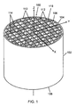
- FIG. 1 is a perspective view of a wall-flow honeycomb filter taken from the inlet end of the filter (not part of the invention).
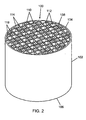
- FIG. 2 is a perspective view of a wall-flow honeycomb filter taken from the outlet end of the filter (not part of the invention).
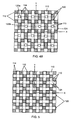
- FIG. 3 is a plan view of the cell configuration used with the wall-flow honeycomb filter of FIG. 1 , featuring quadrate-shaped inlet cell clusters(not part of the invention).
- FIGS. 4A and 4B are plan views of an alternate cell configuration for use with the wall-flow honeycomb filter of FIG. 1 , featuring flower-shaped inlet cell clusters(not part of the invention).
- FIG. 5 is a plan view of a cell configuration according to the invention for use with the wall-flow honeycomb filter of FIG. 1 , featuring cross-shaped inlet cell clusters.
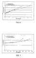
- FIG. 6 is a graph comparing backpressure vs. soot loading for a standard filter and a filter having the cell configuration depicted in FIG. 3 (not part of the invention).
- FIG. 7 is a graph comparing backpressure vs. washcoat loading for a catalyzed standard filter and a catalyzed filter having the cell configuration depicted in FIG. 3 (not part of the invention).
- FIG. 8 is a graph comparing backpressure vs. soot loading for a standard filter and a filter having the cell configuration depicted in FIG.3 (not part of the invention).
- Honeycomb wall-flow filters may provide two mechanisms for cleaning exhaust gasses. These mechanisms are (1) filtration and (2) catalysis. Filtration of soot, ash and other particulate pollutants from a gas exhaust stream, such as a diesel gas exhaust stream is accomplished by forcing the exhaust stream to enter a filter through an inlet cell which is open at an inlet face of a filter substrate, pass through a porous wall into an outlet cell which is open at an outlet face of the filter substrate. As the exhaust gas stream passes through the filter wall, particulate matter is trapped in or on the porous walls and does not pass out through the outlet of the filter. Catalysis is accomplished by flowing the exhaust gas stream past catalytic chemicals that have been imbedded in or on the surface of the walls of the filter channels.
- FIGS. 1 and 2 are perspective views of a wall-flow honeycomb filter 100 that allows a relatively high catalyst loading balanced with relatively high particulate storage capacity and relatively low backpressure or pressure drop.
- FIG. 1 shows the wall-flow honeycomb filter 100 from the inlet end of the filter
- FIG. 2 shows the wall-flow honeycomb filter 100 from the outlet end of the filter.
- the backpressure of the filter 100 is relatively low for a predetermined operational period of the filter, after which regeneration of the filter may be needed.
- the wall-flow honeycomb filter 100 may be used bare or catalyzed.
- the wall-flow honeycomb filter 100 includes a monolith 102, which may be made of a ceramic material, such as cordierite, silicon carbide, aluminum titanate, mullite or other suitable materials that can withstand high temperatures, such as those encountered during thermal regeneration of a filter.
- the monolith 102 has a skin 104.
- the cross-sectional profile of the skin 104 is typically a circle or an ellipse, but the filter 100 is not limited to a monolith 102 having a circular or elliptical cross-sectional shape.
- the monolith 102 has an inlet end face 106 and an outlet end face 108 (shown more clearly in FIG. 2 ), where the end faces 106, 108 are in opposing relation.
- the monolith 102 contains a plurality of longitudinal, generally parallel inlet cells 110 and a plurality of longitudinal, generally parallel outlet cells 112.
- An array of intersecting porous walls 114 within the monolith 102 extend from the inlet end face 106 to the outlet end face 108 of the monolith 102 along the Z-axis, also the longitudinal axis of the monolith 102.
- the porous walls 114 form partitions between adjacent inlet cells 110 and outlet cells 112 and between adjacent outlet cells 112. Referring to FIG. 1 , the ends of the outlet cells 112 are plugged or sealed with filler material 116 at the inlet end face 106 of the monolith 102 while the ends of the inlet cells 110 are open.
- the filler material 116 may or may not be flush with the end face 106.
- the ends of the outlet cells 112 are open at the outlet end face 108 of the monolith while the ends of the inlet cells 110 are plugged or sealed with filler material 118 at the outlet face 108.
- the filler material 118 may or may not be flush with the end face 108.
- the filler material, or cement or plugging material, (116 in FIG. 1 , 118 in FIG. 2 ) may contain a ceramic material, such as cordierite, aluminum titanate, mullite, silicon carbide, and/or other materials that can withstand high temperatures, such as those encountered during thermal regeneration of the filter. Such ceramic material may be mixed with a binder and plasticizer.
- particulate-laden flow such as exhaust gas from a diesel engine
- the particulate-laden flow enters the monolith 102 through the inlet cells 110, is forced into the outlet cells 112 through the adjoining porous walls 114, and exits the outlet cells 112 at the outlet end face 108 of the monolith 102.
- the porous walls 114 retain a portion of the particulates in the particulate-laden flow.
- the higher the portion of particulates excised from the flow the better the filtration efficiency of the filter.
- the structure, porosity, and thickness of the porous walls 114 are such that particulate filtration is achieved without compromising the structural integrity of the monolith 102.
- the porous walls 114 may incorporate pores having mean diameters in the range of 1 to 60 ⁇ m, or in a range from 5 to 30 ⁇ m.
- the porosity of the porous walls 114 may be in a range from 30% to 80%.
- the thickness of the porous walls 114 may range from approximately 0.002 in to 0.060 in. (0.05 mm to 1.5 mm).
- the cell density may also be selected to achieve desired filtration efficiency.
- the filter 100 may have a cell density between approximately 10 and 400 cells/in 2 (1.5 and 46.5 cells/cm 2 ), or even between 100 and 300 cells/in 2 (15.5 and 31 cells/cm 2 ).
- FIG. 3 shows a plan view of the cell configuration used in the filter in FIGS. 1 and 2 .
- the view shown in FIG. 3 corresponds to the inlet end face (106 in FIG. 1 ) of the filter (100 in FIG. 1 ).
- the ends of the inlet cells 110 are open while the ends of the outlet cells 112 are plugged or sealed.
- the reverse is true, i.e., the ends of the inlet cells 110 are plugged or sealed while the ends of the outlet cells 112 are open, as previously described.
- at least some of the inlet cells 110 are arranged in inlet cell clusters 120. In alternate embodiments, all of the inlet cells 110 may be arranged in clusters. For emphasis in FIG.
- each inlet cell cluster 120 is a group of inlet cells 110 held together in a close relationship.
- the inlet cell clusters 120 do not contain outlet cells 112.
- the inlet cells 110 are interconnected together within each cluster 120 by inlet cluster walls 124, which may or may not have the same characteristics as the porous walls 114 formed between adjoining inlet cells 110 and outlet cells 112 or between adjoining outlet cells 112.
- the inlet cluster walls 124 may incorporate pores having mean diameters in the range of 1 to 60 ⁇ m and may have a porosity in a range from 30% to 80%.
- the porosity requirement of the inlet cluster walls 124 need not be the same as that of the porous walls 114 since the inlet cluster walls 124 are not required to filter particulates.
- Each inlet cell cluster 120 has a plurality of inlet cells 110 and is bordered by outlet cells 120.
- the shape of the inlet cell cluster 120 may be quadrate, i.e., square or rectangular, or may contain quadrate clusters, or may be non-quadrate, e.g., cross-shaped.
- the shape of the inlet cells 110 may be quadrate or non-quadrate.
- the inlet cell cluster 120 and the inlet cells 110 may contain a quadrate shape, e.g., square.
- FIG. 4A shows an alternate cell configuration in which the inlet cell clusters 120 contain a quadrate shape, e.g., a flower shape, and the inlet cells 110 within each inlet cell cluster 120 have a quadrate shape, e.g., square.
- FIG. 5 shows another cell configuration, a cell configuration according to the invention, in which the inlet cell clusters 120 have a non-quadrate shape, e.g., a cross shape, but the inlet cells 110 within each inlet cell cluster 120 have a quadrate shape, e.g., square.
- FIGS. 4 and 5 are what would be seen if the filter is viewed from the inlet end. At the inlet end of the filter, the inlet cells 110 are open while the outlet cells 112 are closed or sealed.
- each inlet cell cluster 120 may include inlet cells 110 with different shapes.
- the outlet cells 112 as well as other inlet cells 110 not within an inlet cell cluster 120 may have a quadrate or a non-quadrate shape.
- each cluster of inlet cells at the inlet face are separated from adjacent clusters of inlet cells by outlet cells which are plugged at the inlet face.
- the inlet cell clusters are separated from each other by at least one outlet cell, plugged at the inlet face.
- each inlet cell cluster 120 has an aspect ratio less than 1.5.
- aspect ratio is defined as the ratio of a first dimension of the inlet cell cluster 120 measured linearly along a first axis to a second dimension of the inlet cell cluster 120 measured linearly along a second axis.
- the first axis and second axis are orthogonal to each other and to a longitudinal axis of the monolith (102 in FIG. 1 ).
- each inlet cell cluster 120 includes at least four inlet cells arranged in a 2 x 2 quadrate configuration. According to the invention, such as illustrated in FIG. 5 , each inlet cell cluster 120 has a cross shape.
- the cell configuration includes a two-dimensional (2D) quadrate (square or rectangular) array of inlet cell clusters 120.
- the 2D quadrate array has N x M dimensions, where N and M are integers greater than 1. In other words, the 2D quadrate array has N columns, and each N column has M rows.
- Each inlet cell cluster 120 in the 2D quadrate array consists of a plurality of inlet cells 110 interconnected by porous inlet cluster walls 124.
- the cell configuration includes a first 2D quadrate array of inlet cell clusters 120 and a second 2D quadrate array of inlet cell clusters 120.
- FIG. 4B identifies the inlet cell clusters 120 in the first 2D quadrate array by square markers 120a and the inlet cell clusters 120 in the second 2D quadrate array by circular markers 120b.
- the first 2D quadrate array has N x M dimensions, where N and M are integers greater than 1. In other words, the first 2D quadrate array has N columns, and each N column has M rows.
- the second 2D quadrate array has K x J dimensions, where K and J are integers greater than 1. In other words, the 2D quadrate array has K columns, and each K column has J rows.
- the second 2D quadrate array is offset from the first 2D quadrate array such that the inlet cell clusters 120 in the second 2D quadrate array are distinct from, or in a non-overlapping arrangement with, the inlet cell clusters 120 in the first 2D quadrate array.
- the cell configuration depicted in FIG. 5 has a similar array pattern to the one disclosed in FIGS. 4A and 4B .
- inlet cells (I) and outlet cells (O) wherein the repeating array, across an inlet face of a honeycomb monolith, from left to right (or along an X axis, where the arrow indicates the X axis) is:
- the repeating pattern, from top to bottom (or along the Y axis where the arrow indicates the Y axis) is:
- the pattern, which can be repeated in the X and Y directions for Example 2 ( FIG. 3 ) is:
- the pattern, which can be repeated in the X and Y directions for Example 7 ( FIG. 4A ) is:
- the cell configuration of the filter is such that the ratio of the combined cross-sectional area of the inlet cells 110 to the combined cross-sectional area of the outlet cells 112 is greater than 1.
- This definition takes into account all the inlet cells 110, including those within inlet cell clusters 120.
- the ratio of the combined cross-sectional area of the inlet cells 110 to the combined cross-sectional area of the outlet cells 112 is at least 1.25. Preferably, it is at least 1.5.
- the cross-sectional area of a cell is the area of the imprint of the cell on an end face of the filter.
- the cell configuration of the filter is also such that the combined cross-sectional area of all the inlet cells 110 within each inlet cell cluster 120 is greater than the cross-sectional area of each outlet cell 112.
- less than 100% of the porous walls within the monolith 102 are filtering walls, the filtering walls being the porous walls 114 between adjacent inlet and outlet cells 110, 112.
- the porous walls or inlet cluster walls 124 within clusters 120 are considered to be non-filtering or reduced-filtering walls because they are not located between an inlet cell and an outlet cell.
- exhaust gasses passing through the filter monolith do not necessarily need to pass through porous walls that occur within clusters in order to exit the monolith through an outlet channel, which is open (not plugged) at the outlet face.
- exhaust gasses must pass through a porous wall between an inlet cell and an outlet cell in order to exit the monolith through an outlet channel, which is open (not plugged) at the outlet face. Therefore, the inlet cluster walls 124 do not necessarily clean exhaust gasses by a filtration mechanism.
- a portion of the porous walls 114 may also be non-filtering or reduced-filtering, such as those located between adjacent outlet cells 112. These may be called outlet cell cluster walls 112.
- the inlet cluster walls 124 within clusters 120, b can provide the catalytic mechanism of cleaning exhaust gasses. These inlet cluster walls 124 within clusters 120 may provide an avenue for high catalyst loading without significantly impacting backpressure. For example, if a porous wall is required to provide both filtration and catalysis, as is the case in a traditional honeycomb filter with a checkerboard plugging pattern, the application of a catalytic layer on the porous substrate may limit the porosity of the substrate. Without being limited by the theory, the catalytic layer may fill the pores of the ceramic substrate, reducing the porosity of the material. A material with a reduced porosity will have an increased backpressure.
- a washcoat containing active catalytic species is preferably coated on the inlet cluster walls 124 and/or incorporated in the pores of the inlet cluster walls 124.
- the washcoat may also be coated on or incorporated in the pores of the filtering porous walls 114, but generally using the inlet cluster walls 124 within the clusters 120 as the main holding substrate for active catalyst species is preferred.
- the washcoat may include any known active catalytic species for purifying exhaust gas, such as catalytic species for oxidizing carbon monoxide, hydrocarbons, NOx, and soluble organic fraction of particulates, as is known in the art.
- plugging the ceramic monolith filter in the patterns illustrated in Figures 1-5 may also increase the capacity of the ceramic monolith to store soot and ash.
- soot and ash may be deposited onto inlet cluster walls. The accumulation of soot and ash on inlet cluster walls may have less impact on the build-up of backpressure.
- a coating process may occur after the monolith has been plugged, so that by dipping the filter into a slurry containing washcoat from the inlet side, only the inlet cells will be coated, and by dipping the filter into a slurry containing washcoat from the outlet side, only the outlet cells will be coated. In this way, it is possible to treat the inlet cluster walls, differently from the filtering walls, within outlet cells.
- the inlet cluster walls 124 may be coated with a washcoat by dipping a bare plugged filter (100 in FIG. 1 ) into a slurry of washcoat.
- the filter is dipped upside down, inlet end first, into the coating slurry.
- the filter is removed from the slurry and air is blown into the filter, from the outlet end face (108 in FIG. 1 ) to the inlet end face (106 in FIG. 1 ).
- the filter is then dried. If the filter is made of a ceramic material, the filter is also fired. This process of dipping, blowing, drying, and firing may be repeated several times.
- the filter may be dipped outlet end first, into a second coating solution.
- the coated filter may then be blown, dried and fired as needed. This process of dipping, blowing, drying and firing may be repeated.
- the inlet cluster walls 124 or the inlet cell cluster walls 124 may have more washcoat incorporated into the walls, than filtering walls 114, or walls which are not within a cluster of inlet cells 114.
- washcoat which may contain catalytic compounds, may be incorporated into the inlet cluster walls using the dip-coating method described above.
- Filtering walls 114 may be exposed to fewer dip-coating treatments, or no dip-coating treatments to apply washcoating.
- fluids such as exhaust gasses enter embodiments of filters of the present invention, the gas stream enters into an open inlet cell, containing inlet cluster walls which contain washcoat incorporated into the inlet cluster walls.
- the washcoat which may contain catalytic compounds
- the noxious chemicals including carbon monoxide, hydrocarbons and NOx are cleaned from the fluid via chemical catalysis. These fluids then flow through the filtering walls into outlet cells. As the fluids pass through filtering walls, particulate matter is removed from the fluid stream. Then, the fluids pass out of the filter via the open outlet cells of the filter. Because the filtering walls have been treated with washcoat or with catalytic washcoat only on the inlet-cell-side of the filtering wall, less washcoat is incorporated into the filtering walls than would be incorporated into the inlet cluster walls, which have been treated on both faces with washcoat.
- the wall-flow honeycomb filter of the present invention when differentially treated with washcoating, in embodiments, may provide increased catalytic capacity, without increasing overall filter backpressure.
- the filtering and inlet cluster walls, or the cluster and non-cluster walls may be coated, using, for example, a vacuum process.
- the vacuum process involves dipping one end of the filter into a coating slurry.
- the slurry is pumped up the filter using a vacuum pump.
- excess slurry is removed from the filter, and the filter is dried and fired.
- the process of pumping slurry, removing excess slurry, drying, and firing is repeated with the other end face of the filter.
- the vacuum process may be repeated several times to achieve a desired catalyst loading.
- a wall-flow honeycomb filter (100 in FIGS. 1 and 2 ) having a cell configuration as described above and in FIGS. 3 , 4, and 5 allows a relatively high catalyst loading without a significant increase in backpressure and reduction in particulate storage capacity.
- the filter 100 has more open cells at the inlet end face of the monolith, less filtering walls within the monolith, and more inlet cluster walls within the monolith.
- all of the walls are filtering walls.
- Particulates can deposit onto the inlet cluster walls, decreasing cake build-up on the filtering walls, and therefore lowering backpressure.
- the inlet cluster walls (124 in FIGS. 3 , 4, and 5 ) within each cluster (120 in FIGS. 3 , 4, and 5 ) can be made thinner than the filtering walls (114 in FIGS. 3 , 4, and 5 ) to increase or maximize the effective flow area of the inlet cells 110 within the clusters 120 and further lower backpressure.
- a filter with a standard checkerboard pattern, 200/12 wall-flow honeycomb filter having square inlet and outlet cells with a cell wall thickness of 12 mil (0.30 mm), cell density of 200 cells/in 2 (31 cells/cm 2 ) was made.
- the filter had a diameter of 2 inches and a length of 6 inches.
- the ratio of the combined cross-sectional area of the inlet cells to the combined cross-sectional area of the outlet cells was 1. There were no clusters of inlet cells in the filter.
- the cross-sectional area of each inlet cell was equal to the cross-sectional area of each outlet cell. 100% of the porous walls within the filter were filtering walls. The filter was not catalyzed.
- a wall-flow honeycomb filter having a cell configuration as described in FIG. 3 was made with a cell wall thickness of 12 mil (0.30 mm) and cell density of 200 cells/in 2 (31 cells/cm 2 ).
- the filter included clusters of inlet cells.
- the ratio of the combined cross-sectional area of the inlet cells to the combined cross-sectional area of the outlet cells was 1.25.
- the cross-sectional area of each cluster was about 4 times the cross-sectional area of each outlet cell.
- the inlet cluster walls within each cluster had a wall thickness of 12 mil (0.30 mm). 66% of the porous walls within the filter were filtering walls.
- the filter was not catalyzed.
- FIG. 6 shows the evolution of backpressure with increasing soot loading within the filter.
- the wall-flow honeycomb filter according to Example 2 shown by the curve marked with a triangle ( ⁇ ), having clusters of inlet cells as shown in Figure 3 , has a lower backpressure than the standard checkerboard-plugged wall-flow honeycomb filter according to Example 1, shown in Fig. 6 by the curve marked by the diamond (0).
- the standard checkerboard-plugged wall-flow honeycomb filter of Example 1 was coated with a porous titania-based washcoat (Titania DT51D product available from Millenium Chemicals - mixed with a binder such as NyacolTM AL20 available from Nyacol.
- a standard vacuum process was used to coat the filter. This included vacuum suction of the washcoat into the filtering walls several times, with drying and firing of the filter performed in between each iteration.
- the wall-flow honeycomb filter of Example 2 having clusters of inlet cells as shown in FIG. 3 , was coated with a porous titania-based washcoat (Titania DT51D product available from Millenium Chemicals - mixed with a binder such as NyacolTM AL20 available from Nyacol (note that alumina, zirconia, zeolite and the like could be used as catalyst support material).
- a porous titania-based washcoat Teitania DT51D product available from Millenium Chemicals - mixed with a binder such as NyacolTM AL20 available from Nyacol (note that alumina, zirconia, zeolite and the like could be used as catalyst support material).
- NyacolTM AL20 available from Nyacol (note that alumina, zirconia, zeolite and the like could be used as catalyst support material).
- the inlet face of the filter was dipped into a slurry of the washcoat. Then air was blown from the inlet to
- FIG. 7 shows the evolution of backpressure with increasing washcoat loading within the filter.
- the backpressure measured from standard design of Example 4 shown in FIG. 7 by the curve marked by the diamond (0) increases along the same curve as the inventive design of Example 5, until a threshold of approximately 100 g/L is reached.
- the standard filter is loaded above 100 g/L, the backpressure increases dramatically with increasing washcoat load. While both filters may provide adequate filtration when they are loaded with between 20 and 40 g/L of washcoat, as the washcoat loading increases to the 100 g/L range, the performance of the two filters deviates significantly.
- Example 5 When loaded with 100 g/L of washcoat or more, the inventive design of Example 5 (shown by the curve marked with a triangle ( ⁇ )) continues to illustrate acceptable backpressure levels. Backpressure is less affected by increasing washcoat load in the inventive design. By coating inlet cluster walls with the washcoat, more washcoat can be accommodated in the inventive design, than can be accommodated in the standard designs of Example 4.
- a wall-flow honeycomb filter having a cell configuration as described in FIG. 4A was made with a cell wall thickness of 12 mil (0.30 mm) and cell density of 200 cells/in 2 (31 cells/cm 2 ).
- the filter included clusters of inlet cells. The ratio of the combined cross-sectional area of the inlet cells to the combined cross-sectional area of the outlet cells was 2. The cross-sectional area of each cluster was about 8 times the cross-sectional area of each outlet cell.
- the inlet cluster walls within each cluster had a wall thickness of 12 mil (0.30 mm). 58% of the porous walls within the filter were filtering walls.
- the filter included clusters of inlet cells.
- the ratio of the combined cross-sectional area of the inlet cells to the combined cross-sectional area of the outlet cells was 1.67.
- the cross-sectional area of each cluster was about 5 times the cross-sectional area of each outlet cell.
- the inlet cluster walls within each cluster had a wall thickness of 12 mil (0.30 mm). 75% of the porous walls within the filter were filtering walls.
- the filter was washcoated but not catalyzed.
- Example 8 The wall-flow honeycomb filters of Example 1 and Example 8 were loaded with artificially generated soot at a rate of 8 ft 3 /min.
- FIG. 8 shows the evolution of backpressure with increasing soot loading within the filter.
- the wall-flow honeycomb filter according to Example 8 has a lower backpressure than the standard wall-flow honeycomb filter according to Example 1.
- the wall-flow honeycomb filter according to the invention has a plurality of inlet cells and outlet cells. At least a portion of the inlet cells are arranged in clusters.
- the cell configuration is such that the combined cross-sectional area of the inlet cells is greater than the combined cross-sectional area of the outlet cells.
- the cell configuration is also such that less than 100% of the porous walls within the filter are filtering walls. A reduction in the filtering walls does not significantly impact backpressure.
- the inlet cluster walls within clusters serve as supports for washcoat containing active catalytic species as well as provide additional surface area for deposition of particulates. Lower backpressure is achieved when the filter is loaded with particulates because of the filter's improved capacity to store particulates.
- the filter can be made using standard extrusion and plugging processes, with the plugging pattern modified as described for the cell configurations above.
- the inlet cluster walls can be catalyzed using a process such as described above.
- the filtering walls may also be catalyzed using standard processes.
Priority Applications (3)
| Application Number | Priority Date | Filing Date | Title |
|---|---|---|---|
| EP07301601A EP2065575B1 (en) | 2007-11-29 | 2007-11-29 | Wall-flow honeycomb filter having high-storage capacity and low backpressure |
| US12/273,916 US8236083B2 (en) | 2007-11-29 | 2008-11-19 | Wall-flow honeycomb filter having high storage capacity and low backpressure |
| CN200810189571.9A CN101518705B (zh) | 2007-11-29 | 2008-11-28 | 具有高储存能力和低背压的壁流蜂窝式过滤器 |
Applications Claiming Priority (1)
| Application Number | Priority Date | Filing Date | Title |
|---|---|---|---|
| EP07301601A EP2065575B1 (en) | 2007-11-29 | 2007-11-29 | Wall-flow honeycomb filter having high-storage capacity and low backpressure |
Publications (2)
| Publication Number | Publication Date |
|---|---|
| EP2065575A1 EP2065575A1 (en) | 2009-06-03 |
| EP2065575B1 true EP2065575B1 (en) | 2012-08-15 |
Family
ID=39286152
Family Applications (1)
| Application Number | Title | Priority Date | Filing Date |
|---|---|---|---|
| EP07301601A Active EP2065575B1 (en) | 2007-11-29 | 2007-11-29 | Wall-flow honeycomb filter having high-storage capacity and low backpressure |
Country Status (3)
| Country | Link |
|---|---|
| US (1) | US8236083B2 (zh) |
| EP (1) | EP2065575B1 (zh) |
| CN (1) | CN101518705B (zh) |
Families Citing this family (34)
| Publication number | Priority date | Publication date | Assignee | Title |
|---|---|---|---|---|
| US8282385B2 (en) * | 2008-03-28 | 2012-10-09 | Hitachi Metals, Ltd. | Die for molding ceramic honeycomb structure |
| JP5452961B2 (ja) * | 2009-03-31 | 2014-03-26 | 日本碍子株式会社 | ハニカム構造体 |
| US8444752B2 (en) * | 2009-08-31 | 2013-05-21 | Corning Incorporated | Particulate filters and methods of filtering particulate matter |
| CN102686304B (zh) * | 2009-11-30 | 2016-01-13 | 康宁股份有限公司 | 具有槽形胞间孔的蜂窝状本体装置 |
| US8609032B2 (en) * | 2010-11-29 | 2013-12-17 | Corning Incorporated | Porous ceramic honeycomb articles and methods for making the same |
| US9011583B2 (en) | 2011-04-29 | 2015-04-21 | Corning Incorporated | Article for CO2 capture having heat exchange capability |
| WO2013145266A1 (ja) * | 2012-03-30 | 2013-10-03 | トヨタ自動車株式会社 | パティキュレートフィルタ |
| CN104540584B (zh) * | 2012-04-05 | 2016-06-08 | 康宁股份有限公司 | 选定的蜂窝通道表面上的不可渗透的聚合物涂层 |
| US9062586B2 (en) * | 2012-04-05 | 2015-06-23 | Corning Incorporated | Impermeable polymer coating on selected honeycomb channel surfaces |
| GB2513364B (en) * | 2013-04-24 | 2019-06-19 | Johnson Matthey Plc | Positive ignition engine and exhaust system comprising catalysed zone-coated filter substrate |
| JP6068067B2 (ja) * | 2012-09-06 | 2017-01-25 | 日本碍子株式会社 | 目封止ハニカム構造体 |
| CN109562315B (zh) * | 2016-04-22 | 2022-09-20 | 康宁股份有限公司 | 矩形出口蜂窝结构、颗粒过滤器、挤出模具及其制造方法 |
| CN110612082A (zh) | 2017-04-11 | 2019-12-24 | 强生消费者公司 | 可延展的敷料 |
| JP6887300B2 (ja) * | 2017-05-12 | 2021-06-16 | 日本碍子株式会社 | ハニカムフィルタ |
| JP6887303B2 (ja) * | 2017-05-12 | 2021-06-16 | 日本碍子株式会社 | ハニカムフィルタ |
| JP6887302B2 (ja) * | 2017-05-12 | 2021-06-16 | 日本碍子株式会社 | ハニカムフィルタ |
| JP6887301B2 (ja) * | 2017-05-12 | 2021-06-16 | 日本碍子株式会社 | ハニカムフィルタ |
| FR3066924B1 (fr) * | 2017-05-31 | 2019-07-12 | Saint-Gobain Centre De Recherches Et D'etudes Europeen | Structure filtrante a membrane |
| JP7068453B2 (ja) | 2017-11-21 | 2022-05-16 | コーニング インコーポレイテッド | 高灰ストレージの、パターンで塞がれるハニカム体及びパティキュレートフィルタ |
| USD879972S1 (en) | 2018-04-11 | 2020-03-31 | Johnson & Johnson Consumer Inc. | Adhesive bandage with decorated pad |
| USD880705S1 (en) | 2018-04-11 | 2020-04-07 | Johnson & Johnson Consumer Inc. | Adhesive bandage with decorated pad |
| USD879973S1 (en) | 2018-04-11 | 2020-03-31 | Johnson & Johnson Consumer Inc. | Adhesive bandage with decorated pad |
| JP7155292B2 (ja) | 2018-05-04 | 2022-10-18 | コーニング インコーポレイテッド | 高いアイソスタティック強度のハニカム構造およびハニカム構造用の押出ダイ |
| EP3787772A2 (en) | 2018-05-04 | 2021-03-10 | Corning Incorporated | Outlet-coated ceramic honeycomb bodies and methods of manufacturing same |
| USD887564S1 (en) | 2018-06-27 | 2020-06-16 | Johnson & Johnson Consumer Inc. | Adhesive bandage with decorated pad |
| USD879975S1 (en) | 2018-06-27 | 2020-03-31 | Johnson & Johnson Consumer Inc. | Adhesive bandage with decorated pad |
| USD887563S1 (en) | 2018-06-27 | 2020-06-16 | Johnson & Johnson Consumer Inc. | Adhesive bandage with decorated pad |
| USD879974S1 (en) | 2018-06-27 | 2020-03-31 | Johnson & Johnson Consumer Inc. | Adhesive bandage with decorated pad |
| WO2020047249A1 (en) | 2018-08-31 | 2020-03-05 | Corning Incorporated | Cordierite-indialite-pseudobrookite structured ceramic bodies, batch composition mixtures, and methods of manufacturing ceramic bodies therefrom |
| CN113272042B (zh) | 2018-11-16 | 2022-10-04 | 康宁股份有限公司 | 含堇青石的陶瓷体、批料组合物混合物和含堇青石的陶瓷体的制造方法 |
| USD913507S1 (en) | 2018-12-10 | 2021-03-16 | Johnson & Johnson Consumer Inc. | Adhesive bandage with decorated pad |
| USD918398S1 (en) | 2018-12-10 | 2021-05-04 | Johnson & Johnson Consumer Inc. | Adhesive bandage with decorated pad |
| WO2020185484A1 (en) | 2019-03-08 | 2020-09-17 | Benesi Steve C | Filter apparatus, filter disc sectors, filter elements and uses |
| USD928912S1 (en) * | 2020-02-12 | 2021-08-24 | Unicat Catalyst Technologies, Inc. | Filter |
Family Cites Families (34)
| Publication number | Priority date | Publication date | Assignee | Title |
|---|---|---|---|---|
| US4419108A (en) | 1982-02-22 | 1983-12-06 | Corning Glass Works | Filter apparatus and method of filtering |
| US4416676A (en) * | 1982-02-22 | 1983-11-22 | Corning Glass Works | Honeycomb filter and method of making it |
| US4420316A (en) * | 1982-02-22 | 1983-12-13 | Corning Glass Works | Filter apparatus and method of making it |
| US4417908A (en) | 1982-02-22 | 1983-11-29 | Corning Glass Works | Honeycomb filter and method of making it |
| US4415344A (en) | 1982-03-01 | 1983-11-15 | Corning Glass Works | Diesel particulate filters for use with smaller diesel engines |
| US4830749A (en) * | 1986-07-15 | 1989-05-16 | Ngk Insulators, Ltd. | Liquid waste filtering apparatus |
| JP3147372B2 (ja) * | 1990-10-10 | 2001-03-19 | 株式会社日本自動車部品総合研究所 | 排気ガス微粒子捕集用フィルタ |
| US5114581A (en) * | 1991-01-10 | 1992-05-19 | Ceramem Corporation | Back-flushable filtration device and method of forming and using same |
| US20010026838A1 (en) * | 1996-06-21 | 2001-10-04 | Engelhard Corporation | Monolithic catalysts and related process for manufacture |
| US6303368B1 (en) * | 1998-10-07 | 2001-10-16 | Corning Incorporated | Device for liquid or gas process streams and method of making and using same |
| US6428755B1 (en) * | 1999-10-04 | 2002-08-06 | Ford Global Technologies, Inc. | Catalyst assembly for an exhaust gas system |
| DE10037403A1 (de) * | 2000-08-01 | 2002-02-14 | Daimler Chrysler Ag | Partikelfilter |
| US6508852B1 (en) * | 2000-10-13 | 2003-01-21 | Corning Incorporated | Honeycomb particulate filters |
| JP3997825B2 (ja) * | 2001-06-28 | 2007-10-24 | 株式会社デンソー | セラミックフィルタおよび触媒付セラミックフィルタ |
| US20030041730A1 (en) * | 2001-08-30 | 2003-03-06 | Beall Douglas M. | Honeycomb with varying channel size |
| JP2004000896A (ja) | 2002-03-25 | 2004-01-08 | Ngk Insulators Ltd | ハニカムフィルター |
| JP3872384B2 (ja) * | 2002-06-13 | 2007-01-24 | トヨタ自動車株式会社 | 排ガス浄化フィルタ触媒 |
| DE10238770A1 (de) | 2002-08-23 | 2004-03-11 | Umicore Ag & Co.Kg | Vorrichtung zur Entfernung von Rußpartikeln aus dem Abgas eines Dieselmotors |
| US7326270B2 (en) | 2002-09-13 | 2008-02-05 | Ibiden Co., Ltd. | Filter |
| JP3874270B2 (ja) * | 2002-09-13 | 2007-01-31 | トヨタ自動車株式会社 | 排ガス浄化フィルタ触媒及びその製造方法 |
| US6946013B2 (en) * | 2002-10-28 | 2005-09-20 | Geo2 Technologies, Inc. | Ceramic exhaust filter |
| US7574796B2 (en) * | 2002-10-28 | 2009-08-18 | Geo2 Technologies, Inc. | Nonwoven composites and related products and methods |
| WO2004113252A1 (ja) | 2003-06-23 | 2004-12-29 | Ibiden Co., Ltd. | ハニカム構造体 |
| DE10330680A1 (de) * | 2003-07-08 | 2004-07-08 | J. Eberspächer GmbH & Co. KG | Partikelfilter und zugehöriges Herstellungsverfahren |
| DE10335785A1 (de) * | 2003-08-05 | 2005-03-10 | Umicore Ag & Co Kg | Katalysatoranordnung und Verfahren zur Reinigung des Abgases von mager betriebenen Verbrennungsmotoren |
| US7247184B2 (en) | 2003-09-25 | 2007-07-24 | Corning Incorporated | Asymmetric honeycomb wall-flow filter having improved structural strength |
| US7601194B2 (en) | 2003-09-25 | 2009-10-13 | Corning Incorporated | Asymmetric honeycomb wall-flow filter having improved structural strength |
| FR2860993B1 (fr) * | 2003-10-16 | 2006-06-16 | Sicat | Filtre catalytique a base de carbure de silicium (b-sic) pour la combustion des suies issues des gaz d'echappement d'un moteur a combustion |
| PL1676620T5 (pl) * | 2003-10-20 | 2012-10-31 | Ibiden Co Ltd | Struktura plastra miodu |
| JP4492143B2 (ja) | 2004-02-06 | 2010-06-30 | トヨタ自動車株式会社 | 排気ガスのパーティキュレートフィルタ |
| FR2874647B1 (fr) | 2004-08-25 | 2009-04-10 | Saint Gobain Ct Recherches | Bloc filtrant a ailettes pour la filtration de particules contenues dans les gaz d'echappement d'un moteur a combustion interne |
| US7722829B2 (en) * | 2004-09-14 | 2010-05-25 | Basf Catalysts Llc | Pressure-balanced, catalyzed soot filter |
| WO2008011146A1 (en) * | 2006-07-21 | 2008-01-24 | Dow Global Technologies Inc. | Improved zone catalyzed soot filter |
| WO2008066795A2 (en) | 2006-11-29 | 2008-06-05 | Corning Incorporated | Wall-flow honeycomb filter with hexagonal channel symmetry |
-
2007
- 2007-11-29 EP EP07301601A patent/EP2065575B1/en active Active
-
2008
- 2008-11-19 US US12/273,916 patent/US8236083B2/en active Active
- 2008-11-28 CN CN200810189571.9A patent/CN101518705B/zh active Active
Also Published As
| Publication number | Publication date |
|---|---|
| US8236083B2 (en) | 2012-08-07 |
| US20090139193A1 (en) | 2009-06-04 |
| EP2065575A1 (en) | 2009-06-03 |
| CN101518705A (zh) | 2009-09-02 |
| CN101518705B (zh) | 2014-07-23 |
Similar Documents
| Publication | Publication Date | Title |
|---|---|---|
| EP2065575B1 (en) | Wall-flow honeycomb filter having high-storage capacity and low backpressure | |
| US7503957B2 (en) | Honeycomb structure, method of manufacturing the same, die for forming, and discharge fluid purification system | |
| KR102605894B1 (ko) | 막을 가진 촉매 벽 유동형 필터 | |
| CN110314711B (zh) | 蜂窝过滤器 | |
| CN110314682B (zh) | 蜂窝过滤器 | |
| JP2010227767A (ja) | ハニカムフィルタ | |
| EP1470862B1 (en) | Honeycomb filter, its manufacturing, exhaust gas purification system using it | |
| US11746061B2 (en) | Outlet-coated ceramic honeycomb bodies and methods of manufacturing same | |
| CN110314683B (zh) | 蜂窝过滤器 | |
| KR20090092291A (ko) | 개선된 매연 필터 | |
| EP2108448A2 (en) | Honeycomb catalyst body | |
| KR20150015444A (ko) | 축방향으로 섹션화된 세라믹 허니콤 조립체 | |
| CN110314706B (zh) | 催化剂负载用蜂窝结构体及其制造方法 | |
| CN107965368B (zh) | 封孔蜂窝结构体 | |
| CN111148890B (zh) | 微粒过滤器上的scr催化涂层 | |
| CN113039004B (zh) | 具有不同水力直径的通道阵列的蜂窝体及其制造方法 | |
| JP2005118747A (ja) | ハニカム構造体 | |
| CN113457314B (zh) | 蜂窝过滤器 | |
| EP3714139B1 (en) | High ash storage, pattern-plugged, honeycomb bodies and particulate filters | |
| CN111699038A (zh) | 废气净化催化剂 | |
| CN112041065A (zh) | 废气净化催化剂的制造方法 | |
| CN115121063B (zh) | 蜂窝过滤器 | |
| CN115126575B (zh) | 蜂窝过滤器 | |
| JP6635757B2 (ja) | ハニカムフィルタ | |
| CN111699039A (zh) | 废气净化催化剂 |
Legal Events
| Date | Code | Title | Description |
|---|---|---|---|
| PUAI | Public reference made under article 153(3) epc to a published international application that has entered the european phase |
Free format text: ORIGINAL CODE: 0009012 |
|
| AK | Designated contracting states |
Kind code of ref document: A1 Designated state(s): AT BE BG CH CY CZ DE DK EE ES FI FR GB GR HU IE IS IT LI LT LU LV MC MT NL PL PT RO SE SI SK TR |
|
| AX | Request for extension of the european patent |
Extension state: AL BA HR MK RS |
|
| 17P | Request for examination filed |
Effective date: 20091102 |
|
| 17Q | First examination report despatched |
Effective date: 20091126 |
|
| AKX | Designation fees paid |
Designated state(s): DE FR |
|
| GRAP | Despatch of communication of intention to grant a patent |
Free format text: ORIGINAL CODE: EPIDOSNIGR1 |
|
| GRAS | Grant fee paid |
Free format text: ORIGINAL CODE: EPIDOSNIGR3 |
|
| GRAA | (expected) grant |
Free format text: ORIGINAL CODE: 0009210 |
|
| AK | Designated contracting states |
Kind code of ref document: B1 Designated state(s): DE FR |
|
| REG | Reference to a national code |
Ref country code: DE Ref legal event code: R096 Ref document number: 602007024738 Country of ref document: DE Effective date: 20121011 |
|
| PLBE | No opposition filed within time limit |
Free format text: ORIGINAL CODE: 0009261 |
|
| STAA | Information on the status of an ep patent application or granted ep patent |
Free format text: STATUS: NO OPPOSITION FILED WITHIN TIME LIMIT |
|
| 26N | No opposition filed |
Effective date: 20130516 |
|
| REG | Reference to a national code |
Ref country code: DE Ref legal event code: R097 Ref document number: 602007024738 Country of ref document: DE Effective date: 20130516 |
|
| REG | Reference to a national code |
Ref country code: FR Ref legal event code: PLFP Year of fee payment: 9 |
|
| REG | Reference to a national code |
Ref country code: FR Ref legal event code: PLFP Year of fee payment: 10 |
|
| REG | Reference to a national code |
Ref country code: FR Ref legal event code: PLFP Year of fee payment: 11 |
|
| REG | Reference to a national code |
Ref country code: FR Ref legal event code: PLFP Year of fee payment: 12 |
|
| PGFP | Annual fee paid to national office [announced via postgrant information from national office to epo] |
Ref country code: FR Payment date: 20191029 Year of fee payment: 13 |
|
| PG25 | Lapsed in a contracting state [announced via postgrant information from national office to epo] |
Ref country code: FR Free format text: LAPSE BECAUSE OF NON-PAYMENT OF DUE FEES Effective date: 20201130 |
|
| REG | Reference to a national code |
Ref country code: DE Ref legal event code: R082 Ref document number: 602007024738 Country of ref document: DE Representative=s name: CBDL PATENTANWAELTE GBR, DE |
|
| P01 | Opt-out of the competence of the unified patent court (upc) registered |
Effective date: 20230527 |
|
| PGFP | Annual fee paid to national office [announced via postgrant information from national office to epo] |
Ref country code: DE Payment date: 20231010 Year of fee payment: 17 |