EP2065175B1 - Rundlaufpresse - Google Patents
Rundlaufpresse Download PDFInfo
- Publication number
- EP2065175B1 EP2065175B1 EP08018777.6A EP08018777A EP2065175B1 EP 2065175 B1 EP2065175 B1 EP 2065175B1 EP 08018777 A EP08018777 A EP 08018777A EP 2065175 B1 EP2065175 B1 EP 2065175B1
- Authority
- EP
- European Patent Office
- Prior art keywords
- control cam
- radially
- cam
- cam part
- rotary tablet
- Prior art date
- Legal status (The legal status is an assumption and is not a legal conclusion. Google has not performed a legal analysis and makes no representation as to the accuracy of the status listed.)
- Not-in-force
Links
- 101100390736 Danio rerio fign gene Proteins 0.000 description 2
- 101100390738 Mus musculus Fign gene Proteins 0.000 description 2
- 239000000463 material Substances 0.000 description 2
- 238000004140 cleaning Methods 0.000 description 1
- 238000009434 installation Methods 0.000 description 1
- 230000003993 interaction Effects 0.000 description 1
- 238000004519 manufacturing process Methods 0.000 description 1
- 239000000843 powder Substances 0.000 description 1
- 239000012254 powdered material Substances 0.000 description 1
- 238000009420 retrofitting Methods 0.000 description 1
- 238000007789 sealing Methods 0.000 description 1
Images


Classifications
-
- B—PERFORMING OPERATIONS; TRANSPORTING
- B30—PRESSES
- B30B—PRESSES IN GENERAL
- B30B11/00—Presses specially adapted for forming shaped articles from material in particulate or plastic state, e.g. briquetting presses, tabletting presses
- B30B11/02—Presses specially adapted for forming shaped articles from material in particulate or plastic state, e.g. briquetting presses, tabletting presses using a ram exerting pressure on the material in a moulding space
- B30B11/08—Presses specially adapted for forming shaped articles from material in particulate or plastic state, e.g. briquetting presses, tabletting presses using a ram exerting pressure on the material in a moulding space co-operating with moulds carried by a turntable
-
- B—PERFORMING OPERATIONS; TRANSPORTING
- B30—PRESSES
- B30B—PRESSES IN GENERAL
- B30B15/00—Details of, or accessories for, presses; Auxiliary measures in connection with pressing
- B30B15/0023—Drive arrangements for movable carriers, e.g. turntables
-
- Y—GENERAL TAGGING OF NEW TECHNOLOGICAL DEVELOPMENTS; GENERAL TAGGING OF CROSS-SECTIONAL TECHNOLOGIES SPANNING OVER SEVERAL SECTIONS OF THE IPC; TECHNICAL SUBJECTS COVERED BY FORMER USPC CROSS-REFERENCE ART COLLECTIONS [XRACs] AND DIGESTS
- Y10—TECHNICAL SUBJECTS COVERED BY FORMER USPC
- Y10S—TECHNICAL SUBJECTS COVERED BY FORMER USPC CROSS-REFERENCE ART COLLECTIONS [XRACs] AND DIGESTS
- Y10S425/00—Plastic article or earthenware shaping or treating: apparatus
- Y10S425/005—Cammed
Definitions
- the invention relates to a rotary press according to the preamble of patent claim 1.
- a rotor In a rotary press, a rotor is rotatably mounted and driven in a frame about a vertical axis.
- the usually one-piece rotor body includes an upper and a lower punch holder for upper and lower punch, which are guided axially parallel in holes.
- the press dies cooperate with bores of a die plate, which is either formed integrally with the rotor body or represents a separate part.
- a die plate which is either formed integrally with the rotor body or represents a separate part.
- cams are mounted on curve holders in the frame, which cooperate with the top and / or bottom of the head of the ram. Only in the area of pressing stations with upper and lower pressure rollers are the press punches not guided by control cams.
- the invention has for its object to provide a rotary press, can be removed in the control cams without removing the ram before.
- the control cam parts are releasably attached to the cam carrier and can - if solved - are moved radially away from the punch heads, to the extent that they can be taken parallel to the rotor axis past the stamp heads up or down. It is understood that the control cam parts can only be moved radially away from the side of the press dies, against which they rest against the press die heads.
- the cam sections are each assigned to a separate control curve part. Both cam parts are releasably attached to the cam carrier. Both cam parts have a cam portion which engage on opposite sides of the heads of the ram.
- the arrangement of the control cam parts relative to the cam carrier is such that the control cam parts after release from the cam carrier can first be moved radially apart and then moved parallel to the axis of the rotor.
- the cam member in the invention is divided into two parts and the items can be removed separately, without the need for the press stamps must be removed beforehand.
- the press punches can therefore remain in the press.
- the change of the cam elements can go quickly in the invention, whereby less downtime during retrofitting are necessary.
- the invention in the use of rotary presses, in which it is intended, also for cleaning rotor and ram to leave in the press.
- This is possible by surrounding the rotor with a sealing housing which forms a relatively small pressing space within the press housing.
- the housing is designed so that the protruding from the rotor upper and lower ends of the ram, which cooperate with the cams, outside the baling chamber lie.
- the press punches are themselves sealingly guided in the bores of the stamp holders.
- control cam parts have radial flange sections, wherein the flange section of the radially outer control cam section covers the flange section of the radially inner control cam section.
- flange portions are tensioned against each other when they are fastened by means of screws on the cam carrier.
- cam parts there are different ways of mounting the cam parts on the cam carrier conceivable.
- One according to an embodiment of the invention is that the radially inner cam part is attached to the cam carrier and the radially outer cam part is fixed to the radially inner cam part.
- the inner cam part has a radially outwardly pointing flange portion which covers the outer cam part.
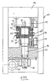
- a frame 10 of a rotary press after Fig. 2 has a lower platform 12 and an upper platform 14.
- the lower platform 12 supports a drive shaft, which is driven via a gear 18 by an electric motor 20.
- On the shaft 16 is seated a rotor 22, which has an upper punch holder 24 and a lower punch holder 26 for upper punch 28 and lower punch 30.
- the pressing rams 28, 30 cooperate with bores of a die plate 32, which in the case shown formed integrally with the rotor 22 is.
- FIG. 2 An upper cam carrier 34 holds a cam member 36.
- a lower cam carrier 38 holds a lower cam member 40.
- An upper pressure roller 42 and a lower pressure roller 44 In the area of the pressure rollers press punches 28th , 30 pressed into the die holes for the purpose of compressing the powdery material in the holes, previously entered by a filling device, not shown in the holes has been.
- the revolving press shown Fig. 2 corresponds to the state of the art.
- a development of the rotor is shown. Identical parts are provided with the same reference numerals.
- a filling device is shown which fills die bores 48 of the die plate 32 with powdered material. It can be seen that outside the pressure rollers 42, 44 or 42a, 44a, the heads of the pressing rams 28, 30 are guided by means of upper control cam elements 50 and lower control cam elements 52. In area 54, filling takes place. In area 56, a metering of the pressing material takes place, the position of the lower punches 30 predetermining the filling volume. By the pressure rollers 42, 44 is a pre-pressing. By the pressure rollers 42a, 44a, the main pressing occurs. In area 58, the compacts are ejected from the lower punches 30.
- FIGS. 3 and 4 is perspectively the rotor 22 according to Fig. 2 indicated.
- Fig. 3 Holes 62 which lead upper punch 28.
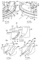
- a cam member 64 is shown, which is composed of a radially outer cam member 66 and a radially inner cam member 68.
- Each cam part 66, 68 has a cam portion 70 and 72, respectively.
- the control cam sections 70, 72 form a control cam in the area shown on the circumference of the rotor 22.
- Cam portions 70, 72 engage under the punch head 60, wherein a further cam portion 74 cooperates with the top of the punch head 60.
- the outer control part 66 has a radially inwardly pointing flange 76.
- Inner control part 68 has a radially inwardly pointing flange 78. The latter lies on a flat surface of a cam carrier 80, and the flange 76 rests on an associated higher surface of the cam carrier 80.
- the two flanges 76, 78 are made by means of screws, as at 82 in FIGS. 3 and 4 can be seen attached to the cam carrier 80.
- the outer cam part 66 can be moved radially outward until abutting a boundary 90 of the rotor 22.
- the punch head 60 moves into the free space 84 and abuts against the facing side of the recess of the Control parts 66 on.
- the control part 66 can now be moved up and released from the punch head 60.
- Fig. 11 is shown how subsequently the cam member 68 can be moved radially inward and eliminates the free space 86. In this case, the cam member 68 abuts against the cam carrier 80. How out Fig. 12 then to see, also the inner control part 68 can be removed upwards.
- control cam element 64 can be completely removed without the press ram 28 having to be removed. Nevertheless, it is of course possible to remove the press dies if, for example, another specification is to be used.
- FIGS. 3 and 4 or 8 to 12 illustrated cam member 64 is in Fig. 5 shown pulled apart.
- the FIGS. 6 and 7 show other constructive embodiments.
- the embodiment according to Fig. 6 has an inner control part 68a and an outer control part 66a.
- the cam sections 70, 72 are similar to those Fig. 5 , While in Fig. 5 Both control parts 66, 68 are secured via flanges 76, 78 on the cam carrier 80, in the embodiment according to Fig. 6 the outer control part 66a is fixed to the inner control part 68a.
- a radially outwardly facing flange 92 of the inner control part 68a covers the top of the outer control part 66a.
- the outer control part 66b largely follows the control part 66a Fig. 6 , It also recognizes a bore 94 for the screw with the inner control part 68b, which also has holes 96. In the case shown, the upper sides of the control parts 68b, 66b are aligned.
- the inner control part 68b is in turn by means of the flange 78 to not shown in these figures cam carrier 80 according to the FIGS. 8 to 12 attached.
Landscapes
- Engineering & Computer Science (AREA)
- Mechanical Engineering (AREA)
- Powder Metallurgy (AREA)
- Press Drives And Press Lines (AREA)
- Processing And Handling Of Plastics And Other Materials For Molding In General (AREA)
Description
- Die Erfindung bezieht sich auf eine Rundlaufpresse nach dem Oberbegriff des Patentanspruchs 1.
- Bei einer Rundlaufpresse ist ein Rotor in einem Gestell um eine Hochachse drehbar gelagert und angetrieben. Der zumeist einteilige Rotorkörper enthält eine obere und eine untere Stempelaufnahme für Ober- und Unterstempel, welche in Bohrungen achsparallel geführt sind. Die Pressstempel wirken mit Bohrungen einer Matrizenscheibe zusammen, die entweder einteilig mit dem Rotorkörper geformt ist oder ein getrenntes Teil darstellt. Aus
DE 10 2004 040 163 ist auch bekannt geworden, die Matrizenscheibe aus einzelnen Segmenten zusammenzusetzen. - Während der Umdrehung des Rotors werden die Pressstempel axial bewegt. Ein Großteil der Bewegungen wird von Steuerkurven bewerkstelligt. Zu diesem Zweck sind an Kurvenhaltern im Gestell Steuerkurvenelemente angebracht, welche mit der Oberseite und/oder der Unterseite des Kopfs der Pressstempel zusammenwirken. Lediglich im Bereich von Pressstationen mit oberer und unterer Druckrolle sind die Pressstempel nicht von Steuerkurven geführt.
- Aus Gründen des Verschleißes oder einer Änderung der Spezifikation ist erforderlich, die Führungskurvenelemente auszubauen und durch andere zu ersetzen. Hierfür ist im Stand der Technik erforderlich, Maschinenverkleidungsteile und die Fülleinrichtung aus dem Pressengestell zu entfernen und mehrere Stempel oder die Matrizenscheibe mit den Pressstempeln auszubauen. Außerdem ist in der Maschine befindliches Pulver abzusaugen. Der Montageaufwand ist daher erheblich. Außerdem ist während der Montagezeit der Betrieb der Rundlaufpresse naturgemäß unterbrochen. Der Austausch von Steuerkurvenelementen führt daher zu einer erheblichen Unterbrechung der Produktionszeit.
- Aus
WO 02/074528 - Aus
JP 11 207499 - Aus
WO 03/020499 - Der Erfindung liegt die Aufgabe zugrunde, eine Rundlaufpresse zu schaffen, bei der Steuerkurvenelemente ausgebaut werden können, ohne die Pressstempel vorher zu entfernen.
- Diese Aufgabe wird durch die Merkmale des Patentanspruchs 1 gelöst.
- Bei der Erfindung ist mindestens ein in Laufrichtung der Pressstempel die Pressstempelköpfe radial innen und/oder ein radial außen führendes Steuerkurventeil vorgesehen. Erfindungsgemäß sind die Steuerkurventeile lösbar am Kurventräger befestigt und können - wenn gelöst - radial von den Stempelköpfen fort bewegt werden, und zwar soweit, dass sie parallel zur Rotorachse an den Stempelköpfen vorbei nach oben oder unten herausgenommen werden können. Es versteht sich, dass die Steuerkurventeile nur von der Seite von den Pressstempeln radial fort bewegt werden kann, an der sie an den Pressstempelköpfen anliegen.
- Bei gegenüberliegend an den Stempelköpfen angreifenden Steuerkurventeilen sind die Steuerkurvenabschnitte jeweils einem eigenen Steuerkurventeil zugeordnet. Beide Steuerkurventeile sind lösbar am Kurventräger befestigt. Beide Steuerkurventeile weisen einen Steuerkurvenabschnitt auf, die auf gegenüberliegenden Seiten an den Köpfen der Pressstempel angreifen. Die Anordnung der Steuerkurventeile relativ zum Kurventräger ist derart, dass die Steuerkurventeile nach dem Lösen vom Kurventräger zunächst radial auseinanderbewegbar und anschließend parallel zur Achse des Rotors bewegt werden können.
- Das Steuerkurvenelement bei der Erfindung ist zweigeteilt und die Einzelteile können getrennt entfernt werden, ohne dass hierfür die Pressstempel zuvor entnommen werden müssen. Die Pressstempel können daher in der Presse verbleiben. Der Wechsel der Steuerkurvenelemente kann bei der Erfindung schnell vonstatten gehen, wodurch geringere Stillstandszeiten bei einer Umrüstung nötig werden.
- Besonders vorteilhaft ist die Erfindung bei dem Einsatz von Rundlaufpressen, bei denen beabsichtigt ist, auch zu Reinigungszwecken Rotor und Pressstempel in der Presse zu belassen. Dies ist möglich, indem der Rotor von einem dichtenden Gehäuse umgeben ist, das einen relativ kleinen Pressraum innerhalb des Pressengehäuses bildet. Das Gehäuse ist so ausgeführt, dass die aus dem Rotor herausragenden oberen und unteren Enden der Pressstempel, die mit den Steuerkurven zusammenwirken, außerhalb des Pressraums liegen. Die Pressstempel sind ihrerseits dichtend in den Bohrungen der Stempelaufnahmen geführt.
- In einer Ausgestaltung der Erfindung weisen die Steuerkurventeile radiale Flanschabschnitte auf, wobei der Flanschabschnitt des radial äußeren Steuerkurventeils den Flanschabschnitt des radial inneren Steuerkurventeils überdeckt. In einer weiteren Ausführungsform ist vorgesehen, dass die Flanschabschnitte gegeneinander gespannt sind, wenn sie mittels Schrauben am Kurventräger befestigt sind.
- Es sind verschiedene Anbringungsweisen der Steuerkurventeile am Kurventräger denkbar. Eine besteht nach einer Ausgestaltung der Erfindung darin, dass das radial innere Steuerkurventeil am Kurventräger befestigt ist und das radial äußere Steuerkurventeil am radial inneren Steuerkurventeil befestigt ist. Alternativ kann nach einer anderen Ausgestaltung der Erfindung vorgesehen sein, dass das innere Steuerkurventeil einen radial nach außen weisen Flanschabschnitt aufweist, der den äußeren Steuerkurventeil überdeckt.
- Ausführungsbeispiele der Erfindung werden nachfolgend anhand von Zeichnungen näher erläutert.
- Fig. 1
- zeigt schematisch die Abwicklung eines Rotors einer Tablettenpresse gemäß
Fig. 2 . - Fig. 2
- zeigt den schematischen Aufbau einer Rundlaufpresse mit Führungskurvenelementen nach dem Stand der Technik.
- Fig. 3
- zeigt perspektivisch einen Teil eines Rotors mit erfindungsgemäßem Steuerkurvenelement.
- Fig. 4
- zeigt eine ähnliche Darstellung wie
Fig. 3 , jedoch von der entgegengesetzten Seite des Steuerkurvenelements. - Fig. 5
- zeigt perspektivisch die auseinandergebauten Steuerkurventeile des Steuerkurvenelements nach den
Fign. 3 und 4 . - Fig. 6
- zeigt eine zweite Ausführungsform eines Steuerkurvenelements.
- Fig. 7
- zeigt eine dritte Ausführungsform eines Steuerkurvenelements.
- Fig. 8
- zeigt einen Schnitt durch die Darstellung nach
Fig. 4 . - Fign. 9 - 12
- zeigen die Schritte zum Ausbau der Steuerkurventeile des Steuerkurvenelements nach
Fig. 8 . - Ein Gestell 10 einer Rundlaufpresse nach
Fig. 2 weist eine untere Plattform 12 und eine obere Plattform 14 auf. Die untere Plattform 12 lagert eine Antriebswelle, welche über ein Getriebe 18 von einem Elektromotor 20 angetrieben ist. Auf der Welle 16 sitzt ein Rotor 22, der eine obere Stempelaufnahme 24 und eine untere Stempelaufnahme 26 aufweist für Oberstempel 28 und Unterstempel 30. Die Pressstempel 28, 30 wirken mit Bohrungen einer Matrizenscheibe 32 zusammen, die im gezeigten Fall einteilig mit dem Rotor 22 geformt ist. - In
Fig. 2 hält ein oberer Kurventräger 34 ein Steuerkurvenelement 36. Ein unterer Kurventräger 38 hält ein unteres Steuerkurvenelement 40. Im Bereich einer Druckstation wirken auf die Köpfe der Pressstempel 28, 30 eine obere Druckrolle 42 und eine untere Druckrolle 44. Im Bereich der Druckrollen werden die Pressstempel 28, 30 in die Matrizenbohrungen hineingepresst zwecks Komprimierung des pulverförmigen Materials in den Bohrungen, das zuvor von einer nicht gezeigten Füllvorrichtung in die Bohrungen eingetragen worden ist. Die gezeigte Rundlaufpresse nachFig. 2 entspricht dem Stand der Technik. - In
Fig. 1 ist eine Abwicklung des Rotors gezeigt. Gleiche Teile sind mit gleichen Bezugszeichen versehen. Bei 46 ist eine Füllvorrichtung gezeigt, welche Matrizenbohrungen 48 der Matrizenscheibe 32 mit pulverförmigem Material füllt. Man erkennt, dass außerhalb der Druckrollen 42, 44 bzw. 42a, 44a die Köpfe der Pressstempel 28, 30 mit Hilfe von oberen Steuerkurvenelementen 50 und unteren Steuerkurvenelementen 52 geführt sind. Im Bereich 54 findet das Befüllen statt. Im Bereich 56 findet ein Dosieren des Pressmaterials statt, wobei die Position der Unterstempel 30 das Füllvolumen vorgeben. Durch die Druckrollen 42, 44 erfolgt eine Vorpressung. Durch die Druckrollen 42a, 44a erfolgt die Hauptpressung. Im Bereich 58 werden die Presslinge von den Unterstempeln 30 ausgestoßen. - In den
Fign. 3 und 4 ist perspektivisch der Rotor 22 gemäßFig. 2 angedeutet. Man erkennt bei 28 einen Oberstempel mit einem Kopf 60. Außerdem erkennt man inFig. 3 Bohrungen 62, welche Oberstempel 28 führen. In denFign. 3 und 4 ist außerdem ein Steuerkurvenelement 64 gezeigt, das aus einem radial äußeren Steuerkurventeil 66 und einem radial inneren Steuerkurventeil 68 zusammengesetzt ist. Jedes Steuerkurventeil 66, 68 besitzt einen Steuerkurvenabschnitt 70 bzw. 72. Zusammengesetzt, wie in denFign. 3 und 4 gezeigt, bilden die Steuerkurvenabschnitte 70, 72 eine Steuerkurve in dem gezeigten Bereich am Umfang des Rotors 22. - Das Zusammenwirken der Steuerkurventeile 66, 68 ist in
Fig. 8 zu erkennen. Steuerkurvenabschnitte 70, 72 untergreifen den Stempelkopf 60, wobei ein weiterer Steuerkurvenabschnitt 74 mit der Oberseite des Stempelkopfs 60 zusammenwirkt. Das äußere Steuerteil 66 weist einen radial nach innen weisenden Flansch 76 auf. Inneres Steuerteil 68 weist einen radial nach innen weisenden Flansch 78 aus. Letzterer liegt auf einer planen Fläche eines Kurventrägers 80, und der Flansch 76 liegt auf einer zugeordneten höheren Fläche des Kurventrägers 80 auf. Die beiden Flansche 76, 78 werden mit Hilfe von Schrauben, wie sie bei 82 inFign. 3 und 4 zu erkennen sind, am Kurventräger 80 befestigt. Man erkennt ausFig. 8 , dass die Ausnehmung im Kurvensteuerteil 66, welche den Kopf 60 des Stempels 28 aufnimmt, breiter ist als für die Führung erforderlich wäre. Es ist mithin ein Freiraum 84 geschaffen. Man erkennt ferner, dass zwischen dem Kurventräger 80 und dem Steuerteil 68 ein Spalt 86 verbleibt. - Werden die Schrauben, wie in
Fig. 9 gezeigt, entfernt, kann das äußere Steuerkurventeil 66 radial nach außen bewegt werden bis in Anlage an eine Berandung 90 des Rotors 22. Dabei bewegt sich der Stempelkopf 60 in den Freiraum 84 und stößt gegen die zugekehrte Seite der Ausnehmung des Steuerteils 66 an. Wie sich ausFig. 10 ergibt, kann das Steuerteil 66 nunmehr nach oben bewegt und vom Stempelkopf 60 befreit werden. InFig. 11 ist gezeigt, wie anschließend das Steuerkurventeil 68 radial nach innen verschoben werden kann und den Freiraum 86 beseitigt. Dabei liegt das Steuerkurventeil 68 gegen den Kurventräger 80 an. Wie ausFig. 12 dann zu sehen, kann auch das innere Steuerteil 68 nach oben entfernt werden. - Man erkennt, dass das Steuerkurvenelement 64 vollständig entfernt werden kann, ohne dass die Pressstempel 28 ausgebaut werden müssen. Gleichwohl ist natürlich ein Ausbau der Pressstempel möglich, wenn beispielsweise eine andere Spezifikation verwendet werden soll.
- Das in den
Fign. 3 und 4 bzw. 8 bis 12 dargestellte Steuerkurvenelement 64 ist inFig. 5 auseinandergezogen dargestellt. DieFign. 6 und 7 zeigen andere konstruktive Ausgestaltungen. Die Ausführungsform nachFig. 6 weist ein inneres Steuerteil 68a und eine äußeres Steuerteil 66a auf. Die Steuerkurvenabschnitte 70, 72 gleichen denen nachFig. 5 . Während inFig. 5 beide Steuerteile 66, 68 über Flansche 76, 78 am Kurventräger 80 befestigt werden, wird bei der Ausführungsform nachFig. 6 das äußere Steuerteil 66a am inneren Steuerteil 68a befestigt. Ein radial nach außen weisender Flansch 92 des inneren Steuerteils 68a überdeckt dabei die Oberseite des äußeren Steuerteils 66a. - Bei der Ausführungsform nach
Fig. 7 gleicht das äußere Steuerteil 66b weitgehend dem Steuerteil 66a nachFig. 6 . Man erkennt auch eine Bohrung 94 für die Verschraubung mit dem inneren Steuerteil 68b, dass ebenfalls Bohrungen 96 aufweist. Im gezeigten Fall fluchten die Oberseiten der Steuerteile 68b, 66b. Das innere Steuerteil 68b wird wiederum mit Hilfe des Flansches 78 an in diesen Figuren nicht gezeigtem Kurventräger 80 gemäß denFign. 8 bis 12 befestigt.
Claims (9)
- Rundlaufpresse mit einem Gestell (10), einem im Gestell (10) um eine vertikale Achse drehbar gelagerten und angetriebenen Rotor (22), der eine obere und eine untere Pressstempelaufnahme aufweist für Ober- und Unterstempel (28, 30), die mit Bohrungen einer Matrizenscheibe (32) des Rotors (22) zusammenwirken, und oberen und unteren Steuerkurvenelementen (36, 40), die an einem Kurventräger (34, 38, 80) des Gestells (10) lösbar befestigbar sind und während der Rotation des Rotors (22) mittels Steuerkurvenabschnitten (70, 72, 74) Köpfe der Pressstempel (28, 30) führen, wobei mindestens ein Steuerkurvenelement (36, 40) auf gegenüberliegenden Seiten der Pressstempelköpfe von einem radial innen und einem radial außen liegenden Steuerkurventeil (66, 68) gebildet ist, die lösbar am Kurventräger (34, 38, 80) befestigbar sind und jedes Steuerkurventeil nach gelöster Befestigung radial von den Pressstempelköpfen fort bewegbar ist, dadurch gekennzeichnet, dass der Kurventräger (34, 38, 80) radial innerhalb der Steuerkurvenelemente (36, 40) angeordnet ist und die Steuerkurventeile (66, 68) am Kurventräger (34, 38, 80) so angebracht sind, dass sie nach ihrer radialen Bewegung parallel zur Rotorachse an den Stempelköpfen (60) vorbei nach oben bzw. nach unten herausnehmbar sind.
- Rundlaufpresse nach Anspruch 1, dadurch gekennzeichnet, dass eine die Stempelköpfe (60) aufnehmende Ausnehmung des äußeren Steuerkurventeils (66) einen inneren ersten Freiraum (84) aufweist für die teilweise Aufnahme der Stempelköpfe (60) bei der radialen Bewegung des äußeren Steuerkurventeils (66, 66a, 66b) nach außen und zwischen dem inneren Steuerkurventeil (68, 68a, 68b) und dem Kurventräger ein zweiter Freiraum (86) vorgesehen ist für die Freigabe der Stempelköpfe bei radialer Bewegung des inneren Steuerkurventeils.
- Rundlaufpresse nach Anspruch 1 oder 2, dadurch gekennzeichnet, dass das Steuerkurvenelement bzw. die Steuerkurventeile (66, 68) radiale Flanschabschnitte (76, 78) aufweisen, die auf einer radial ebenen Fläche des Kurventrägers aufliegen, wobei die radiale Fläche eine Führung für die radiale Bewegung des Steuerkurvenelements bzw. - des Steuerkurventeils bildet.
- Rundlaufpresse nach Anspruch 3, dadurch gekennzeichnet, dass ein Flanschabschnitt (76) des radial äußeren Steuerkurventeils (66) einen Flanschabschnitt (78) des radial inneren Steuerkurventeils (68) überdeckt.
- Rundlaufpresse nach Anspruch 4, dadurch gekennzeichnet, dass die Flanschabschnitte (76, 78) gegeneinander gespannt sind, wenn sie mittels Schrauben (82) am Kurventräger (80) befestigt sind.
- Rundlaufpresse nach Anspruch 2 bis 5, dadurch gekennzeichnet, dass das radial innere Steuerkurventeil (68a, 68b) am Kurventräger (80) befestigt ist und das radial äußere Steuerkurventeil (66a, 66b) an dem radial inneren Steuerkurventeil (68a, 68b) befestigt ist.
- Rundlaufpresse nach Anspruch 6, dadurch gekennzeichnet, dass das innere Steuerkurventeil (68a) einen radial nach außen weisenden Flanschabschnitt (92) hat, der den äußeren Steuerkurventeil (66a) überdeckt.
- Rundlaufpresse nach einem der Ansprüche 2 bis 7, dadurch gekennzeichnet, dass die Steuerkurvenabschnitte (70, 72) mit der Unterseite der Stempelköpfe (60) in Eingriff sind und der Steuerkurvenabschnitt des äußeren Steuerkurventeils (66) auch mit der Oberseite der Stempelköpfe so ein Eingriff ist, dass das äußere Steuerkurventeil (66) radial nach außen bewegbar ist.
- Rundlaufpresse nach einem der Ansprüche 2 bis 8, dadurch gekennzeichnet, dass die Flanschabschnitte (76, 78) bei den Steuerkurventeilen auf radialen ebenen Flächenabschnitten des Kurventrägers (80) auflegen.
Applications Claiming Priority (1)
| Application Number | Priority Date | Filing Date | Title |
|---|---|---|---|
| DE102007057790A DE102007057790B4 (de) | 2007-11-30 | 2007-11-30 | Rundlaufpresse |
Publications (3)
| Publication Number | Publication Date |
|---|---|
| EP2065175A2 EP2065175A2 (de) | 2009-06-03 |
| EP2065175A3 EP2065175A3 (de) | 2009-08-12 |
| EP2065175B1 true EP2065175B1 (de) | 2014-07-30 |
Family
ID=40328381
Family Applications (1)
| Application Number | Title | Priority Date | Filing Date |
|---|---|---|---|
| EP08018777.6A Not-in-force EP2065175B1 (de) | 2007-11-30 | 2008-10-28 | Rundlaufpresse |
Country Status (3)
| Country | Link |
|---|---|
| US (1) | US7740468B2 (de) |
| EP (1) | EP2065175B1 (de) |
| DE (1) | DE102007057790B4 (de) |
Families Citing this family (7)
| Publication number | Priority date | Publication date | Assignee | Title |
|---|---|---|---|---|
| DE102011101286B4 (de) | 2011-05-10 | 2013-10-17 | Fette Compacting Gmbh | Rundläuferpresse und Verfahren zum Betreiben einer Rundläuferpresse |
| DE102011101292B4 (de) | 2011-05-10 | 2013-11-28 | Fette Compacting Gmbh | Codierelement für die Bestückung mindestens eines Kurventrägers eines Rotors einer Rundläuferpresse und Verfahren zum Bestücken eines Kurventrägers eines Rotors einer Rundläuferpresse sowie Steuerkurvenanordnung und Rotor für eine Rundläuferpresse |
| DE102014113211B4 (de) * | 2014-05-07 | 2020-01-23 | Fette Compacting Gmbh | Rundläuferpresse |
| CN104476796B (zh) * | 2014-11-07 | 2016-01-20 | 重庆麦斯特精密机械有限公司 | 一种电控式标准试件旋转压料机 |
| EP3517288B1 (de) | 2018-01-25 | 2023-04-12 | Korsch AG | Fangschiene für eine rundlaufpresse |
| IT202000000112A1 (it) | 2020-01-08 | 2021-07-08 | Ima Spa | Macchina comprimitrice. |
| KR102549078B1 (ko) * | 2022-12-30 | 2023-06-29 | (주)프렌드니어 | 펀칭구 영점설정수단이 구비된 로타리식 정제 압축성형기용 트렉레일 |
Family Cites Families (8)
| Publication number | Priority date | Publication date | Assignee | Title |
|---|---|---|---|---|
| IT1274883B (it) * | 1994-08-05 | 1997-07-25 | Ima Spa | Dispositivo di dosaggio in macchine comprimitrici per la realizzazionedi compresse. |
| JP2871659B1 (ja) * | 1998-01-22 | 1999-03-17 | 株式会社畑鉄工所 | 回転式粉末圧縮成型機 |
| ITBO20010141A1 (it) * | 2001-03-16 | 2002-09-16 | Ima Spa | Macchina comprimitrice per la produzione di compresse |
| EP1423260B1 (de) * | 2001-09-05 | 2007-01-24 | Courtoy N.V. | Rundlauf-tablettierpresse und verfahren zum reinigen einer presse |
| US6972105B2 (en) * | 2003-03-31 | 2005-12-06 | Court Oy Nv | Rotary tablet press |
| DE102004040163C5 (de) | 2004-08-19 | 2009-06-18 | Fette Gmbh | Rundläufertablettenpresse |
| DE102006020214B3 (de) * | 2006-05-02 | 2007-12-27 | Fette Gmbh | Vorrichtung zur Führung von Unterstempeln |
| US7553436B2 (en) * | 2007-11-02 | 2009-06-30 | Metropolitan Computing Corporation | System and method for optimizing tablet formation by a rotary press machine |
-
2007
- 2007-11-30 DE DE102007057790A patent/DE102007057790B4/de not_active Expired - Fee Related
-
2008
- 2008-10-28 EP EP08018777.6A patent/EP2065175B1/de not_active Not-in-force
- 2008-10-31 US US12/262,567 patent/US7740468B2/en active Active
Also Published As
| Publication number | Publication date |
|---|---|
| EP2065175A3 (de) | 2009-08-12 |
| US20090139417A1 (en) | 2009-06-04 |
| DE102007057790A1 (de) | 2009-06-04 |
| US7740468B2 (en) | 2010-06-22 |
| DE102007057790B4 (de) | 2011-02-10 |
| EP2065175A2 (de) | 2009-06-03 |
Similar Documents
| Publication | Publication Date | Title |
|---|---|---|
| DE2363948C2 (de) | Vorrichtung zum Formpressen schraubenförmiger bzw. schrägverzahnter Zahnräder mit verschiedenen Zahnungen | |
| EP2110231B1 (de) | Rundläufer-Tablettenpresse | |
| DE102007057790B4 (de) | Rundlaufpresse | |
| EP1843891B1 (de) | Matrizenscheibe für rundlauf -tablettenpresse und rundlauf -tablettenpresse | |
| DE7601678U1 (de) | Kantenschneidmaschine fuer das abkanten von topffoermigen, metallenen werkstuecken, wie dosenruempfe u.dgl. | |
| EP0679503B1 (de) | Verfahren zur Herstellung von Presslingen aus pulverförmigem Material sowie entsprechende Presse | |
| EP1316411B1 (de) | Rotor für eine Tablettenpresse | |
| DE3418951C2 (de) | ||
| EP3650213B1 (de) | Tablettenpresse und verfahren zum herstellen einer tablette | |
| DE69502722T2 (de) | Dosiervorrichtung für eine tablettierpresse | |
| EP2082867B1 (de) | Tablettenpresse | |
| EP2071955B1 (de) | Teigbearbeitungsanlage | |
| EP2036710B1 (de) | Rotor für eine Rundlauf-Tablettenpresse | |
| DE2462439C3 (de) | Vorrichtung zum Herstellen von Tabletten | |
| DE102013002267B4 (de) | Tablettenpresse | |
| EP2251085A2 (de) | Vorrichtung zum Bearbeiten von Aufgabegut mit einem Rotor-Stator-System | |
| DE2708172A1 (de) | Praegeeinrichtung fuer muenzen oder dergleichen | |
| DE3112382A1 (de) | Hubverstelleinrichtung fuer exzenterpressen oder -stanzen | |
| DE102005021926C5 (de) | Rundläuferpresse | |
| DE102007043582B3 (de) | Rotor für eine Rundlauf-Tablettenpresse | |
| EP1764173B1 (de) | Vorrichtung zum Herstellen eines Formteils | |
| DE202013100211U1 (de) | Rundläufer-Tablettenpresse | |
| DE1291612B (de) | Vorrichtung zum Formen und Anbringen von Ausgusstuellen an Behaelterwaenden | |
| EP1473145B1 (de) | Verfahren zur Versuchspressung von Tabletten | |
| DE19940701A1 (de) | Rundlaufpresse |
Legal Events
| Date | Code | Title | Description |
|---|---|---|---|
| PUAI | Public reference made under article 153(3) epc to a published international application that has entered the european phase |
Free format text: ORIGINAL CODE: 0009012 |
|
| AK | Designated contracting states |
Kind code of ref document: A2 Designated state(s): AT BE BG CH CY CZ DE DK EE ES FI FR GB GR HR HU IE IS IT LI LT LU LV MC MT NL NO PL PT RO SE SI SK TR |
|
| AX | Request for extension of the european patent |
Extension state: AL BA MK RS |
|
| PUAL | Search report despatched |
Free format text: ORIGINAL CODE: 0009013 |
|
| AK | Designated contracting states |
Kind code of ref document: A3 Designated state(s): AT BE BG CH CY CZ DE DK EE ES FI FR GB GR HR HU IE IS IT LI LT LU LV MC MT NL NO PL PT RO SE SI SK TR |
|
| AX | Request for extension of the european patent |
Extension state: AL BA MK RS |
|
| 17P | Request for examination filed |
Effective date: 20090723 |
|
| 17Q | First examination report despatched |
Effective date: 20091113 |
|
| AKX | Designation fees paid |
Designated state(s): AT BE BG CH CY CZ DE DK EE ES FI FR GB GR HR HU IE IS IT LI LT LU LV MC MT NL NO PL PT RO SE SI SK TR |
|
| GRAP | Despatch of communication of intention to grant a patent |
Free format text: ORIGINAL CODE: EPIDOSNIGR1 |
|
| RIC1 | Information provided on ipc code assigned before grant |
Ipc: B30B 11/08 20060101AFI20131106BHEP Ipc: B30B 15/00 20060101ALI20131106BHEP |
|
| INTG | Intention to grant announced |
Effective date: 20131206 |
|
| GRAP | Despatch of communication of intention to grant a patent |
Free format text: ORIGINAL CODE: EPIDOSNIGR1 |
|
| INTG | Intention to grant announced |
Effective date: 20140417 |
|
| GRAS | Grant fee paid |
Free format text: ORIGINAL CODE: EPIDOSNIGR3 |
|
| GRAA | (expected) grant |
Free format text: ORIGINAL CODE: 0009210 |
|
| AK | Designated contracting states |
Kind code of ref document: B1 Designated state(s): AT BE BG CH CY CZ DE DK EE ES FI FR GB GR HR HU IE IS IT LI LT LU LV MC MT NL NO PL PT RO SE SI SK TR |
|
| REG | Reference to a national code |
Ref country code: GB Ref legal event code: FG4D Free format text: NOT ENGLISH |
|
| REG | Reference to a national code |
Ref country code: CH Ref legal event code: EP |
|
| REG | Reference to a national code |
Ref country code: AT Ref legal event code: REF Ref document number: 679745 Country of ref document: AT Kind code of ref document: T Effective date: 20140815 |
|
| REG | Reference to a national code |
Ref country code: IE Ref legal event code: FG4D Free format text: LANGUAGE OF EP DOCUMENT: GERMAN |
|
| REG | Reference to a national code |
Ref country code: DE Ref legal event code: R096 Ref document number: 502008012050 Country of ref document: DE Effective date: 20140911 |
|
| REG | Reference to a national code |
Ref country code: CH Ref legal event code: NV Representative=s name: ISLER AND PEDRAZZINI AG, CH |
|
| REG | Reference to a national code |
Ref country code: NL Ref legal event code: VDEP Effective date: 20140730 |
|
| REG | Reference to a national code |
Ref country code: LT Ref legal event code: MG4D |
|
| PG25 | Lapsed in a contracting state [announced via postgrant information from national office to epo] |
Ref country code: GR Free format text: LAPSE BECAUSE OF FAILURE TO SUBMIT A TRANSLATION OF THE DESCRIPTION OR TO PAY THE FEE WITHIN THE PRESCRIBED TIME-LIMIT Effective date: 20141031 Ref country code: ES Free format text: LAPSE BECAUSE OF FAILURE TO SUBMIT A TRANSLATION OF THE DESCRIPTION OR TO PAY THE FEE WITHIN THE PRESCRIBED TIME-LIMIT Effective date: 20140730 Ref country code: SE Free format text: LAPSE BECAUSE OF FAILURE TO SUBMIT A TRANSLATION OF THE DESCRIPTION OR TO PAY THE FEE WITHIN THE PRESCRIBED TIME-LIMIT Effective date: 20140730 Ref country code: NO Free format text: LAPSE BECAUSE OF FAILURE TO SUBMIT A TRANSLATION OF THE DESCRIPTION OR TO PAY THE FEE WITHIN THE PRESCRIBED TIME-LIMIT Effective date: 20141030 Ref country code: LT Free format text: LAPSE BECAUSE OF FAILURE TO SUBMIT A TRANSLATION OF THE DESCRIPTION OR TO PAY THE FEE WITHIN THE PRESCRIBED TIME-LIMIT Effective date: 20140730 Ref country code: FI Free format text: LAPSE BECAUSE OF FAILURE TO SUBMIT A TRANSLATION OF THE DESCRIPTION OR TO PAY THE FEE WITHIN THE PRESCRIBED TIME-LIMIT Effective date: 20140730 Ref country code: PT Free format text: LAPSE BECAUSE OF FAILURE TO SUBMIT A TRANSLATION OF THE DESCRIPTION OR TO PAY THE FEE WITHIN THE PRESCRIBED TIME-LIMIT Effective date: 20141202 Ref country code: BG Free format text: LAPSE BECAUSE OF FAILURE TO SUBMIT A TRANSLATION OF THE DESCRIPTION OR TO PAY THE FEE WITHIN THE PRESCRIBED TIME-LIMIT Effective date: 20141030 |
|
| PG25 | Lapsed in a contracting state [announced via postgrant information from national office to epo] |
Ref country code: IS Free format text: LAPSE BECAUSE OF FAILURE TO SUBMIT A TRANSLATION OF THE DESCRIPTION OR TO PAY THE FEE WITHIN THE PRESCRIBED TIME-LIMIT Effective date: 20141130 Ref country code: NL Free format text: LAPSE BECAUSE OF FAILURE TO SUBMIT A TRANSLATION OF THE DESCRIPTION OR TO PAY THE FEE WITHIN THE PRESCRIBED TIME-LIMIT Effective date: 20140730 Ref country code: HR Free format text: LAPSE BECAUSE OF FAILURE TO SUBMIT A TRANSLATION OF THE DESCRIPTION OR TO PAY THE FEE WITHIN THE PRESCRIBED TIME-LIMIT Effective date: 20140730 Ref country code: PL Free format text: LAPSE BECAUSE OF FAILURE TO SUBMIT A TRANSLATION OF THE DESCRIPTION OR TO PAY THE FEE WITHIN THE PRESCRIBED TIME-LIMIT Effective date: 20140730 Ref country code: CY Free format text: LAPSE BECAUSE OF FAILURE TO SUBMIT A TRANSLATION OF THE DESCRIPTION OR TO PAY THE FEE WITHIN THE PRESCRIBED TIME-LIMIT Effective date: 20140730 Ref country code: LV Free format text: LAPSE BECAUSE OF FAILURE TO SUBMIT A TRANSLATION OF THE DESCRIPTION OR TO PAY THE FEE WITHIN THE PRESCRIBED TIME-LIMIT Effective date: 20140730 |
|
| PG25 | Lapsed in a contracting state [announced via postgrant information from national office to epo] |
Ref country code: EE Free format text: LAPSE BECAUSE OF FAILURE TO SUBMIT A TRANSLATION OF THE DESCRIPTION OR TO PAY THE FEE WITHIN THE PRESCRIBED TIME-LIMIT Effective date: 20140730 Ref country code: CZ Free format text: LAPSE BECAUSE OF FAILURE TO SUBMIT A TRANSLATION OF THE DESCRIPTION OR TO PAY THE FEE WITHIN THE PRESCRIBED TIME-LIMIT Effective date: 20140730 Ref country code: DK Free format text: LAPSE BECAUSE OF FAILURE TO SUBMIT A TRANSLATION OF THE DESCRIPTION OR TO PAY THE FEE WITHIN THE PRESCRIBED TIME-LIMIT Effective date: 20140730 Ref country code: RO Free format text: LAPSE BECAUSE OF FAILURE TO SUBMIT A TRANSLATION OF THE DESCRIPTION OR TO PAY THE FEE WITHIN THE PRESCRIBED TIME-LIMIT Effective date: 20140730 Ref country code: SK Free format text: LAPSE BECAUSE OF FAILURE TO SUBMIT A TRANSLATION OF THE DESCRIPTION OR TO PAY THE FEE WITHIN THE PRESCRIBED TIME-LIMIT Effective date: 20140730 |
|
| REG | Reference to a national code |
Ref country code: DE Ref legal event code: R097 Ref document number: 502008012050 Country of ref document: DE |
|
| PG25 | Lapsed in a contracting state [announced via postgrant information from national office to epo] |
Ref country code: LU Free format text: LAPSE BECAUSE OF FAILURE TO SUBMIT A TRANSLATION OF THE DESCRIPTION OR TO PAY THE FEE WITHIN THE PRESCRIBED TIME-LIMIT Effective date: 20141028 Ref country code: MC Free format text: LAPSE BECAUSE OF FAILURE TO SUBMIT A TRANSLATION OF THE DESCRIPTION OR TO PAY THE FEE WITHIN THE PRESCRIBED TIME-LIMIT Effective date: 20140730 |
|
| PLBE | No opposition filed within time limit |
Free format text: ORIGINAL CODE: 0009261 |
|
| STAA | Information on the status of an ep patent application or granted ep patent |
Free format text: STATUS: NO OPPOSITION FILED WITHIN TIME LIMIT |
|
| 26N | No opposition filed |
Effective date: 20150504 |
|
| REG | Reference to a national code |
Ref country code: IE Ref legal event code: MM4A |
|
| REG | Reference to a national code |
Ref country code: FR Ref legal event code: PLFP Year of fee payment: 8 |
|
| PG25 | Lapsed in a contracting state [announced via postgrant information from national office to epo] |
Ref country code: IE Free format text: LAPSE BECAUSE OF NON-PAYMENT OF DUE FEES Effective date: 20141028 |
|
| PG25 | Lapsed in a contracting state [announced via postgrant information from national office to epo] |
Ref country code: SI Free format text: LAPSE BECAUSE OF FAILURE TO SUBMIT A TRANSLATION OF THE DESCRIPTION OR TO PAY THE FEE WITHIN THE PRESCRIBED TIME-LIMIT Effective date: 20140730 |
|
| REG | Reference to a national code |
Ref country code: AT Ref legal event code: MM01 Ref document number: 679745 Country of ref document: AT Kind code of ref document: T Effective date: 20141028 |
|
| PG25 | Lapsed in a contracting state [announced via postgrant information from national office to epo] |
Ref country code: AT Free format text: LAPSE BECAUSE OF NON-PAYMENT OF DUE FEES Effective date: 20141028 |
|
| PG25 | Lapsed in a contracting state [announced via postgrant information from national office to epo] |
Ref country code: HU Free format text: LAPSE BECAUSE OF FAILURE TO SUBMIT A TRANSLATION OF THE DESCRIPTION OR TO PAY THE FEE WITHIN THE PRESCRIBED TIME-LIMIT; INVALID AB INITIO Effective date: 20081028 Ref country code: MT Free format text: LAPSE BECAUSE OF FAILURE TO SUBMIT A TRANSLATION OF THE DESCRIPTION OR TO PAY THE FEE WITHIN THE PRESCRIBED TIME-LIMIT Effective date: 20140730 Ref country code: TR Free format text: LAPSE BECAUSE OF FAILURE TO SUBMIT A TRANSLATION OF THE DESCRIPTION OR TO PAY THE FEE WITHIN THE PRESCRIBED TIME-LIMIT Effective date: 20140730 |
|
| REG | Reference to a national code |
Ref country code: FR Ref legal event code: PLFP Year of fee payment: 9 |
|
| REG | Reference to a national code |
Ref country code: FR Ref legal event code: PLFP Year of fee payment: 10 |
|
| REG | Reference to a national code |
Ref country code: FR Ref legal event code: PLFP Year of fee payment: 11 |
|
| PGFP | Annual fee paid to national office [announced via postgrant information from national office to epo] |
Ref country code: IT Payment date: 20201030 Year of fee payment: 13 |
|
| PGFP | Annual fee paid to national office [announced via postgrant information from national office to epo] |
Ref country code: GB Payment date: 20211022 Year of fee payment: 14 Ref country code: DE Payment date: 20211209 Year of fee payment: 14 |
|
| PGFP | Annual fee paid to national office [announced via postgrant information from national office to epo] |
Ref country code: FR Payment date: 20211022 Year of fee payment: 14 Ref country code: CH Payment date: 20211022 Year of fee payment: 14 Ref country code: BE Payment date: 20211021 Year of fee payment: 14 |
|
| REG | Reference to a national code |
Ref country code: DE Ref legal event code: R119 Ref document number: 502008012050 Country of ref document: DE |
|
| REG | Reference to a national code |
Ref country code: CH Ref legal event code: PL |
|
| REG | Reference to a national code |
Ref country code: BE Ref legal event code: MM Effective date: 20221031 |
|
| GBPC | Gb: european patent ceased through non-payment of renewal fee |
Effective date: 20221028 |
|
| PG25 | Lapsed in a contracting state [announced via postgrant information from national office to epo] |
Ref country code: IT Free format text: LAPSE BECAUSE OF NON-PAYMENT OF DUE FEES Effective date: 20211031 |
|
| PG25 | Lapsed in a contracting state [announced via postgrant information from national office to epo] |
Ref country code: LI Free format text: LAPSE BECAUSE OF NON-PAYMENT OF DUE FEES Effective date: 20221031 Ref country code: FR Free format text: LAPSE BECAUSE OF NON-PAYMENT OF DUE FEES Effective date: 20221031 Ref country code: DE Free format text: LAPSE BECAUSE OF NON-PAYMENT OF DUE FEES Effective date: 20230503 Ref country code: CH Free format text: LAPSE BECAUSE OF NON-PAYMENT OF DUE FEES Effective date: 20221031 |
|
| PG25 | Lapsed in a contracting state [announced via postgrant information from national office to epo] |
Ref country code: BE Free format text: LAPSE BECAUSE OF NON-PAYMENT OF DUE FEES Effective date: 20221031 |
|
| PG25 | Lapsed in a contracting state [announced via postgrant information from national office to epo] |
Ref country code: GB Free format text: LAPSE BECAUSE OF NON-PAYMENT OF DUE FEES Effective date: 20221028 |