EP2065083B1 - Appareil de désulfuration d'echappement de type humide - Google Patents
Appareil de désulfuration d'echappement de type humide Download PDFInfo
- Publication number
- EP2065083B1 EP2065083B1 EP07828263.9A EP07828263A EP2065083B1 EP 2065083 B1 EP2065083 B1 EP 2065083B1 EP 07828263 A EP07828263 A EP 07828263A EP 2065083 B1 EP2065083 B1 EP 2065083B1
- Authority
- EP
- European Patent Office
- Prior art keywords
- tower
- absorbing
- nose
- absorbing tower
- gas
- Prior art date
- Legal status (The legal status is an assumption and is not a legal conclusion. Google has not performed a legal analysis and makes no representation as to the accuracy of the status listed.)
- Active
Links
Images


Classifications
-
- B—PERFORMING OPERATIONS; TRANSPORTING
- B01—PHYSICAL OR CHEMICAL PROCESSES OR APPARATUS IN GENERAL
- B01D—SEPARATION
- B01D53/00—Separation of gases or vapours; Recovering vapours of volatile solvents from gases; Chemical or biological purification of waste gases, e.g. engine exhaust gases, smoke, fumes, flue gases, aerosols
- B01D53/34—Chemical or biological purification of waste gases
- B01D53/46—Removing components of defined structure
- B01D53/48—Sulfur compounds
- B01D53/50—Sulfur oxides
- B01D53/501—Sulfur oxides by treating the gases with a solution or a suspension of an alkali or earth-alkali or ammonium compound
- B01D53/504—Sulfur oxides by treating the gases with a solution or a suspension of an alkali or earth-alkali or ammonium compound characterised by a specific device
-
- B—PERFORMING OPERATIONS; TRANSPORTING
- B01—PHYSICAL OR CHEMICAL PROCESSES OR APPARATUS IN GENERAL
- B01D—SEPARATION
- B01D53/00—Separation of gases or vapours; Recovering vapours of volatile solvents from gases; Chemical or biological purification of waste gases, e.g. engine exhaust gases, smoke, fumes, flue gases, aerosols
- B01D53/14—Separation of gases or vapours; Recovering vapours of volatile solvents from gases; Chemical or biological purification of waste gases, e.g. engine exhaust gases, smoke, fumes, flue gases, aerosols by absorption
- B01D53/18—Absorbing units; Liquid distributors therefor
- B01D53/185—Liquid distributors
-
- B—PERFORMING OPERATIONS; TRANSPORTING
- B01—PHYSICAL OR CHEMICAL PROCESSES OR APPARATUS IN GENERAL
- B01D—SEPARATION
- B01D2251/00—Reactants
- B01D2251/40—Alkaline earth metal or magnesium compounds
- B01D2251/404—Alkaline earth metal or magnesium compounds of calcium
-
- B—PERFORMING OPERATIONS; TRANSPORTING
- B01—PHYSICAL OR CHEMICAL PROCESSES OR APPARATUS IN GENERAL
- B01D—SEPARATION
- B01D2251/00—Reactants
- B01D2251/60—Inorganic bases or salts
- B01D2251/608—Sulfates
-
- B—PERFORMING OPERATIONS; TRANSPORTING
- B01—PHYSICAL OR CHEMICAL PROCESSES OR APPARATUS IN GENERAL
- B01D—SEPARATION
- B01D2257/00—Components to be removed
- B01D2257/20—Halogens or halogen compounds
- B01D2257/204—Inorganic halogen compounds
- B01D2257/2045—Hydrochloric acid
-
- B—PERFORMING OPERATIONS; TRANSPORTING
- B01—PHYSICAL OR CHEMICAL PROCESSES OR APPARATUS IN GENERAL
- B01D—SEPARATION
- B01D2257/00—Components to be removed
- B01D2257/20—Halogens or halogen compounds
- B01D2257/204—Inorganic halogen compounds
- B01D2257/2047—Hydrofluoric acid
Definitions
- the present invention relates to an exhaust desulfurizing apparatus for purifying fuel combustion exhaust gas emitted from a boiler or other combustion apparatus and particularly relates to a wet-type exhaust desulfurizing apparatus that lessens sulfur oxides (hereinafter referred to as "SOx"), soot dust, fuel components, and fuel substances in the exhaust gas.
- SOx sulfur oxides
- FIG. 9 A system of this desulfurizing apparatus is shown in FIG. 9 .
- An exhaust gas 1 from a boiler, etc. is introduced from a gas entrance 3 into an absorbing tower 4, and by the exhaust gas 1 coming into contact with droplets of an absorbing liquid sprayed from a plurality of spray nozzles 8a disposed in each of spray headers 8 installed in multiple stages in a gas flowing direction inside the absorbing tower 4, SOx in the exhaust gas 1 are absorbed, along with soot dust, hydrogen chloride (HCl), hydrogen fluoride (HF), and other acidic gases in the exhaust gas 1, at droplet surfaces.
- a mist entrained in the exhaust gas is eliminated by a mist eliminator 5 installed at an absorbing tower exit, and a clean exhaust gas 2 is emitted from a chimney via an exit flue 6 and upon being reheated if necessary.
- a SOx concentration in the exhaust gas 1 flowing through the gas entrance 3 of the absorbing tower 4 in this process is measured by an entrance SOx meter 41.
- Limestone 16, which is a SOx absorbent is kept in a limestone slurry tank 15, and the limestone slurry is supplied by a limestone slurry pump 17 to a reservoir 4a disposed at a lower portion inside the absorbing tower 4.
- An amount of the limestone slurry supplied to the absorbing tower 4 is adjusted by a limestone slurry flow control valve 18 according to a SOx absorption amount inside the absorbing tower 4.
- the slurry-form absorbing liquid in the reservoir 4a inside the absorbing tower 4 is pressurized by an absorbing tower circulating pump 7 and supplied via a circulation piping 13 to the spray headers 8 disposed in multiple stages in the gas flow direction at an empty tower portion at an upper portion inside the absorbing tower 4.
- Each spray header 8 is provided with a plurality of spray nozzles 8a, and the absorbing liquid is sprayed from the spraynozzles 8a and put in gas-liquid contact with the exhaust gas.
- the SOx in the exhaust gas reacts with calcium compounds in the absorbing liquid and converted to calcium sulfite (including calcium bisulfite), which is an intermediate product, drops to the reservoir 4a of the absorbing tower 4, is oxidized to gypsum and thereby converted into a final product (gypsum) by air supplied by an oxidizing air blower 21 into the absorbing liquid of the absorbing tower 4.
- calcium sulfite including calcium bisulfite
- the reaction of absorption of the SOx in the exhaust gas and the oxidization reaction of the calcium sulfite produced are made to proceed simultaneously to promote the overall reaction and improve desulfurization performance.
- the oxidizing air supplied to the absorbing tower 4 in this process is made into microscopic bubbles by an oxidizing agitator 26 that agitates the absorbing liquid inside the reservoir 4a to improve usage efficiency of the oxidizing air.
- the absorbing liquid is thereafter extracted from the reservoir 4a by an extracting pump 9 in accordance with an amount of gypsum produced, and a portion thereof is fed to a pH meter tank 30 and a pH of the absorbing liquid is measured by a pH meter 31 installed in the pH meter tank 30.
- the remaining portion of the absorbing liquid is fed to a gypsum dehydration system 10 and recovered as powder gypsum 11.
- water 12 separated at the gypsum dehydration system 10 is reused inside the system as makeup water supplied to the limestone slurry tank 15, etc., and a portion thereof is extracted as wastewater 14 for preventing concentration of chlorine, etc., and fed to a wastewater treatment system 50.
- a chemical process by addition of a chemical or treatment by an ion adsorption resin, etc., and a biological process by bacteria are performed to eliminate hazardous substances in the wastewater so that amounts of respective components in the wastewater 14 fall below emission standards.
- FIG. 8 A horizontal sectional view of the current absorbing tower 4 is shown in FIG. 8 , and in the case of the cylindrical absorbing tower 4, a number of spray nozzles 8a lessens near the tower wall and a droplet density of the absorbing liquid at a portion near the tower wall of the absorbing tower 4 tends to be low.
- a downwardly directed absorbing liquid spraying angle of the spray nozzles 8a indicated by open circles in FIG. 8 is approximately 90 degrees.
- Patent Document 1 disclosing the preamble of claim 1.
- Patent Document 2 an invention, with which a trough is disposed at an upper portion of a gas entrance of an absorbing tower to prevent drying up of solids in the absorbing liquid at the gas entrance, is proposed in Patent Document 2.
- An object of the present invention is to cause an absorbing liquid that drops along a tower wall portion of an absorbing tower to be rescattered toward a center portion of the absorbing tower at a portion excepting an entrance of the absorbing tower to improve gas-liquid contact efficiency while suppressing increase of pressure loss and furthermore prevent drift of gas at the tower wall portion.
- a first aspect of the present invention provides a wet-type exhaust desulfurizing apparatus as defined in claim 1.
- the absorbing liquid that flows along the tower wall portion of the absorbing tower can be rescattered toward a center portion of the absorbing tower to improve gas-liquid contact efficiency. Also, by making exhaust gas that shortcuts along the tower wall portion be directed toward the center of the absorbing tower, drift of the exhaust gas can be prevented.
- the trough instead of installing the nose at the upper portion of the exhaust gas entrance of the absorbing tower, formation of a liquid film of the absorbing liquid at this region can be prevented.
- a gas flow velocity becomes high and blow-by of the gas tends to occur readily near a tower wall at a position opposite the gas entrance in the absorbing tower
- the trough at the upper portion of the exhaust gas entrance of the absorbing tower, the desulfurization performance can be improved over the conventional configuration while preventing an increase in pressure loss of the exhaust gas inside the absorbing tower by cooperation with the nose of horseshoe shape.
- a liquid density of the absorbing liquidnear the towerwall surface portion opposite the gas entrance can be increased to prevent blow-by of the exhaust gas and make uniform the gas flow velocity of the entirety.
- a second aspect of the present invention provides the wet-type exhaust desulfurizing apparatus according to the first aspect where an installation range of the trough at the upper portion of the gas entrance of the absorbing tower is set to 90 to 180 degrees in a horizontal direction and centered at a hypothetical vertical axis line of the tower center portion, and an installation range of the nose is set to 190 to 280 degrees in the horizontal direction and centered at the hypothetical vertical axis line.
- a third aspect of the present invention provides the wet-type exhaust desulfurizing apparatus according to the first or second aspect where a length of extension of the nose in the direction of the tower center at the portion excepting the gas entrance and the trough at the upper portion of the gas entrance of the absorbing tower is set in a range of 100 to 500mm.
- a fourth aspect of the present invention provides the wet-type exhaust desulfurizing apparatus according to any of the first to third aspects where a position of installation of the nose is at a tower wall surface at a position below the spray header of a lowermost stage.
- a fifth aspect of the present invention provides the wet-type exhaust desulfurizing apparatus according to any of the first to third aspects where a position of installation of the nose is set at a tower side wall surface opposite the gas entrance of the absorbing tower and between the spray header of a lowermost stage and the spray header of a stage adjacently above the lowermost stage.
- a sixth aspect of the present invention provides the wet-type exhaust desulfurizing apparatus according to any of the first to fifth aspects where the nose is configured as noses disposed on the tower side wall in a manner that is stepped in the vertical direction so as not to overlap mutually in the vertical direction.
- the gas-liquid contact efficiency is improved over the conventional art
- the exhaust gas desulfurization performance is also improved in comparison to the conventional art
- reduction of a required circulation amount of the absorbing liquid, and reduction of power of a circulating pump can be achieved.
- the pressure loss at the gas entrance of the absorbing tower can be reduced in comparison to the conventional art and reduction of power of a desulfurizing fan is enabled.
- a size of an opening of the gas entrance be of a range spreading at an angle of 90° or more in the horizontal direction and centered about the hypothetical vertical axis line of the tower center portion with respect to the absorbing tower, drift at the entrance can be prevented, and also, by setting an upper limit of the size of the opening of the entrance to 180° centered about the hypothetical vertical axis line of the tower center portion, the strength of the absorbing tower can be maintained.
- the liquid that flows down along the tower wall can be rescattered satisfactorily, the blow-by of gas can be lessened as much as possible, and the pressure loss of the ascending flow of the gas inside the tower can be suppressed (see FIG. 4 ).
- the nose in addition to providing the effects of any of the first to third aspects of the present invention, by installing the nose at the position below the spray header of the lowermost stage (first stage) at which the amount of the absorbing liquid flowing down along the wall surface is the highest, a high effect of causing the absorbing liquid, flowing as a liquid film that flows down along the wall surface of the absorbing tower, to be rescattered into the absorbing tower is provided.
- the nose in addition to providing the effects of any of the first to third aspects of the present invention, by installing the nose at the position between the spray headers of the lowermost stage and the stage adjacently above the lowermost stage at which the amount of the liquid flowing down along the wall surface is the second highest, a high effect of causing a portion of the sprayed absorbing liquid, flowing as a liquid film that flows down along the wall surface of the absorbing tower, to be rescattered into the absorbing tower is provided, and by positioning the nose at the tower side wall surface opposite the gas entrance of the absorbing tower, the pressure loss with respect to the ascending flow of gas is lowered in degree.
- the nose in addition to providing the effects of any of the first to fifth aspects of the present invention, by configuring the nose as noses disposed on the tower side wall in a manner that is stepped in the vertical direction so as not to overlap mutually in the vertical direction, the absorbing liquid that is rescattered by each nose is prevented from becoming a uniform liquid film in a horizontal section inside the absorbing tower and an increase in the pressure loss can thus be prevented.
- FIG. 1 is a diagram of an interior of an absorbing tower of a wet-type exhaust desulfurizing apparatus according to the embodiment as viewed from a horizontal section direction
- FIG. 2 is a partial perspective view of the interior of the absorbing tower of FIG. 1 .
- a horseshoe-shaped nose 22 is protruded into the tower in a horizontal direction
- a trough 23 is installed at an upper portion of a region of the absorbing tower exhaust gas entrance (duct) 3 in which the horseshoe-shaped nose 22 is not disposed.
- a size of an opening of the gas entrance (duct) 3 is set to be of range spreading at an angle of 90° ormore in the horizontal direction and centered about a hypothetical vertical axis line of a tower center portion with respect to the absorbing tower 4. Also, to maintain structural strength of the absorbing tower, an upper limit of the size of the opening of the entrance 3 is set to 180° centered about the hypothetical vertical axis line of the tower center portion.
- an installation range of the trough 23 is set to 90° to 180° in the horizontal direction and centered about the hypothetical vertical axis line of the tower center portion. Furthermore, to install the nose 22 at a wall surface portion inside the absorbing tower 4 at which the trough 23 is not installed and so as to partially overlap with the trough 23 as viewed from a vertical direction, the nose 22 is installed in a range of 190° to 280° in the horizontal direction and centered about the hypothetical vertical axis line of the tower center portion. A vertical positional relationship of the installation portions of the trough 23 and the nose 22 with respect to the wall surface is not fixed in particular and these are set at substantially the same height.
- FIG. 3 is a vertical sectional view of a tower wall surface portion at a portion of the tower wall portion of the absorbing tower 4 at which the horseshoe-shaped nose 22 is protruded.
- the absorbing liquid that drops along the tower wall of the absorbing tower is made into microscopic droplets and rescattered toward the tower center portion, thereby improving gas-liquid contact efficiency and improving exhaust gas desulfurization performance.
- a number of the spray nozzles 8a is low, a density of the sprayed absorbing liquid tends to be comparatively low, and the exhaust gas thus shortcuts readily along the absorbing tower wall portion.
- the flow of the exhaust gas that would otherwise shortcut along tower wall portion of the absorbing tower is directed toward the center portion of the absorbing tower, thereby suppressing the shortcutting of the exhaust gas.
- FIG. 4 shows a relationship between an extension length of the horseshoe-shaped nose 22 and a pressure loss and a gas flow velocity fluctuation rate of a gas flow inside the tower.
- Desulfurization rates at an absorbing tower exit at an upper portion of the nose and gas flow velocity fluctuation rates are shown according to presence/non-presence of the horseshoe-shaped nose 22 in Table 1. It was thus confirmed that by the horseshoe-shaped nose 22 extending into the tower, the desulfurization rate is improved, and that a high gas flow velocity region (gas shortcutting region) at the absorbing tower wall portion is reduced by the gas flow velocity fluctuation rate at the upper portion of the nose being lowered.
- the nose 22 rescatters, into the absorbing tower 4, the absorbing liquid that is a portion of the sprayed absorbing liquid flowing as a liquid film that flows down along the wall surface of the absorbing tower 4. An amount of the liquid that flows down along the wall surface is higher at a lower portion.
- optimal installation positions of the nose 22 are a position below the spray header 8 of the lowermost stage (first stage) and a position between the spray headers 8 of the lowermost stage and the second stage from the lowermost stage.
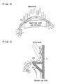
- FIG. 5 is a perspective view of a tower wall surface portion of a portion at which the trough 23 is installed at the absorbing tower gas entrance 3 as viewed from an inner side of the tower.
- the absorbing tower gas entrance 3 is a portion at which gas of a high gas flow velocity flows in, and due to collision with a large group of dropping absorbing liquid droplets, the pressure loss of the exhaust gas flow tends to be large.
- the nose 22 shown in FIG. 3 is protruded at an upper portion of the absorbing tower gas entrance 3
- the rescattered absorbing liquid forms a liquid film at the absorbing tower gas entrance 3 and increases the pressure loss of the exhaust gas flow.
- FIG. 6 shows an example where a supporting plate 24 that guides the exhaust gas toward the tower center is disposed below the nose 22.
- the structure is not restricted in particular as long as the shape enables the absorbing liquid to be rescattered to the absorbing tower center.
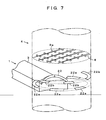
- FIG. 7 shows another embodiment of the present invention.
- the horseshoe-shaped nose 22 is divided into a plurality of portions that are installed in a stepped manner in two stages along a horizontal plane. Because nose pieces 22a of a lower stage and nose pieces 22b of an upper stage are discontinuous at the respective stage, the absorbing liquid that is rescattered by the nose pieces 22a and 22b do not become a uniform liquid film in a horizontal section inside the absorbing tower and an increase in pressure loss can thus be prevented.
- the present invention is high in industrial applicability as a wet-type desulfurization apparatus that enables an absorbing tower to be made compact while preventing an increase in pressure loss of gas flow inside the absorbing tower and a lowering of desulfurization performance due to gas drift.
Landscapes
- Chemical & Material Sciences (AREA)
- Engineering & Computer Science (AREA)
- Analytical Chemistry (AREA)
- General Chemical & Material Sciences (AREA)
- Oil, Petroleum & Natural Gas (AREA)
- Chemical Kinetics & Catalysis (AREA)
- Health & Medical Sciences (AREA)
- Biomedical Technology (AREA)
- Environmental & Geological Engineering (AREA)
- Treating Waste Gases (AREA)
- Gas Separation By Absorption (AREA)
Claims (6)
- Appareil de désulfuration d'échappement de type humide permettant de purifier un gaz d'échappement de combustion de combustibles (1) émis à partir d'un appareil de combustion, ledit appareil de désulfuration d'échappement de type humide comprenant une tour d'absorption (4) pourvue :d'une entrée de gaz (3) disposée au niveau de la paroi latérale de la tour d'absorption (4) pour introduire le gaz d'échappement de combustion de combustibles (1) ;de têtes de pulvérisation (8) disposées en plusieurs étages dans une direction d'écoulement de gaz pour pulvériser un liquide d'absorption, contenant du calcaire ou de l'hydroxyde de calcium, sur le gaz d'échappement (1) ascendant lorsqu'il est introduit à partir de l'entrée de gaz (3) ; etd'un nez (22) s'étendant dans la tour d'absorption (4) et disposé au niveau d'une partie de paroi latérale de tour de la tour d'absorption (4) de sorte que le liquide d'absorption s'écoulant le long de la paroi de tour soit redispersé vers une partie centrale de la tour d'absorption (4),caractérisé en ce queune goulotte (23) est disposée au niveau d'une partie de paroi latérale de tour de la tour d'absorption (4) au niveau d'une partie supérieure de l'entrée de gaz (3) de la tour d'absorption (4) de sorte que la formation d'un film liquide du liquide d'absorption en face de l'entrée de gaz (3) soit empêchée, etle nez (22) a une forme de fer à cheval selon une vue en plan de dessus et est disposé au niveau d'une partie de paroi latérale de tour à l'exception de la partie de paroi latérale de tour au niveau de laquelle la goulotte (23) est disposée à l'entrée de gaz (3) et à la même hauteur ou essentiellement à la même hauteur que la partie de paroi latérale de tour au niveau de laquelle la goulotte (23) est disposée.
- Appareil de désulfuration d'échappement de type humide selon la revendication 1, dans lequel une plage d'installation de la goulotte (23) au niveau de la partie supérieure de l'entrée de gaz (3) de la tour d'absorption (4) est réglée à 90 à 180 degrés dans une direction horizontale et centrée sur une ligne d'axe vertical hypothétique d'une partie centrale de tour, et une plage d'installation du nez (22) est réglée à 190 à 280 degrés dans la direction horizontale et centrée sur la ligne d'axe vertical hypothétique.
- Appareil de désulfuration d'échappement de type humide selon la revendication 1 ou 2, dans lequel une longueur d'extension du nez (22) dans la direction du centre de tour au niveau de la partie à l'exception de l'entrée de gaz (3) et de la goulotte (23) au niveau de la partie supérieure de l'entrée de gaz (3) de la tour d'absorption (4) est réglée dans une plage allant de 100 à 500mm.
- Appareil de désulfuration d'échappement de type humide selon l'une des revendications 1 à 3, dans lequel une position de l'installation du nez (22) se trouve au niveau d'une surface de paroi de tour à une position en-dessous de la tête de pulvérisation (8) de l'étage le plus bas.
- Appareil de désulfuration d'échappement de type humide selon l'une des revendications 1 à 3, dans lequel une position d'installation du nez (22) est réglée au niveau d'une surface de paroi latérale de tour à l'opposé de l'entrée de gaz (3) de la tour d'absorption (4) et entre la tête de pulvérisation (8) de l'étage le plus bas et la tête de pulvérisation (8) d'un étage disposé de manière adjacente au-dessus de l'étage le plus bas.
- Appareil de désulfuration d'échappement de type humide selon l'une des revendications 1 à 5, dans lequel le nez (22) est configuré en tant que nez (22a, 22b) disposés sur la paroi latérale de tour d'une manière qui est étagée dans la direction verticale afin de ne pas se chevaucher dans la direction verticale.
Priority Applications (1)
| Application Number | Priority Date | Filing Date | Title |
|---|---|---|---|
| PL07828263T PL2065083T3 (pl) | 2006-09-19 | 2007-09-19 | Aparat typu mokrego do odsiarczania spalin |
Applications Claiming Priority (2)
| Application Number | Priority Date | Filing Date | Title |
|---|---|---|---|
| JP2006252153 | 2006-09-19 | ||
| PCT/JP2007/068168 WO2008035703A1 (fr) | 2006-09-19 | 2007-09-19 | Appareil de désulfuration d'echappement de type humide |
Publications (3)
| Publication Number | Publication Date |
|---|---|
| EP2065083A1 EP2065083A1 (fr) | 2009-06-03 |
| EP2065083A4 EP2065083A4 (fr) | 2010-11-10 |
| EP2065083B1 true EP2065083B1 (fr) | 2014-04-09 |
Family
ID=39200528
Family Applications (1)
| Application Number | Title | Priority Date | Filing Date |
|---|---|---|---|
| EP07828263.9A Active EP2065083B1 (fr) | 2006-09-19 | 2007-09-19 | Appareil de désulfuration d'echappement de type humide |
Country Status (5)
| Country | Link |
|---|---|
| US (1) | US8172931B2 (fr) |
| EP (1) | EP2065083B1 (fr) |
| JP (1) | JP5234783B2 (fr) |
| PL (1) | PL2065083T3 (fr) |
| WO (1) | WO2008035703A1 (fr) |
Families Citing this family (11)
| Publication number | Priority date | Publication date | Assignee | Title |
|---|---|---|---|---|
| CN101511446B (zh) * | 2006-07-26 | 2012-05-02 | 巴布考克日立株式会社 | 排气中微量有害物质的除去装置和其运行方法 |
| PL2361667T3 (pl) * | 2010-02-25 | 2015-07-31 | General Electric Technology Gmbh | Płuczka wodna i sposób oczyszczania gazu procesowego |
| JP5725725B2 (ja) * | 2010-04-07 | 2015-05-27 | 三菱日立パワーシステムズ株式会社 | 湿式排煙脱硫装置 |
| US10375901B2 (en) | 2014-12-09 | 2019-08-13 | Mtd Products Inc | Blower/vacuum |
| JP5979269B1 (ja) * | 2015-03-16 | 2016-08-24 | 富士電機株式会社 | 排ガス処理装置 |
| CN106422639B (zh) * | 2016-12-07 | 2020-02-14 | 北京中能诺泰节能环保技术有限责任公司 | 除尘脱硫增效器及湿法脱硫装置 |
| CN107569983B (zh) * | 2017-08-08 | 2020-04-03 | 武汉和尔环保科技有限公司 | 烟气湿法脱硫设备 |
| WO2019150432A1 (fr) * | 2018-01-30 | 2019-08-08 | 三菱日立パワーシステムズ株式会社 | Système de désulfuration |
| CN110527564A (zh) * | 2019-08-08 | 2019-12-03 | 佰利天控制设备(北京)有限公司 | 高炉煤气脱硫塔 |
| CN111644044B (zh) * | 2020-05-29 | 2022-03-01 | 莱芜金山矿产资源有限公司 | 废气脱硫净化系统及废气净化方法 |
| CN116808813B (zh) * | 2023-07-25 | 2024-01-30 | 江苏永纪实业集团有限公司 | 一种低成本的湿法脱硝设备及脱硝工艺 |
Family Cites Families (9)
| Publication number | Priority date | Publication date | Assignee | Title |
|---|---|---|---|---|
| GB493446A (en) * | 1937-04-05 | 1938-10-05 | Henry Edward Byer | Improvements in or relating to method of and apparatus for treating gases with liquids |
| US3907526A (en) * | 1973-04-30 | 1975-09-23 | Peabody Engineering Corp | High velocity spray scrubber |
| JPS61185316A (ja) | 1985-02-13 | 1986-08-19 | Babcock Hitachi Kk | 湿式排煙脱硫装置 |
| JPH05293333A (ja) | 1991-08-09 | 1993-11-09 | Babcock Hitachi Kk | 湿式排煙脱硫装置 |
| GB9226129D0 (en) * | 1992-12-15 | 1993-02-10 | Baker Salah A | A process vessel |
| JP3968830B2 (ja) * | 1997-07-24 | 2007-08-29 | 石川島播磨重工業株式会社 | 排煙脱硫装置の吸収塔 |
| US6550751B1 (en) | 1997-11-26 | 2003-04-22 | Marsulex Environmental Technologies Corp. | Gas-liquid contactor with liquid redistribution device |
| JP2001327831A (ja) * | 2000-05-24 | 2001-11-27 | Babcock Hitachi Kk | 湿式排ガス脱硫装置 |
| JP3776793B2 (ja) * | 2001-12-14 | 2006-05-17 | バブコック日立株式会社 | 湿式排煙脱硫装置 |
-
2007
- 2007-09-19 EP EP07828263.9A patent/EP2065083B1/fr active Active
- 2007-09-19 US US12/441,648 patent/US8172931B2/en active Active
- 2007-09-19 WO PCT/JP2007/068168 patent/WO2008035703A1/fr active Application Filing
- 2007-09-19 PL PL07828263T patent/PL2065083T3/pl unknown
- 2007-09-19 JP JP2008535370A patent/JP5234783B2/ja not_active Expired - Fee Related
Also Published As
| Publication number | Publication date |
|---|---|
| JP5234783B2 (ja) | 2013-07-10 |
| EP2065083A1 (fr) | 2009-06-03 |
| EP2065083A4 (fr) | 2010-11-10 |
| PL2065083T3 (pl) | 2014-09-30 |
| US20090320687A1 (en) | 2009-12-31 |
| WO2008035703A1 (fr) | 2008-03-27 |
| US8172931B2 (en) | 2012-05-08 |
| JPWO2008035703A1 (ja) | 2010-01-28 |
Similar Documents
| Publication | Publication Date | Title |
|---|---|---|
| EP2065083B1 (fr) | Appareil de désulfuration d'echappement de type humide | |
| US5512072A (en) | Flue gas scrubbing apparatus | |
| US8092582B2 (en) | Wet-type exhaust gas desulfurizer | |
| US8496742B2 (en) | Wet flue-gas desulfurization equipment | |
| US7976622B2 (en) | Wet flue gas desulfurization apparatus | |
| CA2384872C (fr) | Technique de lavage des gaz de combustion avec emploi de contracteur gaz-liquide | |
| EP2826541B1 (fr) | Système de buse d'épurateur humide et procédé d'utilisation pour le nettoyage d'un gaz de traitement | |
| EP2265357B1 (fr) | Systèmes et procédés pour éliminer des polluants gazeux à partir d'un courant de gaz | |
| EP1958682A1 (fr) | Appareil et procede humides de desulfuration des gaz de combustion | |
| US20120189522A1 (en) | Method of Desulfurizing Flue Gas, an Arrangement for Desulfurizing Flue Gas, and a Method of Modernizing a Desulfurization Arrangement | |
| KR101473285B1 (ko) | 습식 배연 탈류 장치 | |
| EP3302759B1 (fr) | Épurateur de gaz à niveaux multiples doté de multiples têtes d'épurateur noyées | |
| JP2001523563A (ja) | 液再分配装置を備えた気液接触器 | |
| KR20150070110A (ko) | 연도 가스 정화장치 | |
| US10603624B2 (en) | Wet flue gas desulfurization process and apparatus | |
| CN104607009A (zh) | 烟气除尘脱硫塔及烟气脱硫方法 | |
| CN104607010A (zh) | 一种烟气除尘脱硫塔及烟气脱硫方法 | |
| JP5289668B2 (ja) | 湿式排煙脱硫装置 | |
| CN108404640A (zh) | 一种烟气脱硫脱硝一体化装置及方法 | |
| JPH07155536A (ja) | 湿式排煙脱硫装置 | |
| JP2003103139A (ja) | 湿式排煙脱硫装置 | |
| CN201768484U (zh) | 双向气-液式锅炉烟气净化装置 | |
| CN110124496A (zh) | 一种双循环脱硫工艺方法 | |
| CN110449009A (zh) | 一种废气处理用的喷淋塔 | |
| CN219111287U (zh) | 一种脱硫塔 |
Legal Events
| Date | Code | Title | Description |
|---|---|---|---|
| PUAI | Public reference made under article 153(3) epc to a published international application that has entered the european phase |
Free format text: ORIGINAL CODE: 0009012 |
|
| 17P | Request for examination filed |
Effective date: 20090317 |
|
| AK | Designated contracting states |
Kind code of ref document: A1 Designated state(s): AT BE BG CH CY CZ DE DK EE ES FI FR GB GR HU IE IS IT LI LT LU LV MC MT NL PL PT RO SE SI SK TR |
|
| AX | Request for extension of the european patent |
Extension state: AL BA HR MK RS |
|
| A4 | Supplementary search report drawn up and despatched |
Effective date: 20101012 |
|
| DAX | Request for extension of the european patent (deleted) | ||
| GRAP | Despatch of communication of intention to grant a patent |
Free format text: ORIGINAL CODE: EPIDOSNIGR1 |
|
| INTG | Intention to grant announced |
Effective date: 20130411 |
|
| GRAP | Despatch of communication of intention to grant a patent |
Free format text: ORIGINAL CODE: EPIDOSNIGR1 |
|
| INTG | Intention to grant announced |
Effective date: 20131127 |
|
| GRAS | Grant fee paid |
Free format text: ORIGINAL CODE: EPIDOSNIGR3 |
|
| GRAA | (expected) grant |
Free format text: ORIGINAL CODE: 0009210 |
|
| AK | Designated contracting states |
Kind code of ref document: B1 Designated state(s): AT BE BG CH CY CZ DE DK EE ES FI FR GB GR HU IE IS IT LI LT LU LV MC MT NL PL PT RO SE SI SK TR |
|
| REG | Reference to a national code |
Ref country code: GB Ref legal event code: FG4D |
|
| REG | Reference to a national code |
Ref country code: AT Ref legal event code: REF Ref document number: 661020 Country of ref document: AT Kind code of ref document: T Effective date: 20140415 Ref country code: CH Ref legal event code: EP |
|
| REG | Reference to a national code |
Ref country code: IE Ref legal event code: FG4D |
|
| REG | Reference to a national code |
Ref country code: DE Ref legal event code: R096 Ref document number: 602007036058 Country of ref document: DE Effective date: 20140522 |
|
| RAP2 | Party data changed (patent owner data changed or rights of a patent transferred) |
Owner name: BABCOCK-HITACHI K.K. |
|
| REG | Reference to a national code |
Ref country code: GR Ref legal event code: EP Ref document number: 20140400883 Country of ref document: GR Effective date: 20140625 |
|
| REG | Reference to a national code |
Ref country code: AT Ref legal event code: MK05 Ref document number: 661020 Country of ref document: AT Kind code of ref document: T Effective date: 20140409 |
|
| REG | Reference to a national code |
Ref country code: NL Ref legal event code: VDEP Effective date: 20140409 |
|
| REG | Reference to a national code |
Ref country code: LT Ref legal event code: MG4D |
|
| REG | Reference to a national code |
Ref country code: PL Ref legal event code: T3 |
|
| PG25 | Lapsed in a contracting state [announced via postgrant information from national office to epo] |
Ref country code: IS Free format text: LAPSE BECAUSE OF FAILURE TO SUBMIT A TRANSLATION OF THE DESCRIPTION OR TO PAY THE FEE WITHIN THE PRESCRIBED TIME-LIMIT Effective date: 20140809 Ref country code: NL Free format text: LAPSE BECAUSE OF FAILURE TO SUBMIT A TRANSLATION OF THE DESCRIPTION OR TO PAY THE FEE WITHIN THE PRESCRIBED TIME-LIMIT Effective date: 20140409 Ref country code: LT Free format text: LAPSE BECAUSE OF FAILURE TO SUBMIT A TRANSLATION OF THE DESCRIPTION OR TO PAY THE FEE WITHIN THE PRESCRIBED TIME-LIMIT Effective date: 20140409 Ref country code: BG Free format text: LAPSE BECAUSE OF FAILURE TO SUBMIT A TRANSLATION OF THE DESCRIPTION OR TO PAY THE FEE WITHIN THE PRESCRIBED TIME-LIMIT Effective date: 20140709 Ref country code: FI Free format text: LAPSE BECAUSE OF FAILURE TO SUBMIT A TRANSLATION OF THE DESCRIPTION OR TO PAY THE FEE WITHIN THE PRESCRIBED TIME-LIMIT Effective date: 20140409 |
|
| PG25 | Lapsed in a contracting state [announced via postgrant information from national office to epo] |
Ref country code: AT Free format text: LAPSE BECAUSE OF FAILURE TO SUBMIT A TRANSLATION OF THE DESCRIPTION OR TO PAY THE FEE WITHIN THE PRESCRIBED TIME-LIMIT Effective date: 20140409 Ref country code: LV Free format text: LAPSE BECAUSE OF FAILURE TO SUBMIT A TRANSLATION OF THE DESCRIPTION OR TO PAY THE FEE WITHIN THE PRESCRIBED TIME-LIMIT Effective date: 20140409 Ref country code: SE Free format text: LAPSE BECAUSE OF FAILURE TO SUBMIT A TRANSLATION OF THE DESCRIPTION OR TO PAY THE FEE WITHIN THE PRESCRIBED TIME-LIMIT Effective date: 20140409 Ref country code: ES Free format text: LAPSE BECAUSE OF FAILURE TO SUBMIT A TRANSLATION OF THE DESCRIPTION OR TO PAY THE FEE WITHIN THE PRESCRIBED TIME-LIMIT Effective date: 20140409 |
|
| PG25 | Lapsed in a contracting state [announced via postgrant information from national office to epo] |
Ref country code: PT Free format text: LAPSE BECAUSE OF FAILURE TO SUBMIT A TRANSLATION OF THE DESCRIPTION OR TO PAY THE FEE WITHIN THE PRESCRIBED TIME-LIMIT Effective date: 20140811 |
|
| REG | Reference to a national code |
Ref country code: DE Ref legal event code: R097 Ref document number: 602007036058 Country of ref document: DE |
|
| PG25 | Lapsed in a contracting state [announced via postgrant information from national office to epo] |
Ref country code: CZ Free format text: LAPSE BECAUSE OF FAILURE TO SUBMIT A TRANSLATION OF THE DESCRIPTION OR TO PAY THE FEE WITHIN THE PRESCRIBED TIME-LIMIT Effective date: 20140409 Ref country code: SK Free format text: LAPSE BECAUSE OF FAILURE TO SUBMIT A TRANSLATION OF THE DESCRIPTION OR TO PAY THE FEE WITHIN THE PRESCRIBED TIME-LIMIT Effective date: 20140409 Ref country code: DK Free format text: LAPSE BECAUSE OF FAILURE TO SUBMIT A TRANSLATION OF THE DESCRIPTION OR TO PAY THE FEE WITHIN THE PRESCRIBED TIME-LIMIT Effective date: 20140409 Ref country code: EE Free format text: LAPSE BECAUSE OF FAILURE TO SUBMIT A TRANSLATION OF THE DESCRIPTION OR TO PAY THE FEE WITHIN THE PRESCRIBED TIME-LIMIT Effective date: 20140409 Ref country code: BE Free format text: LAPSE BECAUSE OF FAILURE TO SUBMIT A TRANSLATION OF THE DESCRIPTION OR TO PAY THE FEE WITHIN THE PRESCRIBED TIME-LIMIT Effective date: 20140409 Ref country code: RO Free format text: LAPSE BECAUSE OF FAILURE TO SUBMIT A TRANSLATION OF THE DESCRIPTION OR TO PAY THE FEE WITHIN THE PRESCRIBED TIME-LIMIT Effective date: 20140409 |
|
| PLBE | No opposition filed within time limit |
Free format text: ORIGINAL CODE: 0009261 |
|
| STAA | Information on the status of an ep patent application or granted ep patent |
Free format text: STATUS: NO OPPOSITION FILED WITHIN TIME LIMIT |
|
| REG | Reference to a national code |
Ref country code: DE Ref legal event code: R082 Ref document number: 602007036058 Country of ref document: DE Representative=s name: TBK, DE |
|
| 26N | No opposition filed |
Effective date: 20150112 |
|
| PG25 | Lapsed in a contracting state [announced via postgrant information from national office to epo] |
Ref country code: IT Free format text: LAPSE BECAUSE OF FAILURE TO SUBMIT A TRANSLATION OF THE DESCRIPTION OR TO PAY THE FEE WITHIN THE PRESCRIBED TIME-LIMIT Effective date: 20140409 |
|
| REG | Reference to a national code |
Ref country code: DE Ref legal event code: R081 Ref document number: 602007036058 Country of ref document: DE Owner name: MITSUBISHI HITACHI POWER SYSTEMS, LTD., YOKOHA, JP Free format text: FORMER OWNER: BABCOCK-HITACHI K.K., TOKYO, JP Effective date: 20150305 Ref country code: DE Ref legal event code: R082 Ref document number: 602007036058 Country of ref document: DE Representative=s name: TBK, DE Effective date: 20150305 |
|
| REG | Reference to a national code |
Ref country code: DE Ref legal event code: R097 Ref document number: 602007036058 Country of ref document: DE Effective date: 20150112 |
|
| PG25 | Lapsed in a contracting state [announced via postgrant information from national office to epo] |
Ref country code: LU Free format text: LAPSE BECAUSE OF FAILURE TO SUBMIT A TRANSLATION OF THE DESCRIPTION OR TO PAY THE FEE WITHIN THE PRESCRIBED TIME-LIMIT Effective date: 20140919 Ref country code: MC Free format text: LAPSE BECAUSE OF FAILURE TO SUBMIT A TRANSLATION OF THE DESCRIPTION OR TO PAY THE FEE WITHIN THE PRESCRIBED TIME-LIMIT Effective date: 20140409 |
|
| REG | Reference to a national code |
Ref country code: CH Ref legal event code: PL |
|
| GBPC | Gb: european patent ceased through non-payment of renewal fee |
Effective date: 20140919 |
|
| REG | Reference to a national code |
Ref country code: IE Ref legal event code: MM4A |
|
| REG | Reference to a national code |
Ref country code: FR Ref legal event code: ST Effective date: 20150529 |
|
| PG25 | Lapsed in a contracting state [announced via postgrant information from national office to epo] |
Ref country code: CH Free format text: LAPSE BECAUSE OF NON-PAYMENT OF DUE FEES Effective date: 20140930 Ref country code: SI Free format text: LAPSE BECAUSE OF FAILURE TO SUBMIT A TRANSLATION OF THE DESCRIPTION OR TO PAY THE FEE WITHIN THE PRESCRIBED TIME-LIMIT Effective date: 20140409 Ref country code: LI Free format text: LAPSE BECAUSE OF NON-PAYMENT OF DUE FEES Effective date: 20140930 Ref country code: GB Free format text: LAPSE BECAUSE OF NON-PAYMENT OF DUE FEES Effective date: 20140919 |
|
| PG25 | Lapsed in a contracting state [announced via postgrant information from national office to epo] |
Ref country code: FR Free format text: LAPSE BECAUSE OF NON-PAYMENT OF DUE FEES Effective date: 20140930 Ref country code: IE Free format text: LAPSE BECAUSE OF NON-PAYMENT OF DUE FEES Effective date: 20140919 |
|
| PG25 | Lapsed in a contracting state [announced via postgrant information from national office to epo] |
Ref country code: CY Free format text: LAPSE BECAUSE OF FAILURE TO SUBMIT A TRANSLATION OF THE DESCRIPTION OR TO PAY THE FEE WITHIN THE PRESCRIBED TIME-LIMIT Effective date: 20140409 Ref country code: MT Free format text: LAPSE BECAUSE OF FAILURE TO SUBMIT A TRANSLATION OF THE DESCRIPTION OR TO PAY THE FEE WITHIN THE PRESCRIBED TIME-LIMIT Effective date: 20140409 |
|
| PG25 | Lapsed in a contracting state [announced via postgrant information from national office to epo] |
Ref country code: HU Free format text: LAPSE BECAUSE OF FAILURE TO SUBMIT A TRANSLATION OF THE DESCRIPTION OR TO PAY THE FEE WITHIN THE PRESCRIBED TIME-LIMIT; INVALID AB INITIO Effective date: 20070919 Ref country code: TR Free format text: LAPSE BECAUSE OF FAILURE TO SUBMIT A TRANSLATION OF THE DESCRIPTION OR TO PAY THE FEE WITHIN THE PRESCRIBED TIME-LIMIT Effective date: 20140409 |
|
| REG | Reference to a national code |
Ref country code: DE Ref legal event code: R082 Ref document number: 602007036058 Country of ref document: DE Representative=s name: TBK, DE Ref country code: DE Ref legal event code: R081 Ref document number: 602007036058 Country of ref document: DE Owner name: MITSUBISHI POWER, LTD., JP Free format text: FORMER OWNER: MITSUBISHI HITACHI POWER SYSTEMS, LTD., YOKOHAMA, KANAGAWA, JP |
|
| PGFP | Annual fee paid to national office [announced via postgrant information from national office to epo] |
Ref country code: GR Payment date: 20210811 Year of fee payment: 15 Ref country code: PL Payment date: 20210813 Year of fee payment: 15 Ref country code: DE Payment date: 20210810 Year of fee payment: 15 |
|
| REG | Reference to a national code |
Ref country code: DE Ref legal event code: R119 Ref document number: 602007036058 Country of ref document: DE |
|
| PG25 | Lapsed in a contracting state [announced via postgrant information from national office to epo] |
Ref country code: DE Free format text: LAPSE BECAUSE OF NON-PAYMENT OF DUE FEES Effective date: 20230401 |
|
| PG25 | Lapsed in a contracting state [announced via postgrant information from national office to epo] |
Ref country code: GR Free format text: LAPSE BECAUSE OF NON-PAYMENT OF DUE FEES Effective date: 20230406 |