EP2064027B1 - Smart probe - Google Patents
Smart probe Download PDFInfo
- Publication number
- EP2064027B1 EP2064027B1 EP07837679.5A EP07837679A EP2064027B1 EP 2064027 B1 EP2064027 B1 EP 2064027B1 EP 07837679 A EP07837679 A EP 07837679A EP 2064027 B1 EP2064027 B1 EP 2064027B1
- Authority
- EP
- European Patent Office
- Prior art keywords
- probe
- smart
- removable
- arm
- coordinate
- Prior art date
- Legal status (The legal status is an assumption and is not a legal conclusion. Google has not performed a legal analysis and makes no representation as to the accuracy of the status listed.)
- Not-in-force
Links
Images


Classifications
-
- G—PHYSICS
- G01—MEASURING; TESTING
- G01B—MEASURING LENGTH, THICKNESS OR SIMILAR LINEAR DIMENSIONS; MEASURING ANGLES; MEASURING AREAS; MEASURING IRREGULARITIES OF SURFACES OR CONTOURS
- G01B5/00—Measuring arrangements characterised by the use of mechanical techniques
- G01B5/004—Measuring arrangements characterised by the use of mechanical techniques for measuring coordinates of points
- G01B5/008—Measuring arrangements characterised by the use of mechanical techniques for measuring coordinates of points using coordinate measuring machines
- G01B5/012—Contact-making feeler heads therefor
-
- G—PHYSICS
- G01—MEASURING; TESTING
- G01B—MEASURING LENGTH, THICKNESS OR SIMILAR LINEAR DIMENSIONS; MEASURING ANGLES; MEASURING AREAS; MEASURING IRREGULARITIES OF SURFACES OR CONTOURS
- G01B5/00—Measuring arrangements characterised by the use of mechanical techniques
- G01B5/004—Measuring arrangements characterised by the use of mechanical techniques for measuring coordinates of points
- G01B5/008—Measuring arrangements characterised by the use of mechanical techniques for measuring coordinates of points using coordinate measuring machines
Definitions
- the present invention relates in general to measurement devices and methods including, but not limited to, coordinate measurement machines (CMM's).
- CCM's coordinate measurement machines
- Coordinate measurement machines measure parts, typically during manufacture, by probing the part to be measured with a probe such as a probe tip either by physical contact of the probe tip to the part, or by non-contact means.
- Angular encoders or other means may be located in the joints of the CMM robotic arm segments which hold the probe tip, and thus the position of the probe tip may be measured in a convenient coordinate system of the user's choosing.
- the operations of the CMM can also be coordinated with a CAD system or software for example.
- probes or end effectors are used for different applications. For example, some areas of an object to be measured are difficult to reach and thus require specifically sized or shaped probes to be used on the CMM. Therefore, probes are commonly interchanged depending upon the characteristics of the region to be measured.
- An example of a current system in use is the Romer Simcor "Infinite" series that uses a specific pin system associated with each specific interchangeable probe.
- a set of specific probes can be interchanged and identified by the CMM using a physical and /or electrical pin orientation which is unique to each probe and which must be entered and stored into a memory located in the CMM for example for later recognition.
- the number of probes that are useable is limited by the possible pin orientations.
- probes of the same size/type cannot be distinguished.
- a manual initial set-up and entry to a memory in the CMM for example is needed to record the dimensions and characteristics of each specific end effector in a useable database.
- the system is limited in scope of application, and it is not a fully automatic recognition system or a readily, easily, or infinitely expandable system. It is also not dynamically configurable or configurable on the fly during measurement. For example, if a particular algorithm or particular data is used with the probe, since the Romer probe does not have a processor or a memory, the algorithms or data used with the probe could not be easily updated in the probe itself.
- US 2004/0185706 , US 2005/0166413 and US6,487,896 dislcose probes with probe calibration or identification data stored on the probes.
- the present system, method, article of manufacture, and apparatus is an "intelligent" probe system and may comprise, in at least an embodiment, an embedded IC chip located in an interchangeable probe(s) which offers repeatable, fast, easy, and error free probe swapping on a CMM.
- an interchangeable probe located in an interchangeable probe(s) which offers repeatable, fast, easy, and error free probe swapping on a CMM.
- Fig. 1 is a front perspective view of a CMM with an articulated arm and an attached computer;
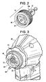
- Fig. 2 is rear perspective view of an interchangeable probe with an embedded integrated circuit
- Fig. 3 is front perspective view of an attachment point for the interchangeable probe on the CMM
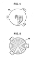
- Fig. 4 is a top view of a concentric ring commutator of the second embodiment
- Fig. 5 is a bottom view of a concentric ring commutator of the second embodiment
- Fig. 6 is a perspective view of a connector having a concentric ring commutator of the second embodiment
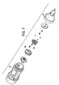
- Fig. 7 is an exploded view of a probe body with a connector having a concentric ring commutator of the second embodiment
- Fig. 8 is an exploded view of a probe body with a connector having a concentric ring commutator of the second embodiment
- Fig. 9 is a sectional view of a probe body with a connector having a concentric ring commutator of the second embodiment
- Fig. 10 is a sectional view of a probe body with a connector having a concentric ring commutator of the second embodiment
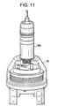
- Fig. 11 is a sectional view of a probe body with a connector having a concentric ring commutator of the second embodiment.
- Fig. 12 is a perspective view of a probe body with a wireless connector of a third embodiment.
- Fig. 13 is a sectional view of a CMM arm with a wireless connector of a third embodiment.
- Fig. 14 shows a screen shot of one embodiment of software that may be associated with the present system
- a CMM 30 is generally shown in Figure 1 .
- an example of the present system is an "intelligent" probe system comprising an embedded IC chip 15 located in an interchangeable probe(s) 10 which offers repeatable, fast, easy, and error free probe swapping on the CMM 30 as each probe 10 is "electronically serialized" with the embedded IC chip 15 and an electronic serial number.
- the IC chip 15 also contains a memory buffer that stores the probe's attributes, information specific to the characteristics of the probe, and calibration data specific to a CMM.
- the IC chip 15 it also possible for the IC chip 15 to be located in an adapter probe body 10 which would be attached between a standard "dumb" probe tip10a and a CMM arm 20. Therefore, the specific location of the IC chip is not limited and may be placed anywhere in examples.
- the embedded IC chip 15 when attached onto the CMM arm 20, the embedded IC chip 15 not only identifies the size and type of probe 10, but it ties a specific set of calibration data to a combination of probe 10 and CMM arm 20 for example.
- the same probe 10 may be used on multiple CMM arms 20, and each calibration set will be unique for a particular serial numbered probe/arm combination thus ensuring maximum accuracy.
- Calibration data may be created via a probe calibration at any time. This new data will be saved on and will remain with the CMM arm 20, or be saved in a memory in the IC chip 15 on the probe 10 depending upon the application. Each arm can retain data for multiple probes, or all the necessary data can be stored in the probe if desired.
- Calibration data and probe data or information to be transferred from for example an EEPROM IC CHIP 15 (located somewhere in the probe or remotely) to make the system "smart,” may include, but is not limited to, tip diameter, coefficient of thermal expansion (CTE), probe type (for example hard probe or mechanical touch probe or other type), ball diameter, and "x, y, z, offsets" and/or six degrees of freedom for the probe either by itself and/or when it is connected to a particular CMM and may be dependent upon the individual configuration and programming. This can all be indexed to a serial number for example and/or any data format may be used. Thus, when the smart probe 10 is connected to the CMM arm 20 all of the necessary calibration and probe data is automatically transferred.
- CTE coefficient of thermal expansion
- probe type for example hard probe or mechanical touch probe or other type
- ball diameter ball diameter
- x, y, z, offsets and/or six degrees of freedom for the probe either by itself and/or when it is connected to a particular CMM and may be dependent upon
- Figure 14 shows a screen shot of one embodiment of software associated with the present system wherein the probe's serial number is read and then indicates the tip diameter to be 6 mm, and the temperature coefficient of thermal expansion (CTE) to be 1.0 e-009 for example.
- CTE temperature coefficient of thermal expansion
- any relevant data fields may be configured to be read based on the user's preferences and the configurations and thus the invention is not limited to the configuration shown in this screen shot.
- a calibration ball, a hole, or artifact may be measured by the system to perform an arm calibration or other calibration as well and these calibration methods are well known in robotics and thus not discussed further herein.
- Probes 10 may take many additional and different shapes and forms as needed (not shown). However, using the present "smart probe" system, the probes 10 may be changed at any time without performing another probe calibration. Specifically, upon mating with electrical connection section 40 having any desired orientation of electrical contacts 60, the probe 10 serial number will automatically be detected and proper calibration data will be called by the system computer 50 or other suitable means, and used by CAM Measure software for example for operation of the CMM 3 0. No menu selection of probes will be required so long as electronically serialized probes are used. Thus, the probe is automatically recognized or installed and the CMM arm 20 and probe 10 combination is automatically calibrated in a "plug and play” fashion as the system uses the serial number to reference calibration data specific to the probe and correlates that to the operational kinematics.
- connection structures are encompassed by and will be suitable for use with the present invention.
- connection structures are not limited in any way by the below description of embodiments.
- a three ball 70 kinematic mount connection structure with pin 80 is shown.
- pin 80 is slid into hole 81 to align the electrical contacts 60 and then a rotatable threaded ring 85 is screwed down to hold the probe 10 onto electrical connection section 40 of the CMM arm 20.
- IC chip 15 is shown within probe tip 10a simply for convenience. However, often times probe tip 10a may be a "dumb” probe tip supplied by any “dumb” probe tip manufacturer. The dumb probe tip 10a is then simply connected to a probe 10 that would contain a programmable IC chip 15 (not shown) is this case. The IC chip would have to be initially programmed with the properties and dimensions of the dumb probe body 10a, but after this is done, a smart probe 10 (with the dumb probe body attached) has been effectively created. Thus, probe 10 is more like an "adapter” in this case because any dumb probe made by anyone can be attached to probe 10. Figure 10 shows this very clearly in one embodiment wherein "smart" probe 10 accepts the threaded dumb probe tip 10a.
- a second embodiment connection structure is shown.
- a "screw on" probe is used to make the electrical connection between electrical contacts and a concentric ring commutator 100.
- the probe 10 is simply screwed onto the CMM arm 20.
- This version also has four electrical contacts.
- the probe 10 may be "dynamically configurable" so that any stored programs, calibrations, software, data, algorithms or other information can be easily updated or changed. For example, if particular data is used with the probe, since probe 10 has embedded IC chip 15 with a memory capability for example, the data used with the probe may be easily updated in the probe. Alternatively, the updated data could be present in the computer 50 or other means in the CMM 30 and then probe 10 and IC chip 15 could be updated when it is connected to the CMM arm 20. This offers an enormous time savings and flexibility over the "dumb probes" of the prior art.
- a serialized probe 10 is attached to a CMM arm 20 where no prior calibration data has been collected, the user will be required to perform a probe calibration. The data will be saved in any desired location including in the probe 10 for example, and the probe calibration for this arm/probe combination will not be required again.
- probes may be changed at any time without performing another probe calibration.
- calibration data is specific to an arm-probe combination, the same probe may be used on multiple arms. Each calibration data set will be unique for a particular serial numbered probe/arm combination thus ensuring maximum accuracy.
- Calibration data may be created via a probe calibration at any time. This new data may be saved on and will remain with the arm, or within the probe itself.
- any probe calibration will be simplified because known or fixed variables such as the probe tip diameter, and the probe length will already be fixed and known and thus these variables will not have to be computed or measured in the probe calibration.
- Each CMM arm 20 may also retain data for any probe that has been calibrated on it and which may be viewed or updated on display terminal 50.
- a database (not shown) may also be present in the CMM 20 or may be located in remote location and may be accessible by wireless or other means.
- RenishawTM probes using contact switch technology are obvious types of alternate configurations that will benefit from the technology.
- Specific contact directions that affect the probe performance can be stored inside the IC, thus improving accuracy and performance of the system.
- the present system may also be used with and to improve the systems disclosed in U.S. patents 6,931,745 , 5,829,148 and 6,920,697 and many other CMM's and measurement systems for example.
- the system may also periodically interrogate the probe 10 for presence to ensure it has not been removed or changed and thereby maintain integrity the system and each measurement.
- Software may configure the operation of the CMM arm 20 to use a probe without the present smart probe 10 system.
- the probe must be calibrated before use and there is no way for the system to detect when a probe has been changed, which is common source of error.
- software can automatically configure the operation of the application whenever the present smart probe 10 is attached.
- the probe 10 may be mounted on the CMM 30 or other measurement device by the means of a kinematic mount.
- the kinematic mount ensures that the probe is installed exactly the way it was during initial calibration.
- the kinematic mount may comprise three equally spaced balls mounted on the measurement device and three tapered slots in the probe 10.
- a pin 80 is used to ensure that the three balls 70 always return to the same slots they were in during initial calibration.
- the scope of a smart probe 10 is expanded to include the provision of more sophisticated probes.
- the intelligence embedded in the end effector will include parametrics for not only the probe type and attributes, it includes the ability to store attribute data for articulators. Use with different systems, is a learning process that once used, will not have to be taught the information again.
- the probe 10 is a true "plug and play" type of probe.
- the probe itself is not limited to hard contact effectors, but active and dynamic sensors, and the complexity of multiple sensors.
- a temperature sensor could be easily embedded into the contactor to measure artifact temperature and render isotherm profiles.
- the same temperature sensor probe could easily identify to the system, when a surface is contacted and report the point at contact.
- Other sensor types are conceived as physical transducers for pressure, resistive, capacitive, optical, magnetic, electromagnetic, radio and sonic sensing means.
- a part temperature measurement system may be added to the CMM arm.
- This could be an I/R, non-contact temperature measurement system built into the end of the arm or into a probe or other arrangement, or a fast response temperature sensor in the probe tip that could measure a part temperature with a few milliseconds of touching the part.
- it is envisioned to collect temperature data, not only of the part, but of the section of the part being measured. This temperature data would be linked to the measurement data in real time for later analysis with the intent of generating a temperature profile of the part in CAD, and/or providing data for temperature compensation of the measurement data.
- large equipment companies sometimes measure parts (like an airplane wing) that are part in sun and part in shade.
- a set of data may be taken over several hours as temperatures change.
- a temperature profile could be constructed and used to compensate measurements.
- the temperature measurement device may be integrated into the arm, and collects both temperature data and measurement data simultaneously.
- part temperature is measured, it is usually done with a separate piece of equipment at a single point in time.
- wireless technologies shown by "W" in the figures may also be used between any of the parts of the CMM, such as between the probe tip 10a, probe body 20, and the CMM 20 or between the CMM and a laptop computer or anywhere that wires are desired to be eliminated.
- Some of the common wireless standards are discussed below, however any appropriate wireless standard or radio frequency may be used.
- RFID may be a possible wireless "smart probe" implementation.
- RFID Radio-frequency identification
- RFID tags are an automatic identification method, relying on storing and remotely retrieving data using devices called RFID tags or transponders.
- An RFID tag is an object that can be stuck on or incorporated into a product, animal, or person for the purpose of identification using radiowaves. Some tags can be read from several meters away and beyond the line of sight of the reader.
- RFID tags contain at least two parts. One is an integrated circuit for storing and processing information, modulating and demodulating a (RF) signal and can also be used for other specialized functions. The second is an antenna for receiving and transmitting the signal.
- RF radio frequency
- 802.11 refers to a family of specifications developed by the IEEE for wireless LAN technology
- 802.11 specifies an over-the-air interface between a wireless client and a base station or between two wireless clients.
- 802.11 applies to wireless LANs and provides 1 or 2 Mbps transmission in the 2.4 GHz band using either frequency hopping spread spectrum (FHSS) or direct sequence spread spectrum (DSSS).
- FHSS frequency hopping spread spectrum
- DSSS direct sequence spread spectrum
- 802.11 a - - an extension to 802.11 that applies to wireless LANs and provides up to 54 Mbps in the 5GHz band.
- 802.11a uses an orthogonal frequency division multiplexing encoding scheme rather than FHSS or DSSS.
- 802.11 b (also referred to as 802.11 High Rate or Wi-Fi -- an extension to 802.11 that applies to wireless LANS and provides 11 Mbps transmission (with a fallback to 5.5,2 and 1 Mbps) in the 2.4 GHz band. 802.11b uses only DSSS. 802.11b was a 1999 ratification to the original 802.11 standard, allowing wireless functionality comparable to Ethernet.
- 802.11 g applies to wireless LANs and provides 54 Mbps in the 2.4 GHz band.
- 802.11 g specification employs orthogonal frequency division multiplexing (OFDM), the modulation scheme used in 802.11a to obtain higher data speed.
- Computers or terminals set up for 802.11g can fall back to speeds of 11 Mbps. This feature makes 802.11b and 802.11g devices compatible within a single network.
- OFDM orthogonal frequency division multiplexing
- 802.11 g is the most widely and commonly available technology.
- 802.15 is a communications specification that was approved in early 2002 by the Institute of Electrical and Electronics Engineers Standards Association (IEEE-SA) for wireless personal area networks (WPANs).
- IEEE-SA Institute of Electrical and Electronics Engineers Standards Association
- the IEEE 802.15 Working Group proposed two general categories of 802.15, called TG4 (low rate) and TG3 (high rate).
- the TG4 version provides data speeds of 20 Kbps or 250 Kbps.
- the TG3 version supports data speeds ranging from 1.1 Mbps to 55 Mbps.
- ZigBee falls into the TG4 group while Bluetooth the TG3. ZigBee plays a major role for remote sensors.
- Bluetooth is a short-range, radio-based wireless technology used to eliminate cables. Whereas 802.11 (Wi-Fi) is a connectivity solution designed to eliminate Ethernet wiring within a home or office, Bluetooth is a solution designed to eliminate USB and parallel printer cables. It also eliminates other short wired connections, such as cables that link a headset, keyboard or mouse to a PDA or cellular phone.
- Wi-Fi Wi-Fi
- Wi-Fi is a connectivity solution designed to eliminate Ethernet wiring within a home or office
- Bluetooth is a solution designed to eliminate USB and parallel printer cables. It also eliminates other short wired connections, such as cables that link a headset, keyboard or mouse to a PDA or cellular phone.
- Bluetooth-enabled products communicate via "ad hoc" short range networks known as piconets.
- Piconets are established dynamically as Bluetooth devices come within range of each other.
- BD_ADDR Bluetooth Device Address
- the IEEE assigns one part, the Organizationally Unique Identifier (OUI), and the manufacturer the Extension Identifier (EI) part. Each is 24 bits in length. The 24-bit EI gives the manufacture 16 million BD_ADDRs per OUI block.
- Bluetooth raw data rates are:
- Class 2 (2.5mW) - 10 m (30 feet) minimum
- Class 1 (100 mW) - 100 m (300 feet) minimum.
- a good choice for at least an embodiment of this invention may be to use a combination of 802.11 b/g and Bluetooth.
- a present implementation of the probe interface allows for a zero-volt reference (power common), programmable power supply with digital and linear feedback, and a serial data path.
- the serial data is used for the smart probe communication; while the power pin is implemented to provide feedback for the RenishawTM probe switch.
- the power pin can be used to supply energy to other active probes as necessary as referenced above.
- a computer or other client or server device can be deployed as part of a computer network, or in a distributed computing environment.
- the methods and apparatus described above and/or claimed herein pertain to any computer system having any number of memory or storage units, and any number of applications and processes occurring across any number of storage units or volumes, which may be used in connection with the methods and apparatus described above and/or claimed herein.
- the same may apply to an environment with server computers and client computers deployed in a network environment or distributed computing environment, having remote or local storage.
- the methods and apparatus described above and/or claimed herein may also be applied to standalone computing devices, having programming language functionality, interpretation and execution capabilities for generating, receiving and transmitting information in connection with remote or local services.
- the methods and apparatus described above and/or claimed herein is operational with numerous other general purpose or special purpose computing system environments or configurations.
- Examples of well known computing systems, environments, and/or configurations that may be suitable for use with the methods and apparatus described above and/or claimed herein include, but are not limited to, personal computers, server computers, hand-held or laptop devices, multiprocessor systems, microprocessor-based systems, network PCs, minicomputers, mainframe computers, distributed computing environments that include any of the above systems or devices.
- Program modules typically include routines, programs, objects, components, data structures, etc. that perform particular tasks or implement particular abstract data types.
- the methods and apparatus described above and/or claimed herein may also be practiced in distributed computing environments such as between different power plants or different power generator units where tasks are performed by remote processing devices that are linked through a communications network or other data transmission medium.
- program modules and routines or data may be located in both local and remote computer storage media including memory storage devices.
- Distributed computing facilitates sharing of computer resources and services by direct exchange between computing devices and systems.
- These resources and services may include the exchange of information, cache storage, and disk storage for files.
- Distributed computing takes advantage of network connectivity, allowing clients to leverage their collective power to benefit the entire enterprise.
- a variety of devices may have applications, objects or resources that may utilize the methods and apparatus described above and/or claimed herein.
- Computer programs implementing the method described above will commonly be distributed to users on a distribution medium such as a CD-ROM.
- the program could be copied to a hard disk or a similar intermediate storage medium.
- the programs When the programs are to be run, they will be loaded either from their distribution medium or their intermediate storage medium into the execution memory of the computer, thus configuring a computer to act in accordance with the methods and apparatus described above.
- computer-readable medium encompasses all distribution and storage media, memory of a computer, and any other medium or device capable of storing for reading by a computer a computer program implementing the method described above.
- the various techniques described herein may be implemented in connection with hardware or software or, where appropriate, with a combination of both.
- the methods and apparatus described above and/or claimed herein, or certain aspects or portions thereof may take the form of program code or instructions embodied in tangible media, such as floppy diskettes, CD-ROMs, hard drives, or any other machine-readable storage medium, wherein, when the program code is loaded into and executed by a machine, such as a computer, the machine becomes an apparatus for practicing the methods and apparatus of described above and/or claimed herein.
- the computing device will generally include a processor, a storage medium readable by the processor, which may include volatile and non-volatile memory and/or storage elements, at least one input device, and at least one output device.
- One or more programs that may utilize the techniques of the methods and apparatus described above and/or claimed herein, e.g., through the use of a data processing, may be implemented in a high level procedural or object oriented programming language to communicate with a computer system.
- the program(s) can be implemented in assembly or machine language, if desired.
- the language may be a compiled or interpreted language, and combined with hardware implementations.
- the methods and apparatus of described above and/or claimed herein may also be practiced via communications embodied in the form of program code that is transmitted over some transmission medium, such as over electrical wiring or cabling, through fiber optics, or via any other form of transmission, wherein, when the program code is received and loaded into and executed by a machine, such as an EPROM, a gate array, a programmable logic device (PLD), a client computer, or a receiving machine having the signal processing capabilities as described in exemplary embodiments above becomes an apparatus for practicing the method described above and/or claimed herein.
- a machine such as an EPROM, a gate array, a programmable logic device (PLD), a client computer, or a receiving machine having the signal processing capabilities as described in exemplary embodiments above becomes an apparatus for practicing the method described above and/or claimed herein.
- PLD programmable logic device
- client computer or a receiving machine having the signal processing capabilities as described in exemplary embodiments above becomes an apparatus for practicing the method described above and/or claimed herein.
Applications Claiming Priority (2)
| Application Number | Priority Date | Filing Date | Title |
|---|---|---|---|
| US84164806P | 2006-08-31 | 2006-08-31 | |
| PCT/US2007/019279 WO2008027588A2 (en) | 2006-08-31 | 2007-08-31 | Smart probe |
Publications (2)
| Publication Number | Publication Date |
|---|---|
| EP2064027A2 EP2064027A2 (en) | 2009-06-03 |
| EP2064027B1 true EP2064027B1 (en) | 2013-08-28 |
Family
ID=39136651
Family Applications (1)
| Application Number | Title | Priority Date | Filing Date |
|---|---|---|---|
| EP07837679.5A Not-in-force EP2064027B1 (en) | 2006-08-31 | 2007-08-31 | Smart probe |
Country Status (5)
| Country | Link |
|---|---|
| US (3) | US7735234B2 (ja) |
| EP (1) | EP2064027B1 (ja) |
| JP (2) | JP2010502953A (ja) |
| CN (1) | CN101511529B (ja) |
| WO (1) | WO2008027588A2 (ja) |
Families Citing this family (94)
| Publication number | Priority date | Publication date | Assignee | Title |
|---|---|---|---|---|
| US7881896B2 (en) | 2002-02-14 | 2011-02-01 | Faro Technologies, Inc. | Portable coordinate measurement machine with integrated line laser scanner |
| DE102006031580A1 (de) | 2006-07-03 | 2008-01-17 | Faro Technologies, Inc., Lake Mary | Verfahren und Vorrichtung zum dreidimensionalen Erfassen eines Raumbereichs |
| DE102006033443A1 (de) * | 2006-07-19 | 2008-01-31 | Saphirwerk Industrieprodukte Ag | Taststift mit integriertem RFID-Chip |
| WO2008132483A1 (en) * | 2007-04-30 | 2008-11-06 | Renishaw Plc | Analogue probe with temperature control and method of operation |
| US8310229B2 (en) * | 2008-03-26 | 2012-11-13 | Olympus Ndt | Intelligent eddy current array probe with embedded firing sequence memory |
| US8122610B2 (en) * | 2008-03-28 | 2012-02-28 | Hexagon Metrology, Inc. | Systems and methods for improved coordination acquisition member comprising calibration information |
| EP2161536A1 (de) * | 2008-09-05 | 2010-03-10 | Leica Geosystems AG | Optischer Sensor mit Kollisionsschutz für eine Messmaschine |
| US7908757B2 (en) | 2008-10-16 | 2011-03-22 | Hexagon Metrology, Inc. | Articulating measuring arm with laser scanner |
| WO2012141810A1 (en) | 2011-03-03 | 2012-10-18 | Faro Technologies, Inc. | Target apparatus and method |
| US9482755B2 (en) | 2008-11-17 | 2016-11-01 | Faro Technologies, Inc. | Measurement system having air temperature compensation between a target and a laser tracker |
| EP2194357A1 (de) * | 2008-12-03 | 2010-06-09 | Leica Geosystems AG | Optisches Sensorelement für eine Messmaschine, und messmaschinenseitiges Kupplungselement hierfür |
| DE102009015920B4 (de) | 2009-03-25 | 2014-11-20 | Faro Technologies, Inc. | Vorrichtung zum optischen Abtasten und Vermessen einer Umgebung |
| US9551575B2 (en) | 2009-03-25 | 2017-01-24 | Faro Technologies, Inc. | Laser scanner having a multi-color light source and real-time color receiver |
| US8082673B2 (en) | 2009-11-06 | 2011-12-27 | Hexagon Metrology Ab | Systems and methods for control and calibration of a CMM |
| CN102472662B (zh) | 2009-06-30 | 2014-06-18 | 六边形度量衡股份公司 | 使用振动检测的坐标测量机 |
| US8659749B2 (en) | 2009-08-07 | 2014-02-25 | Faro Technologies, Inc. | Absolute distance meter with optical switch |
| DE102009044206B3 (de) * | 2009-10-08 | 2011-04-28 | NT Tool Corporation, Takahama | Werkzeughalter zur Aufnahme eines zu vermessenden Werkzeugs sowie Messanordnung und Verfahren zu deren Kalibrierung |
| DE102009057101A1 (de) | 2009-11-20 | 2011-05-26 | Faro Technologies, Inc., Lake Mary | Vorrichtung zum optischen Abtasten und Vermessen einer Umgebung |
| US9113023B2 (en) | 2009-11-20 | 2015-08-18 | Faro Technologies, Inc. | Three-dimensional scanner with spectroscopic energy detector |
| US9529083B2 (en) | 2009-11-20 | 2016-12-27 | Faro Technologies, Inc. | Three-dimensional scanner with enhanced spectroscopic energy detector |
| US9210288B2 (en) | 2009-11-20 | 2015-12-08 | Faro Technologies, Inc. | Three-dimensional scanner with dichroic beam splitters to capture a variety of signals |
| DE102009060784A1 (de) * | 2009-12-22 | 2011-06-30 | Carl Zeiss 3D Automation GmbH, 73447 | Taststift und Tastkopf für ein Koordinatenmessgerät |
| US8630314B2 (en) | 2010-01-11 | 2014-01-14 | Faro Technologies, Inc. | Method and apparatus for synchronizing measurements taken by multiple metrology devices |
| US9163922B2 (en) | 2010-01-20 | 2015-10-20 | Faro Technologies, Inc. | Coordinate measurement machine with distance meter and camera to determine dimensions within camera images |
| US9879976B2 (en) | 2010-01-20 | 2018-01-30 | Faro Technologies, Inc. | Articulated arm coordinate measurement machine that uses a 2D camera to determine 3D coordinates of smoothly continuous edge features |
| US8898919B2 (en) | 2010-01-20 | 2014-12-02 | Faro Technologies, Inc. | Coordinate measurement machine with distance meter used to establish frame of reference |
| US8875409B2 (en) | 2010-01-20 | 2014-11-04 | Faro Technologies, Inc. | Coordinate measurement machines with removable accessories |
| US8677643B2 (en) | 2010-01-20 | 2014-03-25 | Faro Technologies, Inc. | Coordinate measurement machines with removable accessories |
| GB2490452A (en) * | 2010-01-20 | 2012-10-31 | Faro Tech Inc | Integrated part temperature measurement system |
| US8615893B2 (en) | 2010-01-20 | 2013-12-31 | Faro Technologies, Inc. | Portable articulated arm coordinate measuring machine having integrated software controls |
| CN102947667A (zh) * | 2010-01-20 | 2013-02-27 | 法罗技术股份有限公司 | 具有可移除的附件装置的坐标测量机 |
| US8832954B2 (en) | 2010-01-20 | 2014-09-16 | Faro Technologies, Inc. | Coordinate measurement machines with removable accessories |
| JP5306545B2 (ja) | 2010-01-20 | 2013-10-02 | ファロ テクノロジーズ インコーポレーテッド | 照明付きプローブ端を有する座標測定機および動作方法 |
| US9607239B2 (en) | 2010-01-20 | 2017-03-28 | Faro Technologies, Inc. | Articulated arm coordinate measurement machine having a 2D camera and method of obtaining 3D representations |
| US9628775B2 (en) | 2010-01-20 | 2017-04-18 | Faro Technologies, Inc. | Articulated arm coordinate measurement machine having a 2D camera and method of obtaining 3D representations |
| DE102010006382B4 (de) * | 2010-01-29 | 2013-09-26 | Carl Zeiss Industrielle Messtechnik Gmbh | Verfahren und Anordnung zum Betreiben von Koordinatenmessgeräten |
| USD643319S1 (en) | 2010-03-29 | 2011-08-16 | Hexagon Metrology Ab | Portable coordinate measurement machine |
| US9377885B2 (en) | 2010-04-21 | 2016-06-28 | Faro Technologies, Inc. | Method and apparatus for locking onto a retroreflector with a laser tracker |
| US8619265B2 (en) | 2011-03-14 | 2013-12-31 | Faro Technologies, Inc. | Automatic measurement of dimensional data with a laser tracker |
| US9400170B2 (en) | 2010-04-21 | 2016-07-26 | Faro Technologies, Inc. | Automatic measurement of dimensional data within an acceptance region by a laser tracker |
| US9772394B2 (en) | 2010-04-21 | 2017-09-26 | Faro Technologies, Inc. | Method and apparatus for following an operator and locking onto a retroreflector with a laser tracker |
| EP2381212B1 (en) * | 2010-04-26 | 2018-04-25 | Tesa Sa | Coordinate measuring system for rotationally symmetric workpieces |
| DE102010020925B4 (de) | 2010-05-10 | 2014-02-27 | Faro Technologies, Inc. | Verfahren zum optischen Abtasten und Vermessen einer Umgebung |
| GB2501390B (en) | 2010-09-08 | 2014-08-06 | Faro Tech Inc | A laser scanner or laser tracker having a projector |
| US9168654B2 (en) | 2010-11-16 | 2015-10-27 | Faro Technologies, Inc. | Coordinate measuring machines with dual layer arm |
| US8902408B2 (en) | 2011-02-14 | 2014-12-02 | Faro Technologies Inc. | Laser tracker used with six degree-of-freedom probe having separable spherical retroreflector |
| US9164173B2 (en) | 2011-04-15 | 2015-10-20 | Faro Technologies, Inc. | Laser tracker that uses a fiber-optic coupler and an achromatic launch to align and collimate two wavelengths of light |
| USD688577S1 (en) | 2012-02-21 | 2013-08-27 | Faro Technologies, Inc. | Laser tracker |
| JP2014516409A (ja) | 2011-04-15 | 2014-07-10 | ファロ テクノロジーズ インコーポレーテッド | レーザトラッカの改良位置検出器 |
| US9482529B2 (en) | 2011-04-15 | 2016-11-01 | Faro Technologies, Inc. | Three-dimensional coordinate scanner and method of operation |
| US9686532B2 (en) | 2011-04-15 | 2017-06-20 | Faro Technologies, Inc. | System and method of acquiring three-dimensional coordinates using multiple coordinate measurement devices |
| DE102011109580B4 (de) * | 2011-08-05 | 2014-08-28 | Ralf Hörmann | Messmaschine |
| US8763267B2 (en) | 2012-01-20 | 2014-07-01 | Hexagon Technology Center Gmbh | Locking counterbalance for a CMM |
| DE102012100609A1 (de) | 2012-01-25 | 2013-07-25 | Faro Technologies, Inc. | Vorrichtung zum optischen Abtasten und Vermessen einer Umgebung |
| JP6099675B2 (ja) | 2012-01-27 | 2017-03-22 | ファロ テクノロジーズ インコーポレーテッド | バーコード識別による検査方法 |
| EP2629048B1 (fr) * | 2012-02-20 | 2018-10-24 | Tesa Sa | Palpeur |
| US8817240B2 (en) | 2012-05-25 | 2014-08-26 | Mitutoyo Corporation | Interchangeable optics configuration for a chromatic range sensor optical pen |
| US8736817B2 (en) | 2012-05-25 | 2014-05-27 | Mitutoyo Corporation | Interchangeable chromatic range sensor probe for a coordinate measuring machine |
| US8997362B2 (en) | 2012-07-17 | 2015-04-07 | Faro Technologies, Inc. | Portable articulated arm coordinate measuring machine with optical communications bus |
| US10067231B2 (en) | 2012-10-05 | 2018-09-04 | Faro Technologies, Inc. | Registration calculation of three-dimensional scanner data performed between scans based on measurements by two-dimensional scanner |
| US9513107B2 (en) | 2012-10-05 | 2016-12-06 | Faro Technologies, Inc. | Registration calculation between three-dimensional (3D) scans based on two-dimensional (2D) scan data from a 3D scanner |
| DE102012109481A1 (de) | 2012-10-05 | 2014-04-10 | Faro Technologies, Inc. | Vorrichtung zum optischen Abtasten und Vermessen einer Umgebung |
| DE102013001457A1 (de) * | 2013-01-28 | 2014-07-31 | Blum-Novotest Gmbh | In einer Werkstückbearbeitungsmaschine aufzunehmender temperaturkompensierter Messtaster und Verfahren zur Temperaturkompensation eines Messtasters |
| US9041914B2 (en) | 2013-03-15 | 2015-05-26 | Faro Technologies, Inc. | Three-dimensional coordinate scanner and method of operation |
| US9068822B2 (en) | 2013-07-03 | 2015-06-30 | Mitutoyo Corporation | Chromatic range sensor probe detachment sensor |
| US20150041094A1 (en) * | 2013-08-06 | 2015-02-12 | Honda Motor Co., Ltd. | Core pin detection |
| TWI522637B (zh) * | 2013-12-13 | 2016-02-21 | Mpi Corp | Detection of the operation of the system |
| JP2015141139A (ja) | 2014-01-29 | 2015-08-03 | 株式会社ミツトヨ | 手動測定装置 |
| DE102014101070A1 (de) * | 2014-01-29 | 2015-07-30 | A.Tron3D Gmbh | Verfahren zum Kalibrieren und Betreiben einer Vorrichtung zum Erfassen der dreidimensionalen Geometrie von Objekten |
| US9746308B2 (en) | 2014-05-14 | 2017-08-29 | Faro Technologies, Inc. | Metrology device and method of performing an inspection |
| US9903701B2 (en) | 2014-05-14 | 2018-02-27 | Faro Technologies, Inc. | Articulated arm coordinate measurement machine having a rotary switch |
| US9803969B2 (en) | 2014-05-14 | 2017-10-31 | Faro Technologies, Inc. | Metrology device and method of communicating with portable devices |
| US9921046B2 (en) | 2014-05-14 | 2018-03-20 | Faro Technologies, Inc. | Metrology device and method of servicing |
| US9829305B2 (en) | 2014-05-14 | 2017-11-28 | Faro Technologies, Inc. | Metrology device and method of changing operating system |
| US9739591B2 (en) * | 2014-05-14 | 2017-08-22 | Faro Technologies, Inc. | Metrology device and method of initiating communication |
| US9759540B2 (en) | 2014-06-11 | 2017-09-12 | Hexagon Metrology, Inc. | Articulating CMM probe |
| US9395174B2 (en) | 2014-06-27 | 2016-07-19 | Faro Technologies, Inc. | Determining retroreflector orientation by optimizing spatial fit |
| EP3194884B1 (en) | 2014-09-19 | 2023-11-01 | Hexagon Metrology, Inc | Multi-mode portable coordinate measuring machine |
| WO2016053858A1 (en) * | 2014-09-30 | 2016-04-07 | Aktiebolaget Skf | Ultrasonic thickness gauge with interface to hand-held instrument |
| CN107548449B (zh) * | 2015-04-21 | 2019-11-12 | 卡尔蔡司工业测量技术有限公司 | 用于确定被测对象的实际尺寸特征的方法和装置 |
| CN108291801B (zh) | 2015-12-22 | 2020-11-10 | 株式会社三丰 | 用于cmm接触探针的传感器信号偏移补偿系统 |
| DE102015122844A1 (de) | 2015-12-27 | 2017-06-29 | Faro Technologies, Inc. | 3D-Messvorrichtung mit Batteriepack |
| EP3479054B1 (en) * | 2016-07-01 | 2024-01-03 | Mitutoyo Corporation | Power transfer configuration for supplying power to a detachable probe for a coordinate measurement machine |
| US11566880B2 (en) | 2017-04-13 | 2023-01-31 | Sa08700334 | Ultra-light and ultra-accurate portable coordinate measurement machine substantially immune to bearing assembly thermal effects |
| US10267614B2 (en) | 2017-04-13 | 2019-04-23 | Sa08700334 | Ultra-light and ultra-accurate portable coordinate measurement machine |
| US9803973B1 (en) | 2017-04-13 | 2017-10-31 | Sa08700334 | Ultra-light and ultra-accurate portable coordinate measurement machine |
| US11092419B2 (en) | 2017-04-13 | 2021-08-17 | Sa08700334 | Ultra-light and ultra-accurate portable coordinate measurement machine with multi-piece joint engagement |
| US11054237B2 (en) | 2019-04-04 | 2021-07-06 | Sa08700334 | Ultra-light and ultra-accurate portable coordinate measurement machine with unique base plate arrangement |
| US10634478B2 (en) | 2017-04-13 | 2020-04-28 | Sa08700334 | Ultra-light and ultra-accurate portable coordinate measurement machine with serial bus capture |
| JP2020536237A (ja) * | 2017-10-02 | 2020-12-10 | ヘキサゴン メトロロジー,インコーポレイテッド | 座標測定機、プローブを識別する装置および方法 |
| US11092421B2 (en) * | 2017-10-09 | 2021-08-17 | Gagemaker, L.P. | Automated dynamic dimensional measurement systems and methods |
| GB2571577B (en) * | 2018-03-02 | 2022-04-20 | Elcometer Ltd | Probe and cap therefor |
| EP3614096B1 (de) * | 2018-08-22 | 2021-06-30 | Dr. Johannes Heidenhain GmbH | Tastsystem |
| US11747126B1 (en) | 2022-05-20 | 2023-09-05 | Sa08700334 | Ultra-light and ultra-accurate portable coordinate measurement machine with reduced profile swivel joints |
Citations (2)
| Publication number | Priority date | Publication date | Assignee | Title |
|---|---|---|---|---|
| US6487896B1 (en) * | 1998-03-13 | 2002-12-03 | Marposs Societa' Per Azioni | Head, system and method for the linear dimension checking of a mechanical piece |
| US20050166413A1 (en) * | 2003-04-28 | 2005-08-04 | Crampton Stephen J. | CMM arm with exoskeleton |
Family Cites Families (42)
| Publication number | Priority date | Publication date | Assignee | Title |
|---|---|---|---|---|
| DE3326615A1 (de) * | 1983-07-23 | 1985-01-31 | Otto Bilz, Werkzeugfabrik, 7302 Ostfildern | Werkzeug oder werkzeughalter, insbesondere fuer die zerspanende bearbeitung auf numerisch gesteuerten bearbeitungszentren |
| DE3410410A1 (de) * | 1984-03-21 | 1985-09-26 | Maho Werkzeugmaschinenbau Babel & Co, 8962 Pfronten | Werkzeughalter mit datentraeger zur kennung seines werkzeuges |
| GB8522984D0 (en) * | 1985-09-17 | 1985-10-23 | Renishaw Plc | Tool change apparatus |
| JPS6348414A (ja) * | 1986-08-19 | 1988-03-01 | Shoichiro Sakurai | 温度補正機能付寸法測定機 |
| US4945501A (en) * | 1987-01-20 | 1990-07-31 | The Warner & Swasey Company | Method for determining position within the measuring volume of a coordinate measuring machine and the like and system therefor |
| DE3823373A1 (de) * | 1988-07-09 | 1990-01-11 | Zeiss Carl Fa | Verfahren zur erfassung der temperatur von messobjekten auf koordinatenmessgeraeten |
| DE4039336C5 (de) * | 1990-12-10 | 2004-07-01 | Carl Zeiss | Verfahren zur schnellen Werkstück-Temperaturmessung auf Koordinatenmeßgeräten |
| GB9126269D0 (en) * | 1991-12-11 | 1992-02-12 | Renishaw Metrology Ltd | Temperature sensor for coordinate positioning apparatus |
| US5611147A (en) | 1993-02-23 | 1997-03-18 | Faro Technologies, Inc. | Three dimensional coordinate measuring apparatus |
| US5412880A (en) | 1993-02-23 | 1995-05-09 | Faro Technologies Inc. | Method of constructing a 3-dimensional map of a measurable quantity using three dimensional coordinate measuring apparatus |
| US5402582A (en) | 1993-02-23 | 1995-04-04 | Faro Technologies Inc. | Three dimensional coordinate measuring apparatus |
| US5408754A (en) | 1993-02-23 | 1995-04-25 | Faro Technologies, Inc. | Method and apparatus for measuring sleeping positions |
| US6535794B1 (en) | 1993-02-23 | 2003-03-18 | Faro Technologoies Inc. | Method of generating an error map for calibration of a robot or multi-axis machining center |
| DE4330873A1 (de) * | 1993-09-13 | 1995-03-16 | Zeiss Carl Fa | Koordinatenmeßgerät mit einem Tastkopf und einer Elektronik zur Verarbeitung des Tastsignals |
| US5544953A (en) * | 1994-05-18 | 1996-08-13 | General Electric Co. | Rolling-ball thermoelectric potential probe and housing for nondestructive testing of metallic and semiconductor objects |
| GB9605609D0 (en) * | 1996-03-16 | 1996-05-15 | Renishaw Plc | Inspection system for coordinate positioning machine |
| US6131301A (en) * | 1997-07-18 | 2000-10-17 | Renishaw Plc | Method of and apparatus for measuring workpieces using a coordinate positioning machine |
| FR2775785B1 (fr) * | 1998-03-05 | 2000-04-28 | Cogema | Dispositif d'examen, de prelevement, ou d'extraction a un point precis sous une dalle |
| JP2002506989A (ja) | 1998-03-16 | 2002-03-05 | パルテック パルテーケルツェールゲレーテ ゲーエムベーハー | 流体を精確な少量に分配する電子装置 |
| US6219928B1 (en) * | 1998-07-08 | 2001-04-24 | Faro Technologies Inc. | Serial network for coordinate measurement apparatus |
| GB9907868D0 (en) * | 1999-04-08 | 1999-06-02 | Renishaw Plc | Method of calibrating a scanning system |
| JP2000306063A (ja) * | 1999-04-23 | 2000-11-02 | Matsushita Electric Works Ltd | 非接触idタグ |
| IT1309248B1 (it) * | 1999-05-13 | 2002-01-16 | Marposs Spa | Sistema per rilevare dimensioni lineari di pezzi meccanici, con unita' di ricetrasmissione di segnali via etere |
| JP2000346601A (ja) * | 1999-06-07 | 2000-12-15 | Mitsubishi Heavy Ind Ltd | 環境補正長さ計測器及びマイクロメータ用記録媒体 |
| US6470587B1 (en) * | 1999-07-09 | 2002-10-29 | Vought Aircraft Industries, Inc. | Method and system for part measurement and verification |
| JP4919537B2 (ja) * | 2000-02-01 | 2012-04-18 | ファロ テクノロジーズ インコーポレーテッド | 座標測定システムに実行可能プログラムを提供する方法、システム、および記憶媒体 |
| JP2002228434A (ja) * | 2001-01-29 | 2002-08-14 | Mitsutoyo Corp | 温度補正機能付き測定機 |
| GB0115788D0 (en) | 2001-06-28 | 2001-08-22 | Renishaw Plc | Tool identification |
| JP2003025176A (ja) * | 2001-07-11 | 2003-01-29 | Incs Inc | 工具管理システム |
| US6973734B2 (en) * | 2002-02-14 | 2005-12-13 | Faro Technologies, Inc. | Method for providing sensory feedback to the operator of a portable measurement machine |
| JP4695374B2 (ja) * | 2003-11-25 | 2011-06-08 | 株式会社ミツトヨ | 表面倣い測定装置および倣いプローブの補正テーブル作成方法 |
| JP4438467B2 (ja) * | 2004-03-19 | 2010-03-24 | アイシン精機株式会社 | 3次元測定機におけるワーク温度補正方法 |
| DE102004015668B3 (de) * | 2004-03-31 | 2005-09-08 | Hexagon Metrology Gmbh | Vorrichtung zur schnellen Werkstücktemperaturmessung auf Koordinatenmessgeräten mit einem Tastkopf vom messenden Typ sowie Verfahren zur schnellen Werkstücktemperaturmessung |
| EP1771701B1 (de) * | 2004-07-23 | 2013-03-06 | Carl Zeiss Industrielle Messtechnik GmbH | Sensormodul für einen tastkopf eines taktilen koordinatenmessgerätes |
| JP5155533B2 (ja) * | 2006-02-16 | 2013-03-06 | 株式会社ミツトヨ | 補正プログラム、及び測定装置 |
| JP2006145560A (ja) * | 2006-03-06 | 2006-06-08 | Mitsutoyo Corp | 倣いプローブの校正プログラムおよび校正方法 |
| DE102006033443A1 (de) * | 2006-07-19 | 2008-01-31 | Saphirwerk Industrieprodukte Ag | Taststift mit integriertem RFID-Chip |
| US7578176B2 (en) * | 2006-12-22 | 2009-08-25 | Veeco Metrology, Inc. | Systems and methods for utilizing scanning probe shape characterization |
| EP1988374A1 (en) * | 2007-05-03 | 2008-11-05 | RENISHAW plc | Temperature sensing apparatus |
| EP2028439A1 (en) * | 2007-07-26 | 2009-02-25 | Renishaw plc | Deactivatable measurement apparatus |
| EP2042829B2 (en) * | 2007-09-26 | 2017-08-09 | Hexagon Metrology AB | Modular calibration |
| US8122610B2 (en) * | 2008-03-28 | 2012-02-28 | Hexagon Metrology, Inc. | Systems and methods for improved coordination acquisition member comprising calibration information |
-
2007
- 2007-08-31 EP EP07837679.5A patent/EP2064027B1/en not_active Not-in-force
- 2007-08-31 US US11/848,266 patent/US7735234B2/en active Active
- 2007-08-31 JP JP2009526757A patent/JP2010502953A/ja active Pending
- 2007-08-31 WO PCT/US2007/019279 patent/WO2008027588A2/en active Application Filing
- 2007-08-31 CN CN200780031867.1A patent/CN101511529B/zh not_active Expired - Fee Related
-
2010
- 2010-06-11 US US12/813,787 patent/US20100250175A1/en not_active Abandoned
-
2013
- 2013-01-10 US US13/738,226 patent/US8661700B2/en active Active
- 2013-10-04 JP JP2013208898A patent/JP2014032208A/ja active Pending
Patent Citations (2)
| Publication number | Priority date | Publication date | Assignee | Title |
|---|---|---|---|---|
| US6487896B1 (en) * | 1998-03-13 | 2002-12-03 | Marposs Societa' Per Azioni | Head, system and method for the linear dimension checking of a mechanical piece |
| US20050166413A1 (en) * | 2003-04-28 | 2005-08-04 | Crampton Stephen J. | CMM arm with exoskeleton |
Also Published As
| Publication number | Publication date |
|---|---|
| WO2008027588A2 (en) | 2008-03-06 |
| JP2010502953A (ja) | 2010-01-28 |
| US8661700B2 (en) | 2014-03-04 |
| CN101511529A (zh) | 2009-08-19 |
| JP2014032208A (ja) | 2014-02-20 |
| US20080052936A1 (en) | 2008-03-06 |
| WO2008027588A3 (en) | 2008-06-05 |
| US7735234B2 (en) | 2010-06-15 |
| EP2064027A2 (en) | 2009-06-03 |
| CN101511529B (zh) | 2013-01-30 |
| US20100250175A1 (en) | 2010-09-30 |
| US20130118020A1 (en) | 2013-05-16 |
Similar Documents
| Publication | Publication Date | Title |
|---|---|---|
| EP2064027B1 (en) | Smart probe | |
| US10415950B2 (en) | Metrology device and method of performing an inspection | |
| US9803969B2 (en) | Metrology device and method of communicating with portable devices | |
| US9921046B2 (en) | Metrology device and method of servicing | |
| US9739591B2 (en) | Metrology device and method of initiating communication | |
| US9903701B2 (en) | Articulated arm coordinate measurement machine having a rotary switch | |
| US9829305B2 (en) | Metrology device and method of changing operating system | |
| JP5701165B2 (ja) | 寸法測定用機器 | |
| US10474252B2 (en) | Electronic pen | |
| CN103974289A (zh) | 一种移动设备测试系统的线损自动点检方法及其系统 | |
| CN106197745A (zh) | 体温计及其测量方法 | |
| CN205228524U (zh) | 模块化智能验房工具 | |
| CN109981191B (zh) | 一种电波暗室和手机天线性能测试系统 | |
| CN109116304A (zh) | 超宽带定位系统 | |
| CN213274602U (zh) | 一种无源nfc温度传感器 | |
| CN209673034U (zh) | 基于螺旋天线的无源无线位移传感器 | |
| CN114474045A (zh) | 一种机器人的绝对精度检测方法、装置及机器人 | |
| CN117948881A (zh) | 一种测量装置的标定方法、装置、存储介质和标定系统 | |
| CN110017760A (zh) | 基于螺旋天线的无源无线位移传感器及位移传感系统 | |
| KR20130122338A (ko) | 선형 회귀 기법을 이용한 실시간 위치 판별 가능한 모바일 단말 및 그 방법 | |
| CN107764181A (zh) | 一种三坐标测量装置 |
Legal Events
| Date | Code | Title | Description |
|---|---|---|---|
| PUAI | Public reference made under article 153(3) epc to a published international application that has entered the european phase |
Free format text: ORIGINAL CODE: 0009012 |
|
| 17P | Request for examination filed |
Effective date: 20090324 |
|
| AK | Designated contracting states |
Kind code of ref document: A2 Designated state(s): AT BE BG CH CY CZ DE DK EE ES FI FR GB GR HU IE IS IT LI LT LU LV MC MT NL PL PT RO SE SI SK TR |
|
| AX | Request for extension of the european patent |
Extension state: AL BA HR MK RS |
|
| DAX | Request for extension of the european patent (deleted) | ||
| GRAP | Despatch of communication of intention to grant a patent |
Free format text: ORIGINAL CODE: EPIDOSNIGR1 |
|
| INTG | Intention to grant announced |
Effective date: 20130429 |
|
| GRAS | Grant fee paid |
Free format text: ORIGINAL CODE: EPIDOSNIGR3 |
|
| GRAA | (expected) grant |
Free format text: ORIGINAL CODE: 0009210 |
|
| AK | Designated contracting states |
Kind code of ref document: B1 Designated state(s): AT BE BG CH CY CZ DE DK EE ES FI FR GB GR HU IE IS IT LI LT LU LV MC MT NL PL PT RO SE SI SK TR |
|
| REG | Reference to a national code |
Ref country code: GB Ref legal event code: FG4D |
|
| REG | Reference to a national code |
Ref country code: CH Ref legal event code: EP |
|
| REG | Reference to a national code |
Ref country code: AT Ref legal event code: REF Ref document number: 629014 Country of ref document: AT Kind code of ref document: T Effective date: 20130915 |
|
| REG | Reference to a national code |
Ref country code: IE Ref legal event code: FG4D |
|
| REG | Reference to a national code |
Ref country code: DE Ref legal event code: R096 Ref document number: 602007032570 Country of ref document: DE Effective date: 20131024 |
|
| REG | Reference to a national code |
Ref country code: AT Ref legal event code: MK05 Ref document number: 629014 Country of ref document: AT Kind code of ref document: T Effective date: 20130828 |
|
| REG | Reference to a national code |
Ref country code: LT Ref legal event code: MG4D |
|
| REG | Reference to a national code |
Ref country code: NL Ref legal event code: VDEP Effective date: 20130828 |
|
| PG25 | Lapsed in a contracting state [announced via postgrant information from national office to epo] |
Ref country code: CY Free format text: LAPSE BECAUSE OF FAILURE TO SUBMIT A TRANSLATION OF THE DESCRIPTION OR TO PAY THE FEE WITHIN THE PRESCRIBED TIME-LIMIT Effective date: 20130731 Ref country code: IS Free format text: LAPSE BECAUSE OF FAILURE TO SUBMIT A TRANSLATION OF THE DESCRIPTION OR TO PAY THE FEE WITHIN THE PRESCRIBED TIME-LIMIT Effective date: 20131228 Ref country code: AT Free format text: LAPSE BECAUSE OF FAILURE TO SUBMIT A TRANSLATION OF THE DESCRIPTION OR TO PAY THE FEE WITHIN THE PRESCRIBED TIME-LIMIT Effective date: 20130828 Ref country code: PT Free format text: LAPSE BECAUSE OF FAILURE TO SUBMIT A TRANSLATION OF THE DESCRIPTION OR TO PAY THE FEE WITHIN THE PRESCRIBED TIME-LIMIT Effective date: 20131230 Ref country code: LT Free format text: LAPSE BECAUSE OF FAILURE TO SUBMIT A TRANSLATION OF THE DESCRIPTION OR TO PAY THE FEE WITHIN THE PRESCRIBED TIME-LIMIT Effective date: 20130828 Ref country code: SE Free format text: LAPSE BECAUSE OF FAILURE TO SUBMIT A TRANSLATION OF THE DESCRIPTION OR TO PAY THE FEE WITHIN THE PRESCRIBED TIME-LIMIT Effective date: 20130828 |
|
| REG | Reference to a national code |
Ref country code: NL Ref legal event code: VDEP Effective date: 20130828 |
|
| PG25 | Lapsed in a contracting state [announced via postgrant information from national office to epo] |
Ref country code: PL Free format text: LAPSE BECAUSE OF FAILURE TO SUBMIT A TRANSLATION OF THE DESCRIPTION OR TO PAY THE FEE WITHIN THE PRESCRIBED TIME-LIMIT Effective date: 20130828 Ref country code: BE Free format text: LAPSE BECAUSE OF FAILURE TO SUBMIT A TRANSLATION OF THE DESCRIPTION OR TO PAY THE FEE WITHIN THE PRESCRIBED TIME-LIMIT Effective date: 20130828 Ref country code: SI Free format text: LAPSE BECAUSE OF FAILURE TO SUBMIT A TRANSLATION OF THE DESCRIPTION OR TO PAY THE FEE WITHIN THE PRESCRIBED TIME-LIMIT Effective date: 20130828 Ref country code: GR Free format text: LAPSE BECAUSE OF FAILURE TO SUBMIT A TRANSLATION OF THE DESCRIPTION OR TO PAY THE FEE WITHIN THE PRESCRIBED TIME-LIMIT Effective date: 20131129 Ref country code: LV Free format text: LAPSE BECAUSE OF FAILURE TO SUBMIT A TRANSLATION OF THE DESCRIPTION OR TO PAY THE FEE WITHIN THE PRESCRIBED TIME-LIMIT Effective date: 20130828 Ref country code: FI Free format text: LAPSE BECAUSE OF FAILURE TO SUBMIT A TRANSLATION OF THE DESCRIPTION OR TO PAY THE FEE WITHIN THE PRESCRIBED TIME-LIMIT Effective date: 20130828 |
|
| PG25 | Lapsed in a contracting state [announced via postgrant information from national office to epo] |
Ref country code: CY Free format text: LAPSE BECAUSE OF FAILURE TO SUBMIT A TRANSLATION OF THE DESCRIPTION OR TO PAY THE FEE WITHIN THE PRESCRIBED TIME-LIMIT Effective date: 20130828 |
|
| REG | Reference to a national code |
Ref country code: CH Ref legal event code: PL |
|
| PG25 | Lapsed in a contracting state [announced via postgrant information from national office to epo] |
Ref country code: SK Free format text: LAPSE BECAUSE OF FAILURE TO SUBMIT A TRANSLATION OF THE DESCRIPTION OR TO PAY THE FEE WITHIN THE PRESCRIBED TIME-LIMIT Effective date: 20130828 Ref country code: EE Free format text: LAPSE BECAUSE OF FAILURE TO SUBMIT A TRANSLATION OF THE DESCRIPTION OR TO PAY THE FEE WITHIN THE PRESCRIBED TIME-LIMIT Effective date: 20130828 Ref country code: DK Free format text: LAPSE BECAUSE OF FAILURE TO SUBMIT A TRANSLATION OF THE DESCRIPTION OR TO PAY THE FEE WITHIN THE PRESCRIBED TIME-LIMIT Effective date: 20130828 Ref country code: RO Free format text: LAPSE BECAUSE OF FAILURE TO SUBMIT A TRANSLATION OF THE DESCRIPTION OR TO PAY THE FEE WITHIN THE PRESCRIBED TIME-LIMIT Effective date: 20130828 Ref country code: LI Free format text: LAPSE BECAUSE OF NON-PAYMENT OF DUE FEES Effective date: 20130831 Ref country code: NL Free format text: LAPSE BECAUSE OF FAILURE TO SUBMIT A TRANSLATION OF THE DESCRIPTION OR TO PAY THE FEE WITHIN THE PRESCRIBED TIME-LIMIT Effective date: 20130828 Ref country code: CH Free format text: LAPSE BECAUSE OF NON-PAYMENT OF DUE FEES Effective date: 20130831 Ref country code: CZ Free format text: LAPSE BECAUSE OF FAILURE TO SUBMIT A TRANSLATION OF THE DESCRIPTION OR TO PAY THE FEE WITHIN THE PRESCRIBED TIME-LIMIT Effective date: 20130828 |
|
| REG | Reference to a national code |
Ref country code: IE Ref legal event code: MM4A |
|
| PG25 | Lapsed in a contracting state [announced via postgrant information from national office to epo] |
Ref country code: ES Free format text: LAPSE BECAUSE OF FAILURE TO SUBMIT A TRANSLATION OF THE DESCRIPTION OR TO PAY THE FEE WITHIN THE PRESCRIBED TIME-LIMIT Effective date: 20130828 Ref country code: IT Free format text: LAPSE BECAUSE OF FAILURE TO SUBMIT A TRANSLATION OF THE DESCRIPTION OR TO PAY THE FEE WITHIN THE PRESCRIBED TIME-LIMIT Effective date: 20130828 Ref country code: MC Free format text: LAPSE BECAUSE OF FAILURE TO SUBMIT A TRANSLATION OF THE DESCRIPTION OR TO PAY THE FEE WITHIN THE PRESCRIBED TIME-LIMIT Effective date: 20130828 |
|
| REG | Reference to a national code |
Ref country code: DE Ref legal event code: R097 Ref document number: 602007032570 Country of ref document: DE |
|
| PLBE | No opposition filed within time limit |
Free format text: ORIGINAL CODE: 0009261 |
|
| STAA | Information on the status of an ep patent application or granted ep patent |
Free format text: STATUS: NO OPPOSITION FILED WITHIN TIME LIMIT |
|
| PG25 | Lapsed in a contracting state [announced via postgrant information from national office to epo] |
Ref country code: IE Free format text: LAPSE BECAUSE OF NON-PAYMENT OF DUE FEES Effective date: 20130831 |
|
| 26N | No opposition filed |
Effective date: 20140530 |
|
| REG | Reference to a national code |
Ref country code: FR Ref legal event code: ST Effective date: 20140709 |
|
| REG | Reference to a national code |
Ref country code: DE Ref legal event code: R097 Ref document number: 602007032570 Country of ref document: DE Effective date: 20140530 |
|
| PG25 | Lapsed in a contracting state [announced via postgrant information from national office to epo] |
Ref country code: FR Free format text: LAPSE BECAUSE OF NON-PAYMENT OF DUE FEES Effective date: 20131028 |
|
| PG25 | Lapsed in a contracting state [announced via postgrant information from national office to epo] |
Ref country code: MT Free format text: LAPSE BECAUSE OF FAILURE TO SUBMIT A TRANSLATION OF THE DESCRIPTION OR TO PAY THE FEE WITHIN THE PRESCRIBED TIME-LIMIT Effective date: 20130828 Ref country code: TR Free format text: LAPSE BECAUSE OF FAILURE TO SUBMIT A TRANSLATION OF THE DESCRIPTION OR TO PAY THE FEE WITHIN THE PRESCRIBED TIME-LIMIT Effective date: 20130828 |
|
| PG25 | Lapsed in a contracting state [announced via postgrant information from national office to epo] |
Ref country code: BG Free format text: LAPSE BECAUSE OF FAILURE TO SUBMIT A TRANSLATION OF THE DESCRIPTION OR TO PAY THE FEE WITHIN THE PRESCRIBED TIME-LIMIT Effective date: 20130828 Ref country code: LU Free format text: LAPSE BECAUSE OF NON-PAYMENT OF DUE FEES Effective date: 20130831 Ref country code: HU Free format text: LAPSE BECAUSE OF FAILURE TO SUBMIT A TRANSLATION OF THE DESCRIPTION OR TO PAY THE FEE WITHIN THE PRESCRIBED TIME-LIMIT; INVALID AB INITIO Effective date: 20070831 |
|
| PGFP | Annual fee paid to national office [announced via postgrant information from national office to epo] |
Ref country code: DE Payment date: 20190722 Year of fee payment: 13 |
|
| PGFP | Annual fee paid to national office [announced via postgrant information from national office to epo] |
Ref country code: GB Payment date: 20190722 Year of fee payment: 13 |
|
| REG | Reference to a national code |
Ref country code: DE Ref legal event code: R119 Ref document number: 602007032570 Country of ref document: DE |
|
| GBPC | Gb: european patent ceased through non-payment of renewal fee |
Effective date: 20200831 |
|
| PG25 | Lapsed in a contracting state [announced via postgrant information from national office to epo] |
Ref country code: DE Free format text: LAPSE BECAUSE OF NON-PAYMENT OF DUE FEES Effective date: 20210302 |
|
| PG25 | Lapsed in a contracting state [announced via postgrant information from national office to epo] |
Ref country code: GB Free format text: LAPSE BECAUSE OF NON-PAYMENT OF DUE FEES Effective date: 20200831 |