EP2060789A1 - Schneckenpumpe und schneckenrotor - Google Patents
Schneckenpumpe und schneckenrotor Download PDFInfo
- Publication number
- EP2060789A1 EP2060789A1 EP07806598A EP07806598A EP2060789A1 EP 2060789 A1 EP2060789 A1 EP 2060789A1 EP 07806598 A EP07806598 A EP 07806598A EP 07806598 A EP07806598 A EP 07806598A EP 2060789 A1 EP2060789 A1 EP 2060789A1
- Authority
- EP
- European Patent Office
- Prior art keywords
- screw rotor
- circular arc
- curve
- screw
- arc portion
- Prior art date
- Legal status (The legal status is an assumption and is not a legal conclusion. Google has not performed a legal analysis and makes no representation as to the accuracy of the status listed.)
- Withdrawn
Links
Images


Classifications
-
- F—MECHANICAL ENGINEERING; LIGHTING; HEATING; WEAPONS; BLASTING
- F04—POSITIVE - DISPLACEMENT MACHINES FOR LIQUIDS; PUMPS FOR LIQUIDS OR ELASTIC FLUIDS
- F04C—ROTARY-PISTON, OR OSCILLATING-PISTON, POSITIVE-DISPLACEMENT MACHINES FOR LIQUIDS; ROTARY-PISTON, OR OSCILLATING-PISTON, POSITIVE-DISPLACEMENT PUMPS
- F04C2/00—Rotary-piston machines or pumps
- F04C2/08—Rotary-piston machines or pumps of intermeshing-engagement type, i.e. with engagement of co-operating members similar to that of toothed gearing
- F04C2/10—Rotary-piston machines or pumps of intermeshing-engagement type, i.e. with engagement of co-operating members similar to that of toothed gearing of internal-axis type with the outer member having more teeth or tooth-equivalents, e.g. rollers, than the inner member
- F04C2/107—Rotary-piston machines or pumps of intermeshing-engagement type, i.e. with engagement of co-operating members similar to that of toothed gearing of internal-axis type with the outer member having more teeth or tooth-equivalents, e.g. rollers, than the inner member with helical teeth
-
- F—MECHANICAL ENGINEERING; LIGHTING; HEATING; WEAPONS; BLASTING
- F04—POSITIVE - DISPLACEMENT MACHINES FOR LIQUIDS; PUMPS FOR LIQUIDS OR ELASTIC FLUIDS
- F04C—ROTARY-PISTON, OR OSCILLATING-PISTON, POSITIVE-DISPLACEMENT MACHINES FOR LIQUIDS; ROTARY-PISTON, OR OSCILLATING-PISTON, POSITIVE-DISPLACEMENT PUMPS
- F04C2/00—Rotary-piston machines or pumps
- F04C2/08—Rotary-piston machines or pumps of intermeshing-engagement type, i.e. with engagement of co-operating members similar to that of toothed gearing
- F04C2/12—Rotary-piston machines or pumps of intermeshing-engagement type, i.e. with engagement of co-operating members similar to that of toothed gearing of other than internal-axis type
- F04C2/14—Rotary-piston machines or pumps of intermeshing-engagement type, i.e. with engagement of co-operating members similar to that of toothed gearing of other than internal-axis type with toothed rotary pistons
- F04C2/16—Rotary-piston machines or pumps of intermeshing-engagement type, i.e. with engagement of co-operating members similar to that of toothed gearing of other than internal-axis type with toothed rotary pistons with helical teeth, e.g. chevron-shaped, screw type
-
- F—MECHANICAL ENGINEERING; LIGHTING; HEATING; WEAPONS; BLASTING
- F04—POSITIVE - DISPLACEMENT MACHINES FOR LIQUIDS; PUMPS FOR LIQUIDS OR ELASTIC FLUIDS
- F04C—ROTARY-PISTON, OR OSCILLATING-PISTON, POSITIVE-DISPLACEMENT MACHINES FOR LIQUIDS; ROTARY-PISTON, OR OSCILLATING-PISTON, POSITIVE-DISPLACEMENT PUMPS
- F04C18/00—Rotary-piston pumps specially adapted for elastic fluids
- F04C18/08—Rotary-piston pumps specially adapted for elastic fluids of intermeshing-engagement type, i.e. with engagement of co-operating members similar to that of toothed gearing
- F04C18/12—Rotary-piston pumps specially adapted for elastic fluids of intermeshing-engagement type, i.e. with engagement of co-operating members similar to that of toothed gearing of other than internal-axis type
- F04C18/14—Rotary-piston pumps specially adapted for elastic fluids of intermeshing-engagement type, i.e. with engagement of co-operating members similar to that of toothed gearing of other than internal-axis type with toothed rotary pistons
- F04C18/16—Rotary-piston pumps specially adapted for elastic fluids of intermeshing-engagement type, i.e. with engagement of co-operating members similar to that of toothed gearing of other than internal-axis type with toothed rotary pistons with helical teeth, e.g. chevron-shaped, screw type
Definitions
- the present invention relates to a screw pump that draws fluid into a housing and discharges the fluid to the exterior of the housing by rotating a pair of screw rotors.
- the present invention further relates to screw rotors in a screw pump.
- Patent Document 1 discloses a screw pump that has a pair of screw rotors engaged with each other. As the screw rotors rotate, the screw pump operates to transport fluid.
- a cross section of the tooth profile of a first conventional screw rotor 90A perpendicular to the rotor axis is shaped and sized equally with that of a second conventional screw rotor 90B.
- the cross section of the tooth profile of the first conventional screw rotor 90A perpendicular to the rotor axis is to the shape of the tooth profile of the first conventional screw rotor 90A on an imaginary plane extending perpendicular to the rotary axis of the first conventional screw rotor 90A.
- the cross section of the tooth profile of the first conventional screw rotor 90A perpendicular to the rotor axis includes a tooth top arc Q1R1, a tooth bottom arc S1T1, a first curve S1Q1, and a second curve T1R1.
- the first curve S1Q1 connects a first end S1 of the tooth bottom arc S1T1 to a first end Q1 of the tooth top arc Q1R1.
- the second curve T1R1 connects a second end T1 of the tooth bottom arc S1T1 to a second end R1 of the tooth top arc Q1R1.
- the cross section of the tooth profile of the second conventional screw rotor 90B perpendicular to the rotor axis includes a tooth top arc Q2R2, a tooth bottom arc S2T2, a first curve S2Q2, and a second curve T2R2.
- the first curve S2Q2 connects a first end S2 of the tooth bottom arc S2T2 to a first end Q2 of the tooth top arc Q2R2.
- the second curve T2R2 connects a second end T2 of the tooth bottom arc S2T2 to a second end R2 of the tooth top arc Q2R2.
- the first curve S1Q1 of the first conventional screw rotor 90A includes a trochoidal curve U1S1 and a connecting portion Q1U1.
- the trochoidal curve U1S1 is created by the path of the first end Q2 of the tooth top arc Q2R2 when the second conventional screw rotor 90B revolves about the first conventional screw rotor 90A.
- the connecting portion Q1U1 is a straight line that connects an end U1 of the trochoidal curve U1S1 to the first end Q1 of the tooth top arc Q1R1.
- the second curve T1R1 includes an outer circular arc R1W1, an involute curve W1Y1, and an inner circular arc Y1T1.
- the involute curve W1Y1 is located between the outer circular arc R1W1 and the inner circular arc Y1T1.
- the outer circular arc R1W1 is connected to the tooth top arc Q1R1 and the inner circular arc Y1T1 is connected to the tooth bottom arc S1T1.
- the first curve S2Q2 of the second conventional screw rotor 90B includes a trochoidal curve U2S2 and a connecting portion Q2U2, which is a straight line.
- the second curve T2R2 includes an outer circular arc R2W2, an involute curve W2Y2, and an inner circular arc Y2T2.
- first conventional screw rotor 90A nor the second conventional screw rotor 90B contacts the housing of the screw pump. Further, the first conventional screw rotor 90A and the second conventional screw rotor 90B do not contact each other. Such arrangement thus may potentially cause leakage of the fluid (leakage of gas). Although the tooth profiles of the first and second conventional screw rotors 90A, 90B are shaped in such a manner as to suppress the fluid leakage, the fluid leakage is desired to be suppressed further effectively.
- a screw pump including a housing, and a first screw rotor and a second screw rotor received in the housing is provided.
- the first screw rotor and the second screw rotor rotate in a direction in which the first and second screw rotors become engaged with each other.
- a fluid is drawn into the housing and then discharged to the exterior through rotation of the first screw rotor and the second screw rotor.
- a cross section of a tooth profile of the first screw rotor and a cross section of a tooth profile of the second screw rotor perpendicular to the respective rotor axes each include a first circular arc portion, a second circular arc portion, a first curved portion, and a second curved portion.
- the first circular arc portion and the second circular arc portion each have a first end and a second end.
- the radius of curvature of the second circular arc portion is smaller than the radius of curvature of the first circular arc portion.
- the first curved portion connects the first end of the first circular arc portion to the first end of the second circular arc portion.
- the second curved portion connects the second end of the first circular arc portion to the second end of the second circular arc portion.
- the first curved portion of the first screw rotor is a first trochoidal curve created by the first end of the first circular arc portion of the second screw rotor.
- the second curved portion of the first screw rotor includes an involute curve and a second trochoidal curve that extend continuously from each other.
- the involute curve extends continuously from the second end of the first circular arc portion of the first screw rotor.
- the second trochoidal curve is created by the second end of the first circular arc portion of the second screw rotor.
- the first curved portion of the second screw rotor is a first trochoidal curve created by the first end of the first circular arc portion of the first screw rotor.
- the second curved portion of the second screw rotor includes an involute curve and a second trochoidal curve that extend continuously from each other.
- the involute curve extends continuously from the second end of the first circular arc portion of the second screw rotor.
- the second trochoidal curve is created by the second end of the first circular arc portion of the first screw rotor.
- the rotary axis of the first screw rotor can be referred to as a first axis
- the rotary axis of the second screw rotor can be referred to as a second axis.
- the angle of the first circular arc portion of the first screw rotor with respect to the first axis, the angle of the second circular arc portion of the first screw rotor with respect to the first axis, the angle of the first circular arc portion of the second screw rotor with respect to the second axis, and the angle of the second circular arc portion of the second screw rotor with respect to the second axis can all be set equal.
- a screw rotor of a screw pump is provided.
- the screw rotor is one of a first screw rotor and a second screw rotor.
- a cross section of the tooth profile of a first screw rotor perpendicular to the rotor axis refers to a cross-sectional shape of the tooth profile of the first screw rotor on an imaginary plane extending perpendicular to the rotary axis of the first screw rotor.
- a cross section of a second screw rotor perpendicular to the rotor axis refers to a cross-sectional shape of the tooth profile of the second screw rotor on an imaginary plane extending perpendicular to the rotary axis of the second screw rotor.
- the tooth profile according to the present invention increases the axial dimension (the dimension along the rotary axis) of a tooth top surface.
- the tooth top surface is a circumferential surface formed by a first circular arc portion.
- a tooth bottom surface is a circumferential surface formed by the second circular arc portion. The increased axial dimension of the tooth top surface decreases the amount of the fluid leaking from between a housing and the tooth top surface.
- Figs. 1 to 9 illustrate a first embodiment of the present invention.
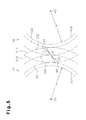
- Fig. 1 shows a screw pump 11 according to the first embodiment.
- the screw pump 11 operates to transport gas, which is fluid.
- the housing of the screw pump 11 includes a rotor housing member 12, a front housing member 13, and a rear housing member 14.
- the front housing member 13 shaped like a lid is joined with the front end (left end as viewed in the drawing) of the rotor housing member 12 with a cylindrical shape.
- the rear housing member 14 shaped like a plate is joined with the rear end (right end as viewed in the drawing) of the rotor housing member 12.
- the rear housing member 14 has a stepped securing hole 14a.
- a shaft receiving body 15 is passed through the securing hole 14a and fastened to the rear housing member 14 using a bolt.
- the shaft receiving body 15 has a first cylindrical portion 160 and a second cylindrical portion 161, which extend parallel with each other in a forward direction.
- the first and second cylindrical portions 160, 161 are each arranged in the rotor housing member 12.
- the first cylindrical portion 160 has a first support hole 190 and the second cylindrical portion 161 has a second support hole 191.
- the first support hole 190 and the second support hole 191 each extend through the shaft receiving body 15.
- a drive shaft 20 is received in the first support hole 190 and a driven shaft 21 is arranged in the second support hole 191.
- a pair of first roller bearings 240 support the drive shaft 20 in a manner rotatable with respect to the shaft receiving body 15.
- a pair of second roller bearings 241 support the driven shaft 21 in a manner rotatable with respect to the shaft receiving body 15.
- the axis of the first cylindrical portion 160 coincides with a first axis 171, which is the rotary axis of the drive shaft 20.
- the axis of the second cylindrical portion 161 coincides with a second axis 181, which is the rotary axis of the driven shaft 21.
- the front end of the drive shaft 20 and the front end of the driven shaft 21 project from the first support hole 190 and the second support hole 191, respectively.
- the rotor housing member 12 accommodates a first screw rotor 17 and a second screw rotor 18.
- the front end (left end as viewed in Fig. 1 ) of the first screw rotor 17 is fixed to the front end of the drive shaft 20 through a joint plate 23 using a bolt.
- the front end of the second screw rotor 18 is fixed to the front end of the driven shaft 21 through another joint plate 23 using a bolt.
- the first screw rotor 17 rotates integrally with the drive shaft 20 and the second screw rotor 18 rotates integrally with the driven shaft 21.
- the first screw rotor 17 is rotated in a first rotational direction X and the second screw rotor 18 is rotated in a second rotational direction Z.
- the first rotational direction X and the second rotational direction Z are opposite to each other.
- the first rotational direction X is a counterclockwise direction
- the second rotational direction Z is a clockwise direction.
- the first screw rotor 17 and the second screw rotor 18 are screw gears each serving as a fluid transport body. Specifically, a drive tooth 17A is formed in the first screw rotor 17 and a driven tooth 18A is provided in the second screw rotor 18.
- the first screw rotor 17 includes a drive screw groove 17a, which extends between adjacent portions of the drive tooth 17A.
- the second screw rotor 18 includes a driven screw groove 18a, which extends between adjacent portions of the driven tooth 18A.
- the axial direction of the first screw rotor 17 is to the direction of the first axis 171, which is the rotary axis of the first screw rotor 17.
- the axial direction of the second screw rotor 18 is to the direction of the second axis 181, which is the rotary axis of the second screw rotor 18.
- the first screw rotor 17 and the second screw rotor 18 are received in the rotor housing member 12 in such a manner that the drive tooth 17A and the driven tooth 18A are arranged in the driven screw groove 18a and the drive screw groove 17a, respectively.
- the first screw rotor 17 and the second screw rotor 18 are configured in such a manner as to provide a sealed space between the screw rotors 17, 18.
- Pump chambers 10 each shaped like a figure eight are defined between each of the first and second screw rotors 17, 18 and an inner circumferential surface 121 of the rotor housing member 12.
- the thickness of the drive tooth 17A decreases gradually from the front end (left end as viewed in Fig. 1 ) of the first screw rotor 17 toward the rear end (right end as viewed in the drawing) and becomes uniform in the vicinity of the rear end.
- the thickness of the driven tooth 18A decreases gradually from the front end (left end as viewed in Fig. 1 ) of the second screw rotor 18 toward the rear end (right end as viewed in the drawing) and becomes uniform in the vicinity of the rear end.
- the interval of the drive tooth 17A, or the width of the drive screw groove 17a decreases gradually from the front end of the first screw rotor 17 toward the rear end and becomes uniform in the vicinity of the rear end.
- the interval of the driven tooth 18A, or the width of the driven screw groove 18a decreases gradually from the front end of the second screw rotor 18 toward the rear end and becomes uniform in the vicinity of the rear end.
- a gear housing member 22 having a lidded cylindrical shape is joined with and fixed to the rear end of the rear housing member 14.
- a rear end 20a of the drive shaft 20 and a rear end 21a of the driven shaft 21 project into the interior of the gear housing member 22.
- a pair of timing gears 25 are secured to the rear ends 20a, 21a in a state engaged with each other.
- An electric motor 26, which is a drive source, is secured to the gear housing member 22.
- An output shaft 26a of the electric motor 26 is connected to the rear end 20a of the drive shaft 20 through a shaft coupling 27.
- An inlet port 28 is defined in the center of the front housing member 13.
- An outlet port 29 is provided in the rear end of the rotor housing member 12. The inlet port 28 and the outlet port 29 each communicate with the pump chambers 10.
- the drive shaft 20 is rotated through the output shaft 26a and the shaft coupling 27. This causes the driven shaft 21 to rotate in the direction different from the rotational direction of the drive shaft 20 through engagement and connection between the two timing gears 25.
- the first screw rotor 17 and the second screw rotor 18 also rotate, drawing gas into the pump chambers 10 through the inlet port 28. The gas is then sent to the outlet port 29 and discharged to the exterior of the pump chambers 10 through the outlet port 29.
- Fig. 3 shows a cross section of the tooth profile of the first screw rotor 17 perpendicular to the rotor axis and that of the second screw rotor 18.
- the cross section of the tooth profile of the first screw rotor 17 perpendicular to the rotor axis corresponds to a cross-sectional shape of the tooth profile of the first screw rotor 17 on an imaginary plane perpendicular to the axial direction of the first screw rotor 17.
- the cross section of tooth profile of the second screw rotor 18 perpendicular to the rotor axis is shaped and sized equally with that of the first screw rotor 17.
- the sign L which is the distance between the first axis 171 and the second axis 181, refers to an inter-pitch distance L between the drive shaft 20 and the driven shaft 21.
- the distance between a first midpoint P1 on the first axis 171 and a second midpoint P2 on the second axis 181 coincides with the inter-pitch distance L.
- the cross section of the tooth profile of the first screw rotor 17 perpendicular to the rotor axis includes a drive tooth top arc A1B1, a drive tooth bottom arc C1D1, a first drive curve A1C1, and a second drive curve B1D1.
- the drive tooth top arc A1B1 is a first circular arc portion extending from a first end A1 to a second end B1 about the first midpoint P1.
- the drive tooth bottom arc C1D1 is a second circular arc portion extending from a first end C1 to a second end D1 about the first midpoint P1.
- the first drive curve A1C1 is a first curved portion that connects the first end A1 of the drive tooth top arc A1B1 to the first end C1 of the drive tooth bottom arc C1D1.
- the second drive curve B1D1 is a second curved portion that connects the second end B1 of the drive tooth top arc A1B1 to the second end D1 of the drive tooth bottom arc C1D1.
- the first midpoint P1 is arranged between the drive tooth top arc A1B1 and the drive tooth bottom arc C1D1.
- the first end A1 and the first end C1 are located on the same side (left side as viewed in Fig. 2(a) ) while the second end B1 and the second end D1 are arranged on the opposite side (right side as viewed in the drawing), with respect to the first midpoint P1.
- the radius of curvature (R2) of the drive tooth bottom arc C1D1 is smaller than the radius of curvature (R1) of the drive tooth top arc A1B1.
- the cross section of the tooth profile of the second screw rotor 18 perpendicular to the rotor axis includes a driven tooth top arc A2B2, a driven tooth bottom arc C2D2, a first driven curve A2C2, and a second driven curve B2D2.
- the driven tooth top arc A2B2 is a first circular arc portion extending from a first end A2 to a second end B2 about the second midpoint P2.
- the driven tooth bottom arc C2D2 is a second circular arc portion extending from a first end C2 to a second end D2 about the second midpoint P2.
- the first driven curve A2C2 is a first curved portion that connects the first end A2 of the driven tooth top arc A2B2 to the first end C2 of the driven tooth bottom arc C2D2.
- the second driven curve B2D2 is a second curved portion that connects the second end B2 of the driven tooth top arc A2B2 to the second end D2 of the driven tooth bottom arc C2D2.
- the second midpoint P2 is arranged between the driven tooth top arc A2B2 and the driven tooth bottom arc C2D2.
- the first end A2 and the first end C2 are located on the same side (right side as viewed in Fig. 2(a) ) while the second end B2 and the second end D2 are arranged on the opposite side (left side as viewed in the drawing) with respect to the second midpoint P2.
- the radius of curvature (R2) of the driven tooth bottom arc C2D2 is smaller than the radius of curvature (R1) of the driven tooth top arc A2B2.
- Fig. 3 illustrates an imaginary straight line M that includes the first midpoint P1 and the second midpoint P2.
- the first end A1 of the drive tooth top arc A1B1 and the first end A2 of the driven tooth top arc A2B2 are located on the imaginary straight line M.
- the first drive curve A1C1 is a trochoidal curve (a first drive trochoidal curve) created by the path of the first end A2 of the driven tooth top arc A2B2.
- the first driven curve A2C2 is a trochoidal curve (a first driven trochoidal curve) created by the path of the first end A1 of the drive tooth top arc A1B1.
- the second drive curve B1D1 is a composite curve formed by a drive involute curve B1E1 and a second drive trochoidal curve E1D1 that extend continuously from each other at a first intersection point E1.
- the drive involute curve B1E1 extends continuously from the second end B1 of the drive tooth top arc A1B1.
- the second drive trochoidal curve E1D1 extends continuously from the second end D1 of the drive tooth bottom arc C1D1.
- the second driven curve B2D2 is a composite curve formed by a driven involute curve B2E2 and a second driven trochoidal curve E2D2 that extend continuously from each other at a second intersection point E2.
- the driven involute curve B2E2 extends continuously from the second end B2 of the driven tooth top arc A2B2.
- the second driven trochoidal curve E2D2 extends continuously from the second end D2 of the driven tooth bottom arc C2D2.
- the drive involute curve B1E1 is defined by a first base circle Co1, which is illustrated in Fig. 4 .
- the center of the first base circle Co1 is the first midpoint P1.
- An involute radius Ro which is the radius of the first base circle Co1
- is smaller than a pitch radius r L/2, which is a half of the inter-pitch distance L (Ro ⁇ r).
- the driven involute curve B2E2 is defined by a second base circle Co2, which is illustrated in Fig. 4 .
- the center of the second base circle Co2 is the second midpoint P2.
- the second base circle Co2 has the involute radius Ro with respect to the second midpoint P2.
- the second drive trochoidal curve E1D1 is created by the path of the second end B2 of the driven tooth top arc A2B2.
- the second driven trochoidal curve E2D2 is created by the path of the second end B1 of the drive tooth top arc A1B1.
- the angle of the drive tooth top arc A1B1 about the first midpoint P1 and the angle of the driven tooth top arc A2B2 about the second midpoint P2 are each referred to as a first angle ⁇ 1.
- the angle of the drive tooth bottom arc C1D1 about the first midpoint P1 and the angle of the driven tooth bottom arc C2D2 about the second midpoint P2 are each referred to as a second angle ⁇ 2.
- the first angle ⁇ 1 of the drive tooth top arc A1B1 is equal to the first angle ⁇ 1 of the driven tooth top arc A2B2.
- the second angle ⁇ 2 of the drive tooth bottom arc C1D1 is equal to the second angle ⁇ 2 of the driven tooth bottom arc C2D2.
- the first angle ⁇ 1 and the second angle ⁇ 2 are both less than 180 degrees ( ⁇ 1 ⁇ 180°, ⁇ 2 ⁇ 180°).
- the first screw rotor 17 has a drive tooth top surface 172, which is the tooth top surface of the drive tooth 17A, and a drive tooth bottom surface 173, which is the tooth bottom surface of the drive screw groove 17a.
- a cross section of the drive tooth top surface 172 perpendicular to the rotor axis is the drive tooth top arc A1B1.
- a cross section of the drive tooth bottom surface 173 perpendicular to the rotor axis is the drive tooth bottom arc C1D1.
- the drive tooth top surface 172 and the drive tooth bottom surface 173 are circumferential surfaces that extend spirally along the first axis 171.
- the second screw rotor 18 has a driven tooth top surface 182, which is the tooth top surface of the driven tooth 18A, and a driven tooth bottom surface 183, which is the tooth bottom surface of the driven screw groove 18a.
- a cross section of the driven tooth top surface 182 perpendicular to the rotor axis is the driven tooth top arc A2B2.
- a cross section of the driven tooth bottom surface 183 perpendicular to the rotor axis is the driven tooth bottom arc C2D2.
- the driven tooth top surface 182 and the driven tooth bottom surface 183 are circumferential surfaces that extend spirally along the second axis 181.
- the axial dimension of the drive tooth top surface 172 is substantially equal to the axial dimension of the drive tooth bottom surface 173. If the first angle ⁇ 1 of the second screw rotor 18 is equal to the second angle ⁇ 2, the axial dimension of the driven tooth top surface 182 is substantially equal to the axial dimension of the driven tooth bottom surface 183.
- the axial dimension of the drive tooth top surface 172 is a dimension measured along the first axis 171 and the axial dimension of the driven tooth top surface 182 is a dimension measured along the second axis 181.
- the first screw rotor 17 has a drive tooth side surface 174, which is the side surface of the drive tooth 17A
- the second screw rotor 18 has a driven tooth side surface 184, which is the side surface of the driven tooth 18A.
- the drive tooth side surface 174 is opposed to the driven tooth side surface 184.
- a cross section of the drive tooth side surface 174 perpendicular to the rotor axis is the second drive curve B1D1.
- a cross section of the driven tooth side surface 184 perpendicular to the rotor axis is the second driven curve B2D2.
- the drive tooth side surface 174 is a curved surface that connects the drive tooth top surface 172 to the drive tooth bottom surface 173.
- the driven tooth side surface 184 is a curved surface that connects the driven tooth top surface 182 to the driven tooth bottom surface 183.
- the first screw rotor 17 and the second screw rotor 18 rotate in a non-contact manner with each other. However, as the clearance between the first screw rotor 17 and the second screw rotor 18 becomes substantially eliminated, a linear seal portion is formed apparently.
- the angle between the drive tooth top surface 172 and the drive tooth side surface 174 is a drive tooth top angle ⁇ .
- the angle between the driven tooth top surface 182 and the driven tooth side surface 184 is a driven tooth top angle ⁇ .
- the angle between the inner circumferential surface 121 of the rotor housing member 12 and the drive tooth side surface 174 is a first clearance angle ⁇ .
- the angle between the inner circumferential surface 121 of the rotor housing member 12 and the driven tooth side surface 184 is a second clearance angle ⁇ .
- the drive tooth top angle ⁇ is an obtuse angle (an angle greater than 90° and smaller than 180°) and the first clearance angle ⁇ is an acute angle (an angle less than 90°).
- the driven tooth top angle ⁇ is an obtuse angle and the second clearance angle 5 is an acute angle.
- the first midpoint P1, the second midpoint P2, and the inter-pitch distance L are determined.
- the circle about the first midpoint P1 with the pitch radius r is referred to as a first pitch circle C31.
- the circle about the second midpoint P2 with the pitch radius r is referred to as a second pitch circle C32.
- the pitch radius r is equal to L/2. That is, the first pitch circle C31 and the second pitch circle C32 contact each other at a contact point F, which is located at the midpoint between the first midpoint P1 and the second midpoint P2.
- the first outer circle C11 having an outer radius R1 greater than the pitch radius r and the first inner circle C21 with an inner radius R2 smaller than the pitch radius r are determined with respect to the first midpoint P1 (R2 ⁇ r ⁇ R1).
- the second outer circle C12 with the outer radius R1 and the second inner circle C22 with the inner radius R2 are determined with respect to the second midpoint P2.
- the first base circle Co1 and the second base circle Co2 are determined.
- the involute radius Ro is set to a value less than the pitch radius r (Ro ⁇ r).
- a created drive involute curve I1 is determined in such a manner that the created drive involute curve I1 includes the contact point F.
- the intersection point between the created drive involute curve I1 and the first outer circle C11 is the second end B1 of the drive tooth top arc A1B1.
- a created driven involute curve I2 is determined in such a manner that the created driven involute curve I2 includes the contact point F.
- the intersection point between the created driven involute curve I2 and the second outer circle C12 is the second end B2 of the driven tooth top arc A2B2.
- a second created drive trochoidal curve J1 is determined by the path of the second end B2 when the first screw rotor 17 and the second screw rotor 18 are rotated.
- a second created drive trochoidal curve J1 is created by revolution of the second screw rotor 18 around the first screw rotor 17 with the second pitch circle C32 held in contact with the first pitch circle C31.
- the intersection point between the second created drive trochoidal curve J1 and the first inner circle C21 is the second end D1 of the drive tooth bottom arc C1D1.
- the intersection point between the second created drive trochoidal curve J1 and the created drive involute curve I1 is the first intersection point E1.
- the second created drive trochoidal curve J1 is connected to the created drive involute curve I1 at the first intersection point E1.
- the portion of the created drive involute curve I1 between the second end B1 and the first intersection point E1 forms the drive involute curve B1E1.
- the portion of the second created drive trochoidal curve J1 between the first intersection point E1 and the second end D1 forms the second drive trochoidal curve E1D1.
- the tangential line of the drive involute curve B1E1 coincides with the tangential line of the second drive trochoidal curve E1D1 at the first intersection point E1.
- the first intersection point E1 is a connection point between the drive involute curve B1E1 and the second drive trochoidal curve E1D1.
- a second created driven trochoidal curve J2 is determined by the path of the second end B1 when the first screw rotor 17 and the second screw rotor 18 are rotated.
- a second created driven trochoidal curve J2 is created by revolution of the first screw rotor 17 around the second screw rotor 18 with the first pitch circle C31 held in contact with the second pitch circle C32.
- the intersection point between the second created driven trochoidal curve J2 and the second inner circle C22 is the second end D2 of the driven tooth bottom arc C2D2.
- the intersection point between the second created driven trochoidal curve J2 and the created driven involute curve I2 is the second intersection point E2.
- the second created driven trochoidal curve J2 is connected to the created driven involute curve I2 at the second intersection point E2.
- the portion of the created driven involute curve I2 between the second end B2 and the second intersection point E2 forms the driven involute curve B2E2.
- the portion of the second created driven trochoidal curve J2 between the second intersection point E2 and the second end D2 forms the second driven trochoidal curve E2D2.
- the tangential line of the driven involute curve B2E2 coincides with the tangential line of the second driven trochoidal curve E2D2 at the second intersection point E2.
- the second intersection point E2 is a connection point between the driven involute curve B2E2 and the second driven trochoidal curve E2D2.
- the imaginary straight line M including the first midpoint P1 and the second midpoint P2 is then determined as illustrated in Fig. 7 .
- the intersection point between the imaginary straight line M and the first outer circle C11 outside the range between the first midpoint P1 and the second midpoint P2 is the first end A1 of the drive tooth top arc A1B1.
- the intersection point between the imaginary straight line M and the second outer circle C12 outside the range between the first midpoint P1 and the second midpoint P2 is the first end A2 of the driven tooth top arc A2B2.
- a first created drive trochoidal curve K1 is determined by the path of the first end A2 of the second screw rotor 18 when the first screw rotor 17 and the second screw rotor 18 are rotated.
- the first created drive trochoidal curve K1 is created by revolution of the second screw rotor 18 around the first screw rotor 17 with the second pitch circle C32 held in contact with the first pitch circle C31.
- the first created drive trochoidal curve K1 includes the first end A1 of the first screw rotor 17.
- the intersection point between the first created drive trochoidal curve K1 and the first inner circle C21 is the first end C1 of the drive tooth bottom arc C1D1.
- the portion of the first created drive trochoidal curve K1 between the first end A1 and the first end C1 forms the first drive curve A1C1.
- a first created driven trochoidal curve K2 is determined by the path of the first end A1 of the first screw rotor 17 when the first screw rotor 17 and the second screw rotor 18 are rotated.
- the first created driven trochoidal curve K2 is created by revolution of the first screw rotor 17 around the second screw rotor 18 with the first pitch circle C31 held in contact with the second pitch circle C32.
- the first created driven trochoidal curve K2 includes the first end A2 of the second screw rotor 18.
- the intersection point between the first created driven trochoidal curve K2 and the second inner circle C22 is the first end C2 of the driven tooth bottom arc C2D2.
- the portion of the first created driven trochoidal curve K2 between the first end A2 and the first end C2 forms the first driven curve A2C2.
- the portion of the first outer circle C11 between the first end A1 and the second end B1 forms the drive tooth top arc A1B1.
- the drive tooth top arc A1B1 is determined in such a manner that an acute angle is formed between the drive tooth top arc A1B1 and the first drive curve A1C1.
- the portion of the first inner circle C21 between the first end C1 and the second end D1 forms the drive tooth bottom arc C1D1.
- the drive tooth bottom arc C1D1 is determined in such a manner that the first midpoint P1 is provided between the drive tooth top arc A1B1 and the drive tooth bottom arc C1D1.
- the radius of curvature of the drive tooth top arc A1B1 is the outer radius R1 and the radius of curvature of the drive tooth bottom arc C1D1 is the inner radius R2.
- the portion of the second outer circle C12 between the first end A2 and the second end B2 forms the driven tooth top arc A2B2.
- the driven tooth top arc A2B2 is determined in such a manner that an acute angle is formed between the driven tooth top arc A2B2 and the first driven curve A2C2.
- the portion of the second inner circle C22 between the first end C2 and the second end D2 forms the driven tooth bottom arc C2D2.
- the driven tooth bottom arc C2D2 is determined in such a manner that the second midpoint P2 is provided between the driven tooth top arc A2B2 and the driven tooth bottom arc C2D2.
- the first end A2 of the second screw rotor 18 moves along the first drive curve A1C1, as illustrated in Fig. 8(a) .
- the first end A1 of the first screw rotor 17 then moves along the first driven curve A2C2.
- Fig. 9(a), Fig. 9(b), and Fig. 9(c) show a first example, a second example, and a third example, respectively, of the tooth profiles of the first screw rotor 17 and the second screw rotor 18 according to the present invention.
- Fig. 9(d), Fig. 9(e), and Fig. 9(f) show a first comparative example, a second comparative example, and a third comparative example, respectively, of the tooth profiles of the first and second conventional screw rotors 90A, 90B, which are shown in Fig. 11 .
- the pitch radius r, the outer radius R1, and the inner radius R2 are set to 40 mm, 55.5 mm, and 24.5 mm, respectively.
- the involute radius Ro is smaller than the inner radius R2 (Ro ⁇ R2), and Ro is set to 16.75 mm.
- the involute radius Ro is greater than the inner radius R2 and smaller than the pitch radius r (R2 ⁇ Ro ⁇ r), and Ro is set to 32.25 mm.
- the involute radius Ro when the involute radius Ro is smaller than the pitch radius r (Ro ⁇ r), the values ⁇ 1 and ⁇ 2 of the first and second screw rotors 17, 18 are greater than the values ⁇ 1 and ⁇ 2 of the first and second conventional screw rotors 90A, 90B.
- the involute radius Ro is greater than or equal to the pitch radius r (r ⁇ Ro)
- the drive involute curve B1E1 is not engaged with the driven involute curve B2E2.
- the first embodiment has the following advantages.
- the involute curve W1Y1 illustrated in Fig. 11 is indirectly connected to the tooth top arc Q1R1 through the outer circular arc R1W1.
- This arrangement causes the foreign objects to be easily collected in an area from the clearance near the tooth bottom surface to the seal portion between the tooth top surface and the tooth bottom surface. The foreign obstacles are thus easily caught.
- this problem is solved.
- the first embodiment may be modified as follows.
- the thickness (the axial dimension) of the drive tooth 17A may be uniform from the front end to the rear end of the first screw rotor 17, instead of decreasing from the front end to the rear end of the first screw rotor 17.
- the thickness of the driven tooth 18A may be uniform from the front end to the rear end of the second screw rotor 18.
- the number of the drive teeth 17A of the first screw rotor 17 and the number of the driven teeth 18A of the second screw rotor 18 are not restricted to one but may be two.
- the first angle ⁇ 1 and the second angle ⁇ 2 may be altered as needed.
- the first angle ⁇ 1 of the first screw rotor 17 may be greater than the second angle ⁇ 2. That is, the first angle ⁇ 1 may be set to a value greater than 180° while the second angle ⁇ 2 is set to a value smaller than 180°.
- the circumferential dimension of the drive tooth top arc A1B1 is greater than the circumferential dimension of the driven tooth bottom arc C2D2.
- the first angle ⁇ 1 of the second screw rotor 18 is set to a value smaller than the second angle ⁇ 2.
- the circumferential dimension of the driven tooth top arc A2B2 is set to a value smaller than the circumferential dimension of the driven tooth bottom arc C2D2.
- the axial dimension of the drive tooth 17A is greater than the axial dimension of the driven tooth 18A.
- the width (the axial dimension) of the drive screw groove 17a is smaller than the width of the driven screw groove 18a.
Landscapes
- Engineering & Computer Science (AREA)
- Mechanical Engineering (AREA)
- General Engineering & Computer Science (AREA)
- Rotary Pumps (AREA)
- Applications Or Details Of Rotary Compressors (AREA)
Applications Claiming Priority (2)
| Application Number | Priority Date | Filing Date | Title |
|---|---|---|---|
| JP2006240042 | 2006-09-05 | ||
| PCT/JP2007/067125 WO2008029759A1 (fr) | 2006-09-05 | 2007-09-03 | Pompe à vis et rotor en forme de vis |
Publications (2)
| Publication Number | Publication Date |
|---|---|
| EP2060789A1 true EP2060789A1 (de) | 2009-05-20 |
| EP2060789A4 EP2060789A4 (de) | 2013-08-28 |
Family
ID=39157186
Family Applications (1)
| Application Number | Title | Priority Date | Filing Date |
|---|---|---|---|
| EP07806598.4A Withdrawn EP2060789A4 (de) | 2006-09-05 | 2007-09-03 | Schneckenpumpe und schneckenrotor |
Country Status (6)
| Country | Link |
|---|---|
| US (1) | US7798794B2 (de) |
| EP (1) | EP2060789A4 (de) |
| JP (1) | JP4893630B2 (de) |
| KR (1) | KR100976112B1 (de) |
| TW (1) | TWI336373B (de) |
| WO (1) | WO2008029759A1 (de) |
Cited By (6)
| Publication number | Priority date | Publication date | Assignee | Title |
|---|---|---|---|---|
| EP2148046A2 (de) | 2008-07-23 | 2010-01-27 | United Technologies Corporation | Turbinenrahmen mit betätigbarer variabler Geometrie |
| CN103195716A (zh) * | 2013-05-07 | 2013-07-10 | 巫修海 | 一种新型齿形螺杆型线 |
| EP2295801A3 (de) * | 2009-07-22 | 2015-06-24 | Kabushiki Kaisha Toyota Jidoshokki | Schraubenpumpenrotor |
| CN104776027A (zh) * | 2013-04-26 | 2015-07-15 | 巫修海 | 严格密封型干式螺杆真空泵螺杆转子型线 |
| CN105697363A (zh) * | 2016-03-11 | 2016-06-22 | 天津华科螺杆泵技术有限公司 | 一种带有渐开线传力边的非对称齿形的双头螺旋螺杆 |
| CN107084131A (zh) * | 2017-06-08 | 2017-08-22 | 中国石油大学(华东) | 一种基于偏心圆渐开线的全光滑螺杆转子 |
Families Citing this family (8)
| Publication number | Priority date | Publication date | Assignee | Title |
|---|---|---|---|---|
| IT1396898B1 (it) * | 2008-12-02 | 2012-12-20 | Marzocchi Pompe S P A | Profilo dentato per rotori di pompe volumetriche ad ingranaggi a dentatura esterna. |
| CN105317677B (zh) * | 2015-11-09 | 2017-10-24 | 中国石油大学(华东) | 一种无锐角尖点的螺杆转子 |
| CN105240277B (zh) * | 2015-11-09 | 2017-05-03 | 中国石油大学(华东) | 一种双螺杆真空泵的全光滑的螺杆转子 |
| CN105332914B (zh) * | 2015-11-09 | 2017-05-31 | 中国石油大学(华东) | 一种全光滑的螺杆转子 |
| CN108223360B (zh) * | 2018-02-28 | 2024-05-07 | 上海诺科泵业有限公司 | 非对称螺杆转子、其端面型线的生成方法及双螺杆泵 |
| CN108443145B (zh) * | 2018-05-22 | 2020-04-21 | 天津华科螺杆泵技术有限公司 | 一种双头螺旋螺杆及采用该螺杆的双螺杆泵和干式真空螺杆泵 |
| CN109854504B (zh) * | 2019-04-02 | 2020-03-24 | 萨震压缩机(上海)有限公司 | 节能螺杆型线 |
| CN113638880B (zh) * | 2021-09-06 | 2023-03-21 | 台州学院 | 一种螺杆真空泵及其螺杆转子 |
Citations (1)
| Publication number | Priority date | Publication date | Assignee | Title |
|---|---|---|---|---|
| WO2005113984A1 (ja) * | 2004-05-24 | 2005-12-01 | Nabtesco Corporation | スクリューロータ及びスクリュー式流体機械 |
Family Cites Families (12)
| Publication number | Priority date | Publication date | Assignee | Title |
|---|---|---|---|---|
| GB112104A (en) * | 1917-07-05 | 1917-12-27 | Edward Nuebling | Improvements in or relating to Rotary Meters, Pumps and Motors. |
| US2994562A (en) * | 1959-02-05 | 1961-08-01 | Warren Pumps Inc | Rotary screw pumping of thick fibrous liquid suspensions |
| JPS5746083A (en) | 1980-09-01 | 1982-03-16 | Shigeyoshi Osada | Improved quimby pump |
| US4792294A (en) * | 1986-04-11 | 1988-12-20 | Mowli John C | Two-stage screw auger pumping apparatus |
| AT400693B (de) * | 1994-05-17 | 1996-02-26 | Hladik Herta | Ringbuchmechanik |
| KR0133154B1 (ko) * | 1994-08-22 | 1998-04-20 | 이종대 | 무단 압축형 스크류식 진공펌프 |
| JP2904719B2 (ja) | 1995-04-05 | 1999-06-14 | 株式会社荏原製作所 | スクリューロータ及びその歯形の軸直角断面形状を決定する方法並びにスクリュー機械 |
| JP3831110B2 (ja) * | 1998-03-25 | 2006-10-11 | 大晃機械工業株式会社 | 真空ポンプのスクリューロータ |
| DE59811390D1 (de) * | 1998-10-23 | 2004-06-17 | Busch Sa Atel | Zwillings-Förderschraubenrotoren |
| CN1337528A (zh) * | 2001-09-12 | 2002-02-27 | 浙江大学 | 一种新型齿形的螺杆 |
| JP4068083B2 (ja) * | 2004-06-14 | 2008-03-26 | 神港精機株式会社 | スクリューロータ |
| US7625191B2 (en) * | 2005-02-16 | 2009-12-01 | Ateliers Busch Sa | Rotary displacement machines having rotors of asymmetrical profile |
-
2007
- 2007-09-03 WO PCT/JP2007/067125 patent/WO2008029759A1/ja active Application Filing
- 2007-09-03 US US11/992,700 patent/US7798794B2/en not_active Expired - Fee Related
- 2007-09-03 KR KR1020087007874A patent/KR100976112B1/ko not_active IP Right Cessation
- 2007-09-03 JP JP2007553400A patent/JP4893630B2/ja not_active Expired - Fee Related
- 2007-09-03 EP EP07806598.4A patent/EP2060789A4/de not_active Withdrawn
- 2007-09-05 TW TW096133020A patent/TWI336373B/zh not_active IP Right Cessation
Patent Citations (1)
| Publication number | Priority date | Publication date | Assignee | Title |
|---|---|---|---|---|
| WO2005113984A1 (ja) * | 2004-05-24 | 2005-12-01 | Nabtesco Corporation | スクリューロータ及びスクリュー式流体機械 |
Non-Patent Citations (2)
| Title |
|---|
| DATABASE WPI Week 200237 Thomson Scientific, London, GB; AN 2002-330858 XP002704010, & CN 1 337 528 A (UNIV ZHEJIANG) 27 February 2002 (2002-02-27) * |
| See also references of WO2008029759A1 * |
Cited By (9)
| Publication number | Priority date | Publication date | Assignee | Title |
|---|---|---|---|---|
| EP2148046A2 (de) | 2008-07-23 | 2010-01-27 | United Technologies Corporation | Turbinenrahmen mit betätigbarer variabler Geometrie |
| EP2295801A3 (de) * | 2009-07-22 | 2015-06-24 | Kabushiki Kaisha Toyota Jidoshokki | Schraubenpumpenrotor |
| CN104776027A (zh) * | 2013-04-26 | 2015-07-15 | 巫修海 | 严格密封型干式螺杆真空泵螺杆转子型线 |
| CN104776027B (zh) * | 2013-04-26 | 2016-10-26 | 巫修海 | 严格密封型干式螺杆真空泵螺杆转子 |
| CN103195716A (zh) * | 2013-05-07 | 2013-07-10 | 巫修海 | 一种新型齿形螺杆型线 |
| CN103195716B (zh) * | 2013-05-07 | 2015-09-02 | 巫修海 | 一种新型齿形螺杆型线 |
| CN105697363A (zh) * | 2016-03-11 | 2016-06-22 | 天津华科螺杆泵技术有限公司 | 一种带有渐开线传力边的非对称齿形的双头螺旋螺杆 |
| CN107084131A (zh) * | 2017-06-08 | 2017-08-22 | 中国石油大学(华东) | 一种基于偏心圆渐开线的全光滑螺杆转子 |
| CN107084131B (zh) * | 2017-06-08 | 2019-05-31 | 中国石油大学(华东) | 一种基于偏心圆渐开线的全光滑螺杆转子 |
Also Published As
| Publication number | Publication date |
|---|---|
| TWI336373B (en) | 2011-01-21 |
| JP4893630B2 (ja) | 2012-03-07 |
| US20100178191A1 (en) | 2010-07-15 |
| EP2060789A4 (de) | 2013-08-28 |
| US7798794B2 (en) | 2010-09-21 |
| JPWO2008029759A1 (ja) | 2010-01-21 |
| TW200827557A (en) | 2008-07-01 |
| KR100976112B1 (ko) | 2010-08-16 |
| KR20080046220A (ko) | 2008-05-26 |
| WO2008029759A1 (fr) | 2008-03-13 |
Similar Documents
| Publication | Publication Date | Title |
|---|---|---|
| EP2060789A1 (de) | Schneckenpumpe und schneckenrotor | |
| US8096795B2 (en) | Oil pump rotor | |
| EP2295801B1 (de) | Schraubenpumperotor | |
| US8360762B2 (en) | Oil pump rotor | |
| CN1143051C (zh) | 带有经改进的螺旋转子结构的流体排放装置 | |
| JP2002536593A (ja) | 容積形機械、特にポンプに搭載される複式送出しスクリュー | |
| KR20060047511A (ko) | 스크루식 유체 기계 | |
| US9140258B2 (en) | Gear machine having a non-circular low-pressure connection | |
| US20080193315A1 (en) | Roots-type fluid machine | |
| EP3828415B1 (de) | Interne getriebepumpe | |
| US9175682B2 (en) | Planetary rotor machine manifold | |
| US7819645B2 (en) | Internal gear pump | |
| EP1666727B1 (de) | Ölpumpenrotor | |
| CN113236561B (zh) | 一种变螺距的同向啮合双螺杆压缩机转子及压缩机 | |
| US7118359B2 (en) | Oil pump rotor | |
| EP3521621B1 (de) | Innenumlaufende zahnradpumpe | |
| GB2092676A (en) | Rotary Positive-displacement Fluid-machines | |
| WO2018198801A1 (ja) | 歯車ポンプ用ロータおよび歯車ポンプ | |
| JP2004278350A (ja) | ロータ及びそれを備えたルーツ式流体機械 | |
| JP4271654B2 (ja) | スクリュロータ | |
| WO2018198798A1 (ja) | 歯車ポンプ用ロータおよび歯車ポンプ | |
| EP1546561A1 (de) | Verdichter | |
| JP2006063883A (ja) | 内接歯車式ポンプ | |
| JP2002266652A (ja) | 二軸機械式過給機用ケーシング |
Legal Events
| Date | Code | Title | Description |
|---|---|---|---|
| PUAI | Public reference made under article 153(3) epc to a published international application that has entered the european phase |
Free format text: ORIGINAL CODE: 0009012 |
|
| 17P | Request for examination filed |
Effective date: 20080326 |
|
| AK | Designated contracting states |
Kind code of ref document: A1 Designated state(s): AT BE BG CH CY CZ DE DK EE ES FI FR GB GR HU IE IS IT LI LT LU LV MC MT NL PL PT RO SE SI SK TR |
|
| AX | Request for extension of the european patent |
Extension state: AL BA HR MK RS |
|
| DAX | Request for extension of the european patent (deleted) | ||
| A4 | Supplementary search report drawn up and despatched |
Effective date: 20130729 |
|
| RIC1 | Information provided on ipc code assigned before grant |
Ipc: F04C 2/107 20060101ALI20130722BHEP Ipc: F04C 2/16 20060101AFI20130722BHEP Ipc: F04C 18/16 20060101ALI20130722BHEP |
|
| STAA | Information on the status of an ep patent application or granted ep patent |
Free format text: STATUS: THE APPLICATION IS DEEMED TO BE WITHDRAWN |
|
| 18D | Application deemed to be withdrawn |
Effective date: 20140227 |