EP2059746B1 - Kabeldurchführung - Google Patents
Kabeldurchführung Download PDFInfo
- Publication number
- EP2059746B1 EP2059746B1 EP07802768A EP07802768A EP2059746B1 EP 2059746 B1 EP2059746 B1 EP 2059746B1 EP 07802768 A EP07802768 A EP 07802768A EP 07802768 A EP07802768 A EP 07802768A EP 2059746 B1 EP2059746 B1 EP 2059746B1
- Authority
- EP
- European Patent Office
- Prior art keywords
- sleeve
- cable bushing
- bushing according
- cable
- cover
- Prior art date
- Legal status (The legal status is an assumption and is not a legal conclusion. Google has not performed a legal analysis and makes no representation as to the accuracy of the status listed.)
- Not-in-force
Links
- 238000007789 sealing Methods 0.000 claims description 10
- 238000005253 cladding Methods 0.000 claims 2
- 238000009413 insulation Methods 0.000 claims 1
- 239000006260 foam Substances 0.000 description 13
- 238000000465 moulding Methods 0.000 description 5
- 238000005057 refrigeration Methods 0.000 description 3
- 210000004907 gland Anatomy 0.000 description 2
- 238000009434 installation Methods 0.000 description 2
- 238000004873 anchoring Methods 0.000 description 1
- 238000010276 construction Methods 0.000 description 1
- 238000006073 displacement reaction Methods 0.000 description 1
- 230000000694 effects Effects 0.000 description 1
- 230000005489 elastic deformation Effects 0.000 description 1
- 229920002457 flexible plastic Polymers 0.000 description 1
- 239000006261 foam material Substances 0.000 description 1
- 238000007373 indentation Methods 0.000 description 1
- 238000001746 injection moulding Methods 0.000 description 1
- 238000003780 insertion Methods 0.000 description 1
- 230000037431 insertion Effects 0.000 description 1
- 239000012774 insulation material Substances 0.000 description 1
- 239000007788 liquid Substances 0.000 description 1
- 239000000463 material Substances 0.000 description 1
Images

Classifications
-
- H—ELECTRICITY
- H05—ELECTRIC TECHNIQUES NOT OTHERWISE PROVIDED FOR
- H05K—PRINTED CIRCUITS; CASINGS OR CONSTRUCTIONAL DETAILS OF ELECTRIC APPARATUS; MANUFACTURE OF ASSEMBLAGES OF ELECTRICAL COMPONENTS
- H05K5/00—Casings, cabinets or drawers for electric apparatus
- H05K5/02—Details
- H05K5/0247—Electrical details of casings, e.g. terminals, passages for cables or wiring
-
- F—MECHANICAL ENGINEERING; LIGHTING; HEATING; WEAPONS; BLASTING
- F25—REFRIGERATION OR COOLING; COMBINED HEATING AND REFRIGERATION SYSTEMS; HEAT PUMP SYSTEMS; MANUFACTURE OR STORAGE OF ICE; LIQUEFACTION SOLIDIFICATION OF GASES
- F25D—REFRIGERATORS; COLD ROOMS; ICE-BOXES; COOLING OR FREEZING APPARATUS NOT OTHERWISE PROVIDED FOR
- F25D23/00—General constructional features
- F25D23/06—Walls
- F25D23/065—Details
-
- F—MECHANICAL ENGINEERING; LIGHTING; HEATING; WEAPONS; BLASTING
- F25—REFRIGERATION OR COOLING; COMBINED HEATING AND REFRIGERATION SYSTEMS; HEAT PUMP SYSTEMS; MANUFACTURE OR STORAGE OF ICE; LIQUEFACTION SOLIDIFICATION OF GASES
- F25D—REFRIGERATORS; COLD ROOMS; ICE-BOXES; COOLING OR FREEZING APPARATUS NOT OTHERWISE PROVIDED FOR
- F25D2400/00—General features of, or devices for refrigerators, cold rooms, ice-boxes, or for cooling or freezing apparatus not covered by any other subclass
- F25D2400/40—Refrigerating devices characterised by electrical wiring
Definitions
- the present invention relates to a grommet for tightly guiding a cable, a pipe or the like through a wall.
- a field of application of such bushings is, for example, the construction of refrigeration appliances.
- the housing of a domestic refrigerator generally has a fixed outer wall and a storage compartment bounding inner wall, and a space between the outer and inner walls is filled by expansion of a foam material. Cables crossing the inner and outer walls and the foam layer must be reliably sealed on the inner and outer walls to prevent the foam from escaping.
- a possible approach for this is a labyrinth seal in which the conduit to be performed is passed through a tortuous channel, the length and cross-section of which are such that foam entering the channel bonds and solidifies therein before reaching the opposite channel end.
- An inherent disadvantage of this approach is the footprint of the channel and the difficulty of routing the cable itself through the channel.
- a simpler approach is to install in a wall opening a flexible sealing lip having an opening through which the cable is guided, wherein it elastically expands the opening.
- a flexible sealing lip has only a limited compressive strength, and since it is not able to fix the cable, leaks due to a displacement of the cable are not completely excluded.
- a cable gland according to the preamble of claim 1 is made WO 2004075366 known.
- the object of the invention is to provide a grommet, which makes it possible to pass cables together with a thickened header through a wall opening and yet to ensure a secure seal the wall opening.
- the object is achieved by a cable feedthrough with an opening formed in a wall, surrounded by a first sleeve opening, wherein the sleeve is provided on at least a portion of its length with an open-edge first slot, and with a lid, which engages an engaging in the first sleeve second sleeve, which is provided on at least part of its length with an open-edge second slot, wherein an overlap region of the two slots is filled by a cable extending through the opening.
- This grommet allows the installation of a cable together with a head piece attached thereto by the first sleeve is dimensioned far enough to pass head and cable, while the width of the first slot is sufficient only to receive the cable therein - preferably under clamping.
- the lid When a medium such as foam to be sealed is located on the side of the wall from which the second slot is inserted into the first one, the lid is secured in position by the pressure of that medium. If the medium is located on the opposite side of the wall, the second sleeve is preferably locked in the first sleeve for securing.
- the second sleeve may carry on its edge facing away from the lid a latching projection which engages behind a side facing away from the lid edge of the first sleeve.
- the second sleeve may have a plurality of slots distributed over its circumference. Of these slots, generally one is the above-mentioned second slot through which the cable passes.
- the second sleeve fills the free cross-section of the first sleeve so that a medium to be sealed against can not penetrate between the sleeves.
- the above-mentioned wall is part of a molded part, which in turn can be mounted in a wall opening of an inner lining or an outer lining of a refrigeration device.
- a molded part can be conveniently manufactured for example by injection molding. Thanks to its realization, the cable feedthrough according to the invention can be applied to wall openings of any walls in a molded part, the only requirement that these walls have to fulfill being that the molded part must be attachable to them.
- the molding is preferably provided with a circumferential sealing lip, which prevents in the case of installation of the cable gland on the inner and / or outer lining of a refrigerator, that processed in liquid starting components heat insulation material the assembly point exits.
- a circumferential cable holder makes it possible to accommodate any excess lengths of the cable clearly.
- the molded part is designed as a hollow body which is open on one side, and the cover is dimensioned in order to close the open side of the hollow body.
- the head of the cable can be accommodated in the cavity of the molded part and then the cavity can be closed with the lid.
- the cover For fixing and / or fixing the position of the cover on the hollow body, the cover preferably carries a engaging in contact with side walls of the hollow body in its interior circumferential web.
- the cover is articulated by a hinge in a fixedly connected to the second sleeve base part and a pivotable against the base flap.
- the flap can be swung open, access to the interior of the molding, for example, to repair the head accommodated therein, is possible.
- the above-mentioned web is advantageously interrupted at the level of the joint.
- the grommet can serve to accommodate a temperature sensor in the hollow body, which can serve for example in a refrigerator for the temperature control of the interior.
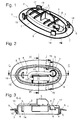
- Fig. 1 is a perspective view of a molded part of the cable duct according to the invention, which is intended to be mounted in an inner container wall of a foam-insulated refrigerator.
- the figure shows a view of the insulating foam layer facing side of the molded body 1.
- the molded body comprises an elliptical base plate 2 in outline, from which protrude a plurality of, the base plate 2 stiffening and the molded body 1 in the foam layer anchoring ribs 3.
- the base plate 2 is surrounded by a circumferential, rigid side wall 4.
- the side wall 4 is at its in Fig. 1 invisible, facing away from the base plate 2 edge with a concentrically surrounding skirt 5, which in turn is surrounded by a flat conical flexible sealing lip 6.
- Fig. 2 shows in a plan view of an insight into an area bounded by the base plate 2 and the side wall 4 interior.
- a circular opening 7 is formed adjacent to a longitudinal end of the base plate 2 and offset from a longitudinal center plane GG.
- the opening 7 is bordered by a projecting into the interior of the sleeve 8.
- a slot 9 is formed, which is open to a side facing away from the base plate 2 edge of the sleeve 8.
- Fig. 2 shows a cable 10 which extends through the opening 7, is inserted into the slot 9 and is connected to a temperature sensor 11, which is fixed in position by protruding from the base plate 2 in the interior webs 12.
- a projecting into the interior of the column 13 is formed, which carries a latching projection 14.
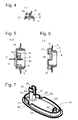
- the locking lugs 15 are first pressed under elastic deformation of the skirt 5 against the side wall 4 and move back after passing the opening, so that the inner container wall between the Locking lugs 15 on the one hand and the elastically deformed sealing lip 6 on the other hand is clamped.
- the voltage applied to the inner container wall outer edge of the sealing lip 6 ensures foam tightness of the connection between the inner container wall and the molded body.
- FIGS. 1 . 5 and 6 a recess 16 of the base plate 2 can be seen, which extends from a slot 9 opposite edge region of the opening 7 to an edge of the base plate 2.
- This indentation 16 makes it possible to guide the cable 10 through the opening 7 while avoiding strong curvature.
- each one of the side wall 4 facing projection 17 supporting arms 18 define between them and the side wall 4 a Jardin arrangementsweg on which the emerging from the opening 7 cable 10 can be wrapped around the side wall 4 one or more times.
- Such an attachment of the cable 10 is useful when the cable 10 is passed through the heat insulating foam layer on a short path, since the wound around the side wall 4 portion of the cable is exposed to substantially the same temperature as the temperature sensor 11 and this against falsification of the reading is protected by heat conducted through the insulating foam layer in the cable 10 itself.
- Fig. 7 shows in perspective view a lid 20 which is provided to be mounted on the mold body 1 and to close the inner cavity thereof.
- the same lid 20 is in Fig. 8 in a plan view on its inside and in Fig. 9 in a section along the in Fig. 8 to see BB level.
- the molded from a flexible plastic material cover 20 carries on its side facing the molded body 1 a circumferential ridge 21 which is provided to engage in frictional and positive contact with the side walls 4 in the interior of the molded body 1.
- the web 21 is interrupted at two points 22 to define a crease line 23 which divides the lid into a base part 24 and a flap 25.
- the base member 24 carries a circular sleeve 26 whose diameter is dimensioned to exactly fill the sleeve 8 of the molded body 1, and formed in the two diametrically opposite, to a side facing away from the base portion 24 edge of the sleeve 26 open slots 27, 28 are.
- a locking projection 29 is further formed on the side remote from the base part 24 edge of the sleeve 26, a locking projection 29 is further formed.
- the flap 25 is provided with a latching hook 30.
- Shaped body 1 and lid 20 are joined by the sleeve 26 of the lid is inserted into the sleeve 8 of the molding until the locking projection 29 has completely passed through the sleeve 8 and hooks on the outside of the base plate 2.
- This joined state is in Fig. 10 shown.
- the length of the slots 9, 27 is dimensioned so that a cross-sectional area, on which both overlap in the latched state, corresponds exactly to the cross section of the cable 10 performed.
- the latching hook 30 the flap 25 engages in the assembled state behind the locking projection 14 of the pillar 13. If in this state, the housing wall of the refrigerator is filled with foam, although foam can penetrate into the interior of the sleeve 26, but he can not pass the cable over (outside the cutting plane of Fig.
Landscapes
- Engineering & Computer Science (AREA)
- Microelectronics & Electronic Packaging (AREA)
- Chemical & Material Sciences (AREA)
- Combustion & Propulsion (AREA)
- Physics & Mathematics (AREA)
- Mechanical Engineering (AREA)
- Thermal Sciences (AREA)
- General Engineering & Computer Science (AREA)
- Installation Of Indoor Wiring (AREA)
- Cable Accessories (AREA)
- Insulators (AREA)
- Insertion, Bundling And Securing Of Wires For Electric Apparatuses (AREA)
- Communication Cables (AREA)
- Connector Housings Or Holding Contact Members (AREA)
Description
- Die vorliegende Erfindung betrifft eine Kabeldurchführung zum dichten Führen eines Kabels, einer Rohrleitung oder dergleichen durch eine Wand. Ein Einsatzgebiet derartiger Durchführungen ist zum Beispiel der Kältegerätebau. Das Gehäuse eines Haushaltskältegerätes hat im Allgemeinen eine feste Außenwand und eine ein Lagerfach begrenzende Innenwand, und ein Zwischenraum zwischen Außen- und Innenwand ist durch Expansion eines Schaumstoffmaterials aufgefüllt. Leitungen, die Innen- und Außenwand und die Schaumstoffschicht kreuzen, müssen an Innen- und Außenwand zuverlässig abgedichtet sein, um ein Austreten des Schaums zu verhindern.
- Ein möglicher Ansatz hierfür ist eine Labyrinthdichtung, bei der die durchzuführende Leitung durch einen kurvenreichen Kanal geführt ist, dessen Länge und Querschnitt so bemessen sind, dass in den Kanal eindringender Schaum darin abbindet und verfestigt, bevor er das gegenüberliegende Kanalende erreicht. Ein inhärenter Nachteil dieses Ansatzes ist der Platzbedarf des Kanals und die Schwierigkeit, das Kabel selbst durch den Kanal zu führen. Ein einfacherer Ansatz ist, in einer Wandöffnung eine flexible Dichtlippe anzubringen, die eine Öffnung aufweist, durch die das Kabel geführt ist, wobei es die Öffnung elastisch aufdehnt. Eine solche flexible Dichtlippe hat jedoch nur eine begrenzte Druckbelastbarkeit, und da sie nicht in der Lage ist, das Kabel zu fixieren, sind Undichtigkeiten aufgrund einer Verschiebung des Kabels nicht völlig ausgeschlossen. Keiner der beiden Ansätze ermöglicht die Montage eines Kabels, das ein im Vergleich zum Kabeldurchmesser verdicktes Kopfstück wie etwa einen Steckverbinder, einen Sensor oder eine andere Art von elektrischem Verbraucher trägt. Der hierfür erforderliche freie Querschnitt der Labyrinthdichtung würde eine Dichtwirkung für den Schaum unmöglich machen, und im Falle einer flexiblen Dichtlippe ist nicht gewährleistet, dass nach Durchgang des Kopfstückes die Dichtlippe das Kabel noch dicht umschließt.
- Eine Kabeldurchführung gemäß dem Oberbegriff des Anspruchs 1 ist aus
WO 2004075366 bekannt. - Aufgabe der Erfindung ist, eine Kabeldurchführung zu schaffen, die es ermöglicht, Kabel mitsamt einem verdickten Kopfstück durch eine Wandöffnung hindurchzuführen und dennoch eine sichere Abdichtung der Wandöffnung zu gewährleisten.
- Die Aufgabe wird gelöst durch eine Kabeldurchführung mit einer in einer Wand gebildeten, von einer ersten Hülse umgebenen Öffnung, wobei die Hülse auf wenigstens einem Teil ihrer Länge mit einem randoffenen ersten Schlitz versehen ist, sowie mit einem Deckel, der eine in die erste Hülse eingreifende zweite Hülse trägt, die auf wenigstens einem Teil ihrer Länge mit einem randoffenen zweiten Schlitz versehen ist, wobei ein Überlappungsbereich der zwei Schlitze von einem durch die Öffnung verlaufenden Kabel ausgefüllt ist.
- Diese Kabeldurchführung erlaubt die Montage eines Kabels mitsamt einem daran befestigten Kopfstück, indem die erste Hülse weit genug bemessen ist, um Kopfstück und Kabel hindurchzuführen, während die Breite des ersten Schlitzes nur ausreicht, um das Kabel darin - vorzugsweise unter Klemmung - aufzunehmen. Durch Aufsetzen des Deckels und Einführen der zweiten Hülse in die erste Hülse wird der Durchgang der ersten Hülse verschlossen, und der erste Schlitz wird verdeckt, soweit er nicht von dem Kabel ausgefüllt ist, so dass anschließend die Wandöffnung dicht ist.
- Wenn sich ein Medium wie etwa Schaum, gegen das abgedichtet werden soll, auf derjenigen Seite der Wand befindet, von der aus der zweite Schlitz in den ersten eingeführt ist, ist der Deckel durch den Druck dieses Mediums in seiner Position gesichert. Wenn das Medium sich auf der entgegengesetzten Seite der Wand befindet, ist zur Sicherung vorzugsweise die zweite Hülse in der ersten Hülse verrastet.
- Zur Verrastung kann die zweite Hülse an ihrem von dem Deckel abgewandten Rand einen Rastvorsprung tragen, der einen von dem Deckel abgewandten Rand der ersten Hülse hintergreift.
- Um das Einführen in die erste Hülse und insbesondere die Verrastung zu erleichtern, kann die zweite Hülse eine Mehrzahl von über ihren Umfang verteilten Schlitzen aufweisen. Von diesen Schlitzen ist im Allgemeinen einer der oben erwähnte zweite Schlitz, durch den das Kabel verläuft.
- Vorzugsweise füllt die zweite Hülse den freien Querschnitt der ersten Hülse aus, so dass ein Medium, gegen das abgedichtet werden soll, nicht zwischen die Hülsen eindringen kann.
- Vorzugsweise ist die oben erwähnte Wand Teil eines Formteiles, das seinerseits in einer Wandöffnung einer Innenverkleidung oder einer Außenverkleidung eines Kältegerätes montierbar ist. Ein solches Formteil kann bequem beispielsweise im Spritzguss gefertigt werden. Die erfindungsgemäße Kabeldurchführung ist dank der Realisierung in einem Formteil an Wandöffnungen beliebiger Wände anwendbar, wobei die einzige Anforderung, die diese Wände erfüllen müssen, ist, dass das Formteil an ihnen befestigbar sein muss.
- Um Undichtigkeiten zwischen dem Formteil und der es umgebenden Wand zu verhindern, ist das Formteil vorzugsweise mit einer umlaufenden Dichtlippe versehen, die im Falle der Montage der Kabeldurchführung an der Innen- und/oder Außenverkleidung eines Kältegerätes verhindert, dass das in flüssigen Ausgangskomponenten verarbeitete Wärmeisolationsmaterial an der Montagestelle austritt.
- Eine umlaufende Kabelhalterung erlaubt es, eventuelle Überlängen des Kabels übersichtlich unterzubringen.
- Einer bevorzugten Weiterbildung zufolge ist das Formteil als ein an einer Seite offener Hohlkörper ausgebildet, und der Deckel ist bemessen, um die offene Seite des Hohlkörpers zu verschließen. So kann das Kopfstück des Kabels im Hohlraum des Formteiles untergebracht und anschließend der Hohlraum mit dem Deckel verschlossen werden.
- Zur Befestigung und/oder Lagefixierung des Deckels an dem Hohlkörper trägt der Deckel vorzugsweise einen im Kontakt mit Seitenwänden des Hohlkörpers in dessen Inneres eingreifenden umlaufenden Steg.
- Vorzugsweise ist der Deckel durch ein Gelenk in ein fest mit der zweiten Hülse verbundenes Basisteil und eine gegen das Basisteil schwenkbare Klappe gegliedert. Indem die Klappe aufgeschwenkt werden kann, ist ein Zugriff auf das Innere des Formteiles, beispielsweise um das darin untergebrachte Kopfstück zu reparieren, möglich.
- Um die Gelenkigkeit des Deckels nicht zu beeinträchtigen, ist der oben erwähnte Steg zweckmäßigerweise in Höhe des Gelenkes unterbrochen.
- Insbesondere kann die Kabeldurchführung dazu dienen, in dem Hohlkörper einen Temperaturfühler unterzubringen, der beispielsweise bei einem Kältegerät für die Temperaturregelung von dessen Innenraum dienen kann.
- Weitere Merkmale der Erfindung ergeben sich aus der nachfolgenden Beschreibung von Ausführungsbeispielen unter Bezugnahme auf die beigefügten Figuren. Es zeigen:
- Fig. 1
- eine perspektivische Ansicht eines Formteiles, das einen ersten Teil der erfindungsgemäßen Kabeldurchführung bildet;
- Fig. 2
- eine Draufsicht auf die konkave Seite des Formteiles der
Fig. 1 ; - Fig. 3
- einen Schnitt entlang der in
Fig. 2 mit G-G bezeichneten Ebene; - Fig. 4
- einen Schnitt entlang der in
Fig. 2 mit J-J bezeichneten Ebene; - Fig. 5
- einen Schnitt entlang der in
Fig. 2 mit H-H bezeichneten Ebene; - Fig. 6
- einen Schnitt entlang der in
Fig. 2 mit C-C bezeichneten Ebene; - Fig. 7
- eine perspektivische Ansicht eines Deckels der Durchführung;
- Fig. 8
- eine Draufsicht auf die dem Formteil zugewandte Seite des Deckels;
- Fig. 9
- einen Schnitt entlang der in
Fig. 8 mit B-B bezeichneten Ebene; und - Fig. 10
- das Formteil und den Deckel in zusammengefügtem Zustand in einem Schnitt entlang einer der
Fig. 3 bzw.Fig. 8 entsprechenden Schnittebene. -
Fig. 1 ist eine perspektivische Ansicht eines Formteiles der erfindungsgemäßen Kabeldurchführung, das vorgesehen ist, um in einer Innenbehälterwand eines schaumisolierten Kältegerätes montiert zu werden. Die Figur zeigt einen Blick auf die der isolierenden Schaumschicht zugewandte Seite des Formkörpers 1. Der Formkörper umfasst eine im Umriss elliptische Grundplatte 2, von der mehrere, die Grundplatte 2 versteifende und den Formkörper 1 in der Schaumschicht verankernde Rippen 3 abstehen. Die Grundplatte 2 ist von einer umlaufenden, steifen Seitenwand 4 umgeben. Die Seitenwand 4 ist an ihrem inFig. 1 nicht sichtbaren, von der Grundplatte 2 abgewandten Rand mit einer sie konzentrisch umgebenden Schürze 5 verbunden, die wiederum von einer flach kegelförmigen flexiblen Dichtlippe 6 umgeben ist. -
Fig. 2 zeigt in einer Draufsicht einen Einblick in einen von der Grundplatte 2 und der Seitenwand 4 begrenzten Innenraum. In der Grundplatte 2 ist eine kreisrunde Öffnung 7 benachbart zu einem Längsende der Grundplatte 2 und gegen eine Längsmittelebene G-G versetzt gebildet. Die Öffnung 7 ist von einer in den Innenraum vorspringenden Hülse 8 eingefasst. In der Hülse 8 ist ein Schlitz 9 gebildet, der zu einem von der Grundplatte 2 abgewandten Rand der Hülse 8 hin offen ist.Fig. 2 zeigt ein Kabel 10, das sich durch die Öffnung 7 hindurch erstreckt, in den Schlitz 9 eingeschoben ist und mit einem Temperaturfühler 11 verbunden ist, der durch von der Grundplatte 2 in den Innenraum abstehende Stege 12 lagefixiert ist. An einem der Öffnung 7 entgegengesetzten Längsende der Grundplatte 2 ist eine in den Innenraum vorspringende Säule 13 geformt, die einen Rastvorsprung 14 trägt. - An der umlaufenden Schürze 5 sind, wie in den Schnitten der
Figuren 3 und4 zu erkennen, drei Rastnasen 15 verteilt. Beim Einführen des Formkörpers 1 in eine passend geformte Öffnung eines Kältegeräte-Innenbehälters oder einer anderen geeigneten Wand werden die Rastnasen 15 unter elastischer Verformung der Schürze 5 zunächst gegen die Seitenwand 4 gedrückt und rücken nach Passieren der Öffnung wieder aus, so dass die Innenbehälterwand zwischen den Rastnasen 15 einerseits und der elastisch verformten Dichtlippe 6 andererseits eingeklemmt ist. Der an der Innenbehälterwand anliegende äußere Rand der Dichtlippe 6 sorgt für Schaumdichtigkeit der Verbindung zwischen der Innenbehälterwand und dem Formkörper 1. - In den
Figuren 1 ,5 und 6 ist eine Einbuchtung 16 der Grundplatte 2 zu erkennen, die sich von einem dem Schlitz 9 gegenüberliegenden Randbereich der Öffnung 7 bis zu einem Rand der Grundplatte 2 erstreckt. Diese Einbuchtung 16 ermöglicht es, das Kabel 10 unter Vermeidung starker Krümmung durch die Öffnung 7 zu führen. - Vier von der Schürze 5 abstehende, jeweils einen der Seitenwand 4 zugewandten Vorsprung 17 tragende Arme 18 begrenzen zwischen sich und der Seitenwand 4 einen Kabelführungsweg, auf den das aus der Öffnung 7 austretende Kabel 10 ein oder mehrere Male um die Seitenwand 4 herumgeschlungen werden kann. Eine solche Anbringung des Kabels 10 ist zweckmäßig, wenn das Kabel 10 auf kurzem Weg durch die Wärme isolierende Schaumschicht hindurchgeführt ist, da der um die Seitenwand 4 gewickelte Abschnitt des Kabels im Wesentlichen der gleichen Temperatur ausgesetzt ist wie der Temperaturfühler 11 und diesen vor einer Verfälschung des Messwertes durch in dem Kabel 10 selbst durch die isolierende Schaumschicht hindurchgeleitete Wärme schützt.
-
Fig. 7 zeigt in perspektivischer Ansicht einen Deckel 20, der vorgesehen ist, um an dem Formkörper 1 montiert zu werden und dessen inneren Hohlraum zu verschließen. Derselbe Deckel 20 ist inFig. 8 in einer Draufsicht auf seine Innenseite und inFig. 9 in einem Schnitt entlang der inFig. 8 mit B-B bezeichneten Ebene zu sehen. Der aus einem flexiblen Kunststoffmaterial geformte Deckel 20 trägt an seiner dem Formkörper 1 zugewandten Seite einen umlaufenden Steg 21, der vorgesehen ist, um in reib- und formschlüssigem Kontakt mit den Seitenwänden 4 in den Innenraum des Formkörpers 1 einzugreifen. Der Steg 21 ist an zwei Stellen 22 unterbrochen, um eine Knicklinie 23 zu definieren, die den Deckel in ein Basisteil 24 und eine Klappe 25 teilt. - Das Basisteil 24 trägt eine kreisrunde Hülse 26, deren Durchmesser bemessen ist, um die Hülse 8 des Formkörpers 1 exakt auszufüllen, und in der zwei sich diametral gegenüberliegende, zu einem von dem Basisteil 24 abgewandten Rand der Hülse 26 hin offene Schlitze 27, 28 gebildet sind. Am von dem Basisteil 24 abgewandten Rand der Hülse 26 ist ferner ein Rastvorsprung 29 gebildet.
- Die Klappe 25 ist mit einem Rasthaken 30 versehen.
- Formkörper 1 und Deckel 20 werden zusammengefügt, indem die Hülse 26 des Deckels in die Hülse 8 des Formkörpers eingeschoben wird, bis der Rastvorsprung 29 die Hülse 8 vollständig passiert hat und an der Außenseite der Grundplatte 2 einhakt. Dieser zusammengefügte Zustand ist in
Fig. 10 gezeigt. Die Länge der Schlitze 9, 27 ist so bemessen, dass eine Querschnittsfläche, auf der beide im verrasteten Zustand überlappen, exakt dem Querschnitt des durchgeführten Kabels 10 entspricht. Der Rasthaken 30 der Klappe 25 greift in montiertem Zustand hinter den Rastvorsprung 14 der Säule 13. Wenn in diesem Zustand die Gehäusewand des Kältegerätes ausgeschäumt wird, kann Schaum zwar ins Innere der Hülse 26 eindringen, er kann aber nicht am Kabel vorbei die (außerhalb der Schnittebene derFig. 10 liegenden) Schlitze 9, 27 passieren. Wenn der Schaum abbindet und dabei das Innere der Hülse 26 ausfüllt, ist es nicht mehr möglich, die Verrastung der Hülsen 26, 8 aneinander zu lösen, und der Deckel 20 ist dauerhaft am Formkörper 1 verankert. Dennoch bleibt die Möglichkeit, den Deckel 20 zu öffnen, indem durch Ziehen an der Klappe 25 der Eingriff des Rasthakens 30 am Rastvorsprung 14 gelöst wird und die Klappe 25 aufgeschwenkt wird. So können im Bedarfsfall Reparaturarbeiten an dem über die offene Klappe 25 freiliegenden Temperaturfühler 11 vorgenommen werden.
Claims (15)
- Eine Kabeldurchführung umfasst eine in einer Wand (2) gebildete, von einer ersten Hülse (8) umgebene Öffnung (7), wobei die erste Hülse (8) auf wenigstens einem Teil ihrer Länge mit einem randoffenen ersten Schlitz (9) versehen ist, sowie einen Deckel (20), dardurch gekennzeichnet, dass der Deckel eine in die erste Hülse (8) eingreifende zweite Hülse (26) trägt, die auf wenigstens einem Teil ihrer Länge mit einem randoffenen zweiten Schlitz (27) versehen ist und dass ein Überlappungsbereich der zwei Schlitze (9, 27) von einem durch die Öffnung (7) verlaufenden Kabel (10) ausgefüllt ist.
- Kabeldurchführung nach Anspruch 1, dadurch gekennzeichnet, dass die zweite Hülse (26) in der ersten Hülse (8) verrastet ist.
- Kabeldurchführung nach Anspruch 1, dadurch gekennzeichnet, dass die zweite Hülse (26) an ihrem von dem Deckel (20) abgewandten Rand einen Rastvorsprung (29) trägt, der einen von dem Deckel (20) abgewandten Rand der ersten Hülse (8) hintergreift.
- Kabeldurchführung nach einem der vorhergehenden Ansprüche, dadurch gekennzeichnet, dass die zweite Hülse (26) eine Mehrzahl von über ihren Umfang verteilten Schlitzen (27, 28) aufweist.
- Kabeldurchführung nach einem der vorhergehenden Ansprüche, dadurch gekennzeichnet, dass die zweite Hülse (26) den freien Querschnitt der ersten Hülse (8) ausfüllt.
- Kabeldurchführung nach einem der vorhergehenden Ansprüche, dadurch gekennzeichnet, dass die Hülsen (8, 26) jeweils einen runden Querschnitt haben.
- Kabeldurchführung nach einem der vorhergehenden Ansprüche, dadurch gekennzeichnet, dass die Wand (2) Teil eines seinerseits in einer Wandöffnung montierbaren Formteils (1) ist.
- Kabeldurchführung nach Anspruch 7, dadurch gekennzeichnet, dass das Formteil (1) mit einer umlaufenden Dichtlippe (6) versehen ist.
- Kabeldurchführung nach Anspruch 7 oder 8, dadurch gekennzeichnet, dass das Formteil (1) mit einer umlaufenden Kabelhalterung (5, 18) versehen ist.
- Kabeldurchführung nach einem der Ansprüche 7 bis 9, dadurch gekennzeichnet, dass das Formteil (1) ein an einer Seite offener Hohlkörper ist und dass der Deckel (20) bemessen ist, um die offene Seite des Hohlkörpers (1) zu verschließen.
- Kabeldurchführung nach Anspruch 10, dadurch gekennzeichnet, dass der Deckel (20) einen im Kontakt mit Seitenwänden (4) des Hohlkörpers (1) in dessen Inneres eingreifenden umlaufenden Steg (21) trägt.
- Kabeldurchführung nach Anspruch 10, dadurch gekennzeichnet, dass der Deckel (20) durch ein Gelenk (23) in ein fest mit der zweiten Hülse (26) verbundenes Basisteil (24) und eine gegen das Basisteil (24) schwenkbare Klappe (25) gegliedert ist.
- Kabeldurchführung nach Anspruch 11 und Anspruch 12, dadurch gekennzeichnet, dass der Steg (21) in Höhe des Gelenks (23) unterbrochen ist.
- Kabeldurchführung nach einem der Ansprüche 10 bis 13, dadurch gekennzeichnet, dass in dem Hohlkörper (1) ein Temperaturfühler (11) untergebracht ist.
- Kältegerät mit einem eine Außenverkleidung, eine Wärmeisolationsschicht und eine Innenverkleidung aufweisenden wärmeisolierendem Gehäuse, dadurch gekennzeichnet, dass die Außenverkleidung und/oder die Innenverkleidung mit einer Kabeldurchführung nach einem der Ansprüche 1 bis 14 ausgestattet ist.
Applications Claiming Priority (2)
| Application Number | Priority Date | Filing Date | Title |
|---|---|---|---|
| DE202006013230U DE202006013230U1 (de) | 2006-08-29 | 2006-08-29 | Kabeldurchführung |
| PCT/EP2007/058693 WO2008025702A2 (de) | 2006-08-29 | 2007-08-21 | Kabeldurchführung |
Publications (2)
| Publication Number | Publication Date |
|---|---|
| EP2059746A2 EP2059746A2 (de) | 2009-05-20 |
| EP2059746B1 true EP2059746B1 (de) | 2009-12-16 |
Family
ID=37490092
Family Applications (1)
| Application Number | Title | Priority Date | Filing Date |
|---|---|---|---|
| EP07802768A Not-in-force EP2059746B1 (de) | 2006-08-29 | 2007-08-21 | Kabeldurchführung |
Country Status (6)
| Country | Link |
|---|---|
| EP (1) | EP2059746B1 (de) |
| AT (1) | ATE452320T1 (de) |
| DE (2) | DE202006013230U1 (de) |
| ES (1) | ES2337313T3 (de) |
| RU (1) | RU2412408C2 (de) |
| WO (1) | WO2008025702A2 (de) |
Families Citing this family (7)
| Publication number | Priority date | Publication date | Assignee | Title |
|---|---|---|---|---|
| DE202006013231U1 (de) * | 2006-08-29 | 2006-10-19 | BSH Bosch und Siemens Hausgeräte GmbH | Gehäuse für eine elektrische Baugruppe |
| DE102006052449A1 (de) * | 2006-11-07 | 2008-05-08 | BSH Bosch und Siemens Hausgeräte GmbH | Gehäuse für ein Haushaltsgerät |
| DE102010043240A1 (de) * | 2010-11-03 | 2012-05-03 | BSH Bosch und Siemens Hausgeräte GmbH | Kältegerät mit angespritztem Leitungshalter sowie Verfahren zu dessen Herstellung |
| JP5750406B2 (ja) * | 2012-06-20 | 2015-07-22 | 株式会社神戸製鋼所 | 圧力容器 |
| DE102013209747A1 (de) * | 2013-05-27 | 2014-11-27 | BSH Bosch und Siemens Hausgeräte GmbH | Kältegerät mit einem Elektronikgehäuse |
| RU2723323C1 (ru) * | 2019-11-08 | 2020-06-09 | Общество С Ограниченной Ответственностью Проектно-Строительное Объединение "Деви" | Устройство вывода проводов на кровлю |
| EP4730582A1 (de) * | 2024-10-17 | 2026-04-22 | HellermannTyton s.a.s. | Wasserdichte kabelführungsvorrichtung |
Family Cites Families (5)
| Publication number | Priority date | Publication date | Assignee | Title |
|---|---|---|---|---|
| US4809937A (en) * | 1987-09-23 | 1989-03-07 | Big Jon, Inc. | Cable penetration plug |
| SU1742921A1 (ru) * | 1989-06-20 | 1992-06-23 | Опытно-Конструкторское Бюро Приборов Контроля И Автоматики | Узео кабельного ввода в корпус электрического аппарата |
| US6583357B2 (en) * | 2001-07-24 | 2003-06-24 | Hewlett-Packard Development Company, L.P. | Cable retention system |
| ES2278298T3 (es) * | 2003-02-20 | 2007-08-01 | Murrplastik Systemtechnik Gmbh | Paramuros para cables. |
| DE102004058346A1 (de) * | 2004-12-03 | 2006-06-14 | Abb Patent Gmbh | Kabeleinführungsvorrichtung für einen elektrischen Schaltschrank sowie Verfahren zum Einsetzen von Kabeln in diesen |
-
2006
- 2006-08-29 DE DE202006013230U patent/DE202006013230U1/de not_active Expired - Lifetime
-
2007
- 2007-08-21 AT AT07802768T patent/ATE452320T1/de active
- 2007-08-21 RU RU2009106133/21A patent/RU2412408C2/ru not_active IP Right Cessation
- 2007-08-21 DE DE502007002366T patent/DE502007002366D1/de active Active
- 2007-08-21 EP EP07802768A patent/EP2059746B1/de not_active Not-in-force
- 2007-08-21 ES ES07802768T patent/ES2337313T3/es active Active
- 2007-08-21 WO PCT/EP2007/058693 patent/WO2008025702A2/de not_active Ceased
Also Published As
| Publication number | Publication date |
|---|---|
| WO2008025702A3 (de) | 2008-05-22 |
| DE502007002366D1 (de) | 2010-01-28 |
| RU2412408C2 (ru) | 2011-02-20 |
| ES2337313T3 (es) | 2010-04-22 |
| RU2009106133A (ru) | 2010-10-10 |
| EP2059746A2 (de) | 2009-05-20 |
| ATE452320T1 (de) | 2010-01-15 |
| DE202006013230U1 (de) | 2006-11-16 |
| WO2008025702A2 (de) | 2008-03-06 |
Similar Documents
| Publication | Publication Date | Title |
|---|---|---|
| DE19959429B4 (de) | Befestigungsanordnung zur Befestigung eines Kabelbaums an einer Fahrzeugtür | |
| EP1038344B1 (de) | Vorrichtung und verfahren zum halten und durchführen länglicher objekte | |
| DE19815137B4 (de) | Rohranordnung | |
| EP2059746A2 (de) | Kabeldurchführung | |
| DE202009012230U1 (de) | Elektrisch beheizbare Medienleitung sowie Leitungsverbinder | |
| DE102013001409A1 (de) | Kabelschutzrohr zum Aufnehmen von Kabeln | |
| DE60205532T2 (de) | Gehäuse für Geräte, insbesondere Spleissgehäuse | |
| DE2822643A1 (de) | Kabeldurchfuehrung mit zugentlastung | |
| EP1648067A2 (de) | Dichtelement | |
| EP2273639A2 (de) | Elektrische Installationsdose | |
| EP1516402B1 (de) | Kabelhalterung | |
| DE19701511C2 (de) | Tülle zur Durchführung von elektrischen Leitungen durch Wandungen, insbesondere in Kraftfahrzeugen | |
| EP3026766A1 (de) | Rohreinführung für eine unterputzdose | |
| DE202008007363U1 (de) | Kältegerät mit Abstandhalter für Leitungen | |
| EP2643911B1 (de) | Einzelzugabdichtung | |
| EP2060162A2 (de) | Gehäuse für eine elektrische baugruppe | |
| DE3807840C1 (en) | Bushing for lines, such as cables or tubes, through a wall opening | |
| DE3104518C2 (de) | Anschlußarmatur für flexible Wellschläuche | |
| EP2104821B1 (de) | Kältegerät | |
| DE69833174T2 (de) | Durchführungsvorrichtung, insbesondere für Gehäuse elektrischer Geräte | |
| EP3217057A2 (de) | Vorrichtung und verfahren zum befestigen und abdichten einer leitungsdurchführung in einem wanddurchgang einer gebäudewand | |
| EP3483996A1 (de) | Anordnung für eine kabeldurchführung | |
| DE2334429C2 (de) | Längsgeteilte Muffe für elektrische Kabel, insbesondere Verbindungs- oder Abzweigmuffe | |
| DE10105810A1 (de) | Kabeleinführung in ein Installationsgerät | |
| EP0379189A1 (de) | Revisionsverschluss für isolierte Blechkanalwandungen |
Legal Events
| Date | Code | Title | Description |
|---|---|---|---|
| PUAI | Public reference made under article 153(3) epc to a published international application that has entered the european phase |
Free format text: ORIGINAL CODE: 0009012 |
|
| 17P | Request for examination filed |
Effective date: 20090330 |
|
| AK | Designated contracting states |
Kind code of ref document: A2 Designated state(s): AT BE BG CH CY CZ DE DK EE ES FI FR GB GR HU IE IS IT LI LT LU LV MC MT NL PL PT RO SE SI SK TR |
|
| AX | Request for extension of the european patent |
Extension state: AL BA HR MK RS |
|
| GRAP | Despatch of communication of intention to grant a patent |
Free format text: ORIGINAL CODE: EPIDOSNIGR1 |
|
| DAX | Request for extension of the european patent (deleted) | ||
| GRAS | Grant fee paid |
Free format text: ORIGINAL CODE: EPIDOSNIGR3 |
|
| GRAA | (expected) grant |
Free format text: ORIGINAL CODE: 0009210 |
|
| AK | Designated contracting states |
Kind code of ref document: B1 Designated state(s): AT BE BG CH CY CZ DE DK EE ES FI FR GB GR HU IE IS IT LI LT LU LV MC MT NL PL PT RO SE SI SK TR |
|
| REG | Reference to a national code |
Ref country code: GB Ref legal event code: FG4D Free format text: NOT ENGLISH |
|
| REG | Reference to a national code |
Ref country code: CH Ref legal event code: EP |
|
| REG | Reference to a national code |
Ref country code: IE Ref legal event code: FG4D |
|
| REF | Corresponds to: |
Ref document number: 502007002366 Country of ref document: DE Date of ref document: 20100128 Kind code of ref document: P |
|
| REG | Reference to a national code |
Ref country code: NL Ref legal event code: VDEP Effective date: 20091216 |
|
| REG | Reference to a national code |
Ref country code: ES Ref legal event code: FG2A Ref document number: 2337313 Country of ref document: ES Kind code of ref document: T3 |
|
| PG25 | Lapsed in a contracting state [announced via postgrant information from national office to epo] |
Ref country code: LT Free format text: LAPSE BECAUSE OF FAILURE TO SUBMIT A TRANSLATION OF THE DESCRIPTION OR TO PAY THE FEE WITHIN THE PRESCRIBED TIME-LIMIT Effective date: 20091216 Ref country code: SE Free format text: LAPSE BECAUSE OF FAILURE TO SUBMIT A TRANSLATION OF THE DESCRIPTION OR TO PAY THE FEE WITHIN THE PRESCRIBED TIME-LIMIT Effective date: 20091216 Ref country code: FI Free format text: LAPSE BECAUSE OF FAILURE TO SUBMIT A TRANSLATION OF THE DESCRIPTION OR TO PAY THE FEE WITHIN THE PRESCRIBED TIME-LIMIT Effective date: 20091216 |
|
| LTIE | Lt: invalidation of european patent or patent extension |
Effective date: 20091216 |
|
| PG25 | Lapsed in a contracting state [announced via postgrant information from national office to epo] |
Ref country code: SI Free format text: LAPSE BECAUSE OF FAILURE TO SUBMIT A TRANSLATION OF THE DESCRIPTION OR TO PAY THE FEE WITHIN THE PRESCRIBED TIME-LIMIT Effective date: 20091216 Ref country code: PL Free format text: LAPSE BECAUSE OF FAILURE TO SUBMIT A TRANSLATION OF THE DESCRIPTION OR TO PAY THE FEE WITHIN THE PRESCRIBED TIME-LIMIT Effective date: 20091216 Ref country code: LV Free format text: LAPSE BECAUSE OF FAILURE TO SUBMIT A TRANSLATION OF THE DESCRIPTION OR TO PAY THE FEE WITHIN THE PRESCRIBED TIME-LIMIT Effective date: 20091216 |
|
| REG | Reference to a national code |
Ref country code: IE Ref legal event code: FD4D |
|
| PG25 | Lapsed in a contracting state [announced via postgrant information from national office to epo] |
Ref country code: PT Free format text: LAPSE BECAUSE OF FAILURE TO SUBMIT A TRANSLATION OF THE DESCRIPTION OR TO PAY THE FEE WITHIN THE PRESCRIBED TIME-LIMIT Effective date: 20100416 Ref country code: RO Free format text: LAPSE BECAUSE OF FAILURE TO SUBMIT A TRANSLATION OF THE DESCRIPTION OR TO PAY THE FEE WITHIN THE PRESCRIBED TIME-LIMIT Effective date: 20091216 Ref country code: IS Free format text: LAPSE BECAUSE OF FAILURE TO SUBMIT A TRANSLATION OF THE DESCRIPTION OR TO PAY THE FEE WITHIN THE PRESCRIBED TIME-LIMIT Effective date: 20100416 Ref country code: BG Free format text: LAPSE BECAUSE OF FAILURE TO SUBMIT A TRANSLATION OF THE DESCRIPTION OR TO PAY THE FEE WITHIN THE PRESCRIBED TIME-LIMIT Effective date: 20100316 Ref country code: EE Free format text: LAPSE BECAUSE OF FAILURE TO SUBMIT A TRANSLATION OF THE DESCRIPTION OR TO PAY THE FEE WITHIN THE PRESCRIBED TIME-LIMIT Effective date: 20091216 Ref country code: IE Free format text: LAPSE BECAUSE OF FAILURE TO SUBMIT A TRANSLATION OF THE DESCRIPTION OR TO PAY THE FEE WITHIN THE PRESCRIBED TIME-LIMIT Effective date: 20091216 Ref country code: NL Free format text: LAPSE BECAUSE OF FAILURE TO SUBMIT A TRANSLATION OF THE DESCRIPTION OR TO PAY THE FEE WITHIN THE PRESCRIBED TIME-LIMIT Effective date: 20091216 |
|
| PG25 | Lapsed in a contracting state [announced via postgrant information from national office to epo] |
Ref country code: CZ Free format text: LAPSE BECAUSE OF FAILURE TO SUBMIT A TRANSLATION OF THE DESCRIPTION OR TO PAY THE FEE WITHIN THE PRESCRIBED TIME-LIMIT Effective date: 20091216 Ref country code: SK Free format text: LAPSE BECAUSE OF FAILURE TO SUBMIT A TRANSLATION OF THE DESCRIPTION OR TO PAY THE FEE WITHIN THE PRESCRIBED TIME-LIMIT Effective date: 20091216 |
|
| PLBE | No opposition filed within time limit |
Free format text: ORIGINAL CODE: 0009261 |
|
| STAA | Information on the status of an ep patent application or granted ep patent |
Free format text: STATUS: NO OPPOSITION FILED WITHIN TIME LIMIT |
|
| PG25 | Lapsed in a contracting state [announced via postgrant information from national office to epo] |
Ref country code: GR Free format text: LAPSE BECAUSE OF FAILURE TO SUBMIT A TRANSLATION OF THE DESCRIPTION OR TO PAY THE FEE WITHIN THE PRESCRIBED TIME-LIMIT Effective date: 20100317 Ref country code: CY Free format text: LAPSE BECAUSE OF FAILURE TO SUBMIT A TRANSLATION OF THE DESCRIPTION OR TO PAY THE FEE WITHIN THE PRESCRIBED TIME-LIMIT Effective date: 20091216 |
|
| 26N | No opposition filed |
Effective date: 20100917 |
|
| PG25 | Lapsed in a contracting state [announced via postgrant information from national office to epo] |
Ref country code: DK Free format text: LAPSE BECAUSE OF FAILURE TO SUBMIT A TRANSLATION OF THE DESCRIPTION OR TO PAY THE FEE WITHIN THE PRESCRIBED TIME-LIMIT Effective date: 20091216 |
|
| BERE | Be: lapsed |
Owner name: BSH BOSCH UND SIEMENS HAUSGERATE G.M.B.H. Effective date: 20100831 |
|
| PG25 | Lapsed in a contracting state [announced via postgrant information from national office to epo] |
Ref country code: MC Free format text: LAPSE BECAUSE OF NON-PAYMENT OF DUE FEES Effective date: 20100831 |
|
| PG25 | Lapsed in a contracting state [announced via postgrant information from national office to epo] |
Ref country code: BE Free format text: LAPSE BECAUSE OF NON-PAYMENT OF DUE FEES Effective date: 20100831 |
|
| PG25 | Lapsed in a contracting state [announced via postgrant information from national office to epo] |
Ref country code: MT Free format text: LAPSE BECAUSE OF FAILURE TO SUBMIT A TRANSLATION OF THE DESCRIPTION OR TO PAY THE FEE WITHIN THE PRESCRIBED TIME-LIMIT Effective date: 20091216 |
|
| REG | Reference to a national code |
Ref country code: CH Ref legal event code: PL |
|
| PG25 | Lapsed in a contracting state [announced via postgrant information from national office to epo] |
Ref country code: CH Free format text: LAPSE BECAUSE OF NON-PAYMENT OF DUE FEES Effective date: 20110831 Ref country code: LI Free format text: LAPSE BECAUSE OF NON-PAYMENT OF DUE FEES Effective date: 20110831 |
|
| PG25 | Lapsed in a contracting state [announced via postgrant information from national office to epo] |
Ref country code: LU Free format text: LAPSE BECAUSE OF NON-PAYMENT OF DUE FEES Effective date: 20100821 Ref country code: HU Free format text: LAPSE BECAUSE OF FAILURE TO SUBMIT A TRANSLATION OF THE DESCRIPTION OR TO PAY THE FEE WITHIN THE PRESCRIBED TIME-LIMIT Effective date: 20100617 |
|
| PGFP | Annual fee paid to national office [announced via postgrant information from national office to epo] |
Ref country code: GB Payment date: 20120823 Year of fee payment: 6 |
|
| PGFP | Annual fee paid to national office [announced via postgrant information from national office to epo] |
Ref country code: TR Payment date: 20120809 Year of fee payment: 6 |
|
| PGFP | Annual fee paid to national office [announced via postgrant information from national office to epo] |
Ref country code: DE Payment date: 20120831 Year of fee payment: 6 Ref country code: FR Payment date: 20120831 Year of fee payment: 6 Ref country code: IT Payment date: 20120828 Year of fee payment: 6 Ref country code: ES Payment date: 20120824 Year of fee payment: 6 |
|
| REG | Reference to a national code |
Ref country code: AT Ref legal event code: MM01 Ref document number: 452320 Country of ref document: AT Kind code of ref document: T Effective date: 20120831 |
|
| PG25 | Lapsed in a contracting state [announced via postgrant information from national office to epo] |
Ref country code: AT Free format text: LAPSE BECAUSE OF NON-PAYMENT OF DUE FEES Effective date: 20120831 |
|
| GBPC | Gb: european patent ceased through non-payment of renewal fee |
Effective date: 20130821 |
|
| PG25 | Lapsed in a contracting state [announced via postgrant information from national office to epo] |
Ref country code: DE Free format text: LAPSE BECAUSE OF NON-PAYMENT OF DUE FEES Effective date: 20140301 |
|
| REG | Reference to a national code |
Ref country code: DE Ref legal event code: R119 Ref document number: 502007002366 Country of ref document: DE Effective date: 20140301 |
|
| REG | Reference to a national code |
Ref country code: FR Ref legal event code: ST Effective date: 20140430 |
|
| PG25 | Lapsed in a contracting state [announced via postgrant information from national office to epo] |
Ref country code: IT Free format text: LAPSE BECAUSE OF NON-PAYMENT OF DUE FEES Effective date: 20130821 |
|
| PG25 | Lapsed in a contracting state [announced via postgrant information from national office to epo] |
Ref country code: GB Free format text: LAPSE BECAUSE OF NON-PAYMENT OF DUE FEES Effective date: 20130821 |
|
| PG25 | Lapsed in a contracting state [announced via postgrant information from national office to epo] |
Ref country code: FR Free format text: LAPSE BECAUSE OF NON-PAYMENT OF DUE FEES Effective date: 20130902 |
|
| REG | Reference to a national code |
Ref country code: ES Ref legal event code: FD2A Effective date: 20140905 |
|
| PG25 | Lapsed in a contracting state [announced via postgrant information from national office to epo] |
Ref country code: ES Free format text: LAPSE BECAUSE OF NON-PAYMENT OF DUE FEES Effective date: 20130822 |
|
| PG25 | Lapsed in a contracting state [announced via postgrant information from national office to epo] |
Ref country code: TR Free format text: LAPSE BECAUSE OF NON-PAYMENT OF DUE FEES Effective date: 20130821 |