EP2058689A2 - Anzeigevorrichtung - Google Patents
Anzeigevorrichtung Download PDFInfo
- Publication number
- EP2058689A2 EP2058689A2 EP08015240A EP08015240A EP2058689A2 EP 2058689 A2 EP2058689 A2 EP 2058689A2 EP 08015240 A EP08015240 A EP 08015240A EP 08015240 A EP08015240 A EP 08015240A EP 2058689 A2 EP2058689 A2 EP 2058689A2
- Authority
- EP
- European Patent Office
- Prior art keywords
- display device
- ear
- holding element
- user
- earloop
- Prior art date
- Legal status (The legal status is an assumption and is not a legal conclusion. Google has not performed a legal analysis and makes no representation as to the accuracy of the status listed.)
- Granted
Links
Images


Classifications
-
- G—PHYSICS
- G02—OPTICS
- G02B—OPTICAL ELEMENTS, SYSTEMS OR APPARATUS
- G02B27/00—Optical systems or apparatus not provided for by any of the groups G02B1/00 - G02B26/00, G02B30/00
- G02B27/01—Head-up displays
- G02B27/017—Head mounted
- G02B27/0176—Head mounted characterised by mechanical features
-
- G—PHYSICS
- G02—OPTICS
- G02C—SPECTACLES; SUNGLASSES OR GOGGLES INSOFAR AS THEY HAVE THE SAME FEATURES AS SPECTACLES; CONTACT LENSES
- G02C5/00—Constructions of non-optical parts
- G02C5/14—Side-members
- G02C5/143—Side-members having special ear pieces
-
- G—PHYSICS
- G02—OPTICS
- G02C—SPECTACLES; SUNGLASSES OR GOGGLES INSOFAR AS THEY HAVE THE SAME FEATURES AS SPECTACLES; CONTACT LENSES
- G02C5/00—Constructions of non-optical parts
- G02C5/14—Side-members
- G02C5/20—Side-members adjustable, e.g. telescopic
-
- G—PHYSICS
- G02—OPTICS
- G02B—OPTICAL ELEMENTS, SYSTEMS OR APPARATUS
- G02B27/00—Optical systems or apparatus not provided for by any of the groups G02B1/00 - G02B26/00, G02B30/00
- G02B27/01—Head-up displays
- G02B27/0149—Head-up displays characterised by mechanical features
- G02B2027/0154—Head-up displays characterised by mechanical features with movable elements
-
- G—PHYSICS
- G02—OPTICS
- G02B—OPTICAL ELEMENTS, SYSTEMS OR APPARATUS
- G02B27/00—Optical systems or apparatus not provided for by any of the groups G02B1/00 - G02B26/00, G02B30/00
- G02B27/01—Head-up displays
- G02B27/017—Head mounted
Definitions
- the present invention relates to a display device with an image module for producing an image, a spectacle-like frame, which carries the image module and a front portion with a nose pad and two lateral ear hooks, which are attached to the front portion has.
- Such display devices are often called HMD devices (H EAD M ounted- D isplay) devices.
- HMD devices H EAD M ounted- D isplay
- the display device in the region of the nose pad has a relatively large weight. Therefore, such HMD device can easily slip down from the nose, so that the user can no longer optimally capture the image. In particular, it can also cause headaches when the HMD device sits too low on the nose.
- a tether which extends from the free end of an earhook around the back of the head to the free end of the other earhook. It is problematic that the hairstyle of the user is possibly pressed in the region of the tether. Furthermore, hair can get caught in the tether. Also, the length of the tether, which is usually a rubber band, may not be too short or too long. Also often occurs the difficulty that the tether is too tight, so that in the long term, an unpleasant pressure of the display devices on the nose of the user takes place.
- a holding element is slidably mounted, which has a downwardly extending from the earhook first section.
- the holding element is displaceable in the longitudinal direction of the earhook.
- the position of the support member for each user can be individually adjusted so that the retaining element rests just behind the ear in the temporal bone area with attached display device.
- the holding member may have a second portion connected to the lower end of the first portion, the second portion extending from the lower end in a direction away from the front portion.
- the second portion extends from the lower end of the first portion in a direction away from the front portion, a large bearing area can be realized with the holding member. At the same time, this does not lead to an increased space requirement of the HMD device, since the second section preferably runs substantially parallel to the earloop. If the second section were to run downwards in the same way as the first section, the retaining element would extend undesirably far downwards from the earloop.
- the inside of the holding element which rests in the mounted on the head of a user state of the display device behind the user's ear on the head can be designed so that they in the first section in a direction away from the earhook (ie from the earhook down) initially has a convex curvature, which merges into a concave curvature.
- the inner side in the region of the second portion in a direction away from the first portion may have a convex curvature, which merges into a concave curvature.
- the retaining element can optimally engage in the rear ear cavity (the region of the temporal bone behind the auditory canal).
- the inside of the retaining element may be concavely curved in the direction of the ear hook in the region of the second section. This is a further anatomical adaptation of the formation of the inside to the rear ear.
- the two sections of the holding element can be arranged substantially L-shaped. In order for a compact holding element is provided on the one hand, on the other hand can ensure optimum hold of the display device.
- the display device has a locking mechanism with which a set displacement position of the retaining element relative to the earhook can be locked.
- the displacement positions can either be predetermined displacement positions with predetermined distances from one another or a continuous displacement is possible.
- the locking mechanism can be done for example by means of positive and / or frictional engagement.
- the retaining element is preferably displaceable in such a way to the earhook that only a displacement in the longitudinal direction of the earhook is possible. A rotation about the longitudinal direction is thereby prevented, for example.
- the retaining element may comprise a guide carriage, which engages in two guide grooves which extend in the longitudinal direction on both sides of the earhook.
- the retaining element can be relatively thick and rigid.
- the retaining element can be elastically biased in a direction transverse to the earloop. If the holding element is rigid, a spring bias can be realized. Alternatively, it is possible that the elastic bias is realized by the inherent elasticity of the retaining element.
- a retaining element which has one or more of the features described above can be slidably attached to each ear hook of the display device.
- the retaining element for the right ear is adapted to the corresponding anatomy of the head in the region of the right ear and the retaining element for the left ear to the corresponding anatomy of the head in the region of the left ear.
- the image module of the display device for generating the image can generate the image as a virtual image so that it can perceive a user at a predetermined distance in front of the eye when he wears the display device on his head in the manner of glasses.
- the image module can be formed as in known HMD devices.
- the image module may comprise a control means which, based on predetermined image data, drives an image-forming element of the image module to produce the desired image.
- the image module may further include imaging optics for imaging the image generated by the imaging element.
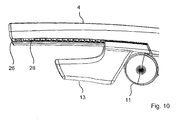
- the display device 1 comprises a spectacle-like frame 2 with a front section 3, which has a nose pad 30, and two ear hooks 4, 5.
- an image module 6 containing, for each eye of a user who touches the display device 1, a display unit 7 with an image-forming element 8 and an imaging optics 9.
- the image module 6 further includes a control unit 10 which drives the display units 7 on the basis of predetermined image data to produce the desired images.
- the image data may be added to the control unit 10 via a signal line, not shown, passing through the right earloop 4.
- An earphone 11, 12 is attached to each earloop 4, 5, which can be pivoted downwards and whose distance from the front section 3 can be adjusted.
- a retaining element 13, 14 is slidably mounted on each earhook, as indicated by the double arrow P1 in Fig. 1 is indicated.
- the two holding elements 13 and 14 are mutually mirror-symmetrical, so that only the retaining element 13 for the right ear will be described in detail below.
- the holding element 13 is substantially L-shaped and has a first section 15 extending downwardly from the right ear hook 4 and a second section 16 adjoining it and extending away from the front section 3.
- the inside 17 ( Fig. 1 ) of the holding member 13 is formed and shaped so as to abut against the region of the temporal bone behind the pinna when a user wears the display device 1 in the manner of glasses. Due to the displaceability of the retaining element 13 relative to the earloop 4, the retaining element 13 can be positioned individually for each user just behind the ear (in the region of the so-called rear ear recess).
- the two areas 18 and 19 are in particular in the sectional views 4 and 7 and in the perspective enlarged view of the holding element 13 in Fig. 6 seen.
- the retaining element 13 can engage well in the rear ear cavity.
- the holding member 13 is further formed so that the inner side 17 in the direction of the second portion 16 in a direction away from the first portion 15 initially has a convex curved portion 20, which is followed by a concave curved portion 21.
- the convex curved portion 20 is for engaging in the rear ear.
- an adjustment of the tapering towards the back head shape By the adjoining concave curve 21, an adjustment of the tapering towards the back head shape. This counteracts a sliding of the display device forward over the nose of the user with a positive wedge effect.
- the concave profile 21 of the second section 16 of the retaining element 13 is also in Fig. 5 seen.
- the inner side 17 is concavely curved in the region of the second portion 17, as in particular from the sectional view of Fig. 9 is apparent. This curvature is chosen so that it is anatomically adapted to the corresponding course of the head.
- the holding element 13 thus has an optimally anatomically adapted shape.
- a solid, complaint-free fit of the display device 1 is achieved, which prevents slipping of the display device over the nose of the user.
- the retaining element 13 has at the upper end of the first section 15 a guide 25 which is arranged in two guide grooves 26, 27 (FIG. Fig. 5 ) engages on both sides of the earloop 4.
- the visible ceremoniessnute 26 is located.
- the guide groove 26 may have a plurality of spaced apart in the longitudinal direction of the earloop 4 locking recesses 28, in which engages a corresponding counterpart on the guide 25.
- This may be, for example, an increase in material (not shown) formed integrally with the guide 25, which, however, positively engages resiliently into the detent recesses 28.
- the two earloop 4 and 5 and the holding elements 13 and 14 may be made of plastic.
- the holding elements 13 and 14 may be either rigid or flexible resilient to ensure in addition to the existing anatomical Anformung an optimal nestling of the holding elements 13 and 14 to the head of the user.
- the locking of the retaining elements 13, 14 relative to the earloop 4, 5 can be done in addition to the locking described by frictional engagement.
- the holding element 13,14 Due to the described design of the holding element 13,14 as a substantially L-shaped, the advantage is achieved that an extremely solid, uncomplicated fit is achieved in the mounted state and at the same time the display device is still expressed compact, since the longer part (second section 16) in parallel to the earloop 4 and away from the front portion 3.
- the two holding elements 13 and 14 can be moved and positioned independently of each other, so that an individual adjustment for the left and right ear of the user is possible.
- the user will be inclined to position the two holding elements 13 and 14 at the same displacement positions on the two earhooks. So you will, for example, the same distance between the holding elements 13 and 14 from the front portion 3 and from the pivot connection of the earhook 4.5 with the front section 3.
- a scale can be mounted on the inside of the earloop 4, 5 in each case.
- the support members 13 and 14 have a mark (e.g., a stroke or corresponding geometry such as an arrow, notch, corner) that can be registered with a desired scale mark on the scale of the respective earloop 4, 5.
- a mark e.g., a stroke or corresponding geometry such as an arrow, notch, corner
- the same or certain different positions for the holding elements 13,14 can be set with this scale left and right.
- the scale can be printed, embossed or molded into the earloop. It is also possible to use the locking recesses 28 as a scale.
- the inscription of the scale can be made, in particular, in length measurements, measured from the swivel joint between the earloop 4, 5 and the front section 3 (eg 60 mm, 65 mm, 70 mm,.
- the labeling can also be done by a numbering of the individual locking recesses 28.
Landscapes
- Physics & Mathematics (AREA)
- General Physics & Mathematics (AREA)
- Optics & Photonics (AREA)
- Health & Medical Sciences (AREA)
- Ophthalmology & Optometry (AREA)
- Eyeglasses (AREA)
- Devices For Indicating Variable Information By Combining Individual Elements (AREA)
Abstract
Description
- Die vorliegende Erfindung betrifft eine Anzeigevorrichtung mit einem Bildmodul zum Erzeugen eines Bildes, einem brillenartigen Gestell, das das Bildmodul trägt und einen Vorderabschnitt mit einer Nasenauflage sowie zwei seitliche Ohrbügel, die am Vorderabschnitt befestigt sind, aufweist. Solche Anzeigevorrichtungen werden häufig HMD-Vorrichtungen (Head-Mounted-Display-Vorrichtungen) genannt. Bei diesen Vorrichtungen besteht aufgrund des Bildmoduls, das durch das brillenartige Gestell getragen wird, die Problematik, daß die Anzeigevorrichtung im Bereich der Nasenauflage ein relativ großes Gewicht aufweist. Daher kann eine solche HMD-Vorrichtung leicht von der Nase nach unten rutschen, so daß der Benutzer das Bild nicht mehr optimal erfassen kann. Insbesondere kann es auch zu Kopfschmerzen kommen, wenn die HMD-Vorrichtung zu tief auf der Nase sitzt.
- Es ist möglich, ein Halteband vorzusehen, das vom freien Ende eines Ohrbügels um den Hinterkopf zum freien Ende des anderen Ohrbügels verläuft. Dabei ist problematisch, daß die Frisur des Benutzers unter Umständen im Bereich des Haltebandes eingedrückt wird. Ferner können sich Haare im Halteband verfangen. Auch darf die Länge des Haltebandes, das in der Regel ein Gummiband ist, nicht zu kurz oder zu lang sein. Auch tritt häufig die Schwierigkeit auf, daß das Halteband zu stark gespannt ist, so daß auf Dauer ein unangenehmer Druck der Anzeigevorrichtungen auf die Nase des Benutzers erfolgt.
- Ausgehend hiervon ist es Aufgabe der Erfindung, eine Anzeigevorrichtung der eingangs genannten Art so weiterzubilden, daß ein fester und gleichzeitig beschwerdefreier Sitz der Anzeigevorrichtung beim Tragen auf dem Kopf eines Benutzers gewährleistet werden kann.
- Die Aufgabe wird bei einer Anzeigevorrichtung der eingangs genannten Art dadurch gelöst, daß zumindest an einem der Ohrbügel ein Halteelement verschiebbar befestigt ist, das einen sich vom Ohrbügel nach unten erstreckenden ersten Abschnitt aufweist.
- Durch die Verschiebbarkeit des Halteelements ist es möglich, das Halteelement für jeden Benutzer individuell optimal hinter dem Ohr im Bereich des Schläfenbeines zu positionieren.
- Insbesondere ist das Halteelement in Längsrichtung des Ohrbügels verschiebbar. Damit kann die Position des Halteelements für jeden Benutzer individuell so angepaßt werden, daß das Haltelement genau hinter dem Ohr im Schläfenbeinbereich bei aufgesetzter Anzeigevorrichtung anliegt.
- Ferner kann das Halteelement einen mit dem unteren Ende des ersten Abschnittes verbundenen zweiten Abschnitt aufweisen, wobei sich der zweite Abschnitt vom unteren Ende in einer Richtung weg vom Vorderabschnitt erstreckt.
- Da sich der zweite Abschnitt vom unteren Ende des ersten Abschnitts in einer Richtung weg vom Vorderabschnitt erstreckt, kann ein großer Auflagebereich mit dem Halteelement realisiert werden. Gleichzeitig führt dies nicht zu einem erhöhten Platzbedarf der HMD-Vorrichtung, da der zweite Abschnitt bevorzugt im wesentlichen parallel zum Ohrbügel verläuft. Würde der zweite Abschnitt in gleicher Weise wie der erste Abschnitt nach unten verlaufen, würde sich das Halteelement unerwünscht weit vom Ohrbügel nach unten erstrecken.
- Die Innenseite des Halteelementes, die im auf den Kopf eines Benutzers aufgesetzten Zustand der Anzeigevorrichtung hinter dem Ohr des Benutzers am Kopf anliegt, kann so ausgebildet sein, daß sie im Bereich des ersten Abschnitts in eine Richtung vom Ohrbügel weg (also vom Ohrbügel nach unten) zunächst eine konvexe Krümmung aufweist, die in eine konkave Krümmung übergeht. Ferner kann die Innenseite im Bereich des zweiten Abschnitts in einer Richtung vom ersten Abschnitt weg eine konvexe Krümmung aufweisen, die in eine konkave Krümmung übergeht. Durch die beschriebene Ausbildung der Innenseite im Bereich des ersten Abschnitts kann das Halteelement optimal in die Hinterohrmulde (der Bereich des Schläfenbeins hinter dem Gehörgang) eingreifen. Durch die konvexe Krümmung im Bereich des zweiten Abschnitts führt dies zu einem regelrechten Einhaken des Halteelements in die Hinterohrmulde. Die darauf folgende konvexe Krümmung des zweiten Abschnittes ist eine Anpassung an die sich nach hinten wieder verjüngende Kopfform, wodurch eine positive Keilwirkung erreicht wird, die einer nach vorne über die Nase rutschenden Anzeigevorrichtung entgegenwirkt.
- Ferner kann die Innenseite des Halteelements im Bereich des zweiten Abschnitts in einer Richtung vom Ohrbügel weg konkav gekrümmt sein. Dies ist eine weitere anatomische Anpassung der Ausbildung der Innenseite an die Hinterohrmulde.
- Die beiden Abschnitte des Halteelementes können im wesentlichen L-förmig angeordnet sein. Damit wird ein einerseits kompaktes Halteelement bereitgestellt, das andererseits einen optimalen Halt der Anzeigevorrichtung gewährleisten kann.
- Insbesondere weist die Anzeigevorrichtung einen Arretiermechanismus auf, mit dem eine eingestellte Verschiebeposition des Halteelementes relativ zum Ohrbügel arretierbar ist. Natürlich sind mehrere verschiedene Verschiebepositionen möglich, so daß eine individuelle Anpassung an den jeweiligen Benutzer erfolgen kann. Die Verschiebepositionen können entweder vorgegebene Verschiebepositionen mit vorbestimmten Abständen zueinander sein oder es ist eine kontinuierliche Verschiebung möglich.
- Der Arretiermechanismus kann beispielsweise mittels Form- und/oder Reibschluß erfolgen.
- Ferner ist es möglich, das Halteelement teleskopartig mit dem Brillenbügel zu verbinden, um die gewünschte Verschiebbarkeit zu erreichen.
- Des weiteren ist das Halteelement bevorzugt derart verschiebbar zum Ohrbügel, daß nur eine Verschiebung in Längsrichtung des Ohrbügels möglich ist. Eine Drehung um die Längsrichtung wird dadurch beispielsweise verhindert.
- Das Halteelement kann einen Führungsschlitten aufweisen, der in zwei Führungsnuten, die sich in Längsrichtung an beiden Seiten des Ohrbügels erstrecken, eingreift.
- Das Halteelement kann relativ dick und starr sein.
- Ferner kann das Halteelement in einer Richtung quer zum Ohrbügel elastisch vorgespannt sein. Wenn das Halteelement starr ist, kann eine Federvorspannung realisiert sein. Alternativ ist es möglich, daß die elastische Vorspannung durch die Eigenelastizität des Halteelements realisiert ist.
- Insbesondere kann an jedem Ohrbügel der Anzeigevorrichtung jeweils ein Halteelement verschiebbar befestigt sein, das eines oder mehrere der oben beschriebenen Merkmale aufweist.
- Natürlich ist das Halteelement für das rechte Ohr an die entsprechende Anatomie des Kopfes im Bereich des rechten Ohrs und das Halteelement für das linke Ohr an die entsprechende Anatomie des Kopfes im Bereich des linken Ohrs angepaßt.
- Das Bildmodul der Anzeigevorrichtung zum Erzeugen des Bildes kann das Bild als virtuelles Bild so erzeugen, daß es ein Benutzer in einem vorbestimmten Abstand vor dem Auge wahrnehmen kann, wenn er die Anzeigevorrichtung auf dem Kopf in Art einer Brille trägt.
- Insbesondere kann das Bildmodul wie bei bekannten HMD-Vorrichtungen ausgebildet werden.
- Ferner kann das Bildmodul eine Steuereinrichtung aufweisen, die auf der Basis von vorgegebenen Bilddaten ein bilderzeugendes Element des Bildmoduls so ansteuert, daß das gewünschte Bild erzeugt wird. Das Bildmodul kann ferner eine Abbildungsoptik zur Abbildung des mittels dem bilderzeugenden Element erzeugten Bildes enthalten.
- Es versteht sich, daß die vorstehend genannten und die nachstehend noch zu erläuternden Merkmale nicht nur in den angegebenen Kombinationen, sondern auch in anderen Kombinationen oder in Alleinstellung einsetzbar sind, ohne den Rahmen der vorliegenden Erfindung zu verlassen.
- Nachfolgend wird die Erfindung beispielsweise anhand der beigefügten Zeichnungen, die auch erfindungswesentliche Merkmale offenbaren, noch näher erläutert. Es zeigen:
- Fig. 1
- eine perspektivische Ansicht einer Ausführungsform der erfindungsgemäßen Anzeigevorrichtung;
- Fig. 2
- eine schematische Draufsicht der Anzeigevorrichtung von
Fig. 1 ; - Fig. 3
- eine Seitenansicht der Anzeigevorrichtung von
Fig. 1 ; - Fig. 4
- eine Schnittdarstellung entlang der Schnittlinie A-A von
Fig. 3 ; - Fig. 5
- eine Ansicht von hinten der Anzeigevorrichtung von
Fig.1 ; - Fig. 6
- eine vergrößerte perspektivische Darstellung des Halteelementes 13;
- Fig. 7
- eine Schnittdarstellung entlang der Schnittlinie B-B in
Fig. 6 ; - Fig. 8
- eine Schnittdarstellung entlang der Schnittlinie C-C in
Fig. 6 ; - Fig. 9
- eine Schnittdarstellung entlang der Schnittlinie D-D in
Fig. 6 , und - Fig. 10
- eine vergrößerte Darstellung eines Ausschnitts des Ohrbügels 4 zusammen mit dem Halteelement 13.
- Bei der in den in den
Figuren 1-10 gezeigten Ausführungsform umfaßt die erfindungsgemäße Anzeigevorrichtung 1 ein brillenartiges Gestell 2 mit einem Vorderabschnitt 3, der eine Nasenauflage 30 aufweist, und zwei Ohrbügeln 4, 5. - Im Vorderabschnitt 3 ist, wie in der schematischen Darstellung von
Fig. 2 ersichtlich ist, ein Bildmodul 6 enthalten, das für jedes Auge eines Benutzers, der die Anzeigevorrichtung 1 aufsetzt, eine Anzeigeeinheit 7 mit einem bilderzeugenden Element 8 und einer Abbildungsoptik 9 aufweist. Das Bildmodul 6 enthält ferner eine Steuereinheit 10, die die Anzeigeinheiten 7 auf der Basis vorgegebener Bilddaten ansteuert, um die gewünschten Bilder zu erzeugen. Die Bilddaten können beispielsweise über eine nicht gezeigte Signalleitung, die durch den rechten Ohrbügel 4 verläuft, der Steuereinheit 10 zugefügt werden. - An jedem Ohrbügel 4, 5 ist jeweils ein Ohrhörer 11, 12 befestigt, der nach unten geschwenkt und dessen Abstand vom Vorderabschnitt 3 eingestellt werden kann.
- Ferner ist an jedem Ohrbügel ein Halteelement 13, 14 verschiebbar befestigt, wie durch den Doppelpfeil P1 in
Fig. 1 angedeutet ist. Die beiden Halteelemente 13 und 14 sind zueinander spiegelsymmetrisch ausgebildet, so daß nachfolgend im Detail nur das Halteelement 13 für das rechte Ohr beschrieben wird. - Das Halteelement 13 ist im wesentlichen L-förmig ausgebildet und weist einen sich vom rechten Ohrbügel 4 nach unten erstreckenden ersten Abschnitt 15 sowie einen sich daran anschließenden und vom Vorderabschnitt 3 wegerstreckenden zweiten Abschnitt 16 auf.
- Die Innenseite 17 (
Fig. 1 ) des Halteelements 13 ist so ausgebildet und geformt, daß sie an den Bereich des Schläfenbeins hinter der Ohrmuschel anliegt, wenn ein Benutzer die Anzeigevorrichtung 1 in Art einer Brille trägt. Aufgrund der Verschiebbarkeit des Halteelements 13 relativ zum Ohrbügel 4 kann man individuell für jeden Benutzer das Halteelement 13 genau hinter dem Ohr (im Bereich der sogenannten Hinterohrmulde) positionieren. - Um ein möglichst optimales Anliegen des Halteelements 13 an der Hinterohrmulde zu realisieren, weist die Innenseite 17 im Bereich des ersten Abschnittes 15 in einer Richtung vom Ohrbügel 4 nach unten zunächst einen konvex gekrümmten Bereich 18 auf, an den sich ein konkav gekrümmter Bereich 19 anschließt. Die beiden Bereiche 18 und 19 sind insbesondere in den Schnittdarstellungen 4 und 7 sowie in der perspektivischen vergrößerten Darstellung des Halteelementes 13 in
Fig. 6 ersichtlich. Durch diese Ausbildung des ersten Abschnitts 15 kann das Halteelement 13 gut in die Hinterohrmulde eingreifen. - Das Halteelement 13 ist ferner so ausgebildet, daß die Innenseite 17 im Bereich des zweiten Abschnitts 16 in einer Richtung vom ersten Abschnitt 15 weg zunächst einen konvex gekrümmten Bereich 20 aufweist, dem sich ein konkav gekrümmter Bereich 21 anschließt. Der konvex gekrümmte Bereich 20 dient zum Eingreifen in die Hinterohrmulde. Durch den sich daran anschließenden konkav gekrümmten Verlauf 21 erfolgt eine Anpassung der sich nach hinten verjüngenden Kopfform. Dadurch wird mit einer positiven Keilwirkung einem Rutschen der Anzeigevorrichtung nach vorne über die Nase des Benutzers entgegengewirkt. Der konkave Verlauf 21 des zweiten Abschnitts 16 des Halteelements 13 ist auch in
Fig. 5 ersichtlich. - Senkrecht zur Längsrichtung des zweiten Abschnitts 16 ist die Innenseite 17 im Bereich des zweiten Abschnitts 17 konkav gekrümmt, wie insbesondere aus der Schnittdarstellung von
Fig. 9 ersichtlich ist. Diese Krümmung ist so gewählt, daß sie anatomisch an den entsprechenden Verlauf des Kopfes angepaßt ist. - Insgesamt weist das Halteelement 13 somit eine optimal anatomisch angepaßte Form auf. Damit wird ein fester, beschwerdefreier Sitz der Anzeigevorrichtung 1 erreicht, was ein Herunterrutschen der Anzeigevorrichtung über die Nase des Benutzers verhindert.
- Um die Verschiebbarkeit des Halteelements 13 relativ zum Ohrbügel 4 zu gewährleisten, weist das Halteelement 13 an dem oberen Ende des ersten Abschnitts 15 eine Führung 25 auf, die in zwei Führungsnuten 26,27 (
Fig. 5 ) auf beiden Seiten des Ohrbügels 4 eingreift. In der vergrößerten Detaildarstellung vonFig. 10 ist die sichtbare Führungsnute 26 eingezeichnet. - Für eine sichere Arretierung der gewählten Verschiebeposition des Halteelements 13 relativ zum Ohrbügel 4 ist ein Rastmechanismus vorgesehen. So kann die Führungsnute 26 mehrere voneinander in Längsrichtung des Ohrbügels 4 beabstandete Rastvertiefungen 28 aufweisen, in die ein entsprechendes Gegenstück an der Führung 25 eingreift. Dabei kann es sich beispielsweise um eine integral mit der Führung 25 ausgebildete Materialerhöhung (nicht gezeigt) handeln, die formschlüssig aber federnd in die Rastvertiefungen 28 eingreift. Es ist jedoch auch möglich, ein separates Federelement (nicht gezeigt) an der Führung 25 vorzusehen.
- Natürlich ist es auch möglich, die Rastvertiefungen am Halteelement 14 auszubilden und das entsprechende eingreifende Gegenstück am Ohrbügel 4 vorzusehen.
- Um das Gewicht der Anzeigevorrichtung möglichst gering zu halten, können insbesondere der Vorderabschnitt 3, die beiden Ohrbügel 4 und 5 sowie die Halteelemente 13 und 14 aus Kunststoff hergestellt sein.
- Die Halteelemente 13 und 14 können entweder starr ausgebildet sein oder auch flexibel federnd, um zusätzlich zu der schon vorhandenen anatomischen Anformung ein optimales Anschmiegen der Halteelemente 13 und 14 an den Kopf des Benutzers zu gewährleisten.
- Die Arretierung der Halteelemente 13, 14 relativ zum Ohrbügel 4, 5 kann neben der beschriebenen Verrastung auch durch Reibschluß erfolgen. Insbesondere ist es möglich, eine Fixierung durch eine Schraube zu erzielen, die bei der gewünschten Verschiebeposition angezogen wird.
- Durch die beschriebene Ausbildung des Halteelements 13,14 als wesentlich L-förmig wird der Vorteil erreicht, daß ein außerordentlich fester, beschwerdefreier Sitz im aufgesetzten Zustand erreicht wird und gleichzeitig die Anzeigevorrichtung noch äußert kompakt ist, da der längere Teil (zweiter Abschnitt 16) parallel zum Ohrbügel 4 und vom Vorderabschnitt 3 weg verläuft.
- Bei der erfindungsgemäßen Anzeigevorrichtung können die beiden Halteelemente 13 und 14 voneinander unabhängig verschoben und positioniert werden, so daß eine individuelle Anpassung für das linke und rechte Ohr des Benutzers möglich ist. In der Regel wird der Benutzer dazu geneigt sein, die beiden Halteelemente 13 und 14 an gleichen Verschiebepositionen an den beiden Ohrbügeln zu positionieren. Man wird also zum Beispiel den Abstand der Halteelemente 13 und 14 vom Vorderabschnitt 3 beziehungsweise von der Drehgelenkverbindung der Ohrbügel 4,5 mit dem Vorderabschnitt 3 gleich wählen. Um dies zu erleichtern, kann auf der Innenseite der Ohrbügel 4,5 jeweils eine Skala angebracht werden. Die Halteelemente 13 und 14 weisen eine Markierung (z.B. einen Strich oder eine entsprechende Geometrie wie beispielsweise Pfeil, Kerbe, Ecke) auf, die mit einem gewünschten Skalenstrich der Skala des jeweiligen Ohrbügels 4,5 zur Deckung gebracht werden kann. Somit kann mit dieser Skala links und rechts die gleiche oder auch bestimmte unterschiedliche Positionen für die Halteelemente 13,14 eingestellt werden.
- Die Skala kann gedruckt, geprägt oder im Ohrbügel angeformt sein. Es ist auch möglich, die Rastvertiefungen 28 als Skala zu verwenden. Die Beschriftung der Skala kann insbesondere in Längenmaßangaben gemessen vom Drehgelenk zwischen dem Ohrbügel 4,5 und dem Vorderabschnitt 3 erfolgen (z. B. 60 mm, 65 mm, 70 mm,...). Die Beschriftung kann auch durch eine Numerierung der einzelnen Rastvertiefungen 28 erfolgen.
- Anstatt der schienenartigen Führung 25 in Verbindung mit den Rastnuten 26 und 27 ist es möglich, die Halteelemente 13 und 14 so auszubilden, daß sie teleskopartig mit dem Ohrbügel 4, 5 verbunden sind.
Claims (12)
- Anzeigevorrichtung mit einem Bildmodul (6) zum Erzeugen eines Bildes, einem brillenartigen Gestell (2), das das Bildmodul (6) trägt und einen Vorderabschnitt (3) mit einer Nasenauflage (30) sowie zwei seitliche Ohrbügel (4,5), die am Vorderabschnitt (3) befestigt sind, aufweist,
dadurch gekennzeichnet, daß zumindest an einem der Ohrbügel (4, 5) ein Halteelement (13,14) verschiebbar befestigt ist, das einen sich vom Ohrbügel (4,5) nach unten erstreckenden ersten Abschnitt (15) aufweist. - Anzeigevorrichtung nach Anspruch 1, dadurch gekennzeichnet, daß das Halteelement (13,14) entlang der Längsrichtung des Ohrbügels (4,5) verschiebbar ist.
- Anzeigevorrichtung nach einem der obigen Ansprüche, dadurch gekennzeichnet, daß die Innenseite (17) des Halteelements (13,14), die im auf den Kopf eines Benutzers aufgesetzten Zustand der Anzeigevorrichtung hinter dem Ohr des Benutzers am Kopf anliegt, im Bereich des ersten Abschnitts in einer Richtung vom Ohrbügel (4,5) weg zunächst eine konvexe Krümmung aufweist, die in eine konkave Krümmung übergeht.
- Anzeigevorrichtung nach einem der obigen Ansprüche, dadurch gekennzeichnet, daß das Halteelement (13, 14) einen mit dem unteren Ende des ersten Abschnitts (15) verbundenen zweiten Abschnitt (16) aufweist, wobei sich der zweite Abschnitt (16) vom unteren Ende in einer Richtung weg vom Vorderabschnitt (3) erstreckt.
- Anzeigevorrichtung nach Anspruch 4, dadurch gekennzeichnet, daß die Innenseite (17) des Halteelements (13, 14), die im auf dem Kopf aufgesetzten Zustand der Anzeigevorrichtung hinter dem Ohr des Benutzers am Ohr anliegt, im Bereich des zweiten Abschnitts (16) in einer Richtung vom ersten Abschnitt (15) weg eine konvexe Krümmung aufweist, die in eine konkave Krümmung übergeht.
- Anzeigevorrichtung nach Anspruch 4 oder 5, dadurch gekennzeichnet, daß die Innenseite des Halteelements (13,14), die im auf den Kopf eines Benutztes aufgesetzten Zustand der Anzeigevorrichtung hinter dem Ohr des Benutzers am Kopf anliegt, im Bereich des zweiten Abschnitts in einer Richtung vom Ohrbügel weg eine konkave Krümmung aufweist.
- Anzeigevorrichtung nach einem der Ansprüche 4 bis 6, dadurch gekennzeichnet, daß die beiden Abschnitte (15,16) des Halteelementes (13,14) im wesentlichen L-förmig angeordnet sind.
- Anzeigevorrichtung nach einem der obigen Ansprüche, dadurch gekennzeichnet, daß ein Arretiermechanismus vorgesehen ist, mit dem eine eingestellte Verschiebeposition des Halteelementes (13,14) relativ zum Ohrbügel (4,5) arretierbar ist.
- Anzeigevorrichtung nach Anspruch 8, dadurch gekennzeichnet, daß der Arretiermechanismus eine Arretierung mittels Form- und/oder Reibschluß bewirkt.
- Anzeigevorrichtung nach einem der obigen Ansprüche, dadurch gekennzeichnet, daß das Halteelement (13,14) in einer Richtung quer zum Ohrbügel elastisch vorgespannt ist.
- Anzeigevorrichtung nach Anspruch 10, dadurch gekennzeichnet, daß die elastische Vorspannung durch die Eigenelastizität des Halteelements (13,14) realisiert ist.
- Anzeigvorrichtung nach einem der obigen Ansprüche, dadurch gekennzeichnet, daß an jedem Ohrbügel (4, 5) jeweils ein Halteelement (13, 14) verschiebbar befestigt ist.
Applications Claiming Priority (1)
| Application Number | Priority Date | Filing Date | Title |
|---|---|---|---|
| DE102007053282A DE102007053282A1 (de) | 2007-11-08 | 2007-11-08 | Anzeigevorrichtung |
Publications (3)
| Publication Number | Publication Date |
|---|---|
| EP2058689A2 true EP2058689A2 (de) | 2009-05-13 |
| EP2058689A3 EP2058689A3 (de) | 2010-02-10 |
| EP2058689B1 EP2058689B1 (de) | 2011-10-12 |
Family
ID=39986642
Family Applications (1)
| Application Number | Title | Priority Date | Filing Date |
|---|---|---|---|
| EP08015240A Active EP2058689B1 (de) | 2007-11-08 | 2008-08-28 | Anzeigevorrichtung |
Country Status (4)
| Country | Link |
|---|---|
| US (1) | US8384618B2 (de) |
| EP (1) | EP2058689B1 (de) |
| AT (1) | ATE528682T1 (de) |
| DE (2) | DE102007053282A1 (de) |
Families Citing this family (2)
| Publication number | Priority date | Publication date | Assignee | Title |
|---|---|---|---|---|
| DE102008049338A1 (de) | 2008-09-29 | 2010-04-08 | Carl Zeiss Ag | Anzeigevorrichtung |
| CN107005667B (zh) * | 2014-12-15 | 2020-04-10 | 奥林巴斯株式会社 | 可佩戴设备用支承部件 |
Family Cites Families (9)
| Publication number | Priority date | Publication date | Assignee | Title |
|---|---|---|---|---|
| FR1295891A (fr) * | 1961-07-25 | 1962-06-08 | Perfectionnements aux montures de lunettes | |
| US5880773A (en) * | 1991-12-27 | 1999-03-09 | Sony Corporation | Head mounted display configured to a user's physical features |
| JPH0628831U (ja) * | 1992-09-16 | 1994-04-15 | 株式会社キャットアイ | 眼 鏡 |
| US6448944B2 (en) * | 1993-10-22 | 2002-09-10 | Kopin Corporation | Head-mounted matrix display |
| JP3352212B2 (ja) * | 1994-03-17 | 2002-12-03 | オリンパス光学工業株式会社 | 頭部装着型映像表示装置 |
| WO1999023524A1 (en) * | 1997-10-30 | 1999-05-14 | The Microoptical Corporation | Eyeglass interface system |
| JP3897200B2 (ja) | 1997-11-07 | 2007-03-22 | Hoya株式会社 | 顔面計測器 |
| JPH11237583A (ja) | 1998-02-20 | 1999-08-31 | Canon Inc | ヘッドマウントディスプレイ装置 |
| JP2005534269A (ja) * | 2002-07-26 | 2005-11-10 | オークレイ・インコーポレイテッド | 無線対話式ヘッドセット |
-
2007
- 2007-11-08 DE DE102007053282A patent/DE102007053282A1/de not_active Withdrawn
-
2008
- 2008-08-28 AT AT08015240T patent/ATE528682T1/de active
- 2008-08-28 EP EP08015240A patent/EP2058689B1/de active Active
- 2008-09-16 DE DE202008012265U patent/DE202008012265U1/de not_active Expired - Lifetime
- 2008-10-31 US US12/262,756 patent/US8384618B2/en active Active
Non-Patent Citations (1)
| Title |
|---|
| None |
Also Published As
| Publication number | Publication date |
|---|---|
| US8384618B2 (en) | 2013-02-26 |
| US20090121971A1 (en) | 2009-05-14 |
| DE202008012265U1 (de) | 2008-11-13 |
| DE102007053282A1 (de) | 2009-05-14 |
| EP2058689A3 (de) | 2010-02-10 |
| ATE528682T1 (de) | 2011-10-15 |
| EP2058689B1 (de) | 2011-10-12 |
Similar Documents
| Publication | Publication Date | Title |
|---|---|---|
| EP2056157B1 (de) | Anzeigevorrichtung | |
| DE102012003564B3 (de) | Vorrichtung zur Verbesserung der Atmung einer Person | |
| DE19652286B4 (de) | Schutzbrille | |
| DE102021119617A1 (de) | Kopfaufhängung für eine Kopfbedeckung und Kopfbedeckung mit einer Kopfaufhängung | |
| DE19652285B4 (de) | Schutzbrille | |
| DE102015221744A1 (de) | Funktionales Kopfband mit integriertem Polsterband | |
| DE102010033343A1 (de) | Schlafmaske/-brille | |
| DE2540396A1 (de) | Atemschutzgeraet fuer brillentraeger | |
| EP2058689B1 (de) | Anzeigevorrichtung | |
| WO2015158832A1 (de) | Anzeigevorrichtung und einstellverfahren für eine solche anzeigevorrichtung | |
| DE20108520U1 (de) | Schwimmbrille | |
| EP0415925B1 (de) | Bügel für brillengestell | |
| DE102008049338A1 (de) | Anzeigevorrichtung | |
| EP3806786B1 (de) | Unterkieferprotrusionseinrichtung | |
| DE202013103201U1 (de) | Schwimmbrille | |
| EP2734891B1 (de) | Brille | |
| EP1555566A1 (de) | Elastische Brille | |
| DE102019101412B4 (de) | Schutzhelm mit Verstellmechanismus | |
| DE102021102303B3 (de) | Adapter und Set aus wenigstens zwei Adaptern | |
| DE202020102794U1 (de) | Mundschutz für Brillenträger | |
| DE8519305U1 (de) | Skibrille mit optischem Einsatz | |
| DE102020204978B4 (de) | Gesichtsschutz | |
| DE20015202U1 (de) | Kombinationsbrille | |
| DE102007013068A1 (de) | Gesichtsbogen | |
| DE9205717U1 (de) | Brillengestell |
Legal Events
| Date | Code | Title | Description |
|---|---|---|---|
| PUAI | Public reference made under article 153(3) epc to a published international application that has entered the european phase |
Free format text: ORIGINAL CODE: 0009012 |
|
| AK | Designated contracting states |
Kind code of ref document: A2 Designated state(s): AT BE BG CH CY CZ DE DK EE ES FI FR GB GR HR HU IE IS IT LI LT LU LV MC MT NL NO PL PT RO SE SI SK TR |
|
| AX | Request for extension of the european patent |
Extension state: AL BA MK RS |
|
| PUAL | Search report despatched |
Free format text: ORIGINAL CODE: 0009013 |
|
| AK | Designated contracting states |
Kind code of ref document: A3 Designated state(s): AT BE BG CH CY CZ DE DK EE ES FI FR GB GR HR HU IE IS IT LI LT LU LV MC MT NL NO PL PT RO SE SI SK TR |
|
| AX | Request for extension of the european patent |
Extension state: AL BA MK RS |
|
| RIC1 | Information provided on ipc code assigned before grant |
Ipc: G02B 27/01 20060101AFI20090312BHEP Ipc: G02B 27/00 20060101ALN20100105BHEP Ipc: G02C 5/14 20060101ALI20100105BHEP |
|
| 17P | Request for examination filed |
Effective date: 20100728 |
|
| AKX | Designation fees paid |
Designated state(s): AT BE BG CH CY CZ DE DK EE ES FI FR GB GR HR HU IE IS IT LI LT LU LV MC MT NL NO PL PT RO SE SI SK TR |
|
| 17Q | First examination report despatched |
Effective date: 20101021 |
|
| GRAP | Despatch of communication of intention to grant a patent |
Free format text: ORIGINAL CODE: EPIDOSNIGR1 |
|
| RIC1 | Information provided on ipc code assigned before grant |
Ipc: G02B 27/00 20060101ALN20110331BHEP Ipc: G02C 5/14 20060101ALI20110331BHEP Ipc: G02B 27/01 20060101AFI20110331BHEP |
|
| RIN1 | Information on inventor provided before grant (corrected) |
Inventor name: ENGLER, BERTOLD Inventor name: BECK, KLAUS Inventor name: ROTTENKOLBER, BIRGIT Inventor name: KARUTZ, FRANK-OLIVER, DR. Inventor name: WURSCHER, NORBERT |
|
| GRAS | Grant fee paid |
Free format text: ORIGINAL CODE: EPIDOSNIGR3 |
|
| GRAA | (expected) grant |
Free format text: ORIGINAL CODE: 0009210 |
|
| AK | Designated contracting states |
Kind code of ref document: B1 Designated state(s): AT BE BG CH CY CZ DE DK EE ES FI FR GB GR HR HU IE IS IT LI LT LU LV MC MT NL NO PL PT RO SE SI SK TR |
|
| REG | Reference to a national code |
Ref country code: GB Ref legal event code: FG4D Free format text: NOT ENGLISH |
|
| REG | Reference to a national code |
Ref country code: CH Ref legal event code: NV Representative=s name: KELLER & PARTNER PATENTANWAELTE AG Ref country code: CH Ref legal event code: EP |
|
| REG | Reference to a national code |
Ref country code: IE Ref legal event code: FG4D |
|
| REG | Reference to a national code |
Ref country code: DE Ref legal event code: R096 Ref document number: 502008005127 Country of ref document: DE Effective date: 20120105 |
|
| REG | Reference to a national code |
Ref country code: NL Ref legal event code: VDEP Effective date: 20111012 |
|
| LTIE | Lt: invalidation of european patent or patent extension |
Effective date: 20111012 |
|
| PG25 | Lapsed in a contracting state [announced via postgrant information from national office to epo] |
Ref country code: NO Free format text: LAPSE BECAUSE OF FAILURE TO SUBMIT A TRANSLATION OF THE DESCRIPTION OR TO PAY THE FEE WITHIN THE PRESCRIBED TIME-LIMIT Effective date: 20120112 Ref country code: LT Free format text: LAPSE BECAUSE OF FAILURE TO SUBMIT A TRANSLATION OF THE DESCRIPTION OR TO PAY THE FEE WITHIN THE PRESCRIBED TIME-LIMIT Effective date: 20111012 Ref country code: IS Free format text: LAPSE BECAUSE OF FAILURE TO SUBMIT A TRANSLATION OF THE DESCRIPTION OR TO PAY THE FEE WITHIN THE PRESCRIBED TIME-LIMIT Effective date: 20120212 |
|
| REG | Reference to a national code |
Ref country code: IE Ref legal event code: FD4D |
|
| PG25 | Lapsed in a contracting state [announced via postgrant information from national office to epo] |
Ref country code: NL Free format text: LAPSE BECAUSE OF FAILURE TO SUBMIT A TRANSLATION OF THE DESCRIPTION OR TO PAY THE FEE WITHIN THE PRESCRIBED TIME-LIMIT Effective date: 20111012 Ref country code: SE Free format text: LAPSE BECAUSE OF FAILURE TO SUBMIT A TRANSLATION OF THE DESCRIPTION OR TO PAY THE FEE WITHIN THE PRESCRIBED TIME-LIMIT Effective date: 20111012 Ref country code: LV Free format text: LAPSE BECAUSE OF FAILURE TO SUBMIT A TRANSLATION OF THE DESCRIPTION OR TO PAY THE FEE WITHIN THE PRESCRIBED TIME-LIMIT Effective date: 20111012 Ref country code: GR Free format text: LAPSE BECAUSE OF FAILURE TO SUBMIT A TRANSLATION OF THE DESCRIPTION OR TO PAY THE FEE WITHIN THE PRESCRIBED TIME-LIMIT Effective date: 20120113 Ref country code: HR Free format text: LAPSE BECAUSE OF FAILURE TO SUBMIT A TRANSLATION OF THE DESCRIPTION OR TO PAY THE FEE WITHIN THE PRESCRIBED TIME-LIMIT Effective date: 20111012 Ref country code: SI Free format text: LAPSE BECAUSE OF FAILURE TO SUBMIT A TRANSLATION OF THE DESCRIPTION OR TO PAY THE FEE WITHIN THE PRESCRIBED TIME-LIMIT Effective date: 20111012 Ref country code: PT Free format text: LAPSE BECAUSE OF FAILURE TO SUBMIT A TRANSLATION OF THE DESCRIPTION OR TO PAY THE FEE WITHIN THE PRESCRIBED TIME-LIMIT Effective date: 20120213 |
|
| PG25 | Lapsed in a contracting state [announced via postgrant information from national office to epo] |
Ref country code: CY Free format text: LAPSE BECAUSE OF FAILURE TO SUBMIT A TRANSLATION OF THE DESCRIPTION OR TO PAY THE FEE WITHIN THE PRESCRIBED TIME-LIMIT Effective date: 20111012 |
|
| PG25 | Lapsed in a contracting state [announced via postgrant information from national office to epo] |
Ref country code: SK Free format text: LAPSE BECAUSE OF FAILURE TO SUBMIT A TRANSLATION OF THE DESCRIPTION OR TO PAY THE FEE WITHIN THE PRESCRIBED TIME-LIMIT Effective date: 20111012 Ref country code: EE Free format text: LAPSE BECAUSE OF FAILURE TO SUBMIT A TRANSLATION OF THE DESCRIPTION OR TO PAY THE FEE WITHIN THE PRESCRIBED TIME-LIMIT Effective date: 20111012 Ref country code: IE Free format text: LAPSE BECAUSE OF FAILURE TO SUBMIT A TRANSLATION OF THE DESCRIPTION OR TO PAY THE FEE WITHIN THE PRESCRIBED TIME-LIMIT Effective date: 20111012 Ref country code: BG Free format text: LAPSE BECAUSE OF FAILURE TO SUBMIT A TRANSLATION OF THE DESCRIPTION OR TO PAY THE FEE WITHIN THE PRESCRIBED TIME-LIMIT Effective date: 20120112 Ref country code: DK Free format text: LAPSE BECAUSE OF FAILURE TO SUBMIT A TRANSLATION OF THE DESCRIPTION OR TO PAY THE FEE WITHIN THE PRESCRIBED TIME-LIMIT Effective date: 20111012 Ref country code: CZ Free format text: LAPSE BECAUSE OF FAILURE TO SUBMIT A TRANSLATION OF THE DESCRIPTION OR TO PAY THE FEE WITHIN THE PRESCRIBED TIME-LIMIT Effective date: 20111012 |
|
| PLBE | No opposition filed within time limit |
Free format text: ORIGINAL CODE: 0009261 |
|
| STAA | Information on the status of an ep patent application or granted ep patent |
Free format text: STATUS: NO OPPOSITION FILED WITHIN TIME LIMIT |
|
| PG25 | Lapsed in a contracting state [announced via postgrant information from national office to epo] |
Ref country code: IT Free format text: LAPSE BECAUSE OF FAILURE TO SUBMIT A TRANSLATION OF THE DESCRIPTION OR TO PAY THE FEE WITHIN THE PRESCRIBED TIME-LIMIT Effective date: 20111012 Ref country code: RO Free format text: LAPSE BECAUSE OF FAILURE TO SUBMIT A TRANSLATION OF THE DESCRIPTION OR TO PAY THE FEE WITHIN THE PRESCRIBED TIME-LIMIT Effective date: 20111012 Ref country code: PL Free format text: LAPSE BECAUSE OF FAILURE TO SUBMIT A TRANSLATION OF THE DESCRIPTION OR TO PAY THE FEE WITHIN THE PRESCRIBED TIME-LIMIT Effective date: 20111012 |
|
| 26N | No opposition filed |
Effective date: 20120713 |
|
| REG | Reference to a national code |
Ref country code: DE Ref legal event code: R097 Ref document number: 502008005127 Country of ref document: DE Effective date: 20120713 |
|
| BERE | Be: lapsed |
Owner name: CARL ZEISS A.G. Effective date: 20120831 |
|
| PG25 | Lapsed in a contracting state [announced via postgrant information from national office to epo] |
Ref country code: MC Free format text: LAPSE BECAUSE OF NON-PAYMENT OF DUE FEES Effective date: 20120831 |
|
| PG25 | Lapsed in a contracting state [announced via postgrant information from national office to epo] |
Ref country code: ES Free format text: LAPSE BECAUSE OF FAILURE TO SUBMIT A TRANSLATION OF THE DESCRIPTION OR TO PAY THE FEE WITHIN THE PRESCRIBED TIME-LIMIT Effective date: 20120123 |
|
| PG25 | Lapsed in a contracting state [announced via postgrant information from national office to epo] |
Ref country code: BE Free format text: LAPSE BECAUSE OF NON-PAYMENT OF DUE FEES Effective date: 20120831 |
|
| PG25 | Lapsed in a contracting state [announced via postgrant information from national office to epo] |
Ref country code: FI Free format text: LAPSE BECAUSE OF FAILURE TO SUBMIT A TRANSLATION OF THE DESCRIPTION OR TO PAY THE FEE WITHIN THE PRESCRIBED TIME-LIMIT Effective date: 20111012 |
|
| PG25 | Lapsed in a contracting state [announced via postgrant information from national office to epo] |
Ref country code: MT Free format text: LAPSE BECAUSE OF FAILURE TO SUBMIT A TRANSLATION OF THE DESCRIPTION OR TO PAY THE FEE WITHIN THE PRESCRIBED TIME-LIMIT Effective date: 20111012 |
|
| PG25 | Lapsed in a contracting state [announced via postgrant information from national office to epo] |
Ref country code: TR Free format text: LAPSE BECAUSE OF FAILURE TO SUBMIT A TRANSLATION OF THE DESCRIPTION OR TO PAY THE FEE WITHIN THE PRESCRIBED TIME-LIMIT Effective date: 20111012 |
|
| PG25 | Lapsed in a contracting state [announced via postgrant information from national office to epo] |
Ref country code: LU Free format text: LAPSE BECAUSE OF NON-PAYMENT OF DUE FEES Effective date: 20120828 |
|
| PG25 | Lapsed in a contracting state [announced via postgrant information from national office to epo] |
Ref country code: HU Free format text: LAPSE BECAUSE OF FAILURE TO SUBMIT A TRANSLATION OF THE DESCRIPTION OR TO PAY THE FEE WITHIN THE PRESCRIBED TIME-LIMIT Effective date: 20080828 |
|
| REG | Reference to a national code |
Ref country code: AT Ref legal event code: MM01 Ref document number: 528682 Country of ref document: AT Kind code of ref document: T Effective date: 20130828 |
|
| PG25 | Lapsed in a contracting state [announced via postgrant information from national office to epo] |
Ref country code: AT Free format text: LAPSE BECAUSE OF NON-PAYMENT OF DUE FEES Effective date: 20130828 |
|
| REG | Reference to a national code |
Ref country code: CH Ref legal event code: PCAR Free format text: NEW ADDRESS: EIGERSTRASSE 2 POSTFACH, 3000 BERN 14 (CH) |
|
| REG | Reference to a national code |
Ref country code: FR Ref legal event code: PLFP Year of fee payment: 9 |
|
| REG | Reference to a national code |
Ref country code: FR Ref legal event code: PLFP Year of fee payment: 10 |
|
| REG | Reference to a national code |
Ref country code: FR Ref legal event code: PLFP Year of fee payment: 11 |
|
| REG | Reference to a national code |
Ref country code: CH Ref legal event code: PFA Owner name: CARL ZEISS AG, DE Free format text: FORMER OWNER: CARL ZEISS AG, DE |
|
| PGFP | Annual fee paid to national office [announced via postgrant information from national office to epo] |
Ref country code: DE Payment date: 20240821 Year of fee payment: 17 |
|
| PGFP | Annual fee paid to national office [announced via postgrant information from national office to epo] |
Ref country code: GB Payment date: 20240823 Year of fee payment: 17 |
|
| PGFP | Annual fee paid to national office [announced via postgrant information from national office to epo] |
Ref country code: FR Payment date: 20240828 Year of fee payment: 17 |
|
| PGFP | Annual fee paid to national office [announced via postgrant information from national office to epo] |
Ref country code: CH Payment date: 20240901 Year of fee payment: 17 |
|
| REG | Reference to a national code |
Ref country code: DE Ref legal event code: R119 Ref document number: 502008005127 Country of ref document: DE |
|
| REG | Reference to a national code |
Ref country code: CH Ref legal event code: H13 Free format text: ST27 STATUS EVENT CODE: U-0-0-H10-H13 (AS PROVIDED BY THE NATIONAL OFFICE) Effective date: 20260324 |